1
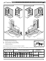
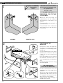
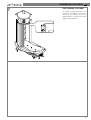
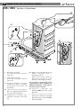
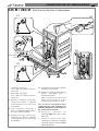
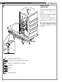
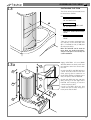
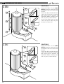
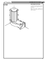
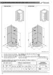
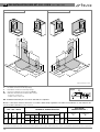
GB PRE-INSTALLATION CARD ART. 226 - 226 M
Model standard
(mm 1700 x 705)
Model turned 180°
67
0
0
80
80
11
00
00
1500
52
2130
0
11
15
1500
2220
2130
52
2220
67
0
0
15
0
50
*
17
00
565
0
55
5
70
0
85
*
0
00
350
350
00
565
50
10
1
55
0
70
85
00
17
5
0
Measurements in mm.
-
Hot water connection for 1/2" tap fittings
Cold water connection for 1/2" tap fittings
Connection for drainage pipe recessed in floor Ø40 mm
IPX5 box with PG13.5 and PG9 cable clamps
- ELECTRICAL CONNECTION
- ALARM SYSTEM CONNECTION
Siphon
97
C
F
O
CA
Ø 40
* Overall dimensions of model with panel
160
N.B. Installation must take place once floors and walls are completed.
Electric connections must be effected in accordance with safety regulations for bathroom installation as described in the
INSTALLATION STANDARDS manual attached.
ART. 226 - 226 M
Whirlpool
Multifunctions
Water
Net
Floor Delivery Delivery
Weight Content(1) Load
Weight Volume Vers.
Water
Vert. Foot Cent. Capacity
Air
Kg. Kg/m2
Kg.
Kg.
m3 No. Jets Capacity Capacity Jets Jets Sh.He.
l/min
210
300
Easy 6 l/min.
l/min.
102 190
300
198 2,79
6 2
9 ÷16
1
280
400
Top 8 l/min.
l/min.
(1) - Overflow level.
ELECTRICAL
CHARACTERISTICS
HYDRAULIC CHARACTERISTICS
Min.Max.
Pressure
2÷5
bar
Whirlpool
Art.
Installed power
Kw
1WEX38
1
2WTX38
1,35
Drain
Supply Conn.
1/2"
Ø 40
mm
(2)
(2) - Before connecting the appliance, make sure that the voltage indicated on the rating plate is the same as that of the electric mains.
The information and characteristics shown do not bind Teuco Guzzini Spa who reserves the right to make any modifications it retains necessary without any prior warning or notice of replacement.
16
PRE-INSTALLATION CARD ART. 284 - 284 M
Model standard
Model turned 180°
67
0
0
80
10
00
1500
00
10
15
0
15
0
16
55
0
70
5
85
0
0
55
5
70
0
85
00
0
50
350
350
0
565
50
50
565
*
52
80
2135
0
1500
2220
2135
52
2220
67
0
50
GB
(mm 1600 x 705)
*
00
16
Measurements in mm.
-
Hot water connection for 1/2" tap fittings
Cold water connection for 1/2" tap fittings
Connection for drainage pipe recessed in floor Ø40 mm
IPX5 box with PG13.5 and PG9 cable clamps
- ELECTRICAL CONNECTION
- ALARM SYSTEM CONNECTION
Siphon
97
C
F
O
CA
Ø 40
* Overall dimensions of model with panel
160
N.B. Installation must take place once floors and walls are completed.
Electric connections must be effected in accordance with safety regulations for bathroom installation as described in the
INSTALLATION STANDARDS manual attached.
ART. 284 - 284 M
Whirlpool
Multifunctions
Water
Net
Floor Delivery Delivery
Weight Content(1) Load
Weight Volume Vers.
Water
Vert. Foot Cent. Capacity
Air
Kg. Kg/m2
Kg.
Kg.
m3 No. Jets Capacity Capacity Jets Jets Sh.He.
l/min
Easy 6
105
180
324
200
2,76
Top 6
(1) - Overflow level.
ELECTRICAL
CHARACTERISTICS
HYDRAULIC CHARACTERISTICS
300
210
l/min.
l/min.
6
2
1
9 ÷16
Min.Max.
Pressure
2÷5
bar
Drain
Supply Conn.
1/2"
Ø 40
mm
Whirlpool
Art.
1WEX38
(2)
Installed power
Kw
1
1WTX38
(2) - Before connecting the appliance, make sure that the voltage indicated on the rating plate is the same as that of the electric mains.
The information and characteristics shown do not bind Teuco Guzzini Spa who reserves the right to make any modifications it retains necessary without any prior warning or notice of replacement.
17
GB ASSEMBLING THE CABIN
1
Always use NEUTRAL,
NON-ACETIC
silicone.
All screws and accessories which
are necessary for installation are in
the appropriate box
Bag (A) - screws
for steps 1 - 3 - 4 - 5
0
53
0
59
0
P
0
PREPARING FOR FIXTURE
TO THE WALL
P
Make the holes for fixing the
hydroshower to the wall using the
measurements indicated in the
diagram.
53
P
2090
2090
P
59
Fix bracket (P) to the wall with a
screw and fischer.
For the model with a towel-rack
wall, fasten only the bracket (P) as
indicated (!).
NORMAL
ROTATED 180°
POSITIONING THE
BATHTUB
2
X3
X2
X1
Remove the screws indicated with
the arrows to remove the front and
side panels, in the following order:
X1, X2, X3.
Pull the bottom part of the panel
towards you so that the clips (Y)
come out of their respective
housings.
Place the bathtub in the corner of
the bathroom and make sure it is
level by regulating the adjustable
feet.
Prepare the drain connection using
the trap supplied.
ONLY FOR VERSION
WITH THE TOP WHIRLPOOL
Y
18
Fit the control panel into the
appropriate hole on the edge of the
bathtub.
Since the panel may be turned
approximately 90°, make sure that
it is rotated in the correct direction
when fitting it to the bathtub.
Tighten the nut firmly and apply a
thread-locking liquid.
ASSEMBLING THE CABIN GB
3
Bag (C) - plastic accessories
ASSEMBLING THE BACK
PANEL
C
Move the bathtub away from the
corner in order to proceed with
subsequent assembly steps.
Take the back panel (A) and
remove the towel-rack panel (B) by
sliding it upwards so that it
unhooks from the fastening plates
on the frame of the back panel.
Before positioning and bolting the
column (A), apply silicone sealant
around the fixing hole in the rim of
the tub.
Position the back panel (A) on the
bathtub and fasten it using the
screw, nuts and washer.
Fit the rubber doorstop onto the
back panel (A) with the screw and
washer (C1).
B
A
M3x8
Ø4x16
M5x25
Ø6-M5
C1
M
4
INSTALLING THE SIDE
PANEL
A
A1
C1
A
Ø6-M5
A1
4,2x45
Ø6
C2
C
C
C
Move the back panel (A) away from
the bottom track.
Remove the screw (C2) from the
end of the bottom track.
Apply silicone to the groove in the
track and at the point indicated on
the bathtub.
Slide the panel (A1) into the track.
Place the threaded pins onto the
support for the side panel (A1) so
that they match up with the holes
on the back panel (A); if necessary,
use a 2.5 Allen wrench.
Check that the seal (!) fits properly
along the entire length of the side
panel support.
Fasten the back panel (A) to the
bathtub with the appropriate
screws (C) and to the bottom track
with the screw and washer removed
previously (C2).
19
GB ASSEMBLING THE CABIN
5
INSTALLING THE TOP TRACK
Remove the screws from the ends
of the top track.
Insert the track onto the ends of
the supports and onto the side
panel (A1).
Fasten the top track to the back
panel using the screws and washers
(C1) that were removed.
Tighten the screws on the ends of
the side panel support (A1).
C1
4,2x45
Ø6
C1
A1
APPLYING SILICONE
6
A
A
20
Apply a NEUTRAL (NON ACETIC)
silicone to prevent water from
leaking between the back panel
and the bathtub.
If the cabin comes equipped with a
towel-rack panel, mount it by
hooking it onto the appropriate
fastening plates on the back panel
(A).
Make sure that the edge of the
towel-rack panel fits into the slot in
the trim on the back panel, as
illustrated.
ASSEMBLING THE CABIN GB
7
POSITIONING THE DOME
In order to proceed with the
electrical and water connections,
position the dome onto the
hydroshower, inserting the front
edge into the top track.
21
GB CONNECTIONS FOR THE VARIOUS MODELS
226 / 284 - Synthesis Hydroshower
A3
5
A1
F
9
9
C
5
A4
CA
Blue N
Yellow and Green
Brown P
T
F
4
C
9
A2
5
4
4
C - Hot water connection
Use a 60 cm flexible stainless
steel hose.
F - Cold water connection
Use a 60 cm flexible stainless
steel hose .
A1 - Shower assembly connection
using hose 9 which is supplied
and fastened to the cabin and
the diverter.
A2 - Tap connection using tube 4
which is supplied and fastened to
the cabin and the diverter.
A3 - Showerhead assembly with
nebulizer and water connection
(5).
22
A4 - Water connection diagram for the
model equipped with a
thermostatic mixer.
When installing the stopcock;
make sure to install it in the
direction indicated by the arrow.
The electrical installation must
comply with the safety regulations for
bathroom installation, as described in
the enclosed user’s manual.
CA - Electrical connection for
whirlpool IPX5 (box with clamp
PG 13.5)
T - Electrical connection for alarm
system (only if bathroom is equipped
with alarm system) (version HYDRO
TOP uniquement).
CONNECTIONS FOR THE VARIOUS MODELS GB
226 M / 284 M - Multifunction Synthesis Hydroshower
A1
A4
5
9
A2
9
F
5
C
4
Blue N
Yellow and Green
Brown P
A5
CA
T
F
C
9
4
11
A3
5
4
11
11
C - Hot water connection
Use a 60 cm flexible stainless
steel hose.
F - Cold water connection
Use a 60 cm flexible stainless
steel hose .
A1 - Shower assembly connection
using hose 9 which is supplied
and fastened to the cabin and
the diverter.
A2 - Tap connection using tube 4
which is supplied and fastened to
the cabin and the diverter.
A3 - Shower massage connection
using tube 11 which is supplied
and fastened to the cabin and
the diverter.
A4 - Showerhead assembly with nebulizer
and water connection (5).
A5 - Water connection diagram for the
model equipped with a
thermostatic mixer.
When installing the stopcock;
make sure to install it in the
direction indicated by the arrow.
The electrical installation must
comply with the safety regulations for
bathroom installation, as described in
the enclosed user’s manual.
CA - Electrical connection for
whirlpool IPX5 (box with clamp
PG 13.5)
T - Electrical connection for alarm
system (only if bathroom is equipped
with alarm system) (version HYDRO
TOP uniquement).
23
GB CONNECTIONS FOR THE VARIOUS MODELS
9
EQUIPOTENTIAL
CONNECTION
2
1
3
4
7
24
5
6
1
SHOWER SUPPORT POLE
2
STOPCOCK FOR THERMOSTATIC MIXER
3
MIXER OR THERMOSTATIC MIXER
4
DIVERTER
5
FRAME
6
TAP
7
PUMP SUPPORT
Use the yellow-green wire to
connect the metal parts of the
appliance, as shown in the
diagram.
Connect the other yellow-green
wire, which is under the bathtub
edge, where indicated.
A clamp for the equipotential
connection to other earth wires in
the bathroom is available at point
(7).
N.B.: Should your model not have
one of the components shown in
the diagram, insulate the relative
"fast-on".
ASSEMBLING THE CABIN GB
10
FITTING THE DOOR
P
C
R
R
D
V
Y
T
P
V
Insert the track covers (V) and the
end-trim (Y) into the top track.
Turn the nut (D) until it is flush with
the top of the “C” screw.
Fit the door from inside the cabin
by inserting the bottom edge of the
door into the slide assembly (S)
located on the bathtub. Hook the
bearing (P) onto the top track.
In order to hook bearing (R) onto
the top track, close the door and
insert it at the point shown in the
diagram. Fasten the trim piece (T)
onto the track.
Hook the door so that the lower
wheel slide into the track.
Y
S
11
11 Bag (C) - screws
for steps 11 - 13
K
D
CENTRING THE DOOR
Fit the handle onto the door
support and fix it with some
thread-locking liquid. Then insert
the piece of trim.
M4x30
A
B
Close the door and make sure that
the magnetic seals adhere along
the entire length of the supports.
In the event that the seals do not
come together - as in case (A) or
case (B) - adjust the top slide
assembly indicated by the arrow.
- Lift the door, grasping it by the
supports.
- Tighten the screw (D) until the
magnetic seals are aligned.
N.B. After adjusting the slide
assembly, lock the nuts (D) in place,
inserting the covers (K) with the
inner wings facing outwards.
25
GB ASSEMBLING THE CABIN
12
C
M5x16
Ø6
C
C
C1
M5x16
Ø6
C2
C1
C1
T1
Y
T
FIXTURE TO WALL
Move the hydroshower into the
corner of the bathroom.
Fix the bathtub to the floor with
plates (T) using screws and
fischers.
Lift the dome and fasten the cabin
to the wall using plate (T1) and the
screws with washers (C1).
Fasten the dome to the
hydroshower with the screws and
washers (C).
For the cabin with the towel-rack
panel, fasten the bracket (T2) to
the wall using a screw and fischer
and to the dome with a screw and
washer(C2).
26
Re-install the bathtub panel in the
reverse order by inserting the top
edge underneath the bathtub and
pressing the clips (Y) so that they
go back into their respective
housings; fasten the panels with
the screws which were removed
previously.
Position the seat on the inside
edge of the bathtub and slide it
into its housing with a turning
motion all the way beneath the
back panel.
4,2x12,7
Ø5
T2
ASSEMBLING THE CABIN GB
13
INSTALLING THE TRIM
The finish trim (if purchased) must
be installed as follows:
B1
TRIM FOR THE LONG SIDE
OF THE BATHTUB
P
L
B2
TRIM FOR THE SHORT SIDE
OF THE BATHTUB
B3
VERTICAL TRIM FOR OUTSIDE
EDGE
B4
VERTICAL TRIM FOR INSIDE
EDGE
Take the necessary measurements
(L) and (P); cut the trim (B1) and
(B2 - if needed) to size, (L-30) and
(P-63) respectively.
N.B.: The trim kit can be used for
more than one model; therefore,
only use the pieces necessary for
each installation.
13a
Apply NEUTRAL silicone (NON
ACETIC) where the back panel and
the bathtub come into contact with
the wall.
Install trim (B1) and (B4) with the
corner trim (A) and the end trim
(A3), paying special attention to
make them adhere uniformly to the
wall, the panel, and the bathtub.
Install trim (B2) with the end trim
(A2), placing it on the edge of the
bathtub and inserting it onto the
corner trim piece (A1).
Install trim (B3) with the two
corner trim pieces (A2) along the
back panel and the wall.
A3
A3
B4
B3
A
B1
A1
A3
B2
A2
27
GB ASSEMBLING THE CABIN
13b
SOLUTION 2
Apply NEUTRAL silicone (NON
ACETIC) where the back panel and
the bathtub come into contact with
the wall.
Install trim (B1) and (B4) with the
corner trim (A) and the end trim
(A3), paying special attention to
make them adhere uniformly to the
wall, the panel, and the bathtub.
Install trim (B3) with the two
corner trim pieces (A2) along the
back panel and the wall.
A3
A3
B4
B3
A
B1
A2
A3
13c
SOLUTION 3
Apply NEUTRAL silicone (NON
ACETIC) where the back panel and
the bathtub come into contact with
the wall.
Install trim (B1) and (B4) with the
corner trim (A) and the end trim
(A3), paying special attention to
make them adhere uniformly to the
wall, the panel, and the bathtub.
A3
B4
A
B1
A2
28
ASSEMBLING THE CABIN GB
13d
FASTENING THE TRIM
Use adhesive tape to keep the trim
in place on the bathtub and the
back panel.
After four hours, remove the
adhesive tape and clean off any
excess silicone.
29