1
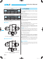
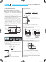
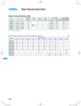
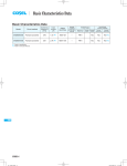
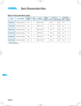
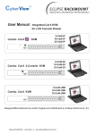
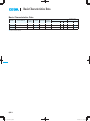
Basic Characteristics Data
Basic Characteristics Data
Model
Circuit method
CQHS250 Full-bridge converter
Switching
frequency
[kHz]
Input
current
Rated
input fuse
Inrush
current
protection
Material
140
*1
-
-
glass fabric base, epoxy resin
Series/Redundancy
operation availability
PCB/Pattern
Single
sided
Double
sided
Series
operation
Redundancy
operation
Multilayer
Yes
*2
CQHS300
Forward converter
250
*1
-
-
Aluminum
Yes
Yes
*2
CQHS350
Forward converter
250
*1
-
-
Aluminum
Yes
Yes
*2
*1 Refer to Specification.
*2 Refer to Instruction Manual.
CQHS
CQHS-8
DC-DC Converters Bus Converter.Power Module Type
Instruction Manual
1
Pin Configuration
CQHS-10
2
Connection for Standard Use
CQHS-10
3
Wiring Input/Output Pin
CQHS-11
4
5
6
7
3.1
Wiring input pin
CQHS-11
3.2
Wiring output pin
CQHS-11
Function
CQHS-12
4.1
Overcurrent protection and Low voltage protection
CQHS-12
4.2
Overvoltage protection
CQHS-12
4.3
Thermal protection
CQHS-12
4.4
Remote ON/OFF
CQHS-13
4.5
Remote sensing
CQHS-13
4.6
Adjustable voltage range
CQHS-14
4.7
Withstanding Voltage / Isolation Voltage
CQHS-14
Series and Parallel Operation
CQHS-15
5.1
Series operation
CQHS-15
5.2
Redundancy operation
CQHS-15
Implementation-Mounting Method
CQHS-15
6.1
Mounting method
CQHS-15
6.2
Stress onto the pins
CQHS-16
6.3
Cleaning
CQHS-16
6.4
Soldering temperature
CQHS-16
6.5
Derating
CQHS-16
6.6
Heat sink (CQHS300/CQHS350 Optional parts)
CQHS-17
Safety Considerations
CQHS-18
CQHS-9
CQHS
DC-DC Converters Bus Converter . Power Module Type
1 Pin Configuration
2 Connection for
Standard Use
¿ CQHS250
8
7
6
5
4
-VIN 3
RC 2
+VIN 1
Instruction Manual
-VOUT
-S
TRM
+S
+VOUT
¡The power module needs input and output connection as shown
in Fig.2.1 or Fig.2.2.
Reference: 3
”Wiring Input/Output Pin”
6.5
”Derating”
¡Short the following pins to turn on the power supply.
-VIN RC, +VOUT +S, -VOUT -S
Reference: 4.4
¿ CQHS300/CQHS350
”Remote ON/OFF”
4.5
”Remote sensing”
2-Mounting hole
¡Only DC voltage can be applied to CQHS Series. Applying AC
voltage will damage the power module.
¿ CQHS250
8
7
6
5
4
-VIN 3
RC 2
+VIN 1
-VOUT
-S
TRM
+S
+VOUT
F1
DC
input
+VIN
Cin
Cout
+
RC
-VIN
Table 1.1 Pin Assignment
No.
1
2
3
4
5
6
7
8
-
Pin Name
+VIN
RC
-VIN
+VOUT
+S
TRM
-S
-VOUT
Mounting hole
Function
+DC input
Remote ON/OFF
-DC input
+DC output
+Remote sensing
Adjustment of output voltage
-Remote sensing
-DC output
Mounting hole
No.
1
2
3
4
5
6
7
8
-
Pin Name
+VIN
RC
-VIN
+VOUT
+S
TRM
-S
-VOUT
Mounting hole
Reference
3.1 ”Wiring input pin ”
4.4 ”Remote ON/OFF ”
3.1 ”Wiring input pin ”
3.2 ”Wiring output pin ”
4.5 ”Remote sensing ”
4.6 ”Adjustable voltage range ”
4.5 ”Remote sensing ”
3.2 ”Wiring output pin ”
6.1 ”Mounting method ”
CQHS-10
+
Load
-VOUT
-S
Fig.2.1 Connection for Standard Use (CQHS250)
Fig.1.1 Pin configuration (bottom view)
CQHS
+S
+VOUT
¿ CQHS300/CQHS350
Heat sink
F1
DC
input
CY
Cin
+
Mounting hole
+VIN
+S
+VOUT
Cout
RC
-VIN
+
Load
-VOUT
-S
Fig.2.2 Connection for Standard Use (CQHS300/CQHS350)
Table 2.1 External components
No. Symbol
Component
1
F1
Input fuse
Primary decoupling
2
CY
capacitor
External capacitor
3
Cin
on the input side
External capacitor
4
Cout
on the output side
Heat sink
5
Reference
3.1(1) ”External fuse”
3.1(2) ”Noise Filter/Decoupling
Capacitor”
3.1(3) ”External capacitor on the
Input”
3.2 ”Wiring output pin”
6.5 ”Derating”
DC-DC Converters Bus Converter . Power Module Type
3 Wiring Input/Output Pin
3.1 Wiring input pin
Instruction Manual
(4) Input Voltage Range/Input Current Range
¡Keep the input voltage ripple within the specification below. Output ripple voltage will increase as these values increase.
Ripple voltage CQHS250/300/350 : less than 4Vp-p
¡Make sure that the peak input voltage stays within the specified
input voltage range of the power module.
(1) External fuse
¡The input circuit of CQHS Series does not come with a built-in
fuse. In order to protect the power module, a normal-blow fuse
¡Choose a front end power supply that can supply enough current
Ip (Fig. 3.2) for starting up the power module.
Table 3.1 Recommended fuses (Normal-blow type)
Model
CQHS25048
CQHS30048
CQHS35048
Rated current
15A
20A
20A
Ripple
voltage
Time
Input voltage range
ule.
Input voltage [V]
should be installed to +VIN.
¡When multiple modules get input voltage from a single front-end
power supply, a normal-blow fuse must be installed to each mod-
t
Fig.3.1 Input Voltage Ripple
(2) Noise Filter/Decoupling Capacitor
Input voltage range
Input current [A]
¡An appropriate filter must be used if conformance to the conducted noise regulation is required or if surge voltage may be applied
to the unit. Please consult us for more details.
¿ CQHS300/CQHS350
¡A decoupling capacitor CY must be used to reduce the line noise
on the input line and stabilize the power module operation (Fig.
Input voltage [V]
Fig.3.2 Input Current Characteristics
2.2). Note that resonance and inductance from the input line filter
may cause the power module to become unstable.
¡Install a decoupling capacitor CY of at least 4700 pF as close to
the input pins as possible (within 50mm of the pins).
¡If the total capacitance of the decoupling capacitor exceeds 15000
pF, the specified isolation voltage between input and output may
not be satisfied. In this case, either reduce the capacitance of the
lp
¡Avoid applying reversed-polarity voltage to the power module as it
will damage the power module. To protect the power module from
reversed polarity voltage, installing an external diode as shown in
Fig. 3.3 is recommended.
+VIN
DC IN
-VIN
decoupling capacitor at the input or install a decoupling capacitor
to the output.
(3) External capacitor on the Input
¡An external capacitor Cin must be installed between +VIN and
-VIN to reduce line noise and stabilize the power module operation (Fig. 2.1 and Fig.2.2).
Capacitance CQHS250/300/350 : at least 68 FX2
CQHS250
Ta=-20 to +85C Electrolytic or Ceramic capacitor
Ta=-40 to +85C Ceramic capacitor
CQHS300/CQHS350
Tc=-20 to +100C Electrolytic or Ceramic capacitor
Tc=-40 to +100C Ceramic capacitor
¡The capacitor must be installed less than 50mm of the power
module. As ripple current will flow through this capacitor, pay attention to the ripple current rating of the capacitor.
CQHS
(5) Reverse Input Voltage Protection
Fig.3.3 Reverse Input Voltage Protection
3.2 Wiring output pin
¡Install an external capacitor Cout between +VOUT and -VOUT to
increase stability of output (Fig. 2.1 and Fig.2.2).
Recommended capacitance of Cout is shown in Table 3.2 and
Table 3.3.
¡Choose a high frequency type electrolytic capacitor for Cout. Output ripple and rise time will be influenced by the capacitor’s ESR
and ESL and the wiring impedance.
¡As ripple current will flow through capacitor Cout, pay attention to
the ripple current rating of the capacitor.
¡Install capacitor Cout as close to the power module as possible
(within 50mm).
¡If the power module is to be turned ON/OFF directly with a switch,
inductance from the input line will induce a surge voltage several
This is useful for reducing radiated noise and increasing stability
times that of the input voltage and it may damage the power mod-
¡When the capacitance of external output capacitor Cout is high, it
may unstabilize the operation of power supply, so please refer to
ule. Make sure that the surge is absorbed, for example, by connecting an electrolytic capacitor between the input pins.
of the power module operation.
Table 3.2 and Table 3.3 for the value of the external capacitor Cout.
CQHS-11
DC-DC Converters Bus Converter . Power Module Type
Table 3.2 Capacitance Values for External Output Capacitor Cout [ F]
(CQHS250)
Recommended capacitance
Ambient temperature
Ta=-40~-20C
Ta=-20~0C
Ta=0~+85C
470
470
220
330
100
100
Output
voltage(V)
32
50
2200
1000
Recommended capacitance
Maximum
Base plate temperature
capacitance
Tc=-40~-20C
Tc=-20~0C
Tc=0~+100C
470X2
470X2
470
3300
330X2
330
330
2200
32
50
¡The specified ripple and ripple noise are measured by the method
introduced in Fig. 3.4 and Fig.3.5.
Measuring board
+S
+VIN 㧗VOUT
Overcurrent protection prevents the unit from short circuit and
overcurrent condition.
¡The DC output will be shut down, when the output voltage drops
under the output voltage adjustment range (low voltage protection).
¡Recovery from the protection is accomplished by applying 5VDC
or less input for at least 1 second, or toggling remote ON / OFF
signal for at least 1 second.
¡Recovery from the protection is accomplished by applying 5VDC
or less input for at least 1 second, or toggling remote ON / OFF
signal for at least 1 second.
+
+
RC
0.1mF
Cout
Load
Remarks :
Please note that devices inside the power supply might fail when
-VIN -VOUT
CQHS
¡Overcurrent protection is built-in and comes into effect at over
105% of the rated current.
¡The overvoltage protection circuit is built-in. The DC input should
be shut down if overvoltage protection is in operation.
50mm
Cin
4.1 Overcurrent protection and Low voltage
protection
4.2 Overvoltage protection
¿ CQHS250
DC
input
4 Function
Maximum
capacitance
Table 3.3 Capacitance Values for External Output Capacitor Cout [ F]
(CQHS300/CQHS350)
Output
voltage(V)
Instruction Manual
voltage more than rated output voltage is applied to output pin of
the power supply. This could happen when the customer tests the
-S
overvoltage performance of the unit.
Oscilloscope
BW㧦100MHz
1. 5m 50W
Coaxial Cable
R
C
4.3 Thermal protection
R=50W
C=0.01mF
¡Over Temperature Protection (OTP) is built in. If the temperature
of PCB exceed 120C (CQHS250) or the base plate temperature
Fig.3.4 Method of Measuring Output Ripple and Ripple Noise
(CQHS250)
exceed 100C (CQHS300/CQHS350). OTP will work, causing the
output voltage to drop.
¡Recovery from the protection is accomplished by applying 5VDC
or less input for at least 1 second, or toggling remote ON / OFF
¿ CQHS300/CQHS350
signal for at least 1 second, after the unit should be cool down.
50mm
CY
Measuring board
Mounting +S
4700pF hole
+VIN 㧗VOUT
Cout Co
DC
input
+
+
Cin
¡Option ”-N” means the output voltage of the power module will be
recovered automatically when the fault condition (such as OCP,
+
RC
0.1mF
Load
-VIN -VOUT
-S
Oscilloscope
BW㧦100MHz
R
C
1. 5m 50W
Coaxial Cable
R=50W
C=0.01mF
Co32V㧦470mF
50V㧦220mF
Fig.3.5 Method of Measuring Output Ripple and Ripple Noise
(CQHS300/CQHS350)
CQHS-12
¿ -N (CQHS250)
OVP or OTP) is corrected.
DC-DC Converters Bus Converter . Power Module Type
Instruction Manual
4.4 Remote ON/OFF
4.5 Remote sensing
¡The remote ON/OFF function is incorporated in the input circuit
and operated with RC and -VIN. If positive logic control is re-
(1) When Remote Sensing is Not Used
quired, order the power module with “-R” option.
+S
Table 4.1 Remote ON/OFF Specifications (CQHS250)
ON/OFF logic
Between RC and -VIN
L level(0 - 1.0V) or short
Standard Negative
H level(4.0 - 7.0V) or open
L level(0 - 1.0V) or short
Optional
Positive
-R
H level(4.0 - 7.0V) or open
Output voltage
ON
OFF
OFF
ON
¡When RC is at low level, a current of 0.1mA typ will flow out.
When Vcc is used, keep it within the following rage:
4 [ VCC [ 7V.
When remote ON/OFF is not used, short RC and -VIN.
+VOUT
+
Load
Cout
-VOUT
-S
Short at pin root
Fig. 4.2 When Remote Sensing is Not Used
¡When remote sensing is not used, make sure +VOUT and +S are
shorted, and that -VOUT and -S are shorted as well.
¡Keep the patterns between +S and +VOUT and between -S and
-VOUT as short as possible. Avoid a looping pattern. If noise enters the loop, the operation of the power module will become unstable.
Table 4.2 Remote ON/OFF Specifications (CQHS300/CQHS350)
ON/OFF logic
Between RC and -VIN
L level(0 - 1.2V) or short
Standard Negative
H level(3.5 - 7.0V) or open
L level(0 - 1.2V) or short
Optional
Positive
-R
H level(3.5 - 7.0V) or open
(2) When Remote Sensing is Used
Output voltage
ON
OFF
OFF
ON
Wire as close as possible
+S
+VOUT
¡When RC is at low level, a current of 0.5mA typ will flow out.
When Vcc is used, keep it within the following rage:
-VOUT
-S
3.5 [ VCC [ 7V.
+
Cout
Load
Fig. 4.3 When Remote Sensing is Used
When remote ON/OFF is not used, short RC and -VIN.
Vcc
RC
RC
-VIN
Opto coupler
-VIN
Transistor
RC
RC
-VIN
IC
-VIN
¡Using remote sensing with long wires may cause output voltage to
become unstable. Consult us if long sensing wiring is necessary.
¡Sensing patterns or wires should be as short as possible. If wires
are used, use either twisted-pair or shielded wires.
¡Use wide PCB patterns or thick wires between the power module
and the load. Line drop should be kept less than 0.3V. Make sure
output voltage from the power module stays within the specified
range.
Relay
Fig. 4.1 RC Connection Example
¡If the sensing patterns are shorted by mistake, a large current may
flow and damage the pattern. This can be prevented by installing
fuses or resistors close to the load.
As wiring or load impedance may generate oscillation or large
fluctuations in output voltage, make sure enough evaluation is
given in advance.
CQHS-13
CQHS
DC-DC Converters Bus Converter . Power Module Type
(3) Output voltage increasing
4.6 Adjustable voltage range
¡By connecting the external resistor (RU), output voltage becomes
adjustable to increase.
(1) Output voltage adjusting
¡Output voltage is adjustable by the external potentiometer.
¡When the output voltage adjustment is used, note that the over
The external resistor (RU) is calculated the following equation.
voltage protection circuit operates when the output voltage sets
VORX㧔100㧑+ 㧑㧕
RU=
too high.
¡If the output voltage drops under the output voltage adjustment
range, note that the Low voltage protection operates.
recommended external parts are shown in Table 4.2.
¡The wiring to the potentiometer should be as short as possible.
The temperature coefficient becomes worse, depending on the
1
VR1
5kW
3
-S
-VOUT
Fig. 4.4 Output voltage control circuit
Table 4.2 Recommended Values of External Resistors
1
2
32V
50V
¡By connecting the external resistor(RD), output voltage becomes
adjustable to decrease.
The external resistor(RD) is calculated the following equation.
100㧑
㧑=
Δ㧑
-2 [kW]
VOR㧙VOD
VOR
90
32
85
0
0
38
36
40
42
100
50
90
32
84
0
0
INPUT VOLTAGE [V]
36
38
40
42
INPUT VOLTAGE [V]
CQHS25048
Fig. 4.7 Output voltage adjustment range
(5) Output current derating (CQHS3504832)
X100
12.0
11.5
11.0
10.5
10.0
0
0
26.88 28.0
32.0
35.2
Output voltage [V]
Fig. 4.8 Output Current derating curve (CQHS3504832)
CQHS +VOUT
+S
VOR :Rated output voltage[V]
VOD :Output voltage needed to set up[V]
TRM
RD
-S
-VOUT
Fig. 4.5 Connection for output voltage decreasing
CQHS-14
50
32, 50
110
¡When the output voltage adjust less than rated output voltage, the
output current range becomes increasing as shown in Fig. 4.8.
(2) Output voltage decreasing
RD=
100
Output current [A]
VOUT
Adjustable range
VOUT±5%
VOUT±10%
R1
R2
R1
R2
51kW
51kW
11kW
6.2kW
82kW
82kW
32, 50
110
ADJUSTMENT RANGE [%]
¡When the input voltage is 36 - 40VDC , the output voltage adjustment range becomes as shown in Fig. 4.7.
ADJUSTMENT RANGE [%]
+S
TRM R2 2
No.
Fig. 4.6 Connection for output voltage increasing
(4) Intput voltage derating
2.5V
RC
1kW
VOR :Rated output voltage[V]
VOU :Output voltage needed to set up[V]
+VOUT
R1
RB
2kW
X100
-S
-VOUT
¡When the output voltage adjustment is not used, open the TRM
pin respectively.
CQHS
ާkWި
TRM
Potentiometer....Cermet type, coefficient of less than ±300ppm/C
㧗
VOR
㧑
RU
mended for the power supply.
Resistor.............Metal film type, coefficient of less than ±100ppm/C
RA
2kW
VOU-VOR
CQHS +VOUT
+S
type of a resistor and potentiometer. Following parts are recom-
Control Amp.
of rated
㧙
voltage
㧔100㧑+2X 㧑㧕
1.225X 㧑
㧑=
¡By connecting the external potentiometer (VR1)and resistors
(R1,R2),output voltage becomes adjustable, as shown in Fig.4.4,
CQHS
Instruction Manual
4.7 Withstanding Voltage / Isolation Voltage
¡When testing the withstanding voltage, make sure the voltage is
increased gradually. When turning off, reduce the voltage gradually by using the dial of the hi-pot tester. Do not use a voltage tester
with a timer as it may generate voltage several times as large as
the applied voltage.
DC-DC Converters Bus Converter . Power Module Type
5 Series and Parallel
Operation
Instruction Manual
6 ImplementationMounting Method
5.1 Series operation
6.1 Mounting method
¡Series operation is available by connecting the outputs of two or
more power supplies, as shown below. Output current in series
¡When multiple power modules are used side by side, position
them with sufficient spaces to allow adequate air ventilation so
connection should be lower than the lowest rated current in each
that the temperature of each power module will remain within the
unit.
temperature range shown in the derating curves.
(a)
¡Do not pass the DC input pattern underneath the power module
as this will increase conducted noise. Place the DC input pattern
Power +
Supply Load
away from the power module.
Do not pass the DC output pattern underneath the power module
as this will increase output noise. Place the DC output pattern
Power +
Supply Power +
Supply -
on the PCB to let it act as a shield and connect this pattern to the
Load
(b)
away from the power module.
¡High frequency noise is radiated from the power module. When
mounting the power module on a PCB, leave a copper pattern
mounting hole.
Power +
Supply -
Load
¿ CQHS250
¡Avoid placing pattern layout in hatched area shown in Fig.6.1 to
insulate between pattern and power supply.
48.5
Fig. 5.1 Examples of series operation
5.2 Redundancy operation
+VIN
¡Parallel operation is not possible.
¡Redundancy operation is available by wiring as shown below.
+VOUT
+S
TRM
-S
-VOUT
RC
-VIN
+S
+VOUT
I1
I3
Fig.6.1 Prohibition area of pattern layout (top view)
Load
-VOUT
-S
+S
+VOUT
CQHS
5.0
I2
-VOUT
-S
Fig. 5.2 Example of Redundancy Operation
¿ CQHS300/CQHS350
¡Soldering CQHS series with printed board must be done under
the flat condition by using the mounting hole and fixing with the
screw.
If CQHS series is inclined and it’s mounted, the insulation of the
internal components and printed board might not be kept.
¡Even a slight difference in output voltage can affect the balance
between the values of I1 and I2.
Please make sure that the value of I3 does not exceed the rated
current of a power supply.
I3
the rated current value
¡When a heat sink cannot be fixed on the base plate side, order the
power module with ”-T” option. A heat sink can be mounted by affixing a M3 tap on the heat sink.
Please make sure a mounting hole will be connected to a grounding
capacitor CY.
Table 6.1 Mounting Hole Configuration
Standard
Optional : -T
Mounting hole
M3 tapped
f3.4 thru
CQHS-15
DC-DC Converters Bus Converter . Power Module Type
Instruction Manual
6.2 Stress onto the pins
6.5 Derating
¡Applying excessive stress to the input or output pins of the power
module may damage internal connections. Avoid applying stress
¡It is necessary to note the thermal fatigue life by power cycle.
Please reduce the temperature fl uctuation range as much as
in excess of that shown in Fig. 6.2 and Fig.6.3.
possible when the up and down of the temperature are frequently
¡Input and output pins are soldered onto the internal PCB. Do not
bend or pull the leads with excessive force.
generated.
Contact us for more information on cooling methods.
¿ CQHS300/CQHS350
¿ CQHS250
¡As unexpected stress may be applied to the pins, set the diameter
of the PCB mounting hole at 3.5mm.
¡Use with the convection cooling or the forced air cooling.
Make sure the temperatures at temperature measurement loca-
¡As unexpected stress may be applied to the pins from vibration
or shock, fix the power module by using the mounting holes with
tions shown from Fig.6.4 below are on or under the derating curve
Ambient temperature must be kept at 85C or under.
¡Fix the power module to the PCB with the screws before soldering
the input and output pins to prevent the PCB pattern being damaged.
-VOUT
-S
TRM
+S
+VOUT
-VIN
RC
+VIN
+VOUT, -VOUT
Less than
19.6N(2kgf)
100
80
60
40
20
0
-40
-20
Less than
19.6N
Less than
19.6N(2kgf)
Less than
39.2N
40
60
80
100
Temperature of measurement location
+VIN
+VOUT, -VOUT
Others
Less than
9.8N(1kgf)
Less than
39.2N(4kgf)
¡For option “B” which is used with the convection cooling, forced air
cooling or conduction cooling, use the temperature measurement
location as shown in Fig.6.5.
1Vin=DC36-60V
CQHS2504850
100
Load factor[%]
RC
Less than
9.8N(1kgf)
Less than
19.6N(2kgf)
¡Clean the soldered side of the power module with a brush.
Prevent liquid from getting into the power module. Do not clean by
soaking the power module into liquid.
¡Do not allow solvent to come in contact with product labels in cases as this may cause deletion of the letters printed on the product
CQHS2504832
60
40
Vin : 36 - 60V
20
-20
0
20
40
60 (75)80(85) 100
Aluminum base plate temperature Tc [ C ]
2Vin=DC60-76V
100
Load factor[%]
6.3 Cleaning
80
0
-40
Fig. 6.3 Stress onto Pins (CQHS300/CQHS350)
80
60
Vin : 60 - 76V
40
(25)
20
0
-40
-20
20
40
60(65) 80 (95)100
0
Aluminum base plate temperature Tc [ C ]
labels.
¡After cleaning, dry the power modules well.
6.4 Soldering temperature
¡Flow soldering : 260C for up to 15 seconds.
¡Soldering iron (26W) : 450C for up to 5 seconds.
CQHS-16
120
Fig. 6.4 Derating curve (CQHS250)
-VOUT
-S
TRM
+S
+VOUT
-VIN
Less than
19.6N(2kgf)
20
Less than
19.6N
Fig. 6.2 Stress onto Pins (CQHS250)
Less than
19.6N(2kgf)
0
Temperature of measurement location[C]
Others
Less than
39.2N(4kgf)
CQHS
in Fig.6.4.
Load factor[%]
screws to reduce stress.
Aluminum base plate
Tc : Measuring point
Fig. 6.5 Derating curve (CQHS250 option "B")
DC-DC Converters Bus Converter . Power Module Type
¿ CQHS300/CQHS350
¡Use the power modules with conduction cooling (e.g. heat dissipation from the aluminum base plate to the attached heat sink).
Instruction Manual
6.6 Heat sink
(CQHS300/CQHS350 Optional parts)
Fig. 6.6 shows the derating curves with respect to the aluminum
¡CQHS300/CQHS350 works with conduction cooling and needs
heat dissipation using heat sinks. Optional heat sinks are avail-
base plate temperature. Note that operation within the hatched ar-
able for CQHS Series. Refer to Table 6.2 for details on the thermal
eas will cause a significant level of ripple and ripple noise. Contact
resistance of heat sinks.
us for more information on cooling methods.
¡Please measure the temperature on the aluminum base plate
edge side when you cannot measure the temperature of the center part of the aluminum base plate.
Table 6.2 Types of Heat Sinks Available
Size[mm]
No.
Model
1
2
3
4
5
6
F-QB-F1
F-QB-F2
F-QB-F3
F-QB-F4
F-QB-F5
F-QB-F6
H
W
D
12.7
12.7
25.4
25.4
38.1
38.1
58.4
58.7
58.4
58.7
58.4
58.7
37.6
37.3
37.6
37.3
37.6
37.3
In this case, please take 5deg temperature margin from the derating characteristic of Fig. 6.6.
1Vin=DC36-60V
100
Thermal resistance[C/W]
Convection
Forced Air
(0.1m/s)
14.0
7.5
5.0
Style
Horizontal
Vertical
Horizontal
Refer Fig.6.8
Vertical
Horizontal
Vertical
W
W
Vin=DC36 - 60V
Vin=36-60V
0
D
D
50
-20
0
20
40
60
80
100
H
(85)
-40
H
Load factor [%]
80
Aluminum base plate temperature Tc [C]
CQHS
Vertical
Horizontal
2CQHS300 : Vin=DC60 - 76V CQHS350 : Vin=DC60 - 65V
Fig.6.7 Heat Sink Types
100
10
CQHS300
: Vin=DC60 - 76V
Vin=60-76V
CQHS350 : Vin=DC60 - 65V
50
0
(95)
-40
-20
0
20
40
60
80
Thermal resistance(C/w)
Load factor [%]
80
8
F-QB -F1/F2
F-QB -F3/F4
F-QB -F5/F6
6
4
2
100
Aluminum base plate temperature Tc [C]
Tc : Measuring point
0
0.0
0.5
1.0
1.5
2.0
Wind velocity(m/s)
2.5
3.0
Fig.6.8 Thermal Resistance of Heat Sink(Forced Air)
Aluminum base plate
Fig. 6.6 Derating curve (CQHS300/CQHS350)
CQHS-17
DC-DC Converters Bus Converter . Power Module Type
7 Safety Considerations
¡To apply for safety standard approvals with the power module, the
following conditions must be met. Consult us for more details.
¿The power modules must be used as a component power supply
in end-use equipment.
¿Neither basic isolation nor double/reinforced isolation is provided
across input, output and the base plate of the power module. If
the power module is to be used with input voltage of more than
60VDC and needs basic or double/reinforced isolation, the required isolation must be provided in the construction of the final
product.
¿Use external fuses that comply with safety standards at the in-
put.
CQHS
CQHS-18
Instruction Manual