1
Chapter 1: General Descriptions
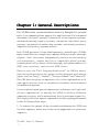
The VP-894 voice communications board is designed to provide
multi-line communications support for applications like automated
attendant/voice mail systems, interactive voice response systems,
automated banking/inquiry systems, automated order/data entry
systems, automated telemarketing systems, audiotext providers,
computerized security systems and etc.
Each VP-894 operates 4 lines simultaneously, and multiple VP-894s
may be installed into a single host computer sharing a single interrupt
request. Each line works independently and can record and play
voice messages, answer and (via a compatible phone system)
transfer phone calls, detect caller hang-ups, dial phone numbers (in
DTMF tone or pulse), and receive DTMF tones.
There is also the "Call Progress Monitoring" (or CPM for short)
function which monitors out-going calling progress with status
report such as "busy", "answer", "ring-no-answer" and "invalid".
This CPM function plays an important role in the implementation of
some applications such as automated attendant and automated
telemarketing systems.
A very sophisticated speech compression technique, with optional
silence compression, is used by the VP894 to achieve different
compression rates, while maintaining fairly good speech quality.
This highly efficient speech compression boosts system performance
in the following three ways:
1. It reduces the amount of data transferred between the VP894 and
the host computer, hence more lines can be supported in a given host
computer.
VP-894 User's Manual
1
2. It reduces the amount of data stored on the hard disk, hence more
messages can be stored on a given hard disk.
3. In a network system, it reduces the network traffic because less
amount of data needs to be transferred between nodes.
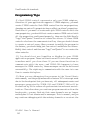
Software development for VP-894 is made quick and easy by an
efficient device driver and a powerful Application Program Interface
(API) supporting C, Clipper, Visual C (Windows) and Visual Basic
(Windows).
Under proper software control, VP-894 can do almost anything that
a human operator can do, such as answering the phone with a pleasant
greeting, taking messages, transferring calls via phone systems and
providing proper information upon request. Actually, having a VP894-based system is like having several operators working together
at the same time.
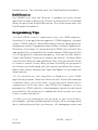
The potentials and advantages of a VP-894-based system has no
limitations. The perfect marriage of computers and telecommunications has created a market with hundreds of useful applications. It is
predicted that this trend of automated telecommunication will
completely revolutionize the way we live, think, and work.
Softw
ar
e Suppor
t
Softwa
re
Support
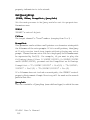
The VP-894 software support consists of a memory-resident device
driver and a library of API (Application Program Interface) functions.
The memory resident device driver must be installed before running
the application program. For the most part, the device driver is
hidden behind the API and software developers need not to learn
much about it.
Although it is possible to write your own device driver, we highly
recommend using our device driver since it makes no sense to reinvent the wheel. If you are using another operating system and
therefore have to write your own device driver, you may contact us
for more information.
2
Manual
VP-894 User's
The API library supports the following programming languages:
- (DOS) Microsoft C 7.00 and above
- (DOS) Borland C++ 2.00 and above
- (DOS) Clipper 5.01 and above
- (Windows) DLL support
- (Windows) VBX support
The DLL support (VP894.DLL) is basically compatible with any
language capable of calling DLL export functions. But since the
events are sent throught the Windows' messaging system, you must
make sure that the language you use allows the application program
to receive messages from the Windows.
The VBX support (VP894CC.VBX) is a standard Custom Control.
Although many languages claim to support VBX, most conform to
Visual Basic Custom Control 1.00 specification, instead of the 2.00
specification which VP894CC.VBX supports. So make sure the
language you use supports the 2.00 specification.
Although the VP894.DLL and the VP894CC.VBX are currently 16bit codes, both can still run under Windows 95. They will be
upgraded to 32-bit codes in the future.
Har
dw
ar
e Descr
iptions
Hard
wa
re
Descriptions
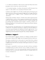
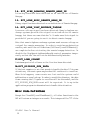
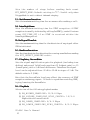
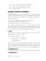
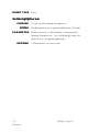
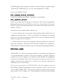
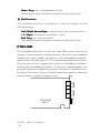
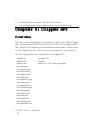
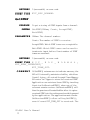
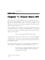
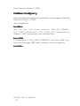
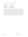
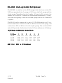
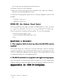
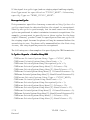
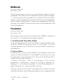
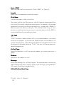
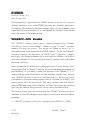
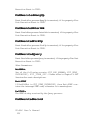
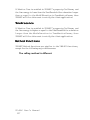
The hardware can be functionally divided into two parts: the voice
I/Opartandthelineinterfacepart. Themaincontrollerisahigh-speed
CPU 8088, with 48K bytes of voice memory for each channel. Please
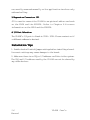
refer to the VP-894 System Block Diagram on the next page.
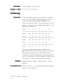
The voice I/O part of the board is the circuitry that is responsible for
voice recording and playback. The VP-894 uses the most common
method for voice digitization: 8-bit PCM at 8 KHz sampling rate.
Without any compression, this encoding method yields a data rate of
64 Kbps. But VP-894 is able to greatly reduce the data rate by using
several different compression techniques. There are four possible
voice data rates:
VP-894 User's Manual
3
8259
INTERRUPT
CONTROLLER
8088
CPU
48K RAM
VOICE
BUFFER
46K
PROGRAM
DATA
48K RAM
VOICE
BUFFER
LOCAL
48K RAM
VOICE
BUFFER
48K RAM
VOICE
BUFFER
BUS
VOICE
DSP
VOICE
DSP
VOICE
DSP
VOICE
DSP
CODEC
CODEC
CODEC
CODEC
LINE
INTERFACE
LINE
INTERFACE
LINE
INTERFACE
LINE
INTERFACE
LOCAL BUS BUFFER
PC BUS BUFFER
A0 --- A14
D0 --- D7
IOR
D0 --- D7
IOW
32K SHARED MEMORY BUFFER
MEMORY SELECTION
AND I/O CONTROL
CIRCUIT
ADAPTER & MEMORY
SELECTION AND I/O
CONTROL CIRCUIT
Figure 1: VP-894 System Block Diagram
4
Manual
VP-894 User's
IRQ
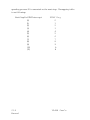
- 16 Kbps (4:1 compression)
- 9.8 Kbps (4:1 compression with silence compression)
- 8 Kbps (8:1 compression)
- 4.9 Kbps (8:1 compression with silence compression)
The higher the data rate, the better the voice quality. But a higher data
rate also means more storage space is needed for a given message
length. Note that the 9.8 Kbps and 4.9 Kbps compression rates are
estimated values only. Actual data rate may vary due to different
amount of silence within the speech.
All data (including control commands and voice data) exchanged
between VP-894 and the host computer are done through a 32K
shared memory. Data transfer is requested via system IRQ, and a
single IRQ is shared by all channels in the same host computer.
There are four 48 KB voice buffers on the VP-894, one for each channel.
Each buffer is divided into 2 equal banks and used in a ping-pong
fashion. For example, if a channel is operating at 16 Kbps (or 2 KB/
s), then each bank will need I/O service once every 12 seconds. Do not
confuse this voice buffer with the 32K shared memory.
The line interface part of VP-894 functions similar to a regular
telephone set. As a matter of fact, you may think of the host computer
as an operator, and VP-894 as his telephone set. The following
functions are supported:
- Ring Detection
- On-hook (Local Hangup) and Off-hook (Local Pickup)
- Touch Tone Detection
- Pulse Digit Detection
- Tone/Pulse Dialing
- Remote Hangup Detection
- Call Progress Monitoring (Remote Pickup Detection)
- Local Channel Interlink
Although VP-894 works well when connected to the CO (Central
Office) lines directly, it is much more powerful when connected to
a compatible private phone system (PBX). In this case, VP-894 is
VP-894 User's Manual
5
usually connected to the station side of the phone system. Depending
on the nature of the application, an inbound call may be answered by
a live operator first, then transferred manually to VP-894 for further
processing if necessary. Or, in other cases, inbound calls are
answered and processed by the VP-894 line directly without going
through a live operator.
The VP-894 has a special feature which allows two channels on the
same board to be interlinked together. Interlinked channels shared
the same audio loop and can be used to forward calls. For example,
you can call into channel #0 and tell the VP-894 to make a outboundcall
from channel #1. If channel #0 and #1 are interlinked, you will be
able to talk to the person who answers the call on channel #1.
Host Computer Consideration
When a higher sampling rate is used to obtain a better sound quality,
a more powerful host PC is required. However, it is very hard to
determine exactly what kind of computer is powerful enough for a
given application. It depends heavily on factors like the sampling rate
used, the maximum number of lines installed, the worst-case disk
overhead involved, the complexity and efficiency of the application
program, and even the DOS version on the host PC.
Therefore, the only practical way to find out how many lines a given
host computer can handle is to do some experiment. Starting with just
one or two lines, the system is tested under worst-case conditions.
More lines are then gradually put into operation, until the system
starts to overload.
There are several ways to enhance the system performance with
minimal cost. For example, using a virtue (RAM) disk to store
frequently used message files is a very good way of improving the
system response time, and hardware-based disk caching also helps
in most cases. Both techniques may significantly reduce the disk
access overhead which is usually the performance bottleneck.
However, software-based disk caching should usually be avoided
because it induces too much overhead on the host computer.
6
Manual
VP-894 User's
Phone System Considera
tion
Considerat
Not all phone systems are compatible with the VP-894. Like a fax
machine, the VP-894 needs "analog phone lines", one for each
channel.Most new phone systems offer options which turn the digital
ports into analog ports. These options go by many different names
such as "single-line port", "analog port", "OPX port", and "2500 set
compatible port".
VP-894 User's Manual
7
Har
dw
ar
e Specif
ica
tions
Hard
wa
re
Specifica
icat
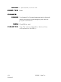
On-Board CPU
On-Board Buffer
Shared Buffer
Voice Encoding
Voice Data Rate
Voice DSP Chip
Bus Interface
Intel 8088
256KB DRAM total
32KB SRAM
u-Law PCM with compression
4.9K - 16Kbits/second
Dallas Semi 2132A
ISA 8-bit, 8MHz or faster
IRQ Requirement
I/O Address
Max. Boards/System
Line Interface
Line Connector
Start Method
Impedence
Frequency Response
Ring Detection
Loop Current
Local Phone Leads
Outbound Dialing
Inbound Reception
Crosstalk
Call Progress Monitoring
Channel Interlink
Power Requirement
Operating Temperature
Storage Temperature
Humidity
Certifications
one for all channels
300H - 302H (fixed)
16
analog
4 x RJ11
loopstart
600 Ohm/900 Ohm
300 - 3.4KHz @ 16Kbps
40 - 120Vms, 15 - 68Hz
20 - 120mA
Equipped
DTMF & Pulse
DTMF & Pulse
< 50dB
Yes
adjacent channels
+5VDC and -5VDC
0oC to +50oC
-10oC to +60oC
10% - 80% non-condensing
CE, FCC, BZT
8
Manual
VP-894 User's
Cha
pter 2: Har
dw
ar
tions
apter
Hard
wa
re
Installations
e Installa
Before installation, VP-894 boards need to be configured properly.
But before you try to configure a board, please find out the following
specifications about the host computer:
1. Does it have enough available 16-bit slots for the number of VP894 boards you are going to install?
2. Are there any devices in the system competing with VP-894 for
I/O address or IRQ? If so, can you do without those conflicting
devices or can they be moved to another I/O address or IRQ?
Otherwise VP-894 can not be installed.
3. Is the system big (available disk space) and fast (both CPU speed
and disk transfer rate) enough for the application? A 16-line setup
usually requires at least a 12 MHz 286 system with adequate disk
speed and space. However, this issue may have to be handled with
a trial-and-error approach.
4. Does the system have enough available system memory for the
application program?
Once the above requirements are met, the host computer is ready for
installation of VP-894 boards. The last step before the physical
installation is to configure the board properly.
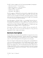
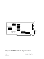
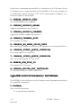
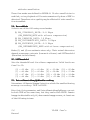
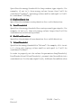
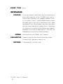
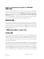
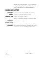
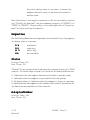
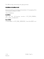
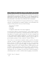
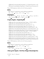
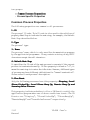
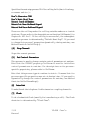
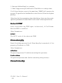
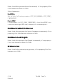
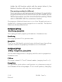
The configuration is fairly simple. Basically every VP-894 board in
the system should have an unique board number and a common
shared-memory location. Then an IRQ is chosen for all the boards
in the system. Another setting is to enable/disable the local phone
function.
VP-894 User's Manual
9
JP6
W14 16 18 20
W13 15 17 19
W10
W2
W12
W4
W9
W1
W11
VP-894SMD
REV. A
W3
W 5
3
2
1
0
6
7 8
ON
1
IRQ 3 5
7 9
8
S1
Figure 2: VP-894 Switch and Jumper Locations
10
Manual
VP-894 User's
LED3
LED2
LED1
LED0
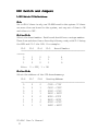
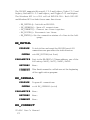
DIP Switch and Jumpers
1.
DIP Switch S1 Definitions
.DIP
S1-1:
Set to ON if there is only one VP-894 board in the system. If there
are more than one board in the system, set any one of them to ON
and others to OFF.
S1-2 to S1-5:
Select the board number. Each board should have a unique number.
These four switches form a four-digit binary code, with S1-2 being
the MSB and S1-5 the LSB. For example:
S1-2 S1-3 S1-4 S1-5 Board Number
--------------------------------------------------------------------------------------0
1
0
0
4
0
0
1
1
3
1
0
0
1
9
Note: 0 = OFF, 1 = ON
S1-6 to S1-8:
Select the address of the 32K shared-memory:
S1-6 S1-7 S1-8 Starting Address
----------------------------------------------------------------------------0
0
0
C000 - C7FF
0
0
1
C800 - CFFF
0
1
0
D000 - D7FF
0
1
1
D800 - DFFF
1
0
0
E000 - E7FF
1
0
1
E800 - EFFF
1
1
0
A000 - A7FF
1
1
1
A800 - AFFF
VP-894 User's Manual
11
2.
.Jumper
Jumper Settings
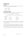
W5 to W8:
Select a common IRQ for all VP-894 boards in the same system. One
and only one jumper must be ON (installed):
W5
W6
W7
W8
ON
ON
ON
ON
=
=
=
=
IRQ3
IRQ5
IRQ7
IRQ9
W1 to W4, W9 to W20:
These jumpers are used to enable/disable the local phone function.
Note that each line can be independently configured.
Local Phone Disable Local Phone Enable
------------------------------------------------------------------------------------------------LINE 1:
W3, W13
W11, W14
LINE 2:
W1, W15
W9, W16
LINE 3:
W4, W17
W12, W18
LINE 4:
W2, W19
W10, W20
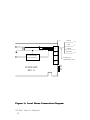
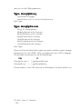
The local phone should be disabled if the application is to detect and
answer inbound calls. If the local phone is enabled, the incoming ring
can not be detected.
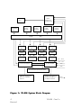
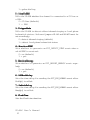
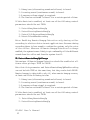
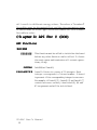
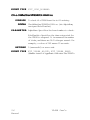
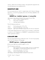
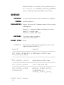
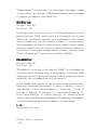
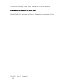
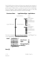
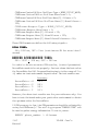
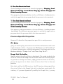
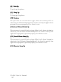
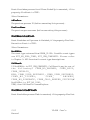
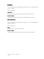
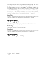
The local phone is usually enabled when the application calls for online conversation monitoring and/or recording. In this case the
VP-894 is connected to both a outside line and a local phone. The
following diagram shows how to make the connections. Since the
incoming ring can no longer be detected by the computer, the calls
12
Manual
VP-894 User's
BLACK
RED
LOCAL PHONE
PICK-UP DETECT
3
GREEN
2
YELLOW
1
LED3
LED2
LED1
LED0
Figure 3: Local Phone Connection Diagram
VP-894 User's Manual
13
L1
L2
L4
4-WIRE RJ-11
TELEPHONE CORD
0
VP-894SMD
REV. A
L3
are usually answered manually or the application involves only
outbound calling.
3.
.Expansion
Expansion Connector JP1
JP1 is used to connect the VP-894 to an optional add-on card such
as the EX24 and the EX2424. Refer to Chapter 8 for more
information on the EX24 and the EX2424.
4.
.I/O
I/O Port Selection
The VP-894's I/O port is fixed at 300H - 302H. Please contact us if
a different address is desired.
Installation Tips
1. Double-check all switch/jumper settings before installing a board.
Incorrect settings may cause damages to the board.
2. Make sure there is no IRQ or I/O address conflicts in the system.
The IRQ and I/O address used by the VP-894 can not be shared by
any other devices.
14
Manual
VP-894 User's
3. Handle boards with care. Discharge yourself first and avoid
touching any components on the board as much as possible.
Cha
pter 3: API Ov
er
vie
w
ap
Ove
rvie
view
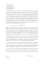
The API considers each line as a "channel". The mapping between
lines and channels is as following:
LINE 1, 2, 3, 4 on board #0 is channel #0, #1, #2, #3
LINE 1, 2, 3, 4 on board #1 is channel #4, #5, #6, #7
.........................................
LINE m on board #n is channel #(4n+m-1)
Therefore, each line in the system should have a unique channel
number if boards in the same system are configured with different
board numbers.
There are two types of functions in the API: event-driven and non
event-driven.
The event-driven type functions usually take a long time to complete,
therefore the channel will remain busy for a while even after the
function returns. The results or error codes are then posted in the
event queue when the function actually finishes. For example,
calling the Play() function only activates the playback of a message
file. The function quickly returns but the channel remain busy
(playing message) until something happens (e.g. the end of fileis
reached). At that time the result (e.g. playback finished normally) is
posted in the event queue and the channel goes back to idle.
VP-894 User's Manual
15
The non event-driven type functions usually takes a short time to
complete, and the job is always done when the function returns. This
type of functions does not update the event queue.
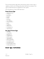
The following is a list of API functions:
Event-Driven Type
- SetCtrlParam()
- PickUp()
- HangUp()
- Flash()
- Play()
- Record()
- GetDTMF()
- FlushDTMF()
- Dial()
- StopCh()
- CallLocal()
- CallRemote()
- CallBeeper()
Non Event-Driven Type
- Init894()
- Close894()
- GetEvent()
- FlushEvent()
- GetEnergy()
- InsertEvent()
- GetCtrlParam()
- GetCPMParam()
- SetCPMParam()
- GetHungUpParam()
- SetHungUpParam()
Ev
ent Type Def
initions
Event
Defi
16
Manual
VP-894 User's
The API894.H include file defines the following "Event Types".
These events are inserted into the event queue by event-driven type
functions upon completion of their tasks.
1. EVT_EOP_NORMAL
Operation is completed normally.
2. EVT_DTMF_INTERCEPT
Current operation is interrupted by remote DTMF input.
3. EVT_TIME_OUT
Current operation is terminated due to time out.
4. EVT_ENDOF_STOP
StopCh() is completed.
5. EVT_INTRN_QUEUE_OVERFLOW
Internal event queue overflow. This is because events are not
processed fast enough. When this happens, the system terminates all
operations,resetsitselfandre-initializesallchannels.
6. EVT_DETECT_RING
(N/A when local phone is enabled)
Telephone ring is detected.
7. EVT_LOCAL_PHONE_PICKED_UP
(N/A when local phone is disabled)
Local phone is picked up.
8. EVT_LOCAL_PHONE_HUNG_UP
(N/A when the local phone is disabled)
Local phone is hung up.
9. EVT_DETECT_DTMF
A valid DTMF is received.
10. EVT_REPORT_ENERGY
An energy report is received.
VP-894 User's Manual
17
11. EVT_PCMIO_ERROR
File I/O error for the current record and playback function. When
this happens, the current operation continues but may be stopped by
calling StopCh().
12. EVT_NO_DIAL_TONE
Outbound calling aborted due to no dial tone.
13. EVT_CPM_COMPLETE
Outbound calling completed with one of the following CPM results
(defined in API894.H) if CPM was enabled. The CPM result is
stored in the Data field of structure typeEvent. The data stored in
typeEvent can be retrieved by calling function GetEvent().
(1) CPMR_NO_ANSWER
Normal ringback was detected, but not answered within the
time period set in WaitAnswerDuration control parameter.
(2) CPMR_BUSY
Line busy was detected.
(3) CPMR_INVALID_NUM
The number was invalid.
(4) CPMR_USER_DEFINED1, CPMR_USER_DEFINED2
User defined CPM cadence #1 or #2 was detected.
(5) CPMR_NO_SIGNAL
No signal was detected within the time period set in the
NoSignalTimeOut control parameter.
(6) CPMR_ANSWER
The call has been answered.
(7) CPM_NO_RINGBACK
No ringback was detected within the time period set in the
WaitAnswerDuration control parameter.
(8) CPMR_CALL_BEEPER_SUCCESS
Pager calling was successful.
18
Manual
VP-894 User's
14. EVT_LINE_ROARING_REMOTE_HANG_UP
A roaring sound has been detected as an indication of Remote
Hangup.
15. EVT_LINE_BUSY_REMOTE_HANG_UP
A busy signal has been detected as an indication of Remote Hangup.
16. EVT_LINE_VOLT_REVERSE_TOGGLE
A reverse voltage signal has been detected. Many telephone exchange systems provide this signal as an indication of remote
hangup, but there are some that don't. So make sure this signal is
provided if you are going to use it to detect remote hangup.
Note that some telephone exchange systems send reverse voltage as
a signal for remote answering. In order to avoid wrong detection
results, wait until the call functions (CallLocal() and CallRemote())
are complete before activating the remote hangup detection. Or
disable the StopOperationRemoteHangUp control parameter temporarily so that the line will not be disconnected by mistake.
17. EVT_LINE_SILENT
A minimum period of silence on the line has been detected.
18. EVT_DISPOSE_PCM_DATA
If the host computer is not fast enough to handle the data I/O in some
situations, the event queue may become full and start to overflow.
When this happens, some events are lost and the system could
malfunction or even lock-up. In order to avoid this disaster, the data
frame causing the I/O queue to overflow will be discarded, and the
EVT_DISPOSE_PCM_DATA event will be reported. It is up tothe
application program to determine how to handle this situation.
initions
ror
Defi
Err
or Code Def
Except for Close894() and FlushEvent(), all other functions in the
API will return an integer as a result. This integer will be "0" if the
VP-894 User's Manual
19
function is executed successfully, otherwise it will be one of the
following error codes defined in the API894.H. The only exception
is GetEvent() which returns a "0" if the event queue is empty, or a
non-zero value if successful.
1. ERR894_INVALID_FUNC
The called function is invalid.
2. ERR894_INVALID_PARAM
Supplied parameters are invalid.
3. ERR894_INVALID_CHANNEL
Supplied channel number is invalid.
4. ERR894_CHANNEL_BUSY
The channel is busy.
5. ERR894_NO_MORE_VOICE_DATA
When the Play() function is called, file pointer is at the end of file.
6. ERR894_EVENT_QUEUE_OVERFLOW
The event queue is overflow.
7. ERR894_PCMIO_QUEUE_OVERFLOW
The voice data queue is overflow.
8. ERR894_PCM_FILE_IO
Voice data file I/O error.
9. ERR894_DRIVER_NOT_INSTALLED
VP-894 device driver is not installed.
typeCPB Contr
arameter Def
initions
Contro
Parameter
Defi
olP
The API894.H also defines the following control parameters within
the typeCPB structure:
1. DialMode
Sets the dialing mode.
0 = tone dialing (default)
20
Manual
VP-894 User's
1 = pulse dialing
2. LineToPBX
Tells the VP-894 whether the channel is connected to a CO line or
a PBX.
0 = CO line (default)
1 = PBX
3. TriggerMode
Tells the VP-894 to detect either inbound ringing or local phone
hookswitch status. On-board jumpers W1-W4 and W9-W20 must be
set accordingly.
0 = detect inbound ringing (default)
1 = detect local phone hookswitch status
4. MonitorDTMF
Sets whether to generate an EVT_DETECT_DTMF event when a
valid DTMF is received.
0 = no (default)
1 = yes
5. MonitorEnergy
Sets whether to generate an EVT_REPORT_ENERGY event regularly.
0 = no (default)
1 = yes
6. OffHookDelay
Sets the time delay for sending the EVT_EOP_NORMAL event after
PickUp() is called.
7. OnHookDelay
Sets the time delay for sending the EVT_EOP_NORMAL event after
HangUp() is called.
8. FlashTime
Sets the flash time duration.
VP-894 User's Manual
21
DIGIT: 2
T2
T1
DIGIT: 1
T2
T3
T2
DIGIT: 3
T3
T2
T1
T2
T1
T2
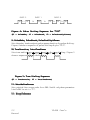
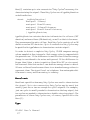
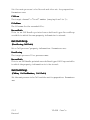
Figure 4: Pulse Dialing Sequence for "213"
(T1 = PulseMake, T2 = PulseBreak, T3 = PulsePostDigitPause)
9. PulseMake, PulseBreak, PulsePostDigitPause
Sets the make, break and post-pulse pause duration for pulse dialing.
Figure 4 shows a sequence of pulse dialing digits "213".
10. ToneDuration, InterTonePause
Sets tone and inter-tone
pause
for tone
T1
T2 duration
T1
T2
T1dialing. Figure 5
shows a sequence of tone dialing.
Figure 5: Tone Dialing Sequence
(T1 = ToneDuration, T2 = InterTonePause)
11. OutsideLineAccess
Sets outside line access code for a PBX. Useful only when parameter
LineToPBX is set to "1".
12. RingsToAnswer
22
Manual
VP-894 User's
Sets the number of rings before sending back event
EVT_DETECT_RING. Default setting is "1". Useful only when
TriggerMode is set to detect inbound ringing.
13. WaitAnswerDuration
Sets the maximum waiting time for an answer after making a call.
14. InterDigitPause
Sets the maximum waiting time for DTMF reception. A DTMF
reception is usually initiated by calling GetDTMF(), and will return
event EVT_TIME_OUT if no DTMF is received within the
InterDigitPause period.
15. NoSignalTimeOut
Sets the maximum waiting time for the detection of any signal after
CPM is initiated.
16. MaxRoarDuration
Sets the time duration for detecting the roaring sound before sending
the EVT_DETECT_ROARING event.
17. PlayGain, RecordGain
Sets the signal amplification gain for playback (including tone
dialing) and record. Valid levels are from +10 (highest gain) to -10
(lowest gain), with a 3 dB level difference. Therefore the signal
level can be adjusted from -30 dB to 30 dB in steps of 3 dB. The
default value is 0 (0 dB).
Note that the RecordGain level may affect the accuracy of DTMF
reception and energy report. If there is a problem receiving DTMF,
trying lowering the RecordGain.
18. PlayMode
Selects one of the following playback modes:
(1) PM_HIGHER_SAMPLING: 16/9.8 Kbps
(2) PM_HIGHER_SAMPLING_ECHO_CANCEL: 16/9.8
Kbps with echo cancellation
(3) PM_LOWER_SAMPLING: 8/4.9 Kbps
(4) PM_LOWER_SAMPLING_ECHO_CANCEL: 8/4.9 Kbps
VP-894 User's Manual
23
with echo cancellation
These four modes are defined in API894.H. If echo cancellation is
enabled, voice playback will be mute momentarily when a DTMF is
detected. Therefore voice quality may be affected if echo cancellation is enabled.
19. RecordMode
Selects one of the following record modes:
(1) RM_STANDARD_RATE: 9.8 Kbps
(RM_PREMIUM_RATE with silence compression)
(2) RM_PREMIUM_RATE: 16 Kbps
(3) RM_INTERMEDIATE_RATE: 8 Kbps
(4) RM_EXTENDED_RATE: 4.9 Kbps
(RM_INTERMEDIATE_RATE with silence compression)
Modes (1) and (4) are estimate rates only. Their actual data rates
depend on message contents (how much silence) and OffThreshold
(how silent is the silence).
20. OffThreshold
Sets the threshold level for silence compression. Valid levels are
from 0 to 15:
[0] = -50 dBm
[1] = -49 dBm
[2] = -47 dBm
[3] = -44 dBm
[4] = -42 dBm
[5] = -40 dBm
[6] = -38 dBm
[7] = -35 dBm
[8] = -32 dBm
[9] = -29 dBm
[10] = -26 dBm
[11] = -23 dBm
[12] = -20 dBm
[13] = -17 dBm
[14] = -14 dBm
[15] = -11 dBm
21. DetectRemoteHangUpWhenRecording
Determines if Remote Hangup Detection should be enabled during
message recording: TRUE orFALSE.
Note that this parameter and DetectRemoteHangUpAlways can not
be both TRUE at the same time, but they can be both FALSE. Remote
hangup is detectable only if, when remote hangup occurs, at least one
of the following is true:
24
Manual
VP-894 User's
1. A busy tone (alternating sound and silence) is heard.
2. A roaring sound (continuous sound) is heard.
3. A reverse-voltage signal is received.
4. The line has recorded "silence" for a certain period of time.
If this function is enabled, at least one of the following control
parameters should be set TRUE:
1. DetectBusyRemoteHangUp
2. DetectRoaringRemoteHangUp
3. DetectVoltReverseRemoteHangUp
4. DetectSilentWhenRecording
Note: Enabling Remote Hangup Detection only during caller
recording is a better choice in most applications. Because during
recording there is less sound to confuse the system, only the voice
of the caller. Whereas if Remote Hangup Detection is always
enabled, the system is more likely to get confused by all the different
sounds from the caller and from the system itself.
22. DetectRemoteHangUpAlways
Determines if Remote Hangup Detection should be enabled at all
times after pickup: TRUE or FALSE.
Note that this parameter and DetectRemoteHangUpWhenRecording
can not be both TRUE at the same time, but they can be both FALSE.
Remote hangup is detectable only if, when remote hangup occurs,
at least one of the following is true:
1. A busy tone (alternating sound and silence) is heard.
2. A roaring sound (continuous sound) is heard.
3. A reverse-voltage signal is received.
4. The line has recorded "silence" for a certain period of time.
If this function is enabled, at least one of the following control
parameters should be set TRUE:
1. DetectBusyRemoteHangUp
2. DetectRoaringRemoteHangUp
VP-894 User's Manual
25
3. DetectVoltReverseRemoteHangUp
4. DetectSilentWhenRecording
Note: Avoid using this function as much as possible, because the
system is more likely to get confused when Remote Hangup
Detection is always enabled. If you must use this function, test your
application program under different line (noise) conditions.
23. DetectBusyRemoteHangUp
Determines if busy signal should be detected as an indication for
Remote Hangup: TRUE or FALSE.
24. DetectRoaringRemoteHangUp
Determines if roaring sound should be detected as an indication for
Remote Hangup: TRUE or FALSE.
25. DetectVoltReverseRemoteHangUp
Determines if reverse voltage signal (sent from the Central Office)
should be detected as an indication for Remote Hangup: TRUE of
FALSE. The reverse voltage signal may not be provided in some
areas. Also, if the system is not connected directly to the Central
Office, then the reverse voltage signal may not be detectable.
26. DetectSilentWhenRecording
Determines if "silent during recording" should be detected as an
indication for Remote Hangup: TRUE or FALSE. The minimum
silence duration and the energy threshold for silence are specified in
Hangup Parameters as MinSilentDuration and SilentThreshold.
27. StopOperationRemoteHangUp
Determines what the system should do when a Remote Hangup is
detected. If set to TRUE, the system will hang up the line and go back
to idle automatically. If set to FALSE, the system will just issue one
of the following events:
26
Manual
VP-894 User's
EVT_LINE_ROARING_REMOTE_HANG_UP
EVT_LINE_BUSY_REMOTE_HANG_UP
EVT_LINE_VOLT_REVERSE_TOGGLE
EVT_LINE_SILENT
HangUp P
arameter Def
initions
Parameter
Defi
The HangUp Parameters define the characteristics of the disconnect
signal on the telephone line after the caller hangs up. They are used
for Remote Hangup Detection purpose. Three types of disconnect
signals are supported:
1.Busy-Cadence Type: alternating silence and sound.
2.Roaring-Sound Type: continuous sound.
3.Continuous-Silence Type: continuous silence.
The following parameters define the above three signals. Note that
when selecting a "threshold" value (e.g. BusyThreshold) you must
take the RecordGain into consideration, because the same signal will
yield different energy values for different RecordGain.
1. Busy
Busy defines the cadence of a busy signal in a data structure of
typeHungUpBusy as the following:
struct _tagHungUpBusy{
int
Varieties;
typeDutyDuration Cadence[5];
} typeHungUpBusy;
Where Varieties specifies how many different kind of busy signals
are to be detected. Maximum value is 5. Cadence[] defines the
cadence information of the different busy signals. Please refer to
Appendix A: CPM Principles for descriptions on typeDutyDuration.
2. MinBusyDuration
Specifies the minimum busy-cadence duration for a valid detection.
3. BusyThreshold
VP-894 User's Manual
27
Specifies the energy threshold for busy-cadence type signals. For
example, if set to 5, then energy values larger than 5 will be
considered "on-duty", and energy values smaller and equal to 5 will
be considered "off-duty".
4. MinRoarDuration
Specifies the minimum roaring duration for a valid detection.
5. RoarThreshold
Specifies the energy threshold for roaring-sound type signals. For
example, if set to 5, then only energy values larger than 5 will be
considered as valid roaring-sound.
6. MinSilentDuration
Specifies the minimum silence duration for a valid detection.
7. SilentThreshold
Specifies the energy threshold for "silence". For example, if it is set
to 5, then only energy values smaller and equal to 5 will be
considered "silence".
In order to properly set the values for parameters BusyThreshold,
RoarThreshold and SilentThreshold, you must take RecordGain into
consideration. For the same signal level, different RecordGain value
28
Manual
VP-894 User's
will result in different energy values. Therefore a "standard"
RecordGain must be determined first and the other parameters must
be tested under the actual application environment with this standard
RecordGain value.
Cha
pter 4: API For C (DOS)
ap
API Functions
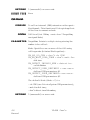
Init894
PURPOSE
This function must be called to initialize the board
before any other function can be called. It clears
the event queue and terminates all current operations,ifany.
SYNTAX Init894(int*Install)
P A R A M E T E R Install: Points to a array of 16 integers. Each
integer corresponds to a board number. A board
is present if its corresponding integer is non-zero.
Forexample,ifInstall[2],Install[4]andInstall[7]
contain non-zero values, then board #2, #4 and
#7 are present and will be initialized.
VP-894 User's Manual
29
RETURNS 0 (successful) or error code
EVENT TYPE None.
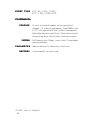
Close894
PURPOSE
To stop operations on all channels in the system
and return them to the idle mode.
SYNTAX Close894()
RETURNS None
30
Manual
VP-894 User's
P A R A M E T E R None
EVENT TYPE None
GetCtr
lP
aram
GetCtrl
Param
PURPOSE
To get the control parameter for the specified
channel.
SYNTAX GetCtrlParam(int ChNum, typeCPB *CtrlParam)
P A R A M E T E R CtrlParam: Points to a typeCPB structure which is
defined in API894.H. See section Control Parameter Definition in Chapter 3 for more details.
VP-894 User's Manual
31
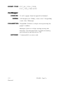
RETURNS 0 (successful) or error code
EVENT TYPE None
SetCtr
aram
SetCtrl
Param
lP
PURPOSE
To set the control parameter for the specified
channel.
SYNTAX SetCtrlParam(int ChNum, typeCPB *CtrlParam)
P A R A M E T E R CtrlParam: Points to a typeCPB structure which is
defined in API894.H. See section Control Parameter Definition in Chapter 3 for more details.
32
Manual
VP-894 User's
RETURNS 0 (successful) or error code
EVENT TYPE EVT_EOP_NORMAL
PickUp
PURPOSE
To go off-hook on the specified channel.
SYNTAX PickUp(int ChNum)
P A R A M E T E R None
VP-894 User's Manual
33
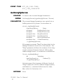
RETURNS 0 (successful) or error code
EVENT TYPE EVT_EOP_NORMAL
HangUp
PURPOSE
To go on-hook on the specified channel.
SYNTAX HangUp(int ChNum)
P A R A M E T E R None
34
Manual
VP-894 User's
RETURNS 0 (successful) or error code
EVENT TYPE EVT_EOP_NORMAL
Flash
PURPOSE
To do a hookswitch flash on the specified channel, for a duration specified by control parameter
FlashTime.
SYNTAX Flash(int ChNum)
P A R A M E T E R None
VP-894 User's Manual
35
RETURNS 0 (successful) or error code
EVENT TYPE EVT_EOP_NORMAL
Play
PURPOSE
To play a voice file on the specified channel.
DTMF queue is also cleared.
SYNTAX Play(int ChNum, int Handle, long Length,
unsigned AcceptDTMF)
P A R A M E T E R Handle: The file handle of the voice file.
Length: The number of bytes to play. Playback
always starts from wherever the file handle points
to in the file. It will continue to the end of file if
Length is 0 or exceeds remaining file length.
Use StopCh() to stop a playback. If the file handle
has not been moved since a playback is stopped,
the playback may be resumed from where it is
stopped by calling Play() again.
AcceptDTMF: Defines which DTMF tone(s) can
be used to stop the playback. It may contain any
number of the following constants (defined in
API894.H), bitwise ORed ("|") together.
E_DTMF0, E_DTMF1, E_DTMF2, E_DTMF3,
E_DTMF4, E_DTMF5, E_DTMF6, E_DTMF7,
E_DTMF8, E_DTMF9, E_DTMFa, E_DTMFb,
E_DTMFc, E_DTMFd, E_DTMF_ASTERISK,
E_DTMF_POUND
RETURNS 0 (successful) or error code. If less than 255, the
error code is actually the one returned from DOS.
EVENT TYPE EVT_EOP_NORMAL,
36
Manual
VP-894 User's
EVT_DTMF_INTERCEPT,
EVT_PCMIO_ERROR
Record
PURPOSE
To record a voice file on the specified channel.
DTMF queue is also cleared.
SYNTAX Record(int ChNum, int Handle, unsigned Length,
unsigned AcceptDTMF)
P A R A M E T E R Handle: The file handle of the voice file.
Length: The number of seconds to record.
Recording always starts from wherever the file
handle points to in the file. It will continue
indefinitely (until stopped by an acceptable DTMF
tone) if Length is set to 0.
AcceptDTMF: Defines which DTMF tone(s) can
be used to stop the recording. It may contain any
number of the following constants (defined in
API894.H), bitwise ORed ("|") together.
E_DTMF0, E_DTMF1, E_DTMF2, E_DTMF3,
E_DTMF4, E_DTMF5, E_DTMF6, E_DTMF7,
E_DTMF8, E_DTMF9, E_DTMFa, E_DTMFb,
E_DTMFc, E_DTMFd, E_DTMF_ASTERISK,
E_DTMF_POUND
RETURNS 0 (successful) or error code
EVENT TYPE EVT_EOP_NORMAL,
VP-894 User's Manual
37
EVT_DTMF_INTERCEPT,
EVT_PCMIO_ERROR.
GetDTMF
PURPOSE
To get a string of DTMF or pulse input on the
specified channel.
SYNTAX GetDTMF(int ChNum, char *Buffer, unsigned
Count, unsigned AcceptDTMF, unsigned
ExitDTMF)
P A R A M E T E R Buffer: Points to the code buffer where received
codes will be stored. The code buffer must be at
least one character larger than Count. The extra
character is for the NULL character at the end of
the ASCII string.
Count: The number of codes to be received.
AcceptDTMF: Defines which codes are acceptable. It may contain any number of the following
constants (defined in API894.H), bitwise ORed
("|") together.
E_DTMF0, E_DTMF1, E_DTMF2, E_DTMF3,
E_DTMF4, E_DTMF5, E_DTMF6, E_DTMF7,
E_DTMF8, E_DTMF9, E_DTMFa, E_DTMFb,
E_DTMFc, E_DTMFd, E_DTMF_ASTERISK,
E_DTMF_POUND
ExitDTMF: Defines which codes can be used to
stop DTMF input before Count number of codes
are received. It may contain 0, 1 or several of the
above constants, bitwise ORed ("|") together.
RETURNS 0 (successful) or error code
38
Manual
VP-894 User's
EVENT TYPE EVT_EOP_NORMAL,
EVT_DTMF_INTERCEPT, EVT_TIME_OUT
FlushDTMF
PURPOSE
To clear the DTMF queue on the specified
channel.
SYNTAX FlushDTMF(int ChNum)
RETURNS 0 (successful) or error code
VP-894 User's Manual
39
P A R A M E T E R The only parameter is the channel number ChNum.
EVENT TYPE EVT_EOP_NORMAL
Dial
PURPOSE
To dial a string of digits on the specified channel.
SYNTAX Dial(int ChNum, char *String)
P A R A M E T E R String: Points to the string of digits to be dialed.
40
Manual
VP-894 User's
RETURNS 0 (successful) or error code
EVENT TYPE EVT_EOP_NORMAL
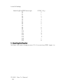
GetEnergy
PURPOSE
To get the energy report on the specified channel.
If (control parameter) MonitorEnergy is set to 1,
then (event) EVT_REPORT_ENERGY will
occur once every 240 ms. The energy report is 30
bytes of energy levels in dBmo (8 ms apart), and
defined as following:
Value
0 2 4 5 6 7 8
-----------------------------------------------------------Level
-48 -45 -42 -39 -36 -33 -30
Value
9 10 11 12 13 14 15
-----------------------------------------------------------Level
-27 -24 -21 -18 -15 -12 -9
Value
16 17 18 19 20 21
-----------------------------------------------------------Level
-6 -3 0 3 6 9
There are some energy report examples in
Appendix B. Note that the energy values indicate
the signal strength on the line under certain
conditions. Factors that affect the energy values
are the condition of the line (amount of noise) and
the value of (control parameter) RecordGain.
SYNTAX GetEnergy(int ChNum, unsigned char *const
Buffer)
P A R A M E T E R Buffer: Points to a 30-byte buffer where energy
report is to be stored.
VP-894 User's Manual
41
RETURNS 0 (successful) or error code
EVENT TYPE None
StopCh
PURPOSE
To stop current operation (if any) on the specified
channel. If the channel is playing a file when it is
stopped, the playback can be resumed from where
it is stopped by calling Play() again, assuming the
file pointer has not been moved since.
SYNTAX StopCh(int ChNum)
P A R A M E T E R None
42
Manual
VP-894 User's
RETURNS 0 (successful) or error code
EVENT TYPE EVT_ENDOF_STOP
GetEv
ent
GetEvent
PURPOSE
To get a new event from the event queue.
SYNTAX GetEvent(typeEvent *EvtBuf)
P A R A M E T E R EvtBuf: Points to a structure of typeEvent (defined
in API894.H). Members in this structure are:
Issuer: Number of the channel sending this event.
Type: Type of this event.
Data: Contains different kind of data based on the
event type: EVT_DTMF_INTERCEP
& EVT_DETECT_DTMF = the DTMF code;
EVT_PCMIO_ERROR = the DOS error code;
EVT_INTRN_QUEUE_OVERFLOW =
ERR894_EVENT_QUEUE_OVERFLOW or
ERR894_PCMIO_QUEUE_OVERFLOW;
Other Events = not defined.
RETURNS 0 (event queue is empty)
VP-894 User's Manual
43
non-zero (successful)
EVENT TYPE None
Inser
tEv
ent
Insert
vent
PURPOSE
To insert a user-defined event into the event
queue. Events 0xA0 to 0xFF are reserved for
he who wants to define his own event types.
SYNTAX InsertEvent(typeEvent *EvtBuf)
P A R A M E T E R EvtBuf: Points to a structure of typeEvent (defined
in API894.H). See GetEvent for more details.
44
Manual
VP-894 User's
RETURNS 0 (successful) or error code
EVENT TYPE None
FlushEv
ent
FlushEvent
PURPOSE
To clear the event queue.
SYNTAX FlushEvent(void)
P A R A M E T E R None
VP-894 User's Manual
45
RETURNS None
EVENT TYPE None
GetCPMP
aram
GetCPMParam
PURPOSE
To get the CPM parameters.
SYNTAX GetCPMParam(typeCPMParam *CPMParam)
P A R A M E T E R CPMParam: Points to a buffer of typeCPMParam.
typeCPMParam contains CPM parameters for
central office, PBX and pager. It is defined as:
struct_tagCPMParam {
typeCadenceType
typeCadenceType
typeCadence
} typeCPMParam;
CentralOffice;
PrivateSystem;
Beeper;
typeCadenceType is defined as:
struct_tagCadenceType {
typeCadence Ring;
typeCadence Busy;
typeCadence InvalidNum;
typeCadence DialTone;
typeCadence UserDefined1;
typeCadence UserDefined2;
} typeCadenceType;
typeCadence is defined as:
struct_tagCadence {
unsigned char WaveCount:3;
unsigned char Type:1;
unsigned char :4;
unsigned char RecognizeCycle;
typeDutyDuration Wave[6];
} typeCadence;
46
Manual
VP-894 User's
RETURNS None
EVENT TYPE None
SetCPMP
aram
SetCPMParam
PURPOSE
To set the CPM parameters.
SYNTAX SetCPMParam(const typeCPMParam
*CPMParam)
P A R A M E T E R CPMParam: Points to a buffer of typeCPMParam
See (function) GetCPMParam for more details.
VP-894 User's Manual
47
RETURNS 0 (successful) or error code
EVENT TYPE None
CallLocal
PURPOSE
To call an internal (PBX) extension on the specified channel. This function will do a pick-up first
if the line is current on-hook.
SYNTAX CallLocal(int ChNum, const char *TargetNum,
unsigned Mode)
P A R A M E T E R TargetNum: Points to a digit string storing the
number to be called.
Mode: Specifies one or more of the following
calling modes (bitwise ORed together):
CM_NO_DO_CPM = don't do CPM
CM_NO_WAIT_DIAL_TONE = don't wait for
dialtone
CM_DETECT_INVALID_NUM = detect invalid number
CM_DETECT_USER_DEFINED1 = use userdefined CPM parameters #1
CM_DETECT_USER_DEFINED2= use userdefined CPM parameters #2
The default Mode (Mode = 0) is
- do CPM (use PrivateSystem CPM parameters),
- wait for dial tone,
- don't detect invalid number,
RETURNS 0 (successful) or error code
48
Manual
VP-894 User's
EVENT TYPE EVT_NO_DIAL_TONE,
EVT_CPM_COMPLETE
CallRemote
PURPOSE
To call an outside number on the specified
channel. If (control parameter) LineToPBX is set
to "1", the system will dial (control parameter)
OutsideLineAccess code first. This function will
do a pick-up first if the line is current on-hook.
SYNTAX CallRemote(int ChNum, const char *TargetNum,
unsigned Mode)
P A R A M E T E R Same as defined in (function) CallLocal.
RETURNS 0 (successful) or error code
VP-894 User's Manual
49
EVENT TYPE EVT_NO_DIAL_TONE,
EVT_CPM_COMPLETE
CallBeeper
PURPOSE
To call a pager from the specified channel.
SYNTAX CallBeeper(int ChNum, const char *TargetNum,
const char *Message)
P A R A M E T E R TargetNum: Points to a digit string storing the
pager's number.
Message: Points to a digit string storing the
message. The message must include necessary
prolog and/or epilog such as "#".
RETURNS 0 (successful) or error code
50
Manual
VP-894 User's
EVENT TYPE EVT_NO_DIAL TONE,
EVT_CPM_COMPLETE
GetHungUpP
aram
GetHungUpParam
PURPOSE
To obtain the current Hangup Parameters.
SYNTAX GetHungUpParam(typeHungUpParam *Param)
P A R A M E T E R The current Hangup Parameters are copied into a
buffer pointed to by Param. Its structure is:
struct_tagHungUpParam{
typeHungUpBusy
Busy;
unsigned
MinBusyDuration;
unsigned
MinRoarDuration;
unsigned char BusyThreshold;
unsigned char RoarThreshold;
unsigned
MinSilentDuration
unsigned char SilentThreshold;
} typeHungUpParam;
All parameters except "Busy" are described in the
Hangup Parameters section in this manual. The
"Busy" parameter defines the cadence of the busy
signal returned from the Central Office when
remote hangup occurs. Its structure is defined as:
Struct_tagHungUpBusy{
int
Varieties;
typeDutyDuration
Cadence[5];
} typeHungUpBusy;
Varieties specifies how many different kinds of
"busy" signal are valid as remote hangup signals,
and Cadence [] contains definitions for them.
Max. value for Varieties is 5.
RETURNS None
VP-894 User's Manual
51
EVENT TYPE None
SetHungUpP
aram
SetHungUpParam
PURPOSE
To set up the Hangup Parameters.
SYNTAX SetHungUpParam (typeHungUpParam *Param)
P A R A M E T E R Param: Points to a data buffer containing the
Hangup Parameters. See GetHungUpParam for
definition of typeHungUpParam.
RETURNS 0 (successful) or error code
52
Manual
VP-894 User's
EVENT TYPE None
SetInterLink
PURPOSE
To set up channel interlink. Any two consecutive
even/odd channels on the VP-894 board can be
interlinked together, for example channel 0 and
1, or channel 2 and 3. Interlinked channels share
the same audio loop like a conference call. When
two channels are interlinked, only the even channel can record and detect energy level. Therefore
it is better to receive calls from an even channel
and make calls from an odd channel. This way the
hangup detection will be more accurate.
SYNTAX SetInterLink (int ChNum, int Connect)
P A R A M E T E R Connect: Controls the status of the interlink;
0 turns it off, non-zero turns it on.
RETURNS 0 (successful) or error code
VP-894 User's Manual
53
EVENT TYPE EVT_EOP_NORMAL
Chec
kWhetherVP894StillAliv
e
CheckWhetherVP894StillAliv
kWhetherVP894StillAlive
PURPOSE
To check if a VP894 board is still working.
SYNTAX CheckWhetherVP894StillAlive (int AdptrNum,
unsigned EchoTimeOut)
P A R A M E T E R AdptrNum: Specifies the board number to check.
EchoTimeOut: Specifies the time-out period for
the VP894 to respond. It is measured in number
of ticks, and there are 18.2 ticks per second. For
example, a value of 182 means 10 seconds.
RETURNS 0 (successful) or error code
EVENT TYPE EVT_VP894_ALIVE, EVT_VP894_DEAD
(Member issuer of typeEvent indicates the VP894's
54
Manual
VP-894 User's
board number sending these events.)
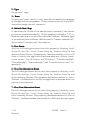
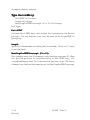
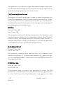
Pulse Digit Detection
Pulse digit detection function was added to API version 2.6x and up,
for use in areas where touch tone dialing is not widely available.
Pulse digit detection is very difficult because pulse digits coming
from different Central Office may have different timing parameters
and different signal levels. It is almost impossible to come up with
auniversalsetofparameterstocharacterizeallpossiblepulsedigits.
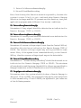
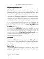
Therefore, the VP-894 adopted the "learn-per-call" method for pulse
digit detection. This method can achieve a very good detection rate
under a wide range of signal variations because the system actually
learns the pulse timing for each and every call that it receives. The
only requirement is that the caller must dial a "9" or a "0" first for
the system to learn. Please refer to the Pulse Digit Detection
Flowchart diagram.
The demo program DEPULSE.C shows how to implement the pulse
digit detection. We recommend that you copy a section of or the
whole program into your own program. If you must write your own
routines,pleasefollowthe Pulse Digit Detection Flowchart closely
to assure problem-free integration with the API.
Related Parameters in typeCPB:
LearnPulse
This parameter specifies whether to learn and detect pulse digits. The
default value is FALSE. If this parameter is set TRUE, the firmware
on the VP-894 will try to learn pulse digit according to the Pulse Digit
Detection Flowchart. Therefore the application program must
implement the pulse digit detection accordingly.
MonitorPulse
This parameter specifies whether to send an EVT_DETECT_PULSE
event to the application program when a valid pulse digit is detected.
The default value is FALSE. Since the detected pulse digit is stored in
VP-894 User's Manual
55
"Please dial 9 for
our system to
learn your dialing
characteristics."
"9"
Detected?
YES
Start
Application
Program
Procedure
YES
"Please don't input
any selection until
the system
message is over."
NO
event type
EVT_LEARN_
PULSE_SUCCESS
received?
NO
NO
Timeout?
"Please try
again..."
YES
NO
Have tried
twice?
YES
"Sorry, your input
can not be
recognized, please
call from another
telephone..."
Pulse Digit Detection Flowchart
56
Manual
VP-894 User's
the DTMF queue, the only way to know if a certain digit is a pulse digit
(instead of a DTMF digit) is to set this parameter to TRUE.
Related EVENT TYPE:
EVT_LEARN_PULSE_SUCCESS
Event sent when a pulse digit learning is successful.
EVT_DETECT_PULSE
Event sent when a pulse digit is detected. The control parameter
MonitorPulse must be set TRUE in order for this event to be sent.
The ASCII code of the detected digit is stored in the event structure's
member "Data".
Some notes on the pulse digit detection:
1. Do not change the record gain after pulse digit detection is
completed successfully. If the record gain is changed, the energy
level of the following pulse digits will also be changed and the
detection may not be accurate.
2. The pulse digit can not be properly detected when the system is
playing a message. Therefore the VP-894 firmware will automatically disable the pulse digit detection during any message playback.
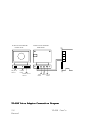
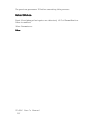
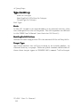
UTY894.EXE
UTY894.EXE is a utility program used for recording and playback
of system messages. Before using the program, you must properly
connect the voice adaptor according to the VP-894 Voice Adaptor
Connection Diagram. Note that the selection button on the voice
adaptor must be set properly to reflect the current operation.
Otherwise it will not work.
There are two menus in UTY894.EXE: the Play Menu and the
Record Menu. When the program is first started, it will try to find
a file named "TEMP.VOC". If the file doesn't exist in the current
directory or if its length is 0, the program will enter the Record Menu
VP-894 User's Manual
57
VP-894 VOICE ADAPTER
FRONT VIEW
VP-894 VOICE ADAPTER
REAR VIEW
3
2
1
0
REC/PLAY
SELECT
POWER
LIGHT
POWER & VOL
SELECT
MIC
TAPE INPUT DC 9V
INPUT
INPUT
VP-894 Voice Adaptor Connection Diagram
58
Manual
VP-894 User's
and create the "TEMP.VOC" file if it is missing. Otherwise it will
enter the Play Menu.
System Hot Keys
Ctrl-P: Enter the Play Menu. If current file length is 0 then an error
message will appear, requesting that some recording be done first.
Ctrl-R: Enter the Record Menu in Append Mode.
Ctrl-S: Save the current recording to a file. If executed from the Play
Menu, only the portion within the Start Position and End Position
will be saved.
Ctrl-O: Open a new voice file. If the file length is 0, enter the Record
Menu, otherwise enter the Play Menu.
Alt-X: Quit.
[F1]: Toggle between the Append Mode and the Overwrite Mode
in the Record Menu. No use in the Play Menu.
Record Menu
(1) Channel Number
Select the channel to operate.
(2) File Name
Same purpose at Ctrl-O. Enter the proper file name.
(3) Record Gain
Sets input signal gain. Use the left/right arrow keys to change the
gain in a -10 to +10 range. The Record Gain may affect the voice
quality, especially when silence compression is enabled. Try recording at different gain levels and hear the difference.
(4) Record Mode
VP-894 User's Manual
59
Select a data rate with the left/right arrow keys. Note that 4.9K and
9.8K are 8K and 16K with silence compression enabled.
(5) Off Threshold
Defines the threshold level for silence. Use the left/right arrow keys
to select a level between 0 and 15. This is useful only when silence
compression is enabled. The Off Threshold will affect the voice
quality, so play with it and use the best level for you.
Play Menu
(1) Channel Number
Select the channel to operate.
(2) File Name
Same purpose at Ctrl-O. Enter the proper file name.
(3) Play Gain
Sets output signal gain. Use the left/right arrow keys to change the
gain in a -10 to +10 range.
(4) Play Mode
Select a playback rate with the left/right arrow keys. Note that voice
quality may be lowered if echo cancellation is enabled.
(5) Increment
Sets the step size for Start/End Positions. Use the left/right arrow
keys to change in a 50 to 10000 (bytes) range.
(6) Start Position
Sets the Start Position for playback. It may be changed in the
following ways:
Left/Right Arrow Keys: step up/down from current position
+ & - Keys: increment/decrement 1 byte
60
Manual
VP-894 User's
Home Key: go to the beginning of file
User may also enter the position directly with digit keys.
(7) End Position
Sets the End Position for playback. It may be changed in the
following ways:
Left/Right Arrow Keys: step up/down from current position
+ & - Keys: increment/decrement 1 byte
End Key: go to the end of file
User may also enter the position directly with digit keys.
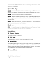
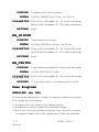
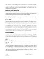
DTMF
.EXE
DTMF.EXE
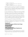
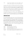
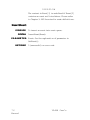
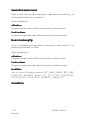
This program shows how to dial and read DTMF tones, and can be
used as a test program for those functions. First the even-numbered
channel will dial a number of digits to the odd-numbered channel,
andthelatterwilldialbacka"*"ifitreceivedthedigitswithnoerror.
Then the process will repeat once with the odd-numbered channel
dialing the even-numbered channel. If any error should happen, the
program terminates immediately with a diagnostic message displayed on the screen. The two channels under test must be connected
together with a regular telephone cord.
3
2
1
0
VP-894SMD
REV. A
VP-894 User's Manual
61
LED3
LED2
LED1
LED0
Figure 6: Interconnection Diagram for "DTMF.EXE".
TEST
.EXE
TEST.EXE
This program shows how to record, play and stop on multiple
channels. Before running this program, please connect the Tester
Box to the VP-894 as in the VP-894 Voice Adaptor Connection
Diagram on page 58. You may use either the Mic. or the TAPE input
to record messages. You must record a message on each channel
before testing the non-stop repeating playback function.
ENERG
Y.EXE
ENERGY
This program shows how to use (function) GetEnergy to monitor
energy level on the line. Application program can use the energy
report to monitor the calling progress. A example of the report file
generated by this program is listed in Appendix A. To run this
program, enter
ENERGY phone_number (> report file)
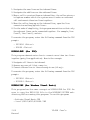
DEMO
.EXE
O.EXE
This program tests the DTMF reception and line recording/playback
functions of the VP-894. You need to connect a phone line to the
channel under test. Make sure the file "GREET.VOC" (which is the
system prompt message) exists in the current directory before
running this program.
When the program is first executed, the system is in the standby mode
and ready to receive phone calls. You should call into the system
from another phone line. The system will answer your call automatically and prompt you to either enter a string of digits (up to 10 digits
before the system times out) or press the "*" key to record a message
up to 30 seconds long. You may press any key to stop recording
62
Manual
VP-894 User's
earlier. After the recording is done, the system will play back the
recorded message once automatically.
OHDETECT
.EXE
OHDETECT.EXE
This program may be used to experiment with Remote Hangup
Detection. To run this program, enter the following command at the
DOS prompt:
OHDETECT /me | /moh[b|r] [options...] [voice_file]
/me Display line energy values on the screen in real time.
/moh
Detect remote hangup based on
b
busy signal feedback.
r
roaring sound feedback.
The following are options:
/pg=?
Set the play gain (-10 to 10).
/rg=?
Set the record gain (-10 to 10).
voice_file Specify the filename to play after the line is connected.
If the remote hangup detection results are not accurate, you may want
to refer to the comments in OHDETECT.C and modify the source
code to get better results.
C ALLOUT
.EXE
ALLOUT.EXE
This program demonstrates CPM functions. To run this program,
enter the following at DOS prompt:
CALLOUT [options...] phone_num [count]
phone_num specify the phone number to call
The following are options:
/n
Specify which line to use, default is line 1 on the board.
For example, /4 tells the program to use line 4.
/rg=?
Set the record gain (-10 to 10).
/area=?
Set the long-distance area code.
/me Display line energy values on screen in real time.
VP-894 User's Manual
63
count
If specified, VP-894 will call "count" number of consecutive phone numbers starting from phone_num.
If there are more than one VP-894 board installed in the system,
CALLOUT will always use the board with the smallest board
number. Only one line will be making phone calls (specified with the
/n option), and other lines will be playing "TEMP.VOC" (must be
present in the current directory) to simulate a heavy workload
situation. Also, if a remote answer is detected, you must type any key
on the keyboard to continue on dialing the next number.
If the CPM results are not accurate, refer to Appendix A: CPM
Principles and experiment with different CPM Parameters in
CALLOUT.C. Also, the program defaults to LineToPBX=TRUE,
you must change it if you are not making outside calls from a PBX.
INTRLINK.EXE
This program demonstrates how to use the SetInterLink()
function. To test this program, call into any interlinked channel
in the system and enter a third party number. The system will
then use the other interlinked channel to call the third party.
When the third party answers the call, you can talk directly to
the third party. Before running this program, make sure the
following files exist in the current directory: WAIT.VOC,
QTELNUM.VOC and FAIL.VOC. To run this program, enter
INTRLINK [options]
/pg=?
/rg=?
/ot=?
/busy=?
/roar=?
64
Manual
Set the play gain (-10 to 10).
Set the record gain (-10 to 10).
Set the off threshold (0 to 15).
Set the remote hung-up busy threshold (0 to 21).
Set the remote hung-up roar threshold (0 to 21).
VP-894 User's
/pbx
/me
Specify that the VP-894 is connected to a PBX.
Specify that the monitor energy is TRUE.
Questions & Answ
er
s
Answe
rs
(1) After installing the VP-894, the system can't start up and the
screen display garbage.
This might be caused by memory location conflict. Set the 32K
shared memory to a different address and try again. If you are
installing quite a few VP-894s into the same computer, make sure the
computer's power supply has enough current output.
(2) After installing VP-894, the screen becomes unstable and
flickersalot.
Your computer's power supply may not have enough current output.
Try taking out a few VP-894 boards and try again.
(3) When installing DRV894.EXE, it reports that it can't find
any boards.
This might be caused by memory location conflict. Please set the 32K
shared memory to a different location and try again. If there is no
memory location conflict for sure, check to see if there is a memory
manager (e.g. 386MAX) or EMS emulator software (e.g. EMM386)
installed in the system. The former re-maps extended memory into
between 640K to 1024K to increase usable DOS memory. The latter
emulates expanded memory from extended memory and uses 64K
memory at A000 - EFFF for page frame. If the system have these
software installed, find out what memory locations are available and
move VP894's 32K shared memory to a non-conflicting location.
(4) When installing DRV894.EXE, it finds only some boards.
VP-894 User's Manual
65
Double check and make sure all boards use the same IRQ and their
shared memory set to the same location.
(5) When installing DRV894.EXE, it reports that it can't find
any IRQ.
This might be caused by IRQ conflict with another add-on card. Also
make sure that all boards use the same IRQ, and only one of them
have DIP switch S1-1 set to ON.
(6) Pulse detection is not very accurate.
Accuracy of pulse detection depends on a lot of factors such as the
line condition, the dialing telephone set quality and the background
noise level. Follow these rules to get better pulse detection results:
A. Don't do pulse detection for long distance calls.
B. Connect VP-894 directly to CO lines instead of going through
a phone system.
66
Manual
VP-894 User's
C. Avoid noisy environment (on the caller side).
D. Avoid using hands-free telephone set (on the caller side).
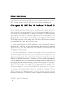
Chapter 5: Clipper API
Ov
vie
w
ve
rv
ew
er
This section presents general information about the VP894 Clipper
API. Because most definitions about this API are the same as the C
API, here we only explain the difference between them. Please refer
to the Chapter on the C API for more information if necessary.
The following files are included in the Clipper API:
.\api894.ch
.\api894.lib
.\demo.rmk
.\src\test.prg
.\src\energy.prg
.\src\callout.prg
.\src\beeper.prg
.\src\dtmf.prg
.\src\ohdetect.prg
.\src\demo.prg
.\src\depulse.prg
.\src\hookstat.prg
.\src\utility.prg
.\bin\demo.exe
.\bin\test.exe
.\bin\dtmf.exe
.\bin\energy.exe
.\bin\hookstat.exe
includefile
library
make file for demo programs
VP-894 User's Manual
67
.\bin\callout.exe
.\bin\beeper.exe
.\bin\ohdetect.exe
.\bin\depulse.exe
The api894.ch is an include file which defines common constants
used in the VP894 API and useful pseudo-function (or called Macro
by others), you must include it on the beginning of each component
file which will refer to them. The \clipper\src subdirectory contains
several example programs to illustrate the VP894 API function
usage.Youcanlaunchtheirexecutablesdirectlyfrom\clipper\bintosee
how they work or use demo.rmk to rebuild them. Before you rebuild
these demo programs, be sure that api894.ch, api894.lib and demo.rmk
are put in same directory with them. On the DOS command line, you
can use the following formula to make all:
rmake demo /F [DEBUG="T"]
RMAKE is a program maintenance utility which comes with the
Clipper compiler. For more information about this utility and it's
options, please refer to the Clipper programmer's guide. If you want
the symbolic information embedded in the built demo programs that
you can use Clipper Debugger - CLD to trace the execution of
program, specifies DEBUG="T" on the trail of RMAKE command.
In the following description, we will briefly explain what makes those
difference between C and Clipper API. There are two main reasons to
cause those differences: (1) data type representation for variable in
memory, (2) the behavior for runtime memory management.
(1) In Clipper, there is no equivalent variable declaration statement
like C's 'struct' which can be used to compose relative members in
sequential memory, so we use array instead in place where API's
function parameter is passed with struct reference data type in C.
(2) There is a built-in Virtual Memory Manager behind each
application which is compiled with Clipper. It gives application
much more memory by using a similar methodology like memory
68
Manual
VP-894 User's
management in some multi-tasking operation system. For efficient
utilizing the limited amount of real memory, most memory object
which are created in runtime would not be fixed at same address
throughout the lifetime of application. These memory object include
variables and array declared 'PUBLIC', 'PRIVATE', 'LOCAL' and
etc. VMM will move them to collect the fragmented free memory
between allocated memory, or swaps the least recently used memory
to disk if necessary.
In the VP894 API, some event-driven function expect parameter
passed with reference to string, we can't just use the reference to
finish the task of called function like in C (remember that eventdriven function operation is still progressing after execution return
back to the calling routine), because the reference will not be valid
after returning back to Clipper. However, there is a Fixed Memory
Allocator in Clipper which can help us to solve this problem. But it
causes additional burden to application to pay attention on deallocating these fixed memory, see function GetDTMF() and
ReadReceiveDTMF() explanation for details.
The API Return Code
There
is
only
a
new
return
code
ERR894_NO_FIXED_HEAP_AVAIL included in VP894's Clipper API:
ERR894_NO_FIXED_HEAP_AVAIL
The virtual memory manager in Clipper finds no available memory
in fixed heap that can be allocated.
VP-894 User's Manual
69
For the other API return codes, please refer to the C API.
The API Functions
GetCtr
lP
aram
GetCtrl
Param
PURPOSE
To get the control parameters for a channel.
SYNTAX GetCtrlParam(ChNum, VP894CPB)
P A R A M E T E R ChNum: The channel number.
VP894CPB: An array of 21 elements used to store
the control parameters returned by the API. In C,
thisparameterisapre-defined'struct'datatypetypeCPB. Almost every element in VP894CPB
has a corresponding member in typeCPB except
the first one. Below is the mapping between them:
VP894CPB[2]
VP894CPB[3]
VP894CPB[4]
VP894CPB[5]
VP894CPB[6]
VP894CPB[7]
VP894CPB[8]
VP894CPB[9]
VP894CPB[10]
VP894CPB[11]
VP894CPB[12]
VP894CPB[13]
VP894CPB[14]
VP894CPB[15]
VP894CPB[16]
VP894CPB[17]
VP894CPB[18]
VP894CPB[19]
VP894CPB[20]
70
Manual
OffHookDelay
OnHookDelay
FlashTime
PulseMake
PulseBreak
PulsePostDigitPause
ToneDuration
InterTonePause
OutsideLineAccess
RingsToAnswer
WaitAnswerDuration
InterDigitPause
NoSignalTimeOut
MaxSilence (obsolete)
MaxRoarDuration (obsolete)
PlayGain
RecordGain
PlayMode
RecordMode
VP-894 User's
VP894CPB[21] OffThreshold
VP894CPB[1] is a composition of the following:
DialMode (CPF_DIAL_PULSE)
LineToPBX (CPF_LINE_TO_PBX)
TriggerMode (CPF_MONITOR_LOCAL_PHONE_STATUS)
DetectRoaringRemoteHangUp (CPF_DETECT_HOWL_RHU)
DetectBusyRemoteHangUp (CPF_DETECT_BUSY_RHU)
DetectRemoteHangUpWhenRecording
(CPF_DETECT_RHU_WHEN_RECORDING)
DetectRemoteHangUpAlways (CPF_DETECT_RHU_ALWAYS)
StopOperationRemoteHangUp (CPF_STOP_OPERATION_RHU)
MonitorDTMF (CPF_MONITOR_DTMF)
MonitorEnergy (CPF_MONITOR_ENERGY)
DetectVoltReverseRemoteHangUp
(CPF_DETECT_VOLT_REVERSE_RHU)
DetectSilentWhenRecording
(CPF_DETECT_SILENT_WHEN_RECORDING)
LearnPulse (CPF_LEARN_PULSE)
MonitorPulse (CPF_MONITOR_PULSE)
These are 'bit field' declarators of structure
typeCPB in C. In contrast, there is no similar data
type representation in Clipper, so we define a
group of corresponding constants in the include
file API894.CH. The corresponding Clipper
constants are shown in the parenthesizes.
You can combine these constants which control
certain operation of the VP894 with operator '+'
and then assign the result value to VP894CPB[1].
For definitions of these parameters, please refer
to Chapter3: API in General for more details.
VP-894 User's Manual
71
RETURNS 0 (successful) or error code
EVENT TYPE None
SetCtr
aram
SetCtrl
Param
lP
PURPOSE
To set the control parameters for a channel.
SYNTAX SetCtrlParam(ChNum, VP894CPB)
P A R A M E T E R ChNum: The channel number.
VP894CPB: See the parameter explanation of
GetCtrlParam().
72
Manual
VP-894 User's
RETURNS 0 (successful) or error code
EVENT TYPE EVT_EOP_NORMAL
GetDTMF
PURPOSE
To get a string of DTMF inputs from a channel.
SYNTAX GetDTMF(ChNum, Count, AcceptDTMF,
ExitDTMF)
P A R A M E T E R ChNum: The channel number.
Count: The number of DTMF to receive.
AcceptDTMF: Which DTMF tones are acceptable.
ExitDTMF: Which DTMF tones can be used to
terminate input before Count number of DTMF
tones are received.
RETURNS 0 (successful) or error code
EVENT TYPE E V T _ E O P _ N O R M A L ,
EVT_DTMF_INTERCEPT,
EVT_TIME_OUT.
C O M M E N T If GetDTMF() returns zero to indicate success, the
API will internally maintain a buffer, which has
Count+1 bytes, allocated through Fixed Memory
Allocator in Clipper to store the received DTMF.
Application can retrieve these DTMF by invoking
function GetReceivedDTMF() when one of the
relevant events arrives. GetReceivedDTMF() will
free the previous allocated buffer after it copies
received DTMF into the referenced variable passed
by the application. The application must invoke
GetReceivedDTMF() after calling GetDTMF(),
even if event EVT_TIME_OUT is received. The
VP-894 User's Manual
73
purpose is to free the buffer. The only exception
is if you call StopCh() after GetDTMF() is called,
there is no need to call GetReceivedDTMF().
ReadReceiv
edDTMF
ReadReceivedDTMF
PURPOSE
To retrieve the received DTMF on a channel.
SYNTAX ReadReceivedDTMF(ChNum, Buffer)
P A R A M E T E R ChNum: The channel number.
Buffer: A referenced variable to store the DTMF.
RETURNS 0 (successful) or error code
EVENT TYPE None.
C O M M E N T After invoking this function, the buffer will not be
valid until the next GetDTMF() event arrives.
74
Manual
VP-894 User's
When the buffer is invalid, calling this function
will result in a ERR894_INVALID_CHANNEL
error to indicate that the buffer is not valid.
GetEv
ent
GetEvent
PURPOSE
To retrieve the next event information in queue.
SYNTAX GetEvent(Event)
P A R A M E T E R Event: An array of 3 elements used to store event
information:
Event[1] = channel number sending the event.
Event[2] = event type.
Event[3] = additional data.
RETURNS 0 if event queue is empty,
non-zero if successful.
EVENT TYPE None.
COMMENT
The meaning of Event[3] depends on the event
type returned in Event[2]:
Event [2]
Event[3]
-------------------------------------------------------------------------------EVT_DTMF_INTERCEPT orDTMF digit in ASCII code
EVT_DETECT_DTMF
---------------------------------------------------------------------------------------EVT_DETECT_PULSE
pulse digit in ASCII code
-------------------------------------------------------------------------------EVT_PCMIO_ERROR
error code from DOS
-------------------------------------------------------------------------------EVT_INTRN_QUEUE_
ERR894_EVENT_QUEUE_
OVERFLOW
OVERFLOW or
ERR894_PCMIO_QUEUE_
VP-894 User's Manual
75
OVERFLOW
The content in Event[3] is undefined if Event[2]
contains an event not listed above. Please refer
to Chapter 3: API Overview for event definitions.
Inser
tEv
ent
Insert
vent
PURPOSE
To insert an event into event queue.
SYNTAX InsertEvent(Event)
P A R A M E T E R Event: See the explanation of parameter in
GetEvent().
RETURNS 0 (successful) or error code
76
Manual
VP-894 User's
EVENT TYPE None
C O M M E N T Event type from numeric 160 to 255 are reserved
for the application for customized use.
GetCPMP
aram
GetCPMParam
PURPOSE
To get Call Progress Monitor (CPM) parameters.
SYNTAX GetCPMParam(CPMParam)
P A R A M E T E R CPMParam: An array used to store the CPM
parameters. Please refer to Appendix A: CPM
Principles for more information. To represent the
'struct' in C, we use an array in Clipper. Every 27
consecutive elements in this array are grouped to
specify a signal type's characteristic. You can only
characterize a signal with up to 6 different duty
cycles. Since there are 13 different signal types
must be defined, this array has 351 elements. The
following table lists definition of each element:
Central Office
CPMParam[1] - [27]
CPMParam[28] - [54]
CPMParam[55] - [81]
CPMParam[82] - [108]
CPMParam[109] - [135]
CPMParam[136] - [162]
ring tone
busy tone
invalid number
dialtone
1st user-defined tone
2nd user-defined tone
Private Phone System
CPMParam[163] - [189]
CPMParam[190] - [216]
CPMParam[217] - [243]
CPMParam[244] - [270]
CPMParam[271] - [297]
CPMParam[298] - [324]
ring tone
busy tone
invalid number
dialtone
1st user-defined tone
2nd user-defined tone
VP-894 User's Manual
77
Beeper
CPMParam[325] - [351] beeper acknowledge tone
For the 27 elements in each group:
CPMParam[n+0] Wave Count
CPMParam[n+1] Type
CPMParam[n+2] Recognize Cycle(s)
CPMParam[n+3] Wave[0] Silence
CPMParam[n+4] Wave[0] None Silence
CPMParam[n+5] Wave[0] Silence Tolerance
CPMParam[n+6] Wave[0] None Silence Tolerance
CPMParam[n+7] Wave[1] Silence
CPMParam[n+8] Wave[1] None Silence
CPMParam[n+9] Wave[1] Silence Tolerance
CPMParam[n+10] Wave[1] None Silence Tolerance
......
CPMParam[n+23] Wave[5] Silence
CPMParam[n+24] Wave[5] None Silence
CPMParam[n+25] Wave[5] Silence Tolerance
78
Manual
VP-894 User's
CPMParam[n+26] Wave[5] None Silence Tolerance
RETURNS 0 (successful) or error code
EVENT TYPE None.
SetCPMP
aram
SetCPMParam
PURPOSE
To set CPM parameters.
SYNTAX SetCPMParam(CPMParam)
P A R A M E T E R CPMParam: See the explanation of parameter in
VP-894 User's Manual
79
GetCPMParam().
RETURNS 0 (successful) or error code
EVENT TYPE None.
GetHungUpP
aram
GetHungUpParam
PURPOSE
To get current Hung-Up parameters.
SYNTAX GetHungUpParam(HungUpParam)
P A R A M E T E R HungUpParam: An array with 27 elements used to
store Hung-Up parameters. The Hung-Up parameters specify the characteristics of disconnect
signal on the telephone line after the caller hangs
up. In C, this parameter is a reference to a 'struct'
data type - typeHungUpParam. There is a one to
one mapping for the HungUpParam array:
HungUpParam[1]
HungUpParam[2]
HungUpParam[3]
HungUpParam[4]
HungUpParam[5]
HungUpParam[6]
HungUpParam[7]
HungUpParam[8]
HungUpParam[9]
HungUpParam[10]
HungUpParam[11]
..........
HungUpParam[24]
HungUpParam[25]
HungUpParam[26]
HungUpParam[27]
MinBusyDuration
MinRoarDuration
BusyThreshold
RoarThreshold
MinSilentDuration
SilentThreshold
Busy.Varieties
Busy.Cadence[0].Silence
Busy.Cadence[0].NoneSilence
Busy.Cadence[0].SilenceTolerance
Busy.Cadence[0].NoneSilenceTolerance
Busy.Cadence[4].Silence
Busy.Cadence[4].NoneSilence
Busy.Cadence[4].SilenceTolerance
Busy.Cadence[4].NoneSilenceTolerance
For a full description about each parameter,
80
Manual
VP-894 User's
please refer to Chapter 3: API Overview.
RETURNS 0 (successful) or error code
EVENT TYPE None.
SetHungUpP
aram
SetHungUpParam
PURPOSE
To set Hung-Up parameters.
SYNTAX SetHungUpParam(HungUpParam)
P A R A M E T E R HungUpParam: See the explanation of parameter
VP-894 User's Manual
81
in GetHungUpParam().
RETURNS 0 (successful) or error code
EVENT TYPE None.
SetInterLink
PURPOSE
To connect or disconnect the interlink between
two adjacent channels.
SYNTAX SetInterLink(ChNum, Connect)
P A R A M E T E R ChNum: The channel number.
Connect: A Boolean value:
.T. = connect
.F. = disconnect
RETURNS 0 (successful) or error code
EVENT TYPE EVT_EOP_NORMAL
C O M M E N T When two channels are interlinked, you can
record sound or monitor energy (CPM) only on
the even channel.
82
Manual
VP-894 User's
Other Functions
Any function not described above has the same syntax as in the C
API. Please refer to the C API section for more information.
Cha
pter 6: API For W indo
ws V isual C
Chap
indows
Microsoft Windows provides a multi-tasking environment which is
very suitable for running multi-line voice processing applications.
Therefore the Windows API is made available to VP894 system
developers who want to develop applications for Windows. The
Windows API allows up to 16 windows to be opened and running
VP894 applications at the same time. The major differences between
the Windows API and the DOS API are:
1. Functions GetEvent() and FlushEvent() are eliminated from the
Windows API. Instead, we use each Windows application's message
queue directly for the communication between the Windows API and
the application program.
2. For the Windows API, function Init894() will now return an
"instance number" which serves as an identification number for the
application program. Note that this "instance number" is not the
same as a "Windows instance". Instead, it is an internal parameter
for the Windows API to distinguish the many possible application
programs running simultaneously. When calling most of the Windows API functions, the application program must supply this
"instance number" so that the Windows API knows who is calling.
3. Because the Windows API itself is a dynamic linking library
(DLL) instead of a Windows task, it has no direct access to most
Windows resources. Therefore it must request Windows resources
VP-894 User's Manual
83
via the calling programs. Since only one application instance is
required to maintain these Windows resources for the Windows API,
usually it is the first one which calls the Windows API.
Butifthis"firstinstance"terminates(bycallingfunctionClose894())
before other instances do, the Windows API will send an
EVT_SET_CONTROL event to all other instances and hopefully
someone will call function AcceptControl() to take over the resource
maintenance job. Therefore the application program must pay close
attention to the EVT_SET_CONTROL event and take proper action,
or the system will no longer work.
After installing the Windows API, you should find a "VP894.DLL"
file in your Windows directory. To use it, all you need to do is to
link the application program with the VP894.LIB import library.
Comparison with the DOS API
The Windows API is mostly the same as the DOS API, except for
the following:
Event Type Definitions
There are only three new event types in addition to the DOS API.
They are:
1. EVT_SET_CONTROL
As explained earlier in the Introduction section, this event is posted
when the resource-handling application instance terminates (by
calling Close894()). When this event is posted, one of the instances
must call function AcceptControl() to take over resource-handling
chores, or the system will stop working.
2. EVT_REQUEST_ADAPTER
When an application program needs more VP894 resources, it may
issue this event to other application programs. If other programs can
release some VP894 resources, they may call function
ReleaseAdapter() to do so.
84
Manual
VP-894 User's
3. EVT_FREE_ADAPTER
Whan an application program receives this event, it means that some
other programs have released some VP894 resources. These released resources may be claimed by calling function AddAdapter().
When an application program terminates, it must call function
Close894() to release its resources and etc. Therefore it is not
necessary for the terminating program to call function
ReleaseAdapter() before calling function Close894().
For the above three events, there is no definition for the Issuer. As
for the Event Data, it is the corresponding board number for events
EVT_REQUEST_ADAPTER and EVT_FREE_ADAPTER, and
no definition for event EVT_SET_CONTROL.
Error Code Definitions
These are the error codes for the Windows API in addition to the ones
defined in the DOS API:
1. ERR894_INSTALL_NONE
Can not find the VP894.DLL.
2. ERR894_IRQ_NOT_FOUND
Can not find VP894's IRQ setting.
3. INCOMPATILBE_FIRMWARE
The firmware version on VP894 is not compatible with the API.
4. ERR894_WINDOWS_ERROR_ALLOC_SELECTOR
Can not allocate free selector from Windows.
5. ERR894_WINDOWS_ERROR_SET_SELECTOR
Can not set the selector base.
6. ERR894_NO_MORE_ADAPTER
There are no more resources available.
7. ERR894_BAD_WINDOWS_HANDLE
The Windows handle (passed to the 894Win API from the application
program) is invalid.
8. ERR894_REGISTER_MESSAGE
VP-894 User's Manual
85
Can not register VP894 message to Windows.
9. ERR894_SET_TIMER
Can not install system timer.
10. ERR894_BAD_FILE_NAME
The specified voice file does not exist.
11. ERR894_RECORD_FILE
The specified voice file can not be created.
12. ERR894_NO_MORE_INSTANCE
Can not set up any more VP894 instances.
13. ERR894_INVALID_OWNER
The API-calling program does not own the specified channel.
14. ERR894_INVALID_HANDLE
The VP894 instance number is invalid.
15. ERR894_UNKNOWN_ERROR
There is an unknown error.
Event Passing
The VP894 events are passed through the application program's
message queue. To receive VP894 message, the application program
should first call function Query894() to obtain the message's
identifier. The message retrieved from the message queue contains
the event type in a "word" parameter, and the event data location in
a "double word" parameter. The event data is of the typeEvent
structure, as defined in API894.H. Since the message queue has a
capacity of only 8 messages for each Windows application, it is quite
possible that the message queue may overflow in a multi-line
application. Therefore SetMessageQueue() should be called to
increase the message queue size before creating any windows.
API Functions
Most of the functions in the DOS API are supported and are not
repeated below. Please refer to the DOS API section for descrip-
86
Manual
VP-894 User's
tions. However, you must add the instance identifier as the first
parameter to these functions.
Init894
PURPOSE To initialize the instance and allocate necessary
resources.
SYNTAX Init894(HWND hWnd, LPINT Instance, LPINT
ownerAdapter, DWORD owner)
P A R A M E T E R hWnd: The Windows handle.
Instance: An integer pointer for storing the
instance identifier returned from the API.
ownerAdapter: Pointer to a 16-element integer
array with VP894 allocation information. A nonzero value in an element means that the corresponding board has been allocated for this application to use. For example, if ownerAdapter[1],
ownerAdapter[5] and ownerAdapter[10] all have
non-zero values, then the application program
owns board #1, #5 and #10.
owner: The requested board numbers to be allocated. In API894.H there are definitions for
constants OWNER_0~OWNER_31 and
OWNER_
ALL, each representing a corresponding board
number. Currently only OWNER_0~OWNER_15
and OWNER_ALL are valid. These constants
may be bit-wise ORed to request multiple boards.
Note that OWNER_ALL can be used to request
all free boards in the system.
VP-894 User's Manual
87
RETURNS 0 (successful) or error code
EVENT TYPE
None.
Close894
PURPOSE To release all allocated resources back to the pool
and do necessary house-keeping work before
program termination.
SYNTAX Close894(int inst)
P A R A M E T E R Inst: The instance identifier (obtained from
callingfunctionInit894()).
88
Manual
VP-894 User's
RETURNS 0 (successful) or error code
EVENT TYPE
None.
OpenV
oice
OpenVo
iceFile
PURPOSE To open a voice file.
SYNTAX OpenVoiceFile(LPSTR filename, long startpos,
UINT fuMode)
P A R A M E T E R filename: The filename to open.
startpos: After the file is opened, move the file
pointer to this position.
fuMode: The file open mode. This parameter is
exactly the same as the third parameter in
OpenFile() which is a Windows API function.
Please refer to the Windows SDK manuals for
more information.
VP-894 User's Manual
89
RETURNS Same as returned from OpenFile().
EVENT TYPE
None.
CloseV
oiceFile
CloseVoiceFile
PURPOSE To close a file.
SYNTAX CloseVoiceFile(int inst, int ChNum)
P A R A M E T E R inst:Theinstanceidentifier.
ChNum: The relevant channel number.
90
Manual
VP-894 User's
RETURNS 0 (successful) or error code
EVENT TYPE
None.
AcceptContr
ol
AcceptContro
PURPOSE To accept the resource management job relinquished from a terminating instance.
SYNTAX AcceptControl(int inst)
P A R A M E T E R inst:Theinstance identifier.
RETURNS 0 (successful), otherwise the resource management job has been taken over by another instance.
The returned value is really not important as long
as some other instance takes over the resource
management job. But the application program
must call this function when it receives the
VP-894 User's Manual
91
EVT_SET_CONTROL event.
EVENT TYPE
None.
Query894
PURPOSE To obtain information on the VP894 resources.
SYNTAX Query894(LPINFO894 lpInfo, LPINT Installed)
P A R A M E T E R lpInfo: lpInfo contains the information returned
from the function. It is a pointer pointing to data
structure INFO894, defined in API894.H as :
verMajor: VP894.DLL's major version number
verMinor: VP894.DLL's minor version number
Msg: VP894's registered message ID under
Windows. By checking the message ID, the
application program knows whether the message comes from the VP894 or not.
IRQ: VP894's IRQ setting.
SRAM: Location of VP894's shared buffer.
Installed: Pointer to a 16-element integer array
with VP894 allocation information. A non-zero
value in an element means that the corresponding
board has been installed in the system. For
example, if Installed[1], Installed[5] and
Installed[10] all have non-zero values, it means
92
Manual
VP-894 User's
board #1, #5 and #10 are found.
RETURNS None.
EVENT TYPE
None.
RequestAda
pter
RequestAdap
PURPOSE To request more VP894 resources. When this
function is called, VP894.DLL will send event
EVT_REQUEST_ADAPTER to the application(s)
owning the requested resources. It will then
inform the caller about the available resources by
sending event EVT_FREE_ADAPTER to the
caller. However, no resources will be allocated to
the caller until function AddAdapter() is called.
SYNTAX RequestAdapter(int inst, DWORD owner)
P A R A M E T E R inst:Theinstanceidentifier.
owner: The VP894 resources requested. Definition is the same as the parameter "owner" in
VP-894 User's Manual
93
Init894().
RETURNS 0 (successful) or error code.
EVENT TYPE
None.
ReleaseAda
pter
ReleaseAdap
PURPOSE To release some VP894 resources.
SYNTAX ReleaseAdapter(int inst, DWORD owner)
P A R A M E T E R inst:Theinstanceidentifier.
owner: The VP894 resources to be released.
Definition is the same as the parameter "owner"
inInit894().
94
Manual
VP-894 User's
RETURNS 0 (successful) or error code
EVENT TYPE
None.
GetFr
eeAda
pter
GetFreeAda
eeAdap
PURPOSE To learn what VP894 resources are available.
SYNTAX GetFreeAdapter(LPINT freeAdapter)
P A R A M E T E R freeAdapter: Pointer to a 16-element integer array
with VP894 allocation information. A non-zero
value in an element means that the corresponding
board is available. For example, if freeAdapter[1],
freeAdapter[5] and freeAdapter[10] all have nonzero values, then it means board #1, #5 and #10
arefree.
RETURNS A DWORD which has the same definition as the
"owner" parameter in function Init894(). This
DWORD can be used directly as the 2nd parameter to call function RequestAdapter() or
VP-894 User's Manual
95
function AddAdpter().
EVENT TYPE
None.
AddAda
pter
AddAdap
PURPOSE To allocate more VP894 resources. The desired
resources should be either free or requested
from another application by calling function
RequestAdapter() first.
SYNTAX AddAdapter(int inst, DWORD owner)
P A R A M E T E R inst:Theinstanceidentifier.
owner: The resources to be allocated. It has the
same definition as the "owner" in function
RequestAdapter(), but requested resources (board
numbers) must be available. To learn whether a
certain instance has successfully obtained
requested resources, you may call function
Get894Owner().
96
Manual
VP-894 User's
RETURNS 0 (successful) or error code.
EVENT TYPE
None.
GetIncompatible
PURPOSE Check to see if there are, in the system, any
VP894 boards equipped with incompatible
firmware version.
SYNTAX GetIncompatible(LPSTR incompatible)
P A R A M E T E R incompatible: Pointer to a 16-element character
array with firmware compatibility information. A
non-zero value in an element means that the
corresponding board has incompatible firmware.
For example, if incompatible[1], incompatible[5]
and incompatible[10] all have non-zero values,
then VP894 board #1, #5 and #10 all have
incompatible firmware versions.
RETURNS 0 = there are no incompatible firmware versions,
non-zero = there are some incompatible
VP-894 User's Manual
97
firmware versions.
EVENT TYPE
None.
Get894V
er
sion
Get894Ve
rsion
PURPOSE To obtain the firmware version of a VP894 board.
SYNTAX Get894Version(int AdptrNum)
P A R A M E T E R AdptrNum: The VP894's board number.
RETURNS An integer, with the major version number in the
high byte and the minor version number in the
98
Manual
VP-894 User's
low byte.
EVENT TYPE
None.
Valid894Handle
PURPOSE To verify if a certain VP894 instance identifier is
a valid one.
SYNTAX Valid894Handle(int inst)
P A R A M E T E R inst: The instance identifier to be verified.
RETURNS 0 = The instance identifier is invalid,
VP-894 User's Manual
99
Non-zero = The instance identifier is valid.
EVENT TYPE
None.
Test894Owner
PURPOSE To verify whether a certain VP894 instance owns
a certain board number.
SYNTAX Test894Owner(int inst, int AdptrNum)
P A R A M E T E R inst:Theinstanceidentifier.
AdptrNum: The board number to be verified.
RETURNS 0 = The board does not belong to the instance,
100
Manual
VP-894 User's
non-zero = The board belongs to the instance.
EVENT TYPE
None.
Get894Owner
PURPOSE To learn what VP894 resources are owned by a
certaininstance.
SYNTAX Get894Owner(int inst, LPINT installed)
P A R A M E T E R inst:Theinstanceidentifier.
installed: Pointer to a 16-element integer array
with VP894 allocation information. A non-zero
value in an element means that the corresponding
board is owned by the instance. For example, if
Installed[1],Installed[5]andInstalled[10]all
have non-zero values, then the instance owns
board #1, #5 and #10.
RETURNS A DWORD, it has the same definition as the
"owner" parameter in Init894(). If a bit is set to 1,
it means the instance owns the board corresponding to the bit. The bit definitions are found in
VP-894 User's Manual
101
102
Manual
VP-894 User's
API894.H.
EVENT TYPE
None.
Chapter 7: Visual Basic API
This version of VP-894CC.VBX must be run under Windows 3.1 or
Windows 95, and is compatible with Visual Basic version 2.00 and
up. Since VP894CC.VBX is just a "function wrapper" for
VP894.DLL, you must install these two dynamic libraries in your
Windows\System subdirectory.
To use VP894CC custom control, first pull down VB's File Menu
and select "Add File.." Then select "VP894CC.VBX" in the dialog
box. If no error occurs in the above steps, the following icon will
appear in the ToolBox.
This icon represents VP894 custom control.
You will also need to use "Add File.." to add code module
"VP894INC.BAS". In this file, there are definitions of VP894CCrelated global constant, user-defined data type and API function
prototype declaration.
Each VP894 control placed on the form represents a VP894 adapter,
with its status indicated by one of the following two icons.
At design time, it means the adapter is free. At run
time, it means the adapter has been allocated to
the application program.
VP-894 User's Manual
103
At either design time or run time, it means the
adapter does not exist or has been allocated to
another task.
Note that these icons may be turned on or off at run time by setting
the "Visible At Runtime" (an environment property of VP894CC) to
"TRUE" or "FALSE". Please refer to the descriptions on "environment" in later sections for details.
Properties
The following abbreviations represent the accessibility of a property
at design time or run time:
R W
RO
W O
NA
read/write
read only
write only
not available
Status
Design Time: RO
Run Time: RO
"Status" is an integer which indicates the current status of a VP894
control. Its value range is from 0 to 2 with the following definitions:
2: Indicates that the adapter has been allocated to another task,
1: Indicates that the adapter is not installed in the system,
0: At design time, it indicates that the adapter is free; at run time,
itindicatesthattheadapterisallocatedtothiscontrol(thereforeall
its functions are available to this control).
Ada
pterNumber
AdapterNumber
Design Time: RW
Run Time: RO
104
Manual
VP-894 User's
"AdapterNumber" is an integer, its value equals the adapter number
of this control. At run time, a VP894 custom control uses this number
to request an adapter from VP894.DLL.
Ctr
lP
aram
rl
Param
Design Time: RW
Run Time: NA
At design time, if you select the "CtrlParam" property in the
properties box, VP894 custom control will display a dialog box
showing all the default channel control parameters. The channel
control parameters are described in Chapter 3. You may modify
these parameters as desired. These default channel control parameters are used to set the control parameters when a channel is
initialized. If you need to change them at run time, you must use the
"SetCtrlParamProp()" function provided by VP894CC.
Flo
wEditor
owEditor
Design Time: RW
Run Time: NA
"FlowEditor" is the key to editing the VP894CC's telecommunication flow control. At design time, if this property is selected, VP894
custom control will display a dialog box in which you may add, delete
and modify the telecommunication flow control.
In the VP894CC flow control, we use "process" as an execution unit.
There are 14 different "processes": 1. Query, 2. Record, 3. Call, 4.
Stop Channel, 5. Set Control Parameter, 6. Interlink, 7. Flash, 8.
Pick Up, 9. Hang Up, 10. Ringing, 11. Local Phone Picked Up, 12.
Local Phone Hung Up, 13. Remote Hang Up, 14. Learning Pulse
Success. There are different "properties" for different "processes",
but the following properties are common to all processes:
1. ID
The process' ID code.
VP-894 User's Manual
105
2. Type
The process' type.
3. Name
The process' name, which is only used for documentation purpose
by the application programmer. It may contain a string of any ASCII
characters except the null character.
4. Default Next Step
It specifies the ID code of the next process to execute if the current
process is terminated normally. If this property is blank or "-1", it
means the next step is to enter the idle state. However, different types
of process may have different definitions for "normal termination".
Please refer to each process' description.
5. Fire Event
Only the following processes have this property: Ringing, Local
Phone Picked Up, Local Phone Hung Up, Remote Hang Up and
Learning Pulse Success. This property indicates whether to fire a VB
Event to notify the application program when one of above conditions is met. The VB Events are "Ringing", "PhonePickedUp",
"PhoneHungUp", "RemoteHangUp" and "LearnPulseSuccess" respectively.
6. Fire Pre-Execution Event
The following processes do not have this property: Ringing, Local
Phone Picked Up, Local Phone Hung Up, Remote Hang Up and
Pulse Learning Success. This property determines whether to fire a
VB Event - PreExecuted to notify the application program about the
process to be executed.
7. Fire Post-Execution Event
The following processes do not have this property: Ringing, Local
Phone Picked Up, Local Phone Hung Up, Remote Hang Up and
Pulse Learning Success. This property determines whether to fire an
VB Event - PostExecutedxxx (xxx stands for different process types)
106
Manual
VP-894 User's
to notify the application program about the process which has been
executed.
Now we will describe the properties unique to each process:
[1] Query
Query is used to play one or more voice files while receiving touch
tone inputs. If you use the "New" button in the "Flow Editor" to
create this process, the following two dialog boxes will be displayed
on the Windows desktop: "Prompt List" and "Next Step Table".
Prompt List
Used to select the voice files to be played. The order in which the
files are listed in the "Prompt List" will be the order the files are
played. If you want to change the order, simply point the mouse to
the file, press the left button on the mouse and drag the file to the new
position. Note that the voice files are always accessed from the search
path specified in the "Prompt Directory" in the VP894CC property
- Environment. If you need to access voice files from a different
directory or change the "Prompt List" at run time, use function
SetQueryProp().
Next Step Table
Contains the next-step process IDs for different remote touch tone
inputs and the timeout process if no valid inputs are received during
the waiting period for remote inputs.
In addition to the above two properties and the common properties,
Query has the following three properties:
Exit DTMF
Specifies which touch tone key is used to terminate the remote input
before entering enough touch tones. For example, if up to 6 digits
are to be entered, the caller may enter only 3 digits followed by the
"Exit DTMF" key. This will terminate the Query process and move
on to the next step process. Most applications use the "#" and/or "*"
key for this purpose. You may enter the setting directly into the edit
control of "Exit DTMF", or use the phone symbol nearby (the
VP-894 User's Manual
107
pressed-down keys are the settings).
Accepted DTMF
Selects which touch tone keys are acceptable for input. You may
enter the selections directly in the edit control of "Accepted DTMF",
or use the phone symbol nearby (the pressed-down keys are
selected).
DTMF Amount
Sets the maximum number of touch tone keys to receive.
[2] Record
"Record" is used to record a voice file. If you use the "New" button
in "Flow Editor" to create this process, a "Next Step Table" will be
displayed on the Windows desktop. This property has the same
definition as the "Next Step Table" property in "Query". There are
three other properties:
Exit DTMF
Has the same definition as "Exit DTMF" in "Query".
Length
Specifies the maximum recording length.
File Name
Contain the name of the voice file. Note that the voice files are always
accessed from the search path specified in the "Record Directory"
in the VP894CC property - Environment. If you need to access voice
files from a different directory or change the Record properties at run
time, use function SetRecordProp().
[3] Call
"Call" is used to make a phone call to an outside number, an internal
station or a pager. If you use the "New" button in Flow Editor to
create this process, a new dialog box "More Call Properties" will be
displayed. "Call" has the following process-dependent properties:
Called Type
Specifies whether to call an outside number, an internal station or a
108
Manual
VP-894 User's
pager.
Number
Contains the number to call.
Message
Holds the message for calling a pager. The message must contain any
applicable prolog and/or epilog (such as the "#" key), the system will
not insert those keys automatically.
Called Failure Next Step
Specifiesthenext-stepprocessIDifthecallingfails(duetolinebusy,
no answer and etc.).
Don't Execute CPM
Don't Wait Dial Tone
Detect Invalid Number
Detect 1st User-Defined Signal
Detect 2nd User-Defined Signal
These are the calling modes for calling outside numbers or internal
stations. Please refer to the descriptions on function CallLocal(). If
the calling is successful, the subsequent execution flow is determined
by "Default Next Step". If you need to change this process'
properties dynamically during runtime, use function SetCallProp().
[4] Stop Channel
Stops the current process.
[5] Set Control Parameter
This process is used to change certain control parameters at run time.
For descriptions on the process-dependent properties, please refer to
Chapter 3: API Overview.
[6] Interlink
To make/break the telephone link between two coupling channels.
VP-894 User's Manual
109
[7] Flash
To do a hookswitch flash (usually for transferring a call). Flash
duration is determined by "Flash Time".
[8] Pick Up
To pick up the phone.
[9] Hang Up
To hang up the phone.
[10] Ringing
This process is a notification type. When an incoming call is
detected, the VB Event-Ringing will be fired to notify the application
program if process property-Fire Event is set.
[11] Local Phone Picked Up
This process is a notification type. When local phone pickup is
detected, the VB Event-PhonePickedUp will be fired to notify the
application program if process property-Fire Event is set.
[12] Local Phone Hung Up
This process is a notification type. When local phone hangup is
detected, the VB Event-PhoneHungUp will be fired to notify the
application program if process property-Fire Event is set.
[13] Remote Hang Up
This process is a notification type. When remote hangup is detected,
the VB Event-RemoteHangUp will be fired to notify the application
program if process property-Fire Event is set.
[14] Learning Pulse Success
Thisprocessisanotificationtype.Inordertocreatethisprocess,the
110
Manual
VP-894 User's
Learn Pulse parameter (in CtrlParam) must be checked first. After
the pulse learning is completed successfully, the VB EventLearnPulseSuccess will be fired to notify the application program if
process property-Fire Event is set.
En
vir
onment
Env
ronment
Design Time: RW
Run Time: NA
If you selected this property in the properties box, a new dialog box
will pop up and show the environment options, including:
1. Prompt Directory
The default directory where prompt voice files are stored.
2. Record Directory
The default directory where recorded voice files are stored.
3. Auto-Executed Step After Enable
Specifies the process ID which must be executed automatically if
process property-Active is set to TRUE. To change this option at run
time, use property-AutoExecProc.
VP-894 User's Manual
111
4. Visible At Runtime
Indicates whether the VP894 control symbol and status will be
displayed at run time.
Activ
e
Active
Design Time: NA
Run Time: RW
This property consists of a Boolean integer array of 4 elements, each
representing the status of a corresponding channel. When "Active"
112
Manual
VP-894 User's
is set to FALSE, the channel enters the idle state. When "Active" is
changed from FALSE to TRUE, the process ID (if valid) specified
in "AutoExecProc" will be executed automatically.
A utoEx
ecPr
oc
utoExecPr
ecProc
Design Time: NA
Run Time: RW
This property consists of an integer array of 4 elements, each
VP-894 User's Manual
113
contains the process ID (to be executed automatically upon start-up)
of a corresponding channel. Please refer to the descriptions above for
the property-Active.
CPMP
aram
CPMParam
Design Time: RW
Run Time: NA
If you selected this property in the properties box, a dialog box will
pop up and show the default values for CPM parameters. You may
114
Manual
VP-894 User's
modify them as needed. For descriptions on the CPM parameters,
please refer to the C API function GetCPMParam() and Appedix A:
CPM Principles for more details.
HungUpP
aram
HungUpParam
Design Time: RW
Run Time: NA
If you selected this property in the properties box, a dialog box will
pop up and show the default values for the Hungup Detection
VP-894 User's Manual
115
parameters. You may modify them as needed. For descriptions on
the Hungup Detection parameters, please refer to the "HangUp
Parameter Definitions" in Chapter 3: API Overview.
PromptDir
Design Time: NA
Run Time: RO
116
Manual
VP-894 User's
This property consists of a character string storing the search path
for the prompt voice files. It is the same as in the Prompt Directory
of property-Environment.
RecordDir
Design Time: NA
Run Time: RO
VP-894 User's Manual
117
This property consists of a character string storing the search path
for the recorded voice files. It is the same as in the Record Directory
of property-Environment.
Ev
ents
Events
All VP894CC events have two common parameters: ChNum and
idCurProc. ChNum is the "local" channel number firing the event.
The range of ChNum is from 0 to 3, designating the four channels
of a VP894 control. To get the "global" channel number as defined
in VP894 User's Manual, simply multiply the AdapterNumber by 4
and add the ChNum. idCurProc is the current process ID when the
eventisfired.
When you use the Flow Editor to design program flow at design time,
the program flow is "static" and the interactions among processes are
always fixed. If you want to make the program flow "dynamic", i.e.
change the program flow based on some runtime conditions, you may
change the content of idCurProc inside the event procedure. When
the event procedure is finished and program control returns to
VP894CC, the new process (with its ID in idCurProc) will be
executed. The only exceptions are event-DetectDTMF and eventDetectPulse, since in these two event procedures you can not change
the program flow by changing the idCurProc.
There are three factors affecting the VP894CC program flow at
runtime, in the following priority order (first factor has the highest
priority):
1. VP894CC property-Active changed from FALSE to TRUE (see
previous descriptions),
2. idCurProc changed at runtime,
3. Next Step process selected at design time.
If all three factors occur at the same time, VP894CC will execute the
process ID specified in AutoExecProc since factor #1 has the highest
priority.
118
Manual
VP-894 User's
Other than the two parameters described above, there are also eventspecific parameters as described in each event's description below:
DetectDTMF
Event fired when any DTMF input is detected, if CtrlParamMonitorDTMF is enabled.
Other Parameters:
VP-894 User's Manual
119
DTMF
The DTMF code detected.
PhoneHungUp
Event fired when process-Local Phone Hung Up is executed, if its
property-FireEvent is TRUE.
Other Parameters:
idPreProc
120
Manual
VP-894 User's
The previous process ID (before executing this process).
PhonePic
kedUp
PhonePick
Event fired when process-Local Phone Picked Up is executed, if its
property-FireEvent is TRUE.
Other Parameters:
idPreProc
VP-894 User's Manual
121
The previous process ID (before executing this process).
PostEx
ecutedCall
ostExecutedCall
Event fired when call process is finished, if its property-Fire PostExecution Event is TRUE.
Other Parameters:
Ret894Evt
The event type returned from VP894.DLL. Possible event types are
EVT_NO_DIAL_TONE, EVT_CPM_COMPLETE. Please refer
to Chapter 3: API Overview for event type descriptions.
CallResult
If Ret894Evt is EVT_CPM_COMPLETE, CallResult may be one of
the following: CPMR_NO_ANSWER, CPMR_BUSY,
CPMR_INVALID_NUM, CPMR_USER_DEFINED1,
CPMR_USER_DEFINED2, CPMR_NO_SIGNAL, CPMR_ ANSWER,
CPMR_NO_RINGBACK,
CPMR_CALL_
BEEPER_SUCCESS; if Ret894Evt is EVT_NO_DIAL_TONE,
122
Manual
VP-894 User's
then CallResult has no meaning.
PostEx
ecutedFlash
ostExecutedFlash
Event fired after process-Flash is executed, if its property-Fire Post
VP-894 User's Manual
123
Execution Event is TRUE.
PostEx
ecutedHangUp
ostExecutedHangUp
Event fired after process-Hang Up is executed, if its property-Fire
124
Manual
VP-894 User's
Post Execution Event is TRUE.
PostEx
ecutedInter
ostExecutedInter
ecutedInterl
link
Event fired after process-Interlink is executed, if its property-Fire
VP-894 User's Manual
125
Post Execution Event is TRUE.
PostEx
ecutedPic
kUp
ostExecutedPic
ecutedPickUp
Event fired after process-Pick Up is executed, if its property-Fire
126
Manual
VP-894 User's
Post Execution Event is TRUE.
PostEx
ecutedQuer
y
ostExecutedQuer
ecutedQuery
Event fired after process-Query is executed, if its property-Fire Post
Execution Event is TRUE.
Other Parameters:
Ret894Evt
One of the following events: EVT_EOP_NORMAL,
EVT_DTMF_INTERCEPT, EVT_TIME_OUT. Please refer to
Chapter 3: API Overview for event descriptions.
ExitDTMF
If Ret894Evt is EVT_DTMF_INTERCEPT, then ExitDTMF contains the intercept DTMF code; otherwise it has no meaning.
RxDTMFs
VP-894 User's Manual
127
The DTMF string received by the Query process.
PostEx
ecutedRecor
d
ostExecutedRecor
ecutedRecord
Event fired after process-Record is executed, if its property-Fire
Post Execution Event is TRUE.
Other Parameters:
Ret894Evt
One of the following events: EVT_EOP_NORMAL,
EVT_DTMF_INTERCEPT.
ExitDTMF
If Ret894Evt is EVT_DTMF_INTERCEPT, then ExitDTMF con-
128
Manual
VP-894 User's
tains the intercept DTMF code; otherwise it has no meaning.
PostEx
ecutedSetCtr
lP
aram
ostExecutedSetCtr
ecutedSetCtrl
Param
Event fired after process-Set Control Parameter is executed, if its
VP-894 User's Manual
129
property-Fire Post Execution Event is TRUE.
PostEx
ecutedStopCh
ostExecutedStopCh
Event fired after process-Stop Channel is executed, if its property-
130
Manual
VP-894 User's
Fire Post Execution Event is TRUE.
Pr
eEx
ecuted
reEx
eExecuted
Event fired before executing any process, if its property-Fire Pre-
VP-894 User's Manual
131
Execution is TRUE.
Ringing
Event fired when process-Ringing is detected, if its property-Fire
Event is TRUE.
Other Parameters:
idPreProc
132
Manual
VP-894 User's
The previous processor ID before executing this process.
DetectPulse
Event fired when pulse inputs are detected, if CtrlParam-Monitor
Pulse is enabled.
Other Parameters:
Pulse
VP-894 User's Manual
133
The pulse digit which was detected.
Lear
nPulseSuccess
LearnPulseSuccess
Event fired after pulse learning is completed successfully, if
CtrlParam-Learn Pulse is enabled.
Other Parameters:
idPreProc
134
Manual
VP-894 User's
The previous processor ID before executing this process.
RemoteHangUp
Event fired when process-Remote Hang Up is detected, if its
property-FireEvent is TRUE.
Other Parameters:
idPreProc
The previous processor ID before executing this process.
Ret894Evt
One of the following events: EVT_LINE_SILENT, EVT_LINE_
ROARING_REMOTE_HANG_UP, EVT_VOLT_REVERSE_
VP-894 User's Manual
135
TOGGLE,EVT_LINE_BUSY_REMOTE_ HANG_UP.
LineMute
If check Monitor Tone is enabled in VP894CC's property-CtrlParam,
and the line energy is lower than the ToneThreshold for a duration
longer than or equal to the MinOffDuration in ToneMonitorParam,
136
Manual
VP-894 User's
then VP894CC will fire this event to notify the client application.
TonePr
esence
onePresence
If check Monitor Tone is enabled in VP894CC's property-CtrlParam,
and the line energy is higher or equal to the ToneThreshold for a
duration longer than the MinOnDuration in ToneMonitorParam,
VP-894 User's Manual
137
then VP894CC will fire this event to notify the client application.
API Functions
VP894CC provides a set of API functions so that the application
program can dynamically modify process properties at runtime. The
prototypes of these functions are declared in VP894INC.BAS. These
functions are described below:
GetQueryProp
(VP894, idProc, QueryInfo)
Get a Query process' property information. Parameters are:
VP894
VP894CC's control object.
idProc
The target process ID.
QueryInfo
This is a variable of QueryProp (user-defined type) in which the
138
Manual
VP-894 User's
property information is to be stored.
SetQueryProp
(VP894, ChNum, PromptList, QueryInfo)
Set the next process to be Query and also set its properties.
Parameters are:
VP894
VP894CC's control object.
ChNum
The target channel's "local" number (ranging from 0 to 3).
PromptList
This parameter can be either a null pointer or a character string with
the filenames of the voice prompts. If it is a null pointer, then Query
will only receive touch tone inputs without playing any voice
prompt. If more than one voice file is to be played, the filenames must
be separated by Str$(0). For example, if you want to play the
following three files: C:\PATH1\VOICE1, D:\PATH2\VOICE2
and E:\PATH3\VOICE3, you must set the PromptList as following:
PromptList = "C:\PATH1\VOICE1" + Str$(0) + "D:\PATH2\
VOICE2" + Str$(0) + "E:\PATH3\VOICE3" + Str(0)
If a filename does not include a search path, the VP894CC control
property Environment-Prompt Directory will be used as the search
pathforthatfile.
QueryInfo
This is a variable of QueryProp (user-defined type) in which the new
VP-894 User's Manual
139
property information is stored.
GetRecordProp
(VP894, idProc, RecordInfo)
Get a Record process' property information. Paramters are:
VP894
VP894CC's control object.
idProc
The target process ID.
RecordInfo
This is a variable of RecordProp (user-defined type) in which the
140
Manual
VP-894 User's
property information is to be stored.
SetRecordProp
(VP894, ChNum, FileName, RecordInfo)
Set the next process to be Record and also set its properties.
Parameters are:
VP894
VP894CC's control object.
ChNum
The target channel's "local" number (ranging from 0 to 3).
FileName
The filename for the recorded file.
RecordInfo
This is a variable of RecordProp (user-defined type) in which the new
VP-894 User's Manual
141
property information is stored.
GetCallProp
(VP894, idProc, CallInfo)
Get a Call process' property information. Parameters are:
VP894
VP894CC's control object.
idProc
The target process ID.
CallInfo
This is a variable of CallProp (user-defined type) in which the
142
Manual
VP-894 User's
property information is to be stored.
SetCallProp
(VP894, ChNum, CalledNumber, CallInfo)
Set the next process to be Call and also set its properties. Parameters
are:
VP894
VP894CC's control object.
ChNum
The target channel's "local" number (ranging from 0 to 3).
CalledNumber
It is a string which specifies the target number to be called. If the
target number is a pager, this string contains both the pager number
and delivered messages separated by a STR$(0).
CallInfo
This is a variable of CallProp (user-defined type) in which the new
VP-894 User's Manual
143
property information is stored.
GetCtr
lP
aramPr
op
GetCtrl
ParamPr
aramProp
(VP894, idProc, CtrlParam)
Get a Set Control Parameter process' property information. Parametersare:
VP894
VP894CC's control object.
idProc
The target process ID.
CtrlParam
This is a variable of SetCtrlParamProp (user-defined type) in which
144
Manual
VP-894 User's
the property information is to be stored.
SetCtr
lP
aramPr
op
SetCtrl
ParamPr
aramProp
(VP894, ChNum, CtrlParam)
Set the next process to be Set Control Parameter and also set its
properties. Parameters are:
VP894
VP894CC's control object.
ChNum
The target channel's "local" number (ranging from 0 to 3).
CtrlParam
This is a variable of SetCtrlParamProp (user-defined type) in which
VP-894 User's Manual
145
the new property information is stored.
GetCPM_P
aram
GetCPM_Param
(VP894, Param)
Get the current CPM parameters.
VP894
VP894CC's control object.
Param
This is a User-Defined Type - CPM_Param to store the current CPM
146
Manual
VP-894 User's
parameters.
SetCPM_P
aram
SetCPM_Param
(VP894, Param)
Set new CPM parameters.
VP894
VP894CC's control object.
Param
This is a User-Defined Type - CPM_Param to store new CPM
VP-894 User's Manual
147
parameters.
GetRemoteHungUpP
aram
GetRemoteHungUpParam
(VP894, Param)
Get the current Remote Hungup parameters.
VP894
VP894CC's control object.
Param
This is a User-Defined Type - HungUpParam to store the current
148
Manual
VP-894 User's
Hungup parameters.
SetRemoteHungUpP
aram
SetRemoteHungUpParam
(VP894, Param)
Set new Remote Hungup parameters.
VP894
VP894CC's control object.
Param
This is a User-Defined Type - CPM_Param to store new Hungup
VP-894 User's Manual
149
parameters.
GetT
oneDetectP
aram
GetToneDetectP
oneDetectParam
(VP894, Param)
Get the current Tone Detect parameters.
VP894
VP894CC's control object.
Param
This is a User-Defined Type - ToneMonitorParam to store the
150
Manual
VP-894 User's
current Tone Detect parameters.
SetT
oneDetectP
aram
ToneDetectP
oneDetectParam
(VP894, Param)
Set new Tone Detect parameters.
VP894
VP894CC's control object.
Param
This is a User-Defined Type - ToneMonitorParam to store new Tone
VP-894 User's Manual
151
Detect parameters.
User
-Def
ined Da
ta Types
User-Def
-Defined
Dat
op
Type Quer
yPr
Query
rop
AcceptDTMF As Integer
ExitDTMF As Integer
DTMFAmount As Integer
NextStepForDTMFIntercept (0 to 15) As Integer
NextStepForTimeOut As Integer
End Type
AcceptDTMF
Defines which DTMF keys are acceptable input. Each bit in this
integer represents one of the 16 DTMF keys. You may use the
following global constants (defined in VP894INC.BAS): E_DTMF0
- E_DTMF9, E_DTMF_ASTERISK, E_DTMF_POUND and etc.
For example, if you only accept "0", "1" and "2", then AcceptDTMF
= E_DTMF0 or E_DTMF1 or E_DTMF2.
ExitDTMF
Defines which DTMF keys can be used for terminating the Query
process. The key definitions are the same as in AcceptDTMF.
DTMFAmount
Specifies the maximum number of DTMF keys to be received.
NextStepForDTMFIntercept (0 to 15)
This integer array has 16 elements, each contains a process ID. When
the Query process is terminated by an ExitDTMF key, the corresponding process ID is executed as the next step. The mapping table
152
Manual
VP-894 User's
is as following:
NextStepForDTMFIntercept
(0)
(1)
(2)
(3)
(4)
(5)
(6)
(7)
(8)
(9)
(10)
(11)
(12)
(13)
(14)
(15)
DTMF Key
0
1
2
3
4
5
6
7
8
9
A
B
C
D
*
#
5. NextStepForTimeOut
Defines the next step process ID if receiving DTMF input is
VP-894 User's Manual
153
incomplete before timeout.
Type Recor
dPr
op
RecordPr
dProp
ExitDTMF As Integer
Length As Integer
NextStepForDTMFIntercept (0 to 15) As Integer
End Type
ExitDTMF
Defines which DTMF keys can be used for terminating the Record
process. The key definitions are the same as in AcceptDTMF of
QueryProp.
Length
Specifies the maximum recording time in seconds. If set to 0, there
is no time limit.
NextStepForDTMFIntercept (0 to 15)
This integer array has 16 elements, each contains a process ID. When
the Record process is terminated by an ExitDTMF key, the
corresponding process ID is executed as the next step. The array
elements are defined the same way as in NextStepForDTMFIntercept
154
Manual
VP-894 User's
of QueryProp.
Type CallPr
op
CallProp
Mode As Integer
NextStepForCallFailure As Integer
TargetType As Integer
End Type
Mode
If the call is made to an outside number or an internal station, then
this item specifies the calling mode. The calling modes are defined
in the VP894 User's Manual (see function CallLocal).
NextStepForCallFailure
Defines the next-step process ID to be executed if the calling fails.
Target Type
Specifies whether the calling is made to an outside number, an
internal station, or a pager. There are global constant definitions of
these three target types in VP894INC.BAS (comment "called target
VP-894 User's Manual
155
type").
Type SetCtr
lP
aramPr
op
SetCtrl
ParamPr
aramProp
fModified As Integer
OffHookDelay As Integer
OnHookDelay As Integer
InterdigitPause As Integer
FlashTime As Integer
WaitAnswerDuration As Integer
NoSignalTimeOut As Integer
RingsToAnswer As Integer
OffThreshold As Integer
PlayMode As Integer
PlayGain As Integer
RecordMode As Integer
RecordGain As Integer
End Type
fModified is a bit mask for indicating which channel control
parameters are to be modified. There is a set of global constants
defined in VP894INC.BAS for this purpose. For example, if you
want to modify the following parameters: OnHookDelay, FlashTime,
PlayMode and RecordGain, then fModified =
modON_HOOK_DELAY or modFLASH_TIME or
156
Manual
VP-894 User's
modPLAY_MODE or modRECORD_GAIN.
Type DutyDura
tion
DutyDurat
OffDuty As Integer
OnDuty As Integer
OffDutyTolerance As Integer
OnDutyTolerance As Integer
End Type
Type CadenceChar
Feature As Integer
RecognizeCycle As Integer
WaveDuration(0 To 5) As DutyDuration
End Type
Type SignalOnLine
Ring As CadenceChar
Busy As CadenceChar
InvalidNum As CadenceChar
DialTone As CadenceChar
UserDefined1 As CadenceChar
UserDefined2 As CadenceChar
End Type
Type CPM_P
aram
CPM_Param
CentralOffice As SignalOnLine
PrivateSystem As SignalOnLine
Beeper As CadenceChar
End Type
The above four user-defined data types are used to define CPM
parameters for the VP894. They correspond to the C API's CPM-
VP-894 User's Manual
157
related data structures in the following way:
VB
CPM_Param
SignalOnLine
CadenceChar
DutyDuration
C
= typeCPMParam
= typeCadenceType
= typeCadence
= typeDutyDuration
Note that two members in typeCadence: WaveCount and Type are
declared as unsigned char in C API. But Visual Basic does not
provide similar declaration in its User-Defined data type. Therefore
in CadenceChar we use the member Feature to represent the
combination of WaveCount and Type. For example, the correct way
to specify a signal in the CPM parameter to be CYCLIC_WAVE
with 3 different duty duration in a cycle, is Feature=3+CYCLIC_
WAVE. Please refer to Appendix A: CPM Principles for more
158
Manual
VP-894 User's
details on the CPM parameters.
Type HungUpBusy
Varieties As Integer
WaveDuration(0 To 4) As DutyDuration
End Type
Type HungUpP
aram
HungUpParam
Busy As HungUpBusy
MinBusyDuration As Integer
MinRoarDuration As Integer
BusyThreshold As Integer
RoarThreshold As Integer
MinSilentDuration As Integer
SilentThreshold As Integer
End Type
These two User-Defined data types are used to define remote hungup
parameters for the VP894. They correspond to the C API's hunguprelated data structures in the following way:
VB
HungUpParam =
HungUpBusy =
C
typeHungUpParam
typeHungUpBusy
Please refer to the C API section in this manual for more details on
VP-894 User's Manual
159
the HungUp parameters.
Type ToneMonitorP
aram
oneMonitorParam
ToneThreshold As Integer
MinOnDuration As Integer
MinOffDuration As Integer
End Type
This User-Defined data type is used to define Tone Monitor
parameters for the VP894.
ToneThreshold
Specifies the threshold energy level for a tone to be recognized.
Energy level below the threshold is considered to be silence.
MinOnDuration
The VP894CC will fire the VB event - TonePresence to notify client
application when a tone is detected for a min. duration specified in
MinOnDuration. The tone must meet the ToneThreshold standard.
MinOffDuration
The VP894CC will fire the VB event - LineMute to notify client
application when a period of silence is detected for a minimum
duration specified in MinOffDuration. The silence must meet the
160
Manual
VP-894 User's
ToneThreshold standard.
Programming Tips
(1) Each VP894 control represents only one VP894 adapter,
therefore if your application supports 3 VP894 adapters, you must
create 3 VP894 controls. Each VP894 control has its own properties;
changing one control's properties has no effect on others' properties.
Therefore if you want to create multiple VP894 controls with the
same properties, you should first create a master VP894 control with
all the properties configured properly, then use the Edit Menu's
"copy" and "paste" function to create the others. If these VP894
controls also have the same execution flow, then you should choose
to create a control array. When you want to modify the program in
the future, you should keep just one control and delete the others.
Modify that control and then use "copy" and "paste" to re-create the
other controls.
(2) You should not use InputBox or MsgBox in your VP894
application program. These two functions will block other message
transfers until you close them. If you use these functions to
communicate with the user, and VP894.DLL happens to have
messages for VP894 controls, these messages can not be delivered
successfully. The right way to communicate with the user is to use
Form to create dialog box.
(3) When you are debugging the program in the Visual Basic
environment, and the program execution enters VB's interrupt mode
due to the break point that you have set, all subsequent events and
messages generated by VP894.DLL and VP894CC.VBX will be
blocked out by VB for reason of synchronization and event serialization. Therefore when you continue program execution from the
break point, you may find out that some channels are no longer
working due to lost events and/or messages. This is normal, and you
may continue debugging with the working channels or re-start the
VP-894 User's Manual
161
program.
Questions & Answ
er
s
Answe
rs
(1) Visual Basic has problem loading VP894CC.VBX.
1. Make sure your Visual Basic is version 2.00 or higher.
2. There may be hardware conflicts in the system. You may use
VP894 device diagnosis (found in the VP894CC Demo Program
Group) to check if VP894.DLL can find VP894 equipment in the
system. If the VP894CC Demo Program Group is not available
(because you have chosen not to install it when you installed
VP894CC), you may run the diagnosis program "CHKADPTR.EXE"
directly from the program manager. If the diagnosis program can not
find any VP894 in the system, then you should change VP894's
hardware configuration to avoid conflicts with other boards.
(2) When running VP894CC demo programs, no VP894 equipment is operational.
Make sure VP894 control's property-AdapterNumber matches the
VP894 equipment installed in the system. All the demo programs on
the VP894CC installation diskette have a default setting of "0" for
AdapterNumber. If it does not match the actual installation, you must
change the demo program accordingly.
(3) When running VP894CC demo programs, no prompt messages are played in the Query process.
Check to see if the Prompt Directory (in property-environment) is
set to the same search path as the one you installed the demo
programs into. If you accept the default setting at installation time,
the search path should match. Otherwise you have to manually
change the Prompt Directory.
(4) When using the API function SetQueryProp() to change a
process' properties, Visual Basic displays an error message box
162
Manual
VP-894 User's
"This channel does not exist...". But the channel number given
to SetQueryProp() is correct, what's wrong?
Make sure the third parameter PromptList of SetQueryProp() is
clearly declared as String. In order to allow the client application to
set the PromptList to Null, PromptList is declared as ANY in the
SetQueryProp() prototype. Under normal condition, when
SetQueryProp() is called, the PromptList address is passed to
VP894CC.VBX as a 4-byte far pointer. This will be no problem if
PromptList is declared as String. But if PromptList is not declared
as String, Visual Basic will consider it as a Variant by default.
Therefore only 2 bytes are passed to VP894CC.VBX, resulting in
mis-interpreting of the following parameters. Please refer to the
VP-894 User's Manual
163
164
Manual
VP-894 User's
Depulse demo program as a programming example.
Chapter 8: VP-894 Interface Cards
EX-24 Analog A udio Multiple
xer
Multiplex
The EX-24 is a 24x24 analog crosspoint matrix switch interface card
for the VP-894. Up to 24 lines can be connected to the EX-24 card
and any two or more lines can be internally connected together via
software control. The EX-24 opens the door to many applications
that the VP-894 by itself is not capable of.
The EX-24 can be connected to up to 6 VP-894 boards via 6 on-board
connectors JM1 to JM6, one connector for each VP-894 board. The
on-board DIP switch S1 provides 4 selections for the I/O base
address as following:
I/O Base Addr
ess Selection
Address
I/O Base 1
2
260H
OFF O N
270H
OFF O N
280H
OFF O N
VP-894 User's Manual
165
4
5
6
3
O N OFF OFF O N
O N OFF OFF OFF
OFF O N O N O N
290H
OFF O N
OFF O N
ON
OFF
API f
or DOS & W indo
ws
for
indows
The DOS API supports Microsoft C 5.0 and higher, Turbo C 2.0 and
higher, Borland C++ 2.0 and higher, and Clipper 5.01 and higher.
The Windows API is a DLL called EX24.DLL. Both DOS API and
Windows API include the same functions:
- EX_INITIAL(): Initialize EX-24.
- EX_OPENALL(): Open all connections.
- EX_CONNECT(): Connect two lines together.
- EX_DISCON(): Disconnect two lines.
- EX_STATUS(): Get the connection status of a line.
EX_INITIAL
PURPOSE
To initialize and reset the EX-24 card. All connections are open after the initializaion.
SYNTAX void EX_INITIAL(int Port)
P A R A M E T E R Port is the EX-24's I/O base address, one of the
following: 0x260, 0x270, 0x280, 0x290.
RETURNS None.
COMMENT This function must be called once at the beginning
of the application program.
EX_OPENALL
PURPOSE
To open all connections.
SYNTAX void EX_OPENALL(void)
P A R A M E T E R None.
RETURNS None.
166
Manual
VP-894 User's
COMMENT None.
EX_CONNECT
PURPOSE
To connect two lines together.
SYNTAX int EX_CONNECT(int Lline, int Rline)
P A R A M E T E R Lline is the first line number (0 - 23).
Rline is the second line number (0 - 23).
RETURNS 0 (successful) or 1 (failed, Lline=Rline).
EX_DISCON
PURPOSE
To disconnect two lines.
SYNTAX int EX_DISCON(int Lline, int Rline)
P A R A M E T E R Lline is the first line number (0 - 23).
Rline is the second line number (0 - 23).
RETURNS 0 (successful) or 1 (failed, Lline=Rline).
EX_ST
A TUS
EX_STA
PURPOSE
To get the connection status of a line.
SYNTAX int EX_STATUS(int Lline)
P A R A M E T E R Lline is the line number (0 - 23).
RETURNS -1 (no connection) or N (connected to line N).
Demo Programs
XD894.EXE (for DOS)
This program impletments a simple telephone transfering system.
The concept is as following:
VP-894 User's Manual
167
1.Designate the even lines as the inbound lines.
2.Designate the odd lines as the outbound lines.
3.When a call is received from an inbound line, the caller enters a
telephone number which the system uses to make an outbound
call and connect these two lines together.
5.When the caller hang up on the inbound line, open the line
connection and hang up both lines.
6.For the sake of simplicity, this program was written so that only
the adjacent lines can be connected together. For example, line
0 and 1, line 2 and 3, and etc.
To execute the program, enter the following command from the DOS
prompt:
- DRV894 <Enter>
- XD894 <Enter>
X3D894.EXE (for DOS)
This program demonstrates how to connect more than two lines
together (party line application). Here is the concept:
1.Designate all lines to be inbound.
2.Answer any new call that comes in.
3.Connect the new line to lines already in use (if any).
To execute the program, enter the following command from the DOS
prompt:
- DRV894 <Enter>
- X3D894 <Enter>
X3D894.VBP (for Windows Visual Basic)
This program has the same concept as X3D894.EXE for DOS. Be
sure to copy the EX24.DLL file to the WINDOWS\SYSTEM subdirectory before running this program. To run this program:
- Activate Visual Basic IDE
- Load \EX24\WIN\X3D894.VBP
168
Manual
VP-894 User's
- Run
Questions & Answ
er
s
Answe
rs
1. The computer fails to boot up after the EX-24 card is installed.
This problem may be caused by I/O base address conflict between
an existing add-on card and the EX-24 card. Re-configure the EX24 to a different address and try again. Also, make sure the card is
inserted firmly into the expansion slot.
2. The EX-24 card fails to respond to the application program.
This is because (1) the EX-24 card is broken, or (2) the card's base
address does not match the application program's address setting.
VP-894 User's Manual
169
EX-2424 Analog A udio Multiple
xer
Multiplex
The EX-2424 is similar to the EX-24 except that the lines in the EX2424 are separated into 2 groups of 24 lines: the left group and the
right group. Therefore the total number of lines is 48, or twice the
amount of the EX-24. Connection can be made between any 2 lines,
one from each group. Lines in the same group can not be connected
together.
The EX-24 can be connected to up to 12 VP-894 boards via 12 onboard connectors. Connectors JM1 to JM6 are for the left group, and
connectors JW1 to JW6 are for the right group. The on-board DIP
switch S1 provides 4 selections for the I/O base address as following:
I/O Base Addr
ess Selection
Address
I/O Base
260H
270H
280H
290H
1
OFF
OFF
OFF
OFF
2
ON
ON
ON
ON
3
ON
ON
OFF
OFF
4
OFF
OFF
ON
ON
5
OFF
OFF
ON
ON
6
ON
OFF
ON
OFF
API f
or DOS & W indo
ws
for
indows
170
Manual
VP-894 User's
The DOS API supports Microsoft C 5.0 and higher, Turbo C 2.0 and
higher, Borland C++ 2.0 and higher, and Clipper 5.01 and higher.
The Windows API is a DLL called EX2424.DLL. Both DOS API
and Windows API include these same functions:
- EX_INITIAL(): Initialize EX-2424.
- EX_OPENALL(): Open all connections.
- EX_CONNECT(): Connect two lines together.
- EX_DISCON(): Disconnect two lines.
- EX_STATUS(): Get the connection status of a line in the left
group.
EX_INITIAL
PURPOSE
To initialize and reset the EX-2424 card. All
connections are open after the initializaion.
SYNTAX void EX_INITIAL(int Port)
P A R A M E T E R Port is the EX-2424's I/O base address, one of the
following: 0x260, 0x270, 0x280, 0x290.
RETURNS None.
COMMENT This function must be called once at the beginning
of the application program.
EX_OPENALL
PURPOSE
To open all connections.
SYNTAX void EX_OPENALL(void)
P A R A M E T E R None.
RETURNS None.
COMMENT None.
EX_CONNECT
VP-894 User's Manual
171
PURPOSE
To connect two lines together.
SYNTAX void EX_CONNECT(int Lline, int Rline)
P A R A M E T E R Lline is the line number (0 - 23) in the left group.
Rline is the line number (0 - 23) in the right group.
RETURNS None.
EX_DISCON
PURPOSE
To disconnect two lines.
SYNTAX void EX_DISCON(int Lline, int Rline)
P A R A M E T E R Lline is the line number (0 - 23) in the left group.
Rline is the line number (0 - 23) in the right group.
RETURNS None.
EX_ST
A TUS
EX_STA
PURPOSE
To get connection status of a line in the left group.
SYNTAX int EX_STATUS(int Lline)
P A R A M E T E R Lline is the line number (0 - 23) in the left group.
RETURNS -1 (no connection) or N (connected to line N).
Demo Programs
XXD894.EXE (for DOS)
This program impletments a simple telephone transfering system.
The concept is as following:
1.Designate the left group as the inbound group.
2.Designate the right group as the outbound groups.
3.When a call is received from an inbound line, the caller enters
a telephone number which the system uses to make an outbound
172
Manual
VP-894 User's
call from the corresponding outbound line.
4.Connect the two lines together.
5.When the caller hang up on the inbound line, open the channel
connection and hang up both lines.
To execute the program, enter the following command from the DOS
prompt:
- DRV894 <Enter>
- XXD894 <Enter>
EX2424.VBP (for Windows Visual Basic)
This program has the same concept as XX894.EXE for DOS. Be sure
to copy the EX2424.DLL file to the WINDOWS\SYSTEM subdirectory before running this program. To run this program:
- Activate Visual Basic IDE
- Load \EX2424\WIN\EX2424.VBP
- Run
Questions & Answ
er
s
Answe
rs
1. The computer fails to boot up after the EX-2424 card is
installed.
This problem may be caused by I/O base address conflict between
an existing add-on card and the EX-2424 card. Re-configure the EX2424 to a different address and try again. Also, make sure the card
is inserted firmly into the expansion slot.
2. The EX-24 card fails to respond to the application program.
This is because (1) the EX-2424 card is broken, or (2) the card's base
address does not match the application program's address setting.
Appendix A: CPM Pr
inciples
Principles
VP-894 User's Manual
173
174
Manual
VP-894 User's
When making an outbound call or a call transfer, the VP-894
achieves highly accurate Call Progress Monitoring (CPM) by carefully analyzing the sound coming back from the line. The sound is
represented as a bit string of "0"s and "1"s in the "Energy Record"
generated by VP-894. By carefully studying these information, we
can determine if and when the outbound call is answered.
The basic theory behind Call Progress Monitoring is cadence
analysis. By analyzing the ringback cadence, we can determine the
current calling status to be one of the following:
- Ring with no answer
- Answered
- Line busy
- Incomplete (when none of the above applies)
For the Central Office in the United States, if the ringback cadence
is 1 second on and 1 second off, it indicates that the line is busy. If
the cadence is 2 seconds on and 4 seconds off, the line is ringing. And
if the ringing cadence suddenly disappears, it indicates that the line
is answered. These ringback cadences, however, may not apply to
private phone systems or other countries' Central Offices.
Since there is no universal ringback cadence good for all phone
systems, we have to supply the cadence parameters of our target
phone system to VP-894. For some applications, the system may
interface with several different groups of ringback cadence. For
example, when we do a call transfer within a PBX system, we use
the PBX's cadence parameters. But when we make a outbound call,
we have to use the Central Office's cadence parameters. If this
outbound call is to a beeper, we also have to know the pager's
acknowledge tone in order to confirm that the paging is successful.
VP-894 User's Manual
175
The VP-894's device driver allows you to specify two groups of
ringback cadence: one for the Central Office and one for a private
phone system. Additionally, you may also specify the acknowledge
tone of a beeper. These ringback cadences are part of the CPM
Parameters and the data structure is as the following:
Structure Name
typeCadenceType typeCadence
CentralOffice
typeCPMParam
Ring
Busy
InvalidNum
DialTone
UserDefined1
UserDefined2
PrivateSystem
Ring
Busy
InvalidNum
DialTone
UserDefined1
UserDefined2
Beeper
The above diagram shows that "Ring", "Busy"... and "Beeper" are
all of typeCadence. typeCadence is defined as:
struct _tagCadence {
unsigned char
unsigned char
unsigned char
unsigned char
typeDutyDuration
} typeCadence;
WaveCount
Type
:3;
:1;
:4;
RecognizeCycle;
Wave[6];
Wave[6]
176
Manual
VP-894 User's
Wave[6] contains up to six consecutive "Duty Cycles" necessary for
characterizing the signal. These Duty Cycles are of typeDutyDuration
as defined below:
struct _tagDutyDuration {
unsigned Silence;
unsigned NoneSilence;
unsigned SilenceTolerance;
unsigned NoneSilenceTolerance;
} typeDutyDuration;
typeDutyDuration contains duration information for silence (OFF
duration) and non-silence (ON duration), as well as their tolerances.
They are measured in units of 8 ms. Each Duty Cycle consists of an ON
duration and an OFF duration. Up to 6 consecutive Duty Cycles may
be specified in typeCadence to characterize a certain signal.
In order to detect a complete Duty Cycle, VP-894 compares energy
values sampled at 8 ms intervals. Each energy value is compared with
the previous one. If the difference is smaller than 4 then the energy
change is considered to be noise and ignored. If the difference is
bigger than 4 then a state transition (from ON to OFF or vice versa)
has occurred. Note that we don't use absolute energy values to detect
Silence or Non-silence because there is no standard energy values to
represent them. The signal level on telephone linevariesquiteabit
from area to area, and from country to country.
WaveCount
WaveCount specifies how many Duty Cycles are used to characterize
the signal. Up to six consecutive Duty Cycles may be used, but
usually just one or two are enough for cyclic signals. For example,
just one cycle is usually needed to characterize the busy signal, but
two cycles are needed to characterize a double-ring ring signal. The
parameters of these Duty Cycles are, of course, specified in the
Wave[6].
Type
VP-894 User's Manual
177
If the signal is a cyclic type (such as ringing signal and busy signal),
then Type must be specified as "CYCLIC_WAVE". Otherwise,
specify Type as "NONE_CYCLIC_WAVE".
RecognizeCycle
This parameter specifies how many consecutive Duty Cycles of a
cyclic signal must be detected before the signal is recognized.
Usually one cycle is good enough, but in some cases two or three
cycles are preferred in order to minimize incorrect recognitions. For
example, you may want to specify two or three cycles for the busy
signal. However, you don't want to specify more than one cycle for
the ringing signal because the phone call may be answered before the
second ring is over. For phone calls answered before the first ring
is over, the ring signal may never be recognized.
The following are a few examples for specifying the CPM Parameters:
1. Cyclic Signals - Double-Ring PBX
CPMParam.PrivateSystem.Busy.Type = CYCLIC_WAVE;
CPMParam.PrivateSystem.Busy.WaveCount = 1;
CPMParam.PrivateSystem.Busy.RecognizeCycle = 2;
CPMParam.PrivateSystem.Busy.Wave[0].Silence = 58;
CPMParam.PrivateSystem.Busy.Wave[0].NoneSilence = 67;
CPMParam.PrivateSystem.Busy.Wave[0].SilenceTolerance = 9;
CPMParam.PrivateSystem.Busy.Wave[0].NoneSilenceTolerance=12;
CPMParam.PrivateSystem.Ring.Type = CYCLIC_WAVE;
CPMParam.PrivateSystem.Ring.WaveCount = 2;
CPMParam.PrivateSystem.Ring.RecognizeCycle = 1;
CPMParam.PrivateSystem.Ring.Wave[0].Silence = 30;
CPMParam.PrivateSystem.Ring.Wave[0].NoneSilence = 67;
CPMParam.PrivateSystem.Ring.Wave[0].SilenceTolerance = 6;
CPMParam.PrivateSystem.Ring.Wave[0].NoneSilenceTolerance=12;
CPMParam.PrivateSystem.Ring.Wave[1].Silence = 255;
CPMParam.PrivateSystem.Ring.Wave[1].NoneSilence = 67;
178
Manual
VP-894 User's
CPMParam.PrivateSystem.Ring.Wave[1].SilenceTolerance = 45;
CPMParam.PrivateSystem.Ring.Wave[1].NoneSilenceTolerance=12;
These CPM Parameters define the following signals:
BUSY:
Must detect 2 consecutive cycles before recognition
ON = 536 + 96 ms, OFF = 464 + 72 ms
RINGBACK
1st ON = 536 + 96 ms, 1st OFF = 240 + 48 ms, 2nd ON =
536 + 96 ms, 2nd OFF = 2040 + 360 ms
2. Cyclic Signals - Single-Ring PBX
CPMParam.PrivateSystem.Busy.Type = CYCLIC_WAVE;
CPMParam.PrivateSystem.Busy.WaveCount = 1;
CPMParam.PrivateSystem.Busy.RecognizeCycle = 2;
CPMParam.PrivateSystem.Busy.Wave[0].Silence = 57;
CPMParam.PrivateSystem.Busy.Wave[0].NoneSilence = 68;
CPMParam.PrivateSystem.Busy.Wave[0].SilenceTolerance = 9;
CPMParam.PrivateSystem.Busy.Wave[0].NoneSilenceTolerance=12;
CPMParam.PrivateSystem.Ring.Type = CYCLIC_WAVE;
CPMParam.PrivateSystem.Ring.WaveCount = 1;
CPMParam.PrivateSystem.Ring.RecognizeCycle = 1;
CPMParam.PrivateSystem.Ring.Wave[0].Silence = 246;
CPMParam.PrivateSystem.Ring.Wave[0].NoneSilence = 129;
CPMParam.PrivateSystem.Ring.Wave[0].SilenceTolerance = 40;
CPMParam.PrivateSystem.Ring.Wave[0].NoneSilenceTolerance=20;
These CPM Parameters define the following signals:
BUSY:
Must detect 2 consecutive cycles before recognition
ON = 544 + 96 ms, OFF = 456 + 72 ms
RINGBACK
ON = 1032 + 160 ms, OFF = 1968 + 320 ms
3. Non-cyclic Signals - Dial Tone & Beeper Acknowledge Tone
VP-894 User's Manual
179
CPMParam.CentralOffice.DialTone.Type = NONE_CYCLIC_WAVE;
CPMParam.CentralOffice.DialTone.WaveCount = 1;
CPMParam.CentralOffice.DialTone.Wave[0].Silence = 0;
CPMParam.CentralOffice.DialTone.Wave[0].NoneSilence =
125;
CPMParam.Beeper.Type = NONE_CYCLIC_WAVE;
CPMParam.Beeper.WaveCount = 1;
CPMParam.Beeper.Wave[0].Silence = 30;
CPMParam.Beeper.Wave[0].NoneSilence = 125;
CPMParam.Beeper.Wave[0].NoneSilenceTolerance = 38;
These CPM Parameters define the following signals:
DIAL TONE:
ON = 1000 ms, OFF = 0 ms (continuous ON for more than 1
second)
BEEPER ACKNOWLEDGE TONE:
ON = 1000 + 304 ms, OFF = 240 ms
In order to obtain accurate CPM results, (control parameter)
RecordGain needs to be set properly. Our test shows the best value
for RecordGain for Call Progress Monitoring is in the range of 2 to
-4, under our test environment in particular. The test results are:
RecordGain = -4
RecordGain = -2
RecordGain = 0
RecordGain = 2
Accuracy
99%
99%
99%
93%
However, the above test results are for your reference only. You
have to test the board under your particular environment to obtain
the optimum value for RecordGain.
If CPM accuracy is low, the CPM parameters should be adjusted by
using SetCPMParam(). The utility program "ENERGY.EXE" can
be used to gather energy information. To run it, enter:
ENERGY phone_number > filename
180
Manual
VP-894 User's
gy Recor
d Examples
Energy
Record
Appendix B: Ener
------------------------BUSY-------------------------
Energy Record Printout - Line Busy
(RecordGain = 0dB, Off Threshold = -50dBm0, each value is 8
ms apart)
0 15 16 17 17 19 19 19 19 19 19 19 19 19 19 19 19 19 19 19 19 19 19 19 19
19
19
0
0
19
19
19
0
0
19
19
19
0
0
19
19
19
0
0
19
19
19
0
0
19
19
19
0
0
19
19
19
0
0
19
19
19
0
0
19
19
19
0
0
19
19
19
0
0
19
19
19
0
0
19
19
19
0
0
19
19
19
0
0
19
19
19
0
0
19
19
19
0
0
19
19
19
0
0
19
19
19
0
0
19
19
19
0
0
19
19
19
0
0
19
19
19
0
0
19
19
19
0
0
19
19
19
0
0
19
19
19
0
0
19
19
19
0
0
19
19
19
0
0
19
19
19
0
0
19
19
19
0
0
19
19
19
0
0
19
19
19
0
0
19
19
19
0
0
19
19
19
0
0
19
19
19
0
0
19
19
19
0
0
19
19
19
0
0
19
19
19
0
0
19
19
19
0
0
19
19
19
0
0
19
19
19
0
0
19
19
19
0
0
19
19
19
0
0
19
19
19
0
0
19
19
19
0
0
19
19
19
0
0
19
19
19
0
0
19
19
19
0
0
19
19
18
0
0
19
19
18
0
0
19
19
18
0
0
19
19
18
0
0
19
19
18
0
0
19
VP-894 User's Manual
181
19
15
0
0
19
19
15
0
0
19
19
15
0
0
19
19
15
0
0
19
19
15
0
0
19
19
12
0
0
19
19
12
0
0
19
19
12
0
0
19
19
12
0
0
19
19
12
0
0
19
19
9
0
0
19
19
9
0
0
19
19
9
0
0
19
19
9
0
0
19
19
9
0
0
19
19
6
0
0
19
19
6
0
0
19
19
6
0
0
19
19
6
0
0
19
19
6
0
0
19
19
2
0
0
19
19
2
0
0
19
19
2
0
0
19
19
2
0
0
19
19
2
0
0
19
19
0
0
0
19
19
0
0
0
19
19
0
0
0
19
19
0
0
0
19
19
0
0
0
19
19
0
0
0
19
19
0
0
0
19
19
0
0
0
19
19
0
0
0
19
19
0
0
0
19
19
0
0
0
19
19
0
0
0
19
19
0
0
0
19
19
0
0
0
19
19
0
0
0
19
19
0
0
0
19
19
0
0
0
19
19
0
0
0
19
19
0
0
0
19
19
0
0
0
19
19
0
0
0
19
19
0
0
0
19
19
0
0
0
19
19
0
0
0
19
19
0
0
0
19
19
0
0
0
19
19
0
0
0
19
19
0
0
0
19
19
0
0
0
19
19
0
0
0
19
19
0
0
7
19
19
0
0
9
19
19
0
0
11
19
19
0
0
11
19
19
0
0
7
19
19
0
0
18
19
19
0
0
18
19
19
0
0
18
19
19
0
0
18
19
19
0
0
18
19
19
0
0
19
19
19
0
0
19
19
19
0
0
19
19
19
0
0
19
19
19
0
0
19
19
19
0
0
19
19
19
0
0
19
19
19
0
0
19
19
19
0
0
19
19
19
0
0
19
19
A N S W E R ---------------RINGBACK---------------
Energy Record Printout - Ringback & Answer
(RecordGain = 0dB, Off Threshold = -50dBm0, each value is 8
ms apart)
17 17 17 17 17 15 16 14 16 15 16 16 14 16 15 15 16 14 16
14 15 16 15 16 15
15
15
15
15
0
0
0
0
0
0
0
0
0
0
17
15
15
15
15
0
0
0
2
2
4
11
11
15
15
15
0
0
0
0
0
0
0
0
0
0
15
14
15
15
15
0
0
0
2
0
4
13
10
17
16
16
16
16
0
0
0
0
0
0
0
0
0
0
17
16
16
16
16
0
0
0
2
2
2
11
11
15
15
15
14
0
0
0
0
0
0
0
0
0
0
17
15
15
15
14
0
0
0
2
2
2
11
13
182
Manual
16
14
16
16
0
0
0
0
0
0
0
0
0
0
17
16
14
16
16
0
0
0
2
9
2
11
13
15
15
15
15
0
0
0
0
0
0
0
0
0
0
17
15
15
15
15
0
0
0
0
9
2
11
13
15
15
15
15
0
0
0
0
0
0
0
0
0
0
15
15
15
15
15
0
0
0
2
6
2
11
12
16
16
16
16
0
0
0
0
0
0
0
0
0
0
16
16
16
16
16
0
0
0
5
4
2
12
13
14
14
14
14
0
0
0
0
0
0
0
0
0
0
14
14
14
14
14
0
0
0
5
2
2
12
13
15
16
16
16
0
0
0
0
0
0
0
0
0
0
16
15
16
16
16
0
0
0
4
0
2
10
14
15
15
15
15
0
0
0
0
0
0
0
0
0
0
15
15
15
15
15
0
0
0
2
2
2
8
14
15
15
15
15
0
0
0
0
0
0
0
0
0
0
16
15
15
15
15
0
0
0
2
2
4
9
15
16
16
16
16
0
0
0
0
0
0
0
0
0
0
16
16
16
16
16
0
0
0
0
4
9
6
15
14
14
14
15
0
0
0
0
0
0
0
0
0
0
14
14
14
14
15
0
0
0
0
2
8
5
15
16
16
16
14
0
0
0
0
0
0
0
0
0
9
16
16
16
16
14
0
0
0
0
2
6
4
15
15
15
15
11
0
0
0
0
0
0
0
0
0
14
15
15
15
15
11
0
0
0
0
11
6
4
14
15
15
15
8
0
0
0
0
0
0
0
0
0
15
15
15
15
15
9
0
0
0
0
10
6
4
15
16
14
16
4
0
0
0
0
0
0
0
0
0
14
16
16
14
16
6
0
0
0
2
8
10
5
16
15
15
14
0
0
0
0
0
0
0
0
0
0
15
14
15
15
14
2
0
0
0
0
6
11
9
16
16
16
16
0
0
0
0
0
0
0
0
0
0
16
16
16
16
16
0
0
0
2
0
5
12
10
17
15
15
15
0
0
0
0
0
0
0
0
0
0
15
15
15
15
15
0
0
0
2
0
4
13
10
16
16
15
16
0
0
0
0
0
0
0
0
0
0
15
16
16
15
16
0
0
0
4
0
2
13
10
16
VP-894 User's
14
15
15
0
0
0
0
0
0
0
0
0
0
15
15
14
15
15
0
0
0
2
4
2
13
10
16
16
16
16
0
0
0
0
0
0
0
0
0
0
16
16
16
16
16
0
0
0
2
2
4
13
10
16
15
15
15
0
0
0
0
0
0
0
0
0
0
15
15
15
15
15
0
0
0
2
2
4
12
11
15
Chapter 9: Visual C 32-Bit API
The VP-894 Windows 32-bit API includes the VP894.VxD for ring 0
and the VP894_32.DLL for ring 3. Since the VP894_32.DLL cooperates with the application program through exported function, it
can be interfaced with any programming language which supports
DLL's exported function and can retrieve Windows' scheduled
message. This 32-bit API contains mostly the same functions as the
16-bit version (see Chapter 6 for 16-bit API) except for the following
two additional functions which must be called respectively at the
beginning and the end of the application program.
Init894Dr
er
Init894Dri
ve
iv
PURPOSE To register to the VP894_32.DLL as a client
application, and allow the VP894_32.DLL to do
its initialization. At most 16 applications can be
registered at the same time, each given a different
registration number. This function must be called
successfully before calling any other functions.
SYNTAX Init894Driver()
P A R A M E T E R None.
RETURNS "0" is returned if all 16 slots are already taken.
Otherwise the registration number is returned.
EVENT TYPE
None.
VP-894 User's Manual
183
Close894Dr
iv
er
Close894Dri
ve
PURPOSE To un-register to the VP894_32.DLL and allow
the VP894_32.DLL to do some clean-up. This
function must be called at the end of the program.
SYNTAX Close894Driver()
P A R A M E T E R None.
RETURNS 0 (failed) or non-zero (successful).
EVENT TYPE
184
Manual
None.
VP-894 User's
Chapter 10: Visual Basic OCX
The VP894CC.OCX works under Windows 95 only and is compatible with Visual BASIC 5.00 and above. Since VP894CC.OCX is just
a function wrapper of VP894_32.DLL, all three files VP894CC.OCX,
VP894_32.DLL and VP894.VXD must be installed into the
Windows\System subdirectory in order to work properly.
Active X Custom Control
To use VP894CC's active X control, first pull down VB's Project
menu or right-click the ToolBox to pull up the dialog, and select the
Components function. Then, in the Components dialog, select
VP894CC.OCX. If everything goes well, the button bitmap for
VP894 active X control will be displayed in the ToolBox.
Also, you must use the Project/Add Module function to add
VP894INC.BAS and MEMORY.BAS code modules. In the
VP894INC.BAS module file we define VP894CC-related global
constant and user-defined dtat type. While in the MEMORY.BAS
module file we define some functions for conversion between
user-defined data type and OLE Handle.
VP-894 User's Manual
185
Every VP894 control placed in the Form stands for a VP894 adapter,
and is represented by two status icons:
. At design time,
the former indicates that the VP894 adapter is free, and the latter
indicates that the VP894 adapter does not exist or has been
allocated to another task. At run time, the former indicates that the
VP894 adapter has been allocated to the application owning the
VP894CC, and the latter indicates that the VP894 adapter does not
exist or has been allocated to another task.
Visual Basic Module
When calling the method of active X custom control interface
program, we must use standard type parameters. Therefore user
defined parameters must be converted to OLE Handle first. For
your convenience, we provide a Visual Basic Module with some
conversion functions to convert between OLE Handle and user
defined parameters. There are two kinds: the first kind is Memory
Allocation Functions and the second kind is Memory De-allocation
Functions. Here are their descriptions:
Memory Allocation Functions
Function QueryPropToHandle(Prop As QueryProp) As Long
This function will allocate a memory buffer to store the
QueryProp parameters. It will return the Handle to the memory
buffer if the allocation is successful. If the allocation fails, it will
return "0". Except for the parameters being different, the
following functions work the same way:
Function
Function
Function
Function
Function
186
Manual
RecordPropToHandle
CallPropToHandle
SetCtrlPropToHandle
ChParamToHandle
CPMParamToHandle
VP-894 User's
Function GetHandle(MemSize As Long) As Long
Sometimes when calling OCX method with simple settings, we
don't need to change the user defined parameters in the
method. In this case we can call GetHandle() to get an OLE
Handle first, then use this Handle to make GetXXX method and
SetXXX method. Please note that when an OLE Handle is no
longer needed, it should be released by calling FreeHandle() or
HandleToXXXProp().
Memory De-allocation Functions
FreeHandle(Handle)
This function releases memory buffer pointed to by an OLE
Handle. The OLE Handle may have been obtained by calling
GetHandle() or any XXXPropToHandle() module function.
Public Function HandleToQueryProp(ByRef Prop As
QueryProp, ByVal MemHandle As Long) As Boolean
This function will copy the memory buffer, pointed to by
MemHandle, to QueryProp parameters, and then release the
memory buffer. If the operation is successful, the function will
return TRUE; otherwise it will return FALSE. Except for the parameters being different, the following functions work the same way:
HandleToRecordProp
HandleToCallProp
HandleToSetCtrlProp
HandleToChParam
HandleToCPMParam
Differences Between Active X and VBX
VP-894 User's Manual
187
1.Active X Custom Control interface progrm can only run under
Windows 95. It is compatible with Visual Basic 5.00 and above, and
suitable for 32-bit Windows applications. The VBX version, on the
other hand, is suitable for 16-bit applications under Windows 3.1
or Windows 95.
2.The VBX version provides some API for the application program
to dynamically modify process property at runtime. The OCX
version uses Method function instead of the API to provide the
same function. The main differences between the Method function and the API are:
The calling method is different.
Unlike the API function which calls the whole Active X, the
Method function calls only the control object.
The passing method is different.
Since passing user defined parameter between the application
program and the Active X control must use OLE Handle, all user
defined parameters must be converted before passing. Please
refer to MEMORY.BAS for conversion function.
3. In the VBX version, a numeric Process ID is used to identify the
process in functions and events. In the Active X control version, the
process ID has been changed to a character string which can be a
string of digits (process ID) or other characters (process name). The
choice is up to the programmer.
4. In the VBX version, if you want to dynamically change the
process flow based on external conditions, you must use API
function to change the idCurProc parameter in Event Handler. In
the OCX version this is done by using Method function SetNextStep().
This means if you execute SetNextStep() before Exit event procedure, when control returns to VP894CC (i.e. Exit event procedure),
it will execute the process specified by SetNextStep().
188
Manual
VP-894 User's
5. The voice filename search path is different. In the Active X
version, the voice filename is always specified by absolute search
path. The PromptDir and RecordDir property provided in the VBX
version is no longer provided in the OCX version.
6. In the VBX version, SetCtrlParamProp() API function can be used
to set some channel parameters. In the Active X version, a similar
Method function is provided for the sake of compatibility with the
VBX version. In addition, two more Method functions are provided
to read and write all channel parameters: GetChParam() and
SetChParam().
VP894CC.OCX Properties
The following abbreviations represent the accessibility of a property at design time or run time:
RW
RO
WO
NA
read/write
read only
write only
not available
When designing with the VP894CC Active X Control, you may set
certain important parameters in the Property Page. There are two
ways to bring up the Property Page. The first way is to click the right
mouse button on the Control and select the Property from the popup menu. The second way is to select Custom from the Property
Window.
VP-894 User's Manual
189
Status
Design Time: RO
Run Time: RO
"Status" is an integer which indicates the current status of a VP894
control. Its value range is from 0 to 2 with the following definitions:
2: Indicates that the adapter has been allocated to another task,
1: Indicates that the adapter is not installed in the system,
0: At design time, it indicates that the adapter is free; at run time,
itindicatesthattheadapterisallocatedtothiscontrol(thereforeall
its functions are available to this control).
Ada
pterNumber
AdapterNumber
Design Time: RW
Run Time: RO
"AdapterNumber" is an integer, its value equals the adapter number
of this control. At run time, a VP894 custom control uses this number
to request an adapter from VP894.DLL.
At design time, this property can be changed directly in the ToolBox
to change the adapter for this control. If the control does not exist,
the control icon will have an "X" on it.
190
Manual
VP-894 User's
Ctr
lP
aram
rl
Param
Design Time: RW
Run Time: NA
This Property Page is used to set the default channel control
parameters. The channel control parameters are described in Chapter
3. You may modify these parameters as desired. These default
channel control parameters are used to set the control parameters
when a channel is initialized. If you need to change them at run time,
you must use VP894CC's Method functions SetChParamProp() and
SetCtrlParamProp().
FlowEditor
Design Time: RW
Run Time: NA
This Property Page is the key to editing the VP894CC's execution
flow control. It includes the following two parts:
1. Auto-Executed Step After Enable
It specifies the process ID for the VP894 to execute automatically
when the VP894CC's property-Active is set TRUE. It can be
changed dynamically at runtime by using VP894CC's propertyAutoExecProc.
2. Process Editor
At design time, you may edit VP894CC's telecommunication flow
control in this dialog box. In the VP894CC's flow control, we use
the "process" as an execution unit. There are 14 different "processes" in the current version:
1. Query, 2. Record, 3. Call, 4. Stop Channel, 5. Set Control
Parameter, 6. Interlink, 7. Flash, 8. Pick Up, 9. Hang Up, 10.
Ringing, 11. Local Phone Picked Up, 12. Local Phone Hung Up, 13.
Remote Hang Up, 14. Learning Pulse Success.
These processes all have their own properties to define how they
should be executed. These different properties can be separated into
VP-894 User's Manual
191
two groups:
- Common Process Properties
- Process-Specific Properties
Common Process Properties
The following properties are common to all processes:
1. ID
The process' ID code. This ID code is also used in the edit box of
property-Next Step to indicate the next step, for example, the Default
Next Step described below.
2. Type
The process' type.
3. Name
The process' name, which is only used for documentation purpose
by the application programmer. It may contain a string of any ASCII
characters except the null character.
4. Default Next Step
It specifies the ID code of the next process to execute if the current
process is terminated normally. If this property is blank or "-1", it
means the next step is to enter the idle state. However, different types
of process may have different definitions for "normal termination".
Please refer to each process' description.
5. Fire Event
Only the following processes have this property: Ringing, Local
Phone Picked Up, Local Phone Hung Up, Remote Hang Up and
Learning Pulse Success.
This property indicates whether to fire a VB Event to notify the
application program when one of above conditions is met. The VB
Events are "Ringing", "PhonePickedUp", "PhoneHungUp",
"RemoteHangUp" and "LearnPulseSuccess" respectively.
192
Manual
VP-894 User's
6. Fire Pre-Execution Event
The following processes do not have this property: Ringing, Local
Phone Picked Up, Local Phone Hung Up, Remote Hang Up and
Pulse Learning Success.
This property indicates whether to fire a VB Event - PreExecuted to
notify the application program about the process to be executed.
7. Fire Post-Execution Event
The following processes do not have this property: Ringing, Local
Phone Picked Up, Local Phone Hung Up, Remote Hang Up and
Pulse Learning Success.
This property indicates whether to fire an VB Event - PostExecutedxxx
(xxx stands for different process types) to notify the application
program about the process which has been executed.
Process-Specific Properties
Now we will describe the properties specific to each process:
[1] Query
Query is used to play one or more voice files and receive touch tone
inputs from the caller. If you use the "New" button in "Flow Editor"
to create this process, two dialog boxes will be displayed on the
Windows desktop: "Prompt List" and "Next Step Table".
Prompt List Dialog Box
Used to select the voice files to be played. The order in which the
filesarelistedinthePromptListwillbetheorderthefilesareplayed.
If you want to change the order, simply point the mouse to the file,
press the up arrow or down arrow to move the file to the new
position.
Note that, unlike the VBX version, the OCX version always specifies
the voice files in the Prompt List with a absolute search path. At
runtime, if you must dynamically modify the Prompt List, you may
VP-894 User's Manual
193
use VP894CC's Method function SetQueryProp(). The Default Next
Step of this process is defined as the process to execute when no Exit
DTMF is received and the maximum number of touch tones are
received before timeout.
Next Step Table Dialog Box
Contains the next-step process IDs for different remote touch tone
inputs and the timeout process if no valid touch tone inputs are
received during the waiting period for remote inputs.
In addition to the above two properties and the common properties,
Query has the following three properties:
Exit DTMF
Specifies which touch tone key is used to terminate the remote input
before entering maximum number of touch tones. For example, if up
to 6 digits are to be entered, the caller may enter only 3 digits
followed by the "Exit DTMF" key. This will terminate the Query
process and move on to the next step process. Most applications use
the "#" and/or "*" key for this purpose. You may enter the setting
directly into the edit control of "Exit DTMF", or use the phone
symbol nearby (the key is enabled if it's pressed down).
Accepted DTMF
Selects which touch tone keys are acceptable for input. You may
enter the selections directly in the edit control of "Accepted DTMF",
or use the phone symbol nearby (the key is enabled if it's pressed
down).
DTMF Amount
Sets the maximum number of touch tones to receive.
[2] Record
"Record" is used to record a voice file. If you use the "New" button
in "Flow Editor" to create this process, a "Next Step Table" dialog
box will be displayed on the Windows desktop. This property has the
same definition as the "Next Step Table" property in "Query". There
are three other properties:
194
Manual
VP-894 User's
Exit DTMF
Has the same definition as the "Exit DTMF" in "Query".
Length
Specifies the maximum recording length.
File Name
Contain the name of the voice file.
Note that, unlike the VBX version, the OCX version always specifies
the voice files with a absolute search path. At runtime, if you must
dynamically modify the Record properties, you may use VP894CC's
Method function SetRecordProp(). The Default Next Step of this
process is defined as the process to execute when no Exit DTMF is
received before the recording is done.
[3] Call
"Call" is used to make a phone call to an outside number, an inside
station or a pager. If you use the "New" button in Flow Editor to
create this process, a new dialog box "More Call Properties" will be
displayed on Windows desktop. "Call" has the following processspecificproperties:
Called Type
Specifies whether to call an outside number, an inside station or a
pager.
Number
Specifies the number to call.
Message
Holds the message for calling a pager. The message must contain any
applicable prolog and/or epilog (such as the "#" key), the system will
not insert those keys automatically.
Called Failure Next Step
VP-894 User's Manual
195
Specifiesthenext-stepprocessIDifthecallingfails(duetolinebusy,
no answer and etc.).
Don't Execute CPM
Don't Wait Dial Tone
Detect Invalid Number
Detect 1st User-Defined Signal
Detect 2nd User-Defined Signal
These are the calling modes for calling outside numbers or inside
stations. Please refer to the descriptions on function CallRemote() in
Chapter 4: API for C. If the calling is successful, the subsequent
execution process is determined by "Default Next Step". If you need
to change this process' properties dynamically during runtime, use
Method function SetCallProp().
[4] Stop Channel
Stops the current process.
[5] Set Control Parameter
This process is used to change certain control parameters at runtime.
Note that the VP894CC property-CtrlParam is used to initialize
control parameters at runtime. For descriptions on its processspecific properties, please refer to CtrlParam.
Note that this process type at runtime is static. It means that its
process-specific properties was set at design time. If you need to
dynamically change the control parameters at runtime, use Method
function SetCtrlParamProp().
[6] Interlink
To make/break the telephone link between two coupling channels.
[7] Flash
To do a hookswitch flash (usually for transferring a call). The flash
duration is determined by "Flash Time".
196
Manual
VP-894 User's
[8] Pick Up
To pick up the phone.
[9] Hang Up
To hang up the phone.
[10] Ringing
This process is a notification type. When an incoming call is
detected, the VB Event-Ringing will be fired to notify the application
program if process property-Fire Event is set.
[11] Local Phone Picked Up
This process is a notification type. When local phone pickup is
detected, the VB Event-PhonePickedUp will be fired to notify the
application program if process property-Fire Event is set.
[12] Local Phone Hung Up
This process is a notification type. When local phone hangup is
detected, the VB Event-PhoneHungUp will be fired to notify the
application program if process property-Fire Event is set.
[13] Remote Hang Up
VP-894 User's Manual
197
This process is a notification type. When remote hangup is detected,
the VB Event-RemoteHangUp will be fired to notify the application
program if process property-Fire Event is set.
[14] Learning Pulse Success
Thisprocessisanotificationtype.Inordertocreatethisprocess,the
Learn Pulse parameter (in CtrlParam) must be checked first. After
the pulse learning is completed successfully, the VB EventLearnPulseSuccess will be fired to notify the application program if
process property-Fire Event is set.
Activ
e
Active
Design Time: NA
Run Time: RW
This property consists of a Boolean integer array of 4 elements, each
representing the status of a corresponding channel. When "Active"
is set to FALSE, the channel enters the idle state. When "Active" is
changed from FALSE to TRUE, the process ID (if valid) specified
in "AutoExecProc" will be executed automatically.
A utoEx
ecPr
oc
utoExecPr
ecProc
Design Time: NA
Run Time: RW
This property consists of an integer array of 4 elements, each
contains the process ID (to be executed automatically upon start-up)
of a corresponding channel. Please refer to the descriptions above for
the property-Active.
CPMP
aram
CPMParam
Design Time: RW
Run Time: NA
This property page is used to set the default values for CPM
parameters. For descriptions on the CPM parameters, please refer
to the C API function GetCPMParam() and Appedix A: CPM
198
Manual
VP-894 User's
Principles for more details.
HungUpP
aram
HungUpParam
Design Time: RW
Run Time: NA
This property page is used to set the default values for the Hungup
Detection parameters. For descriptions on the Hungup Detection
parameters, please refer to the "HangUp Parameter Definitions" in
Chapter 3: API Overview.
ToneDetectP
aram
oneDetectParam
Design Time: RW
Run Time: NA
This property page is used to set the default values for the Tone
Detect Parameters.
VP-894 User's Manual
199
Availa
ble
able
Design Time: RO
Run Time: RO
This property is provided for VP894J users to check if a certain
channel exists or not, since VP894J has only two channels per board.
It consists of a read-only Boolean integer array of four elements, each
representing the existence of a corresponding channel: False means
does not exist, True means exist.
VP894CC.OCX Ev
ents
Events
All VP894CC events have three common parameters: ChNum,
idCurProc and CurProcName. ChNum is the "local" channel
number firing the event. The range of ChNum is from 0 to 3,
designating the four channels of a VP894 control. To get the "global"
channel number as defined in VP894 User's Manual, simply
multiply the AdapterNumber by 4 and add the ChNum. idCurProc
and CurProcName is the current process ID and process name when
theeventisfired.
When you use the Flow Editor to design process flow at design time,
the process flow is "static" and the interactions among processes are
pre-defined. If you want to make the process flow "dynamic", i.e.
change the process flow based on some runtime conditions, you may
use VP894CC Method function SetNextStep(). When the event
procedure is finished and program control returns to VP894CC, the
new process will be executed. The only exceptions are eventDetectDTMF and event-DetectPulse, in these two event procedures
you can not change the process flow by using SetNextStep().
There are three factors affecting the VP894CC process flow at
runtime, in the following priority order (first factor has the highest
priority):
1. VP894CC property-Active changed from FALSE to TRUE,
200
Manual
VP-894 User's
2. Execute SetNextStep() at runtime,
3. Next Step process pre-defined in Flow Editor at design time.
If all three factors occur at the same time, VP894CC will execute the
process ID specified in AutoExecProc since factor #1 has the highest
priority.
Other than the three parameters described above, there are also eventspecific parameters as described in each event's description below:
DetectDTMF
Event fired when any DTMF input is detected, if CtrlParamMonitorDTMF is enabled.
Other Parameters:
DTMF
The ASCII code of the detected DTMF.
PhoneHungUp
Event fired when process-Local Phone Hung Up is executed, if its
property-FireEvent is TRUE.
Other Parameters:
idPreProc
The previous process ID (before executing this process).
PreProcName
The previous process name (before executing this process).
PhonePic
kedUp
PhonePick
VP-894 User's Manual
201
Event fired when process-Local Phone Picked Up is executed, if its
property-FireEvent is TRUE.
Other Parameters:
idPreProc
The previous process ID (before executing this process).
PreProcName
The previous process name (before executing this process).
PostEx
ecutedCall
ostExecutedCall
Event fired when call process is finished, if its property-Fire PostExecution Event is TRUE.
Other Parameters:
Ret894Evt
The event type returned from VP894_32.DLL. Possible event types
are EVT_NO_DIAL_TONE, EVT_CPM_COMPLETE. Please refer
to Chapter 3: API Overview for event type descriptions.
CallResult
If Ret894Evt is EVT_CPM_COMPLETE, CallResult may be one of
the following: CPMR_NO_ANSWER, CPMR_BUSY,
CPMR_INVALID_
NUM, CPMR_USER_DEFINED1, CPMR_USER_DEFINED2,
CPMR_NO_SIGNAL,
CPMR_
ANSWER,
CPMR_NO_RINGBACK, CPMR_CALL_BEEPER_SUCCESS;if
Ret894Evt is EVT_NO_DIAL_
TONE, then CallResult is meaningless.
PostEx
ecutedFlash
ostExecutedFlash
Event fired after process-Flash is executed, if its property-Fire Post
202
Manual
VP-894 User's
Execution Event is TRUE.
PostEx
ecutedHangUp
ostExecutedHangUp
Event fired after process-Hang Up is executed, if its property-Fire
Post Execution Event is TRUE.
PostEx
ecutedInter
ostExecutedInter
ecutedInterl
link
Event fired after process-Interlink is executed, if its property-Fire
Post Execution Event is TRUE.
PostEx
ecutedPic
kUp
ostExecutedPic
ecutedPickUp
Event fired after process-Pick Up is executed, if its property-Fire
Post Execution Event is TRUE.
PostEx
ecutedQuer
y
ostExecutedQuer
ecutedQuery
Event fired after process-Query is executed, if its property-Fire Post
Execution Event is TRUE.
Other Parameters:
Ret894Evt
One of the following events: EVT_EOP_NORMAL, EVT_DTMF_
INTERCEPT, EVT_TIME_OUT. Please refer to Chapter 3: API
Overview for event descriptions.
ExitDTMF
If Ret894Evt is EVT_DTMF_INTERCEPT, then ExitDTMF contains the intercept DTMF code; otherwise it is meaningless.
RxDTMFs
The DTMF string received by the Query process.
PostEx
ecutedRecor
d
ostExecutedRecor
ecutedRecord
VP-894 User's Manual
203
Event fired after process-Record is executed, if its property-Fire
Post Execution Event is TRUE.
Other Parameters:
Ret894Evt
One of the following events: EVT_EOP_NORMAL, EVT_DTMF_
INTERCEPT.
ExitDTMF
If Ret894Evt is EVT_DTMF_INTERCEPT, then ExitDTMF contains the intercept DTMF code; otherwise it is meaningless.
PostEx
ecutedSetCtr
lP
aram
ostExecutedSetCtr
ecutedSetCtrl
Param
Event fired after process-Set Control Parameter is executed, if its
property-Fire Post Execution Event is TRUE.
PostEx
ecutedStopCh
ostExecutedStopCh
Event fired after process-Stop Channel is executed, if its propertyFire Post Execution Event is TRUE.
Pr
eEx
ecuted
reEx
eExecuted
Event fired before executing any process, if its property-Fire PreExecution is TRUE.
204
Manual
VP-894 User's
Ringing
Event fired when process-Ringing is detected, if its property-Fire
Event is TRUE.
Other Parameters:
idPreProc
The previous processor ID before executing this process.
PreProcName
The previous process name (before executing this process).
DetectPulse
Event fired when pulse inputs are detected, if CtrlParam-Monitor
Pulse is enabled.
Other Parameters:
Pulse
The pulse digit which was detected.
PreProcName
The previous process name (before executing this process).
VP-894 User's Manual
205
Lear
nPulseSuccess
LearnPulseSuccess
Event fired after pulse learning is completed successfully, if
CtrlParam-Learn Pulse is enabled.
Other Parameters:
idPreProc
The previous processor ID before executing this process.
PreProcName
The previous process name (before executing this process).
RemoteHangUp
Event fired when process-Remote Hang Up is detected, if its
property-FireEvent is TRUE.
Other Parameters:
idPreProc
The previous processor ID before executing this process.
PreProcName
The previous process name (before executing this process).
Ret894Evt
One of the following events: EVT_LINE_SILENT, EVT_LINE_
ROARING_REMOTE_HANG_UP, EVT_VOLT_REVERSE_
TOGGLE,EVT_LINE_BUSY_REMOTE_ HANG_UP.
LineMute
206
Manual
VP-894 User's
If Monitor Tone is enabled in VP894CC's property-CtrlParam, and
the line energy is lower than the ToneThreshold for a duration longer
than or equal to the MinOffDuration in ToneMonitorParam, then
VP894CC will fire this event to notify the client application.
TonePr
esence
onePresence
If Monitor Tone is enabled in VP894CC's property-CtrlParam, and
the line energy is higher or equal to the ToneThreshold for a duration
longer than the MinOnDuration in ToneMonitorParam, then
VP894CC will fire this event to notify the client application.
Method Functions
VP894CC Method functions are similar to the VBX API functions,
except for the following major differences:
The calling method is different.
VP-894 User's Manual
207
Unlike the API function which calls the whole Active X, the
Method function calls only the control object.
The passing method is different.
Since passing user defined parameter between the application
program and the Active X control must use OLE Handle, all user
defined parameters must be converted before passing. Please
refer to MEMORY.BAS for conversion function.
The purpose of Method functions is to allow VB applications to
dynamically change process properties at runtime. The Method
functions are described below:
GetQueryProp
(ProcString, QueryInfo)
Get a Query process' property information. Parameters are:
ProcString
The target process ID or process name.
QueryInfo
This is an OLE Handle pointed user-defined type-QueryProp
variable in which the property information is to be stored.
SetQueryProp
(ChNum, PromptList, QueryInfo)
Set the next-step process to be Query and also set its properties.
Parameters are:
ChNum
The target channel's "local" channel number (ranging from 0 to 3).
PromptList
This parameter can be either a null pointer or a character string of
the filenames of the voice prompts. If it is a null pointer, then Query
208
Manual
VP-894 User's
will only receive touch tone inputs without playing any voice
prompt. If more than one voice file is to be played, the filenames must
be separated by Str$(32). For example, if you want to play the
following three files: C:\PATH1\VOICE1, D:\PATH2\VOICE2
and E:\PATH3\VOICE3, you must set the PromptList as following:
PromptList = "C:\PATH1\VOICE1" + Str$(32) + "D:\PATH2\
VOICE2" + Str$(32) + "E:\PATH3\VOICE3" + Str(32)
QueryInfo
This is an OLE Handle pointed user-defined type-QueryProp
variable in which the new property information is stored.
GetRecordProp
(ProcString, QueryInfo)
Get a Record process' property information. Parameters are:
ProcString
The target process ID or process name.
RecordInfo
This is an OLE Handle pointed user-defined type-RecordProp
variable in which the property information is to be stored.
SetRecordProp
(ChNum, FileName, RecordInfo)
VP-894 User's Manual
209
Set the next process to be Record and also set its properties.
Parameters are:
ChNum
The target channel's "local" number (ranging from 0 to 3).
FileName
The filename for the recorded file.
RecordInfo
This is an OLE Handle pointed user-defined type-RecordProp
variable in which the new property information is stored.
GetCallProp
(ProcString, CallInfo)
Get a Call process' property information. Parameters are:
ProcString
The target process ID or process name.
RecordInfo
This is an OLE Handle pointed user-defined type-CallProp variable
in which the property information is to be stored.
SetCallProp
(ChNum, CalledNumber, CallInfo)
Set the next process to be Call and also set its properties. Parameters
are:
210
Manual
VP-894 User's
ChNum
The target channel's "local" number (ranging from 0 to 3).
CalledNumber
It is a string which specifies the number to call. If the number is a
pager, this string contains both the pager number and numeric
messages separated by a space (STR$(32)).
CallInfo
This is an OLE Handle pointed user-defined type-CallProp variable
in which the new property information is stored.
GetCtr
lP
aramPr
op
GetCtrl
ParamPr
aramProp
(ProcString, CtrlParam)
Get a Set Control Parameter process' property information. Parametersare:
ProcString
The target process ID or process name.
RecordInfo
This is an OLE Handle pointed user-defined type-SetCtrlParamProp
variable in which the property information is to be stored.
SetCtr
lP
aramPr
op
SetCtrl
ParamPr
aramProp
VP-894 User's Manual
211
(ChNum, CtrlParam)
Set the next process to be Set Control Parameter and also set its
properties. Parameters are:
ChNum
The target channel's "local" number (ranging from 0 to 3).
CtrlParam
This is an OLE Handle pointed user-defined type-SetCtrlParamProp
variable in which the new property information is stored.
GetCPM_P
aram
GetCPM_Param
(Param)
Get the current CPM parameters.
Param
This is an OLE Handle pointed user-defined type-CPMParam
212
Manual
VP-894 User's
variable in which the current CPM parameters are to be stored.
SetCPM_P
aram
SetCPM_Param
(Param)
Set new CPM parameters.
Param
This is an OLE Handle pointed user-defined type-CPMParam
variable in which to new CPM parameters are stored.
GetRemoteHungUpP
aram
GetRemoteHungUpParam
(Param)
Get the current Remote Hungup parameters.
Param
This is an OLD Handle pointed user-defined type-HungUpParam
VP-894 User's Manual
213
variable in which the current Hungup parameters are to be stored.
SetRemoteHungUpP
aram
SetRemoteHungUpParam
(Param)
Set new Remote Hungup parameters.
Param
This is an OLE Handle pointed user-defined type-CPMParam
variable in which to new Hungup parameters are stored.
GetChP
aram
GetChParam
(Param)
Get the current Channel parameters.
Param
This is an OLD Handle pointed user-defined type-ChParam variable
214
Manual
VP-894 User's
in which the current Channel parameters are to be stored.
SetChP
aram
SetChParam
(Param)
Set new Channel parameters.
Param
This is an OLE Handle pointed user-defined type-ChParam variable
in which to new Channel parameters are stored.
SetNe
xtStep
SetNextStep
(ChNum, NextStepString)
Dynamically set the next step process at runtime. In the VBX version,
if you want to dynamically change the process flow based on
external conditions, you must change the idCurProc parameter in
Event Handler. In the OCX version this is done by using this
function. This means if you execute SetNextStep() before Exit event
procedure, when control returns to VP894CC (i.e. Exit event
procedure), it will execute the process specified by SetNextStep().
The only exceptions are event DetectDTMF and DetectPulse. You
may not execute SetNextStep() within these two event procedure.
Parameters are:
ChNum
The target channel's "local" number (ranging from 0 to 3).
NextStepString
The next step process ID or process name.
VP-894 User's Manual
215
GetFlo
wPr
op
GetFlowPr
wProp
(Param, bQueryOrGet)
For system internal use only.
SetFlo
wPr
op
SetFlowPr
wPro
(Param)
For system internal use only.
GetT
oneDetectP
aram
GetToneDetectP
oneDetectParam
(Param)
Get the current Tone Detect parameters.
Param
This is an OLD Handle pointed user-defined type-ToneMonitorParam
variable in which the current Tone Detect parameters are to be
stored.
216
Manual
VP-894 User's
SetT
oneDetectP
aram
ToneDetectP
oneDetectParam
(Param)
Set new Tone Detect parameters.
Param
This is an OLD Handle pointed user-defined type-ToneMonitorParam
variable in which the new Tone Detect parameters are stored.
User
-Def
ined Da
ta Types
User-Def
-Defined
Dat
Type Quer
yPr
op
Query
rop
AcceptDTMF As Integer
ExitDTMF As Integer
DTMFAmount As Integer
NextStepForDTMFIntercept (0 to 15) As Integer
NextStepForTimeOut As Integer
End Type
AcceptDTMF
Defines which DTMF keys are acceptable input. Each bit in this
integer represents one of the 16 DTMF keys. You may use the
following global constants (defined in VP894INC.BAS): E_DTMF0
- E_DTMF9, E_DTMF_ASTERISK, E_DTMF_POUND and etc.
For example, if you only accept "0", "1" and "2", then AcceptDTMF
= E_DTMF0 or E_DTMF1 or E_DTMF2.
ExitDTMF
Defines which DTMF keys can be used for terminating the Query
process. The key definitions are the same as in AcceptDTMF.
DTMFAmount
Specifies the maximum number of DTMF keys to be received.
NextStepForDTMFIntercept (0 to 15)
This integer array has 16 elements, each contains a process ID. When
the Query process is terminated by an ExitDTMF key, the corre-
VP-894 User's Manual
217
sponding process ID is executed as the next step. The mapping table
is as following:
NextStepForDTMFIntercept
(0)
(1)
(2)
(3)
(4)
(5)
(6)
(7)
(8)
(9)
(10)
(11)
218
Manual
DTMF Key
0
1
2
3
4
5
6
7
8
9
A
B
VP-894 User's
(12)
(13)
(14)
(15)
C
D
*
#
5. NextStepForTimeOut
Defines the next step process ID if receiving DTMF input is
incomplete before timeout.
Type Recor
dPr
op
RecordPr
dProp
ExitDTMF As Integer
Length As Integer
NextStepForDTMFIntercept (0 to 15) As Integer
End Type
ExitDTMF
Defines which DTMF keys can be used for terminating the Record
process. The key definitions are the same as in AcceptDTMF of
QueryProp.
Length
Specifies the maximum recording time in seconds. If set to 0, there
VP-894 User's Manual
219
is no time limit.
NextStepForDTMFIntercept (0 to 15)
This integer array has 16 elements, each contains a process ID. When
the Record process is terminated by an ExitDTMF key, the
corresponding process ID is executed as the next step. The array
elements are defined the same way as in NextStepForDTMFIntercept
of QueryProp.
Type CallPr
op
CallProp
Mode As Integer
NextStepForCallFailure As Integer
TargetType As Integer
End Type
Mode
If the call is made to an outside number or an inside station, then this
item specifies the calling mode. The calling modes are defined in
Chapter 4: API for C (see function CallLocal).
NextStepForCallFailure
220
Manual
VP-894 User's
Defines the next-step process ID to be executed if the calling fails.
Target Type
Specifies whether the calling is made to an outside number, an
internal station, or a pager. There are global constant definitions of
these three target types in VP894INC.BAS (comment "called target
type").
Type SetCtr
lP
aramPr
op
SetCtrl
ParamPr
aramProp
fModified As Integer
OffHookDelay As Integer
OnHookDelay As Integer
InterdigitPause As Integer
FlashTime As Integer
WaitAnswerDuration As Integer
NoSignalTimeOut As Integer
RingsToAnswer As Integer
OffThreshold As Integer
PlayMode As Integer
PlayGain As Integer
RecordMode As Integer
RecordGain As Integer
End Type
fModified
This is a bit mask for indicating which channel control parameters
are to be modified. There is a set of global constants defined in
VP-894 User's Manual
221
VP894INC.BAS for this purpose. For example, if you want to
modify the following parameters: OnHookDelay, FlashTime,
PlayMode and RecordGain, then fModified =
modON_HOOK_DELAY or modFLASH_TIME or
modPLAY_MODE or modRECORD_GAIN.
Other Parameters
Please refer to Chapter 3/typePCB Control Parameter Definitions.
Type DutyDura
tion
DutyDurat
OffDuty As Integer
OnDuty As Integer
OffDutyTolerance As Integer
OnDutyTolerance As Integer
End Type
Type CadenceChar
Feature As Integer
RecognizeCycle As Integer
WaveDuration(0 To 5) As DutyDuration
End Type
Type SignalOnLine
Ring As CadenceChar
Busy As CadenceChar
InvalidNum As CadenceChar
DialTone As CadenceChar
UserDefined1 As CadenceChar
UserDefined2 As CadenceChar
End Type
Type CPM_P
aram
CPM_Param
222
Manual
VP-894 User's
CentralOffice As SignalOnLine
PrivateSystem As SignalOnLine
Beeper As CadenceChar
End Type
The above four user-defined data types are used to define CPM
parameters for the VP894. They correspond to the C API's CPMrelated data structures in the following way:
VB
CPM_Param
SignalOnLine
CadenceChar
DutyDuration
C
= typeCPMParam
= typeCadenceType
= typeCadence
= typeDutyDuration
Note that two members in typeCadence: WaveCount and Type are
declared as unsigned char in C API. But Visual Basic does not
VP-894 User's Manual
223
provide similar declaration in its User-Defined data type. Therefore
in CadenceChar we use the member Feature to represent the
combination of WaveCount and Type. For example, the correct way
to specify a signal in the CPM parameter to be CYCLIC_WAVE
with 3 different duty duration in a cycle, is Feature=3+CYCLIC_
WAVE. Please refer to Appendix A: CPM Principles for more
details on the CPM parameters.
Type HungUpBusy
Varieties As Integer
WaveDuration(0 To 4) As DutyDuration
End Type
Type HungUpP
aram
HungUpParam
Busy As HungUpBusy
MinBusyDuration As Integer
MinRoarDuration As Integer
BusyThreshold As Integer
RoarThreshold As Integer
MinSilentDuration As Integer
SilentThreshold As Integer
End Type
These two User-Defined data types are used to define remote hungup
parameters for the VP894. They correspond to the C API's hungup-
224
Manual
VP-894 User's
related data structures in the following way:
VB
HungUpParam =
HungUpBusy =
C
typeHungUpParam
typeHungUpBusy
Please refer to the C API section in this manual for more details on
the HungUp parameters.
Type ToneMonitorP
aram
oneMonitorParam
ToneThreshold As Integer
MinOnDuration As Integer
MinOffDuration As Integer
End Type
This User-Defined data type is used to define Tone Monitor
parameters for the VP894.
ToneThreshold
Specifies the threshold energy level for a tone to be recognized.
Energy level below the threshold is considered to be silence.
MinOnDuration
The VP894CC will fire the VB event - TonePresence to notify client
application when a tone is detected for a min. duration specified in
VP-894 User's Manual
225
MinOnDuration. The tone must meet the ToneThreshold standard.
MinOffDuration
The VP894CC will fire the VB event - LineMute to notify client
application when a period of silence is detected for a minimum
duration specified in MinOffDuration. The silence must meet the
ToneThreshold standard.
Programming Tips
(1) Each VP894 control represents only one VP894 adapter,
therefore if your application supports 3 VP894 adapters, you must
create 3 VP894 controls. Each VP894 control has its own properties;
changing one control's properties has no effect on others' properties.
Therefore if you want to create multiple VP894 controls with the
same properties, you should first create a master VP894 control with
all the properties configured properly, then use the Edit Menu's
"copy" and "paste" function to create the others. If these VP894
controls also have the same execution flow, then you should choose
to create a control array. When you want to modify the program in
the future, you should keep just one control and delete the others.
Modify that control and then use "copy" and "paste" to re-create the
other controls.
(2) You should not use InputBox or MsgBox in your VP894
application program. These two functions will block other message
transfers until you close them. If you use these functions to
communicate with the user, and VP894.DLL happens to have
messages for VP894 controls, these messages can not be delivered
successfully. The right way to communicate with the user is to use
Form to create dialog box.
(3) When you are debugging the program in the Visual Basic
environment, and the program execution enters VB's interrupt mode
due to the break point that you have set, all subsequent events and
226
Manual
VP-894 User's
messages generated by VP894.DLL and VP894CC.VBX will be
blocked out by VB for reason of synchronization and event serialization. Therefore when you continue program execution from the
break point, you may find out that some channels are no longer
working due to lost events and/or messages. This is normal, and you
may continue debugging with the working channels or re-start the
program.
Questions & Answ
er
s
Answe
rs
(1) Visual Basic has problem loading VP894CC.OCX.
1. Make sure your Visual Basic is version 5.00 or higher.
2. There may be hardware conflicts in the system. You may use
VP894 device diagnosis (found in the VP894CC Demo Program
Group) to check if VP894_32.DLL can find VP894.VXD and
VP894 equipment in the system. If the VP894CC Demo Program
Group is not available (because you have chosen not to install it when
you installed VP894CC), you may run the diagnosis program
"CHKADPTR.EXE" directly from the program manager. If the
diagnosis program can not find any VP894 in the system, then you
should change VP894's hardware configuration to avoid conflicts
with other boards.
(2) When running VP894CC demo programs, no VP894 equipment is operational.
Make sure VP894 control's property-AdapterNumber matches the
VP894 equipment installed in the system. All the demo programs on
the VP894CC installation diskette have a default setting of "0" for
AdapterNumber. If it does not match the actual installation, you must
modify the demo program and re-Make the EXE file.
(3) When running VP894CC demo programs, no prompt mes-
VP-894 User's Manual
227
sages are played in the Query process.
Check to see if the Prompt Directory (in property-environment) is
set to the same search path as the one you installed the demo
programs into. If you accept the default setting at installation time,
the search path should match. Otherwise you have to manually
change the Prompt Directory.
(4) When using Method function SetQueryProp() to change a
process' properties, Visual Basic displays an error message box
"This channel does not exist...". But the channel number given
to SetQueryProp() is correct, what's wrong?
Make sure the third parameter PromptList of SetQueryProp() is
clearly declared as String. In order to allow the client application to
set the PromptList to Null, PromptList is declared as ANY in the
SetQueryProp() prototype. Under normal condition, when
SetQueryProp() is called, the PromptList address is passed to
VP894CC.OCX as a 4-byte far pointer. This will be no problem if
PromptList is declared as String. But if PromptList is not declared
as String, Visual Basic will consider it as a Variant by default.
Therefore only 2 bytes are passed to VP894CC.OCX, resulting in
mis-interpreting of the following parameters. Please refer to the
Depulse demo program as a programming example.
C
O
N
T
E
N
T
S
Chapter 1: General Descriptions ....................................... 1
Software Support ............................................................... 2
Hardware Descriptions ....................................................... 3
Host Computer Consideration ............................................ 6
Phone System Consideration ............................................. 7
Hardware Specifications .................................................... 8
Chapter 2: Hardware Installations ..................................... 9
DIP Switch and Jumpers .................................................. 11
Installation Tips ................................................................. 14
Chapter 3: API Overview ................................................. 15
Event Type Definitions ..................................................... 16
Error Code Definitions....................................................... 19
typeCPB Control Parameter Definitions .......................... 20
HangUp Parameter Definitions ......................................... 27
Chapter 4: API For C (DOS) ............................................. 29
API Functions .................................................................... 29
Init894 ......................................................................... 29
Close894 ..................................................................... 30
GetCtrlParam ............................................................... 31
SetCtrlParam ............................................................... 32
PickUp .......................................................................... 33
HangUp ........................................................................ 34
Flash ............................................................................. 35
Play .............................................................................. 36
Record .......................................................................... 37
GetDTMF ..................................................................... 38
FlushDTMF .................................................................. 39
Dial ............................................................................... 40
GetEnergy .................................................................... 41
StopCh ......................................................................... 42
GetEvent ...................................................................... 43
InsertEvent .................................................................. 44
FlushEvent ................................................................... 45
GetCPMParam ............................................................. 46
SetCPMParam ............................................................. 47
CallLocal ...................................................................... 48
CallRemote .................................................................. 49
CallBeeper .................................................................... 50
GetHungUpParam ....................................................... 51
SetHungUpParam ........................................................ 52
SetInterLink ................................................................. 53
CheckWhetherVP894StillAlive .................................. 54
Pulse Digit Detection ........................................................ 55
UTY894.EXE ..................................................................... 57
DTMF.EXE ......................................................................... 61
TEST.EXE .......................................................................... 62
ENERGY.EXE ..................................................................... 62
DEMO.EXE ......................................................................... 62
OHDETECT.EXE ................................................................ 63
CALLOUT.EXE................................................................... 63
INTRLINK.EXE ................................................................... 64
Questions & Answers ....................................................... 65
Chapter 5: Clipper API ..................................................... 67
Overview ........................................................................... 67
The API Return Code ........................................................ 69
The API Functions ............................................................. 70
GetCtrlParam ............................................................... 70
SetCtrlParam ............................................................... 72
GetDTMF ..................................................................... 73
ReadReceivedDTMF .................................................... 74
GetEvent ...................................................................... 75
InsertEvent .................................................................. 76
GetCPMParam ............................................................. 77
SetCPMParam ............................................................. 79
GetHungUpParam ....................................................... 80
SetHungUpParam ........................................................ 81
SetInterLink ................................................................. 82
Other Functions ................................................................ 82
Chapter 6: API For Windows Visual C ............................ 83
Comparison with the DOS API ........................................ 84
API Functions .................................................................... 86
Init894 ......................................................................... 87
Close894 ..................................................................... 88
OpenVoiceFile ............................................................. 89
CloseVoiceFile ............................................................. 90
AcceptControl ............................................................. 91
Query894 .................................................................... 92
RequestAdapter .......................................................... 93
ReleaseAdapter ........................................................... 94
GetFreeAdapter ........................................................... 95
AddAdapter ................................................................. 96
GetIncompatible .......................................................... 97
Get894Version ............................................................ 98
Valid894Handle ........................................................... 99
Test894Owner .......................................................... 100
Get894Owner ........................................................... 101
Chapter 7: Visual Basic API .......................................... 103
Properties ........................................................................ 104
Status .............................................................................. 104
AdapterNumber ............................................................... 104
CtrlParam ......................................................................... 105
FlowEditor........................................................................ 105
Environment .................................................................... 111
Active .............................................................................. 112
AutoExecProc .................................................................. 113
CPMParam ....................................................................... 114
HungUpParam ................................................................. 115
PromptDir ........................................................................ 116
RecordDir ......................................................................... 117
Events .............................................................................. 118
DetectDTMF .............................................................. 119
PhoneHungUp ............................................................ 120
PhonePickedUp ......................................................... 121
PostExecutedCall ...................................................... 122
PostExecutedFlash .................................................... 123
PostExecutedHangUp ............................................... 124
PostExecutedInterlink ............................................... 125
PostExecutedPickUp ................................................. 126
PostExecutedQuery ................................................... 127
PostExecutedRecord ................................................. 128
PostExecutedSetCtrlParam ...................................... 129
PostExecutedStopCh ................................................ 130
PreExecuted............................................................... 131
Ringing ....................................................................... 132
DetectPulse ............................................................... 133
LearnPulseSuccess ................................................... 134
RemoteHangUp ......................................................... 135
LineMute .................................................................... 136
TonePresence ............................................................ 137
API Functions .................................................................. 138
GetQueryProp ............................................................ 138
SetQueryProp ............................................................ 139
GetRecordProp .......................................................... 140
SetRecordProp .......................................................... 141
GetCallProp ................................................................ 142
SetCallProp ................................................................ 143
GetCtrlParamProp ..................................................... 144
SetCtrlParamProp ...................................................... 145
GetCPM_Param ......................................................... 146
SetCPM_Param ......................................................... 147
GetRemoteHungUpParam ......................................... 148
SetRemoteHungUpParam ......................................... 149
GetToneDetectParam ............................................... 150
SetToneDetectParam ................................................ 151
User-Defined Data Types ............................................... 152
Type QueryProp ........................................................ 152
Type RecordProp ....................................................... 154
Type CallProp ............................................................ 155
Type SetCtrlParamProp ............................................ 156
Type DutyDuration .................................................... 157
Type CadenceChar.................................................... 157
Type SignalOnLine .................................................... 157
Type CPM_Param ...................................................... 157
Type HungUpBusy .................................................... 159
Type HungUpParam .................................................. 159
Type ToneMonitorParam .......................................... 160
Programming Tips ........................................................... 161
Questions & Answers ..................................................... 162
Chapter 8: VP-894 Interface Cards .............................. 165
EX-24 Analog Audio Multiplexer ................................... 165
I/O Base Address Selection ............................................ 165
API for DOS & Windows ................................................ 166
EX_INITIAL ................................................................ 166
EX_OPENALL ............................................................. 166
EX_CONNECT............................................................ 167
EX_DISCON ............................................................... 167
EX_STATUS .............................................................. 167
Demo Programs ............................................................... 167
Questions & Answers ..................................................... 169
EX-2424 Analog Audio Multiplexer ............................... 170
I/O Base Address Selection ............................................ 170
API for DOS & Windows ................................................ 171
EX_INITIAL ................................................................ 171
EX_OPENALL ............................................................. 171
EX_CONNECT............................................................ 172
EX_DISCON ............................................................... 172
EX_STATUS .............................................................. 172
Demo Programs ............................................................... 172
Questions & Answers ..................................................... 173
Appendix A: CPM Principles ......................................... 175
Appendix B: Energy Record Examples
.......................... 181
Examples.
Chapter 9: Visual C 32-Bit API ..................................... 183
Init894Driver ................................................................... 183
Close894Driver ............................................................... 184
Chapter 10: Visual Basic OCX ..................................... 185
Active X Custom Control ............................................... 185
VP894CC.OCX Properties .............................................. 189
Status ........................................................................ 189
AdapterNumber ......................................................... 190
CtrlParam ................................................................... 190
FlowEditor .................................................................. 191
Active ........................................................................ 198
AutoExecProc ............................................................ 198
CPMParam ................................................................. 198
HungUpParam ........................................................... 198
ToneDetectParam ..................................................... 199
Available .................................................................... 199
VP894CC.OCX Events ................................................... 200
DetectDTMF .............................................................. 201
PhoneHungUp ............................................................ 201
PhonePickUp ............................................................. 201
PostExecutedCall ...................................................... 202
PostExecutedFlash .................................................... 202
PostExecutedHangUp ............................................... 202
PostExecutedInterlink ............................................... 202
PostExecutedPickUp ................................................. 203
PostExecutedQuery ................................................... 203
PostExecutedRecord ................................................. 203
PostExecutedSetCtrlParam ...................................... 204
PostExecutedStopCh ................................................ 204
PreExecuted............................................................... 204
Ringing ....................................................................... 204
DetectPulse ............................................................... 205
LearnPulseSuccess ................................................... 205
RemoteHangUp ......................................................... 206
LineMute .................................................................... 206
TonePresence ............................................................ 206
Method Functions ........................................................... 207
GetQueryProp ............................................................ 208
SetQueryProp ............................................................ 208
GetRecordProp .......................................................... 209
SetRecordProp .......................................................... 209
GetCallProp ................................................................ 210
SetCallProp ................................................................ 210
GetCtrlParamProp ..................................................... 211
SetCtrlParamProp ...................................................... 211
GetCPM_Param ......................................................... 212
SetCPM_Param ......................................................... 212
GetRemoteHungUpParam ......................................... 213
SetRemoteHungUpParam ......................................... 213
GetChParam .............................................................. 214
SetChParam............................................................... 214
SetNextStep .............................................................. 215
GetFlowProp .............................................................. 215
SetFlowProp .............................................................. 215
GetToneDetectParam ............................................... 216
SetToneDetectParam ................................................ 216
User-Defined Data Types ............................................... 217
TypeQueryProp.......................................................... 217
TypeRecordProp ........................................................ 219
TypeCallProp ............................................................. 220
TypeSetCtrlParamProp ............................................. 221
TypeDutyDuration ..................................................... 222
TypeCadenceChar ..................................................... 222
TypeSignalOnLine ..................................................... 222
TypeCPM_Param ....................................................... 222
TypeHungUpBusy...................................................... 224
TypeHungUpParam ................................................... 224
TypeToneMonitorParam ........................................... 225
Programming Tips ........................................................... 226
Questions & Answers ..................................................... 227
VP-894 PC Voice Boar
d
Board
User's Manual
Third Edition
(c) 1997-1998 Eletech Enterprise Co., Ltd.
All Rights Reserved.