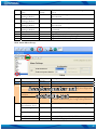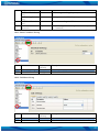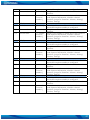
1
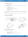
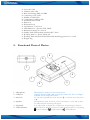
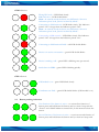
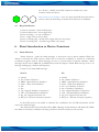
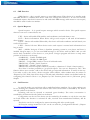
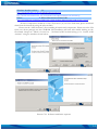
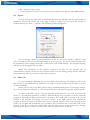
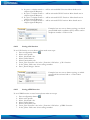
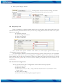
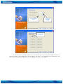
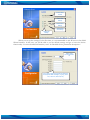
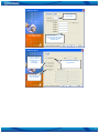
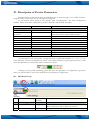
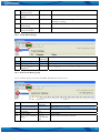
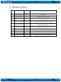
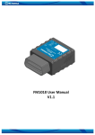
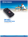
GH1201
Handheld GPS Tracker
User Manual v1.03
Table of Contents
1.
About Document ......................................................................................................................................... 4
1.1
Short Description................................................................................................................................ 4
1.2
Legal Notice......................................................................................................................................... 4
1.3
Contacts................................................................................................................................................ 4
2. Package Contents ......................................................................................................................................... 5
3. Device Assembling ...................................................................................................................................... 5
4. Device Characteristics ................................................................................................................................. 5
5. Functional Parts of Device ......................................................................................................................... 6
5.1
Indication of the device ..................................................................................................................... 7
5.2
Button pushing indication ................................................................................................................. 8
5.3
Beep Notification................................................................................................................................ 9
6. Short Introduction to Device Functions .................................................................................................. 9
6.1
Alarm Function ................................................................................................................................... 9
6.2
SMS Function ....................................................................................................................................10
6.3
Special Requests ................................................................................................................................10
6.4
Call Function .....................................................................................................................................10
6.5
GPRS Function .................................................................................................................................11
6.6
Modem Emulation Function...........................................................................................................11
6.7
Geo-Fence Function ........................................................................................................................11
6.8
Silent Call Function ..........................................................................................................................11
6.9
Track Log Function..........................................................................................................................11
6.10 Notification about Battery Level ....................................................................................................12
6.11 NMEA Function...............................................................................................................................12
6.12 Maps....................................................................................................................................................12
7. How to Start?..............................................................................................................................................13
7.1
Connecting to the PC.......................................................................................................................13
7.2
Software Installation.........................................................................................................................13
8. Introduction to the GPS Assistant Software .........................................................................................15
8.1
Show Location on Map....................................................................................................................17
8.2
Edit User’s Data................................................................................................................................18
8.3
Copy Track from Device .................................................................................................................18
8.4
Import Settings File ..........................................................................................................................20
8.5
Write Settings to Device ..................................................................................................................20
8.6
Sending NMEA.................................................................................................................................20
8.7
Changing Device Settings by SMS .................................................................................................20
8.8
Option ................................................................................................................................................22
8.9
PIN Code ...........................................................................................................................................22
8.10 Keyboard Settings.............................................................................................................................23
8.10.1
Setting SMS function...............................................................................................................23
8.10.2
Setting Call function ................................................................................................................24
8.10.3
Setting GPRS function............................................................................................................24
8.11 Request by Call..................................................................................................................................25
8.12 Geo-Fence Configuration................................................................................................................25
9. Simple Device Configuration ...................................................................................................................26
9.1
Full Functionality ..............................................................................................................................26
9.2
Simple Mobile Configuration..........................................................................................................33
9.3
Simple GPS Data Saver....................................................................................................................34
10.
Description of Device Parameters......................................................................................................35
2
10.1 GPS Menu Group.............................................................................................................................35
10.2 Track Menu Group...........................................................................................................................36
10.3 Geo-Fence Menu group...................................................................................................................36
10.4 GSM Menu Group ...........................................................................................................................37
10.5 GPRS Menu Group..........................................................................................................................37
10.6 APN Menu Group............................................................................................................................38
10.7 Server Menu Group..........................................................................................................................38
10.8 SMS Menu Group.............................................................................................................................39
10.9 Keyboard Menu Group ...................................................................................................................39
10.10
Alarm Menu Group .....................................................................................................................40
10.11
Silent Call Menu Group...............................................................................................................41
10.12
Call Menu Group..........................................................................................................................41
11.
Technical support..................................................................................................................................43
12.
Changes Log Sheet ................................................................................................................................44
3
1. About Document
1.1
Short Description
Teltonika Handheld GPS/GSM Tracker GH1201 is a GPS receiver with integrated GSM
modem. The device is designed for tracking and protecting people, assets and animals. The GPS
receiver allows finding out the coordinates of the device and forwarding them to an authoritative
person or to a Monitoring Centre. The device can also be used as a mobile phone as it has voice
transferring possibility.
1.2
Legal Notice
Copyright © 2007 TELTONIKA Ltd.
All rights reserved. Reproduction, transfer, distribution or storage of parts or all of the
contents in this document in any form without the prior written permission of TELTONIKA Ltd is
prohibited. Other product and company names mentioned herein may be trademarks or trade names
of their respective owners.
1.3
Contacts
If you encounter any problems when using our products, and cannot solve them by yourself,
please contact our technical support team by writing an e-Mail to [email protected] . We will be
pleased to help you.
4
2. Package Contents
GH1201 is supplied in a carton with all contents which are needed for the connection to a PC
and normal work handling:
ª
ª
ª
ª
ª
ª
GH1201 device
3.7V Li-Ion or Li-Pol battery
Cable „USB – mini USB“
CD with User’s Guide, Drivers and Software
Quick Start Guide
Power Charger
Notice: The producer does not provide a SIM card among other items of a package, which is
necessary for the connection to a GSM Network! You can obtain a SIM card from your local GSM
Service Provider.
If
any
of
the
components
is
missing
please
contact
your
local
Distributor.
(http://www.teltonika.lt/en/pages/Distributors)
3. Device Assembling
1
2
3
4. Device Characteristics
GH1201 housing is made-up of plastic.
ª
ª
ª
ª
GPS receiver SiRF Star III 20 channel
GPS antenna: Internal
GSM frequency: GSM 900/1800 MHz and 850/1900 MHz
GPRS Class 10
5
ª
ª
ª
ª
ª
ª
ª
ª
ª
ª
ª
ª
ª
ª
ª
ª
Voice call: YES
Vibration Call: YES
Data transferring: SMS or GPRS
Connecting to PC: USB
NMEA via USB: YES
Configuration: SMS or USB
Internal memory: 1MB
Buttons: 6
Keyboard Lock
Accumulator: 3.7V Li-Ion
LED indicators: 3 (Power, GPS, GSM)
Dimensions [mm]: 91 x 44 x 19
Standby Time GPS module switched OFF: 336 h.
Working Time on „Track“ Mode: 6 h.
Working Time with Periodical GPS module Switching (period: 1 h.): 120 h
Weight: 80g
5. Functional Parts of Device
6
5
7
4
1
2
1 – Microphone
2 – USB port
3 – Key lock
4 – Speaker
5 – Keyboard
6 – LED indicators
3
Microphone is used for voice conversations
Connect the mini USB cable to the device and to the PC to configure
GH1201 and to charge the battery
To lock the keyboard move the arrow to±; to unlock move the arrow
to²
The Speaker is used for active voice conversation – to be able to hear
the caller and for incoming call signals
You will enable or disable the set functions by pressing the buttons
LED indicators will let you know in what mode the device is operating.
- Power indicator, - GSM indicator, - GPS indicator
6
7 – ON button
5.1
To turn the device on, press and hold the button until Power LED
indicator turns green
Indication of the device
In order to detect in which mode the device is working you need to determine the LED
indicators state. Please read the „Power“ LED indications state description if „Power“ LED is on or
blinking.. If „GSM“ LED is on or blinking you need to read „GSM“ LED indications state
description. If „GPS“ LED is on or blinking, please read „GPS“ LED indications state description.
Each state indicator consists of 2 LEDs where one indicates the error (red) and another
indicates the process (green).
Exception is red “GPS” LED during the „Alarm“.
Indicators state description consists of state name (blue text) and short description (common
text of user manual).
Alarm – Red LED indicator is blinking and once per minute the device
sends vibrating signal. (For green LED indications read in “GPS
Indicators”).
Power indicators
The device is off – Indicators are off and the device does not react to
any button.
The device is in stand by mode – Indicators are off but the device
reacts to buttons (in case of GSM network loss – green LED is on; in
case of SIM card missing – red LED is on).
Battery level is low – LED is double blinking.
Device is turning off – both LEDs turns on.
Battery is fully charged – green LED is constant. (When the device
charging)
Battery level is high – LED is blinking. (When the device is
disconnected from the PC).
Battery is charging – LED is blinking. (When the device is connected
to the PC)
7
GSM indicators
Wrong PIN code – LED blinks slowly.
SIM card error – LED double blinks.
Note – in stand by mode the device acts differently. About its
indications please read „Device in Stand by Mode“.
Connecting to GSM network – LED blinks slowly. The Indicator
period “On” is longer than the Indicator period “Off”.
Note – in stand by mode the device acts differently. About its
indications please read „Device in Stand by Mode“.
Connected to GSM network – LED blinks slowly. The Indicator
period “Off” is longer than the Indicator period “On”.
Connecting to GSM network failed – red LED double blinks.
Device is in active conversation – green LED double blinks.
Device is making a call – green LED is blinking once per second.
Sends data via GPRS – green LED is blinking quickly.
GPS indicators
GPS module is on – green LED blinks slowly.
Coordinates are fixed – green LED double blinks. (GPS module is on)
5.2
Button pushing indication
First function of the button is active – to activate first function of
button press and hold down the button until you hear a beep with the
“Power” and “GSM” indicators turned ON, at this moment release the
button.
Second function of the button is active – to activate second function of
button press and hold down the button until you hear two beeps with
8
the “Power”, “GSM” and “GPS” indicators turned ON, at this
moment release the button.
Both functions are disabled – then you press and hold down the button
until you hear the third beep. It means both functions are disabled.
5.3
Beep Notification
Function activated – short double beeps.
Function deactivated – short single beep.
Device restarting – no any notification.
Error – single short, low tone beep.
Device is turning ON – double short, hight and low tone, beeps.
Device is turning OFF – double long, similar tone, beeps.
6. Short Introduction to Device Functions
6.1
Alarm Function
Alarm Function - sends the alarm messages to more than one set phone number. When the
Alarm is activated, the GPS receiver, which tries to track the coordinate, is turned on. Calculated
coordinates together with an Alarm message are sent to several earlier set phones numbers. Alarm
messages can be sent by SMS and via GPRS. Please read the chapter “Alarm Menu Group” how to set
message sending type, number and frequency.
Format of an Alarm SMS message:
Fix
No Fix
ª
ª
ª
ª
ª
ª
ª
ª
ª
ª
Alarm!
Id: <Name of Device>
IMEI: <Special Device Number>
Time: <Time from Satellites>
Fix:
Sat:
Op: <Special Number of Operator>
Cell: <Cell Identification Number>
Sig_Lvl: <Signal Level max 32>
Bat_Lvl: <Percent of battery Capacity>
ª
ª
ª
ª
ª
ª
ª
ª
ª
ª
Alarm!
Id: <Name of Device>
IMEI: <Special Device Number>
Time: <Time from Satellites>
Fix: <Coordinates of device>
Sat: <Number of Satellites>
Op: <Special Number of Operator>
Cell: <Cell Identification Number>
Sig_Lvl: <Signal Level max 32>
Bat_Lvl: <Percent of battery Capacity>
If the GPS receiver was unable to calculate the coordinates, the Cell ID information will be
sent in the Alarm message.
The Alarm mode can be switched off by SMS. (Message format alarm:on and alarm:off). While
the Alarm is activated, coordinates are being saved into the device memory each second.
9
6.2
SMS Function
SMS function – this is specific answer to users SMS request. When device is in standby mode
and SMS function is enabled, then device reads user settings and executes it. If user has correctly
formulated request, then device executes its and sends back SMS message with answer to user request,
this SMS is send to earlier set number.
6.3
Special Requests
Special requests – It is special request messages which controls device. The special requests
what user can use to control device are:
FIX? – device will enable GPS module, read coordinates and send them to user.
INF? – Device information. When device will get such request it will send all information
about it status
GEO? – Device will enable GPS module, after that it will read coordinates and will check your
set Geo-Fence zone.
LIFE? – Device life time. When device receive such request it returns back information how
long it works.
MN? – (Mobile Navigon) If there is Symbian operating system in your phone and there is
installed Navigon maps, so you can send SMS message to the device with text MN? And you will
receive back coordinates of the device to your phone. Navigon program will show on map exact
position of the device on the map.
ALARM:ON – Enable ALARM signal.
ALARM:OFF – Disable ALARM signal.
TRACK? – Using GPRS it sends to server all collected tracks.
TRACK:ON – Enable „Track“ function.
TRACK:OFF – Disable „Track“ function.
TRACK:ON,<interval of point collection (seconds)>,<duration of “Track“ function(min.)>
Also there is another possibility to get special request. You can use “Request by Call”. This
function allows user to make a call to the device and get requested information. It works in this way.
User make a call to the device, device recognize caller number, caller number must be written in
“Request by Call” field, then device drops a call and sends information which user defined earlier by
configuring this function. How to set „Request by Call“ function please look in (Call menu group)
chapter.
6.4
Call Function
In stand by mode you can initiate calls to predefined phone numbers. Up to eight numbers can
be set, meaning two numbers with each button. The active conversation is cancelled by the button
with red symbol on the button.
Incoming calls can be rejected or answered (green handset). The active conversation is
cancelled by the button with red symbol on the button.
Configuration can be set if the device can be reached by all numbers or only by the ones that
are listed. When this function is activated all calls, received from unauthorized numbers, will be
rejected.
The device can also be configured to answer incoming calls after several signals.
All function settings mentioned “Call” can be set with the „Configuration Wizard“. (Chapter
Description of Device Parameter)
10
6.5
GPRS Function
When this function is activated, the device start connects to server (TCP/IP protocols) and
sending data via GPRS, sends Track Logs and Regular Logs. When the transfer is completed, the
memory is cleared. If the device has no data stored, the data sending via GPRS will not start.
Also you can request „GPRS function“ by SMS. In order to do this, type „Track?“ and send it
to the device. The device will check if the sender phone number is stored within the “SMS Request
Authorized phone numbers” list. If the sender number has not been stored in the list the device will
ignore the SMS. Otherwise it will be checked if the SMS correct. If the SMS is correct the device will
send data to the server. After sending the date the device will clear its memory. If the sending was not
successful the memory will not be cleared. If the server parameters have been set incorrectly the
sending of data will be cancelled, the device memory will not be erased.
6.6
Modem Emulation Function
GH1201 can be connected to the PC through the USB port and after activating „Modem
Emulation” function, it can be used as normal GSM/GPRS USB modem. When this function is
activated the device can be controlled by AT commands. „GPS Assistant“ program will allow the user
to view all sent and received SMS messages in „Inbox“, „Sent Item“ or „Saved Item“ windows.
6.7
Geo-Fence Function
This function shows in which set Geo-Fence zone the device is located. The user can set up to
ten zones and is able to dedicate different names to them.
Within the configuration menu the zone name, centre coordinates, radius (in meters) and
thickness can be set. Each zone can have an activation schedule with time and date settings.
After the function has been activated by the button, the device will start to check if the GeoFence zone has been crossed. If the crossing was detected (both ways), the device will send a SMS
message to the first number, that has been set within the Alarm configuration (Chapter Alarm
Function)
If the device receives a request „GEO?“, it will check the zone where it is located and if the
zone was named – the name will be sent to the users. If no zone will be detected, the device will sent a
message where the zone will be named as “not available” (N/A).
6.8
Silent Call Function
„Silent Call“– is a function, when a call is activated without any local GH1201 user interaction.
Please send a SMS to the GH1201 to activate this function (message “SPY“). GH1201 receives this
message and compares the sender number with the numbers in the “SMS Request Authorized phone
numbers” list. If the sender number is not added in this list the device will ignore the SMS request,
otherwise the device recognizes the command and initiates a call to the number from which the SMS
was sent without informing the device keeper about this activity.
6.9
Track Log Function
Each GPS coordinate request is stored within the internal memory of the GH1201. In this way
the device makes a track history which can be reviewed later on the PC. Each stored point has the
following information:
ª
ª
Date
Time
11
ª
ª
ª
ª
ª
ª
ª
ª
ª
Langitude (i.e. 54,123456)
Longitude (i.e. 25,123456)
Altitude [m]
Direction
Speed
Number of Satellites
Cell ID
GSM Signal Level. (max 32)
Operator.
The information is stored within the device memory. When the memory gets full, the newest
record will be overwritten on top of the oldest (FIFO – First in, First Out). In that case, only the
newest information is stored.
All data, stored within the memory, may be exported to the PC using the USB connector. For
this matter the “GPS Assistant” program has to be used.
The device has 1MB internal memory space for storing the track log and is able to store up to
16.000 records within the memory.
6.10 Notification about Battery Level
GH1201 can inform about battery level status by SMS messages. This function is optional.
Depending on how the configuration was done, the device will send a SMS message to the first set
number within the Alarm configuration (Chapter Alarm Menu Group).
6.11 NMEA Function
This function allows tracking the real time location of the device within digital maps. This
function works only when the device is connected to the PC through the USB port. As soon as the
cable is unplugged – the function automatically turns off. When the function is activated GH1201
gives its NMEA code, which is recognized by the digital maps for navigation. To connect to digital
maps you need to set the correct speed. You can set data transferring speed using the program “GPS
Assistant” in the “Main” menu.
6.12 Maps
The program automatically finds installed digital maps on the user‘s PC. When the user has
installed more than one digital map on the PC, the program will detect all of them and the user can
choose one of them. The Program currently supports these maps:
ª Map Point
ª Akis (Lithuanian)
ª Google Earth (The user can export track files to this map. (Chapter Copy Track from
Device)
12
7. How to Start?
ª
ª
ª
ª
ª
Insert a SIM card.
Install the required drivers and software on your PC. (Chapter Software installation)
The internal battery of the device has to be fully charged. (Usually it can be charged by
connecting the device to the PC through the USB port, but you also can charge it using
other accessories).
Switching ON the device: In order to do this connect device to USB port and it will
switch ON automatically. Another way is to push and hold the button located on top of
the device until green LED turns on, release the button when LED glows. (The first
time before you turn ON the device is recommended to press restart button. It is
located in the hole behind alarm button.)
Set device parameters with the “GPS Assistant“ Software. (Chapter Short Introduction
to Device Function)
Note: The SIM card has to be used with deactivated PIN code request. The PIN code request
can be disabled with the help of a traditional mobile phone.
NOTE: TO TURN OFF DEVICE PUSH AND HOLD THE BUTTON LOCATED ON
TOP OF THE DEVICE UNTIL ALL GREEN LEDS TURNS ON, RELEASE THE
BUTTON WHEN LEDS ARE GLOWS.
7.1
Connecting to the PC
Before connecting the device to the PC, please install:
ª
ª
Drivers
“GPS Assistant” software
All required drivers and software are on the CD, which goes together with the device. If you
have an internet connection, please check for the latest software updates (www.teltonika.com). The
software version can be identified be going to Help -> About within the toolbar.
When the device is connected to the PC, the battery starts charging. The process is indicated
by the indicator located on the GH1201. (See Indication of the Device). When the device is
connected for the first time with an empty battery, the LED starts blinking only after some time.
If a bad SIM card is inserted or the device cannot detect it, the user will be informed about it
by a sound signal (3 short beeps) and will automatically restart and try to reconnect. After the third
indicator turns on (Chapter
reconnect attempt the device switches to stand by mode and the
Indication of the Device).
If the SIM Card will be inserted later, the device has to be restarted.
7.2
Software Installation
Minimal system requirements:
Operating system:
MS Windows 2000 SP3 or MS Windows XP SP1
Disc space:
Minimal screen resolution:
20 MB
1024 x 768 (Full Screen)
http://www.microsoft.com
13
Windows Installer version:
3.0
Component:
MS .NET framework 2.0
Driver:
Silicon Laboratories CP210x USB
http://www.download3k.com/DownloadLink1-UWin-Installer.html
http://213.226.139.30/Downloads/tavl/Tavl%5FClient/Net%5F2.0%5Fframework/dotnetfx.zip
http://www.silabs.com/tgwWebApp/public/web_content/products/Microcontrollers/USB/en/mcu_vcp.htm
All these components should be on the CD, however, if you fail to find them, please download
them from the internet by using the relevant links.
Please run the “GPS Assistant” after installing all mentioned components. Please insert the CD
from your device package into the CD-ROM. The Installation will start after double clicking on the
file named “Setup.exe” which is located on …\Software\GPS Assistant\Setup_1.0.x . Install “GPS
Assistant” using the windows shown below:
2
1
4
3
Pictures 7.2.1 Software installation sequence
14
When the installation is completed successfully, please double click on the „GPS Assistant“
icon located on the desktop to run the program.
8. Introduction to the GPS Assistant Software
To run this program, please activate the „GH1201 GPS Assistant“ link. When the program is
loaded, the main desktop with different zones is displayed:
ª
ª
ª
ª
ª
ª
Three main menu groups A
Users configuration B
Menu buttons C
Dynamic menu (changes accordingly to chosen menu group) D
Display field of chosen menu E
Status field F
Picture 8.1. „GPS Assistant“ program desktop
ª
In field A you can choose between the three main groups:
i. Maps – digital maps that display coordinates of the device;
ii. SMS – operations with SMS (sending, receiving, forming);
iii. Configuration – device configuration (through USB or by SMS).
15
Picture 8.2. Menu group field
Field B describes the System Users (devices).
Picture 8.3. Users’ description field
Field C consists of buttons that show the most common menu directories. Their meanings are
displayed when the mouse cursor is placed above the icon.
Picture 8.4. Control buttons field
Field D displays additional control buttons accordingly to the chosen menu group.
Picture 8.5. Additional control buttons field
16
Field E displays main information of the chosen menu group (maps or device
control/configuration tools).
Picture. 8.6. Main functions setting field
Field F displays the connection information of the devices.
Picture 8.7. Display field of external devices
8.1
Show Location on Map
You can view the device coordinates received after request or Alarm in the map with the help
of the program „GPS Assistant“.
To do so, you have to:
ª Run the program „GPS Assistant“. (by default the program should open the main
ª
ª
window. If not – click
maps)
Click “Tools” on the toolbar. Now the dialog select window will open.
Select „Show Location on Map…“. Please enter the coordinate latitude and longitude
in the opened window.
17
ª
8.2
Enter received data into the fields and click „Show“.
Edit User’s Data
When the device is connected to the PC for the first time, the program will ask if you want to
register the user (Chapter 8.2 Complete functionality), in such way you create the user, the data can be
configured later.
In order to change user’s data, you have to:
ª Run the program „GPS Assistant“.
ª Connect the device to the PC through USB port.
ª Click „Connect“.
ª Select „View“ in the standard menu.
ª In the opened dialog window select „Edit Profile“, or in menu buttons group click
ª
ª
8.3
“Profile”.
In the opened window click “Edit” to edit data, or click “Delete” if you want to delete
the user.
After clicking “Edit“ in the opened window you will be able to change user name
„Name“, phone number „Phone No.“ and you can see the „IMEI“ number of the
device and the driver version “Version“.
Copy Track from Device
The device has 1MB internal memory space where it can keep track history in coordinates. To
transfer this data from the device to the PC, you need to:
ª Run the „GPS Assistant” program.
ª Connect the device to the PC through USB port.
ª Click „Connect“.
ª Select „View“ in the standard menu.
ª
Select „Track Log“ in the opened window or click on
„Track Log“ window will open.
in menu buttons group. The
18
ª
Click „Copy Track“. (The arrow placed on the right side of Copy Track button allows
to choose data which you want to copy to the PC. ( „Track Log“ – track data; „Regular
Points“ – GPS receiver connection data; „Alarm Points“ – data select upon „Alarm”
signals.)
Note: If – in copy progress – an error window (picture. 8.3.1.) appears, click “OK“ to view it.
Possible solutions: optimize track by increasing distance between points (8.3.2 picture. A) or increase
displayed point number to maximum (8.3.2 picture. B).
Picture 8.3.1 Error window
Chapter 10
(b)
Picture 8.3.2 Data filter and display window
ª
After finishing to copy data from the device to the PC, you will be asked if you want to
save them (pressing “Yes“ will save all copied data in your selected name; pressing
“No“ will cancel the saving procedure).
In the “Track Log“ program window, the user can filter copied data by date and time. To view
data of a specific period, enter date and time in fields ”From“ and “To“. When the period is set, please
click ”Apply“. Only the selected period data will be displayed. Data can be:
ª Saved in program (“Save Track“ button)
19
ª
ª
Formed data archive with specific file format (“Export“ button)
Displayed on the Google Earth map (“Open KML File“ button)
Note: „Open KML File” button is active only if you are using the freeware „Google Earth“
installed on your PC.(It can be downloaded form http://earth.google.com/download-earth.html).
Within the program saved data can be displayed on the map by clicking the button “Show“.
Created data archive can be sent to the other users, who can view them with “GPS Assistant“,
„Microsoft Excel“ or other programmes that support (*.xml) file format.
To clear the data from the device, click “Clear Log” button. To delete the data saved in the
program click “Delete”, to rename it – “Rename”.
8.4
Import Settings File
To import settings file into the program, the user has to:
ª Run “GPS Assistant“ program.
ª Connect the GH1201 to the PC through the USB port (The user does not have to
connect the device if he wants to see the settings. However, if the user reads the
settings from the file first and connects the device later, the program will read values
from the device and rewrites those read values from the file).
ª Click button “Configuration“.
ª Select “Load Configuration from File“ in the standard menu.
ª In the opened window select configuration file and click ”Open“.
ª The file with the settings will be imported into program.
8.5
Write Settings to Device
To write setting into device, the user has to:
ª Run “GPS Assistant“ program.
ª Connect the device to the PC through the USB port.
ª Click the button “Configuration“.
ª Press the button “Handheld GPS” in the standard menu and choose “Send Changes”.
ª After data transferring the device will restart itself.
8.6
Sending NMEA
If you want to connect GH1201 to the digital map and see its location in real time you should
set NMEA data sending baud rate to be similar like in the digital map. Where to set NMEA baud rate
of device you can find by pressing “Configuration” in the “Mine” menu. (Chapter Description of
Device Parameters). Than you need to set the NMEA function on one of the buttons within GH1201
and start to send the NMEA data by pressing the button. To set the NMEA function on button you
can use „Configuration Wizard“ or in Configuration ->active profile -> keyboard. (Chapter Keyboard
menu group).
8.7
Changing Device Settings by SMS
The device settings can be changed by sending a SMS message with setting parameters and
special commands initiating changes of the device configuration. Settings in the device can be changed
one by one, or all at the same time. The easiest way is to use a GSM modem connected to the PC. The
modem can be connected to the program “GPS Assistant” and can send SMS messages to the
GH1201 just with one “Send“ button click. SMS message parameters consist of:
20
CFG (special command) 1 (profile number);GPS: (settings group) 1,180,0,0,10,60,1,~,~;(parameters value)
Another possible way is to send a SMS message with configuration command, profile number,
settings group and parameters to the GH1201 by a mobile phone (message text example:
CFG1;TRACK:2,60;)
The program “GPS Assistant” can form you a sending text. Each setting group in the profile
has a “Configuration Thought SMS“ window (picture 8.5.1), where you can see the specific
configuration message text by clicking a “Replace“ button.
Picture 8.5.1 SMS settings window
When moving to another configuration group and changing parameters there, the values can
be joined to the previous SMS text by clicking the button “Append”. Below you will find text field
information about left characters, messages number, SMS receivers name and number.
Example:
CFG1;GEO1:1,Kaunas,54.94292,23.96668,1268,572,127,0,1439;
CFG – Special command to configure GH1201 through SMS
1 – Active profile number
; - Separator
GEO – Function name that you want to configure
1 – Geo-Fence zone number (zone counting start at 0 to 9)
: - Separator
1 – Zone enable (ON- 1, Off- 0)
, - Separator
Kaunas – Zone name (in this case a city name)
, - Separator
54.94292 – Latitude
, - Separator
23.96668 – Longitude
, - Separator
1268 – Geo-Fence radius (In SMS 1 means 10 meters so you should now that if you will enter
1268 it means 1268*10 = 12.680 m)
, - Separator
572 – Geo-Fence fence thickness (In SMS 1 means 10 meters so you should now that if you
will enter 572 it means 572*10 = 5.720 m)
, - Separator
127 – Week days (All days) (each day is assigned a unique number, this number indicates which
day has been marked. Monday – 2, Tuesday – 4, Wednesday – 8, Thursday – 16, Friday – 32, Saturday
– 64, Sunday – 1. If you want to mark multiple days, for example Wednesday and Thursday, you
should enter the numeric sum of those days (8+16=24) ).
, - Separator
0 – Start time (min) (00:00)
, - Separator
21
1439 – End time (min) (23:59)
; - Need separator if you want to set up another Geo-Fence zone with the same SMS message.
8.8
Option
You can change the visual view of transferred data from the GH1201 and the synchronization
parameters between the device and a PC using “Options” settings. You can open this window in
standard menu press Tools -> Options. The following window will appears.
You can change “Track” showing parameters in the first tab of the window „Options“. And
you can change the Geo-Fence showing parameters in the next tab. The device synchronization with
PC parameters can be changed in the tabs “GPS device” and “GSM modem”. The program language
and time can be changed in the tab „Misc“.
Note: The parameters in the window „Options“ are only for the program and its
synchronization with the device, but not for device itself. If you are writing settings into the GH1201,
these parameters will not be written into the device memory.
8.9
PIN Code
If you are inserting a SIM card with an active PIN code request into the GH1201, it will not be
able connect to the GSM network. Therefore you need to remove the PIN code. In order to do this
are two possibilities:
Either you can remove the PIN code by using a standard mobile phone via its security settings.
Or you can connect the GH1201 to a PC and enter the PIN code with the program „GPS Assistant“.
To remove the PIN code by using the program „GPS Assistant“ you need to connect the
device to a PC and press the button „Connect“. Then the device tries to connect to the PC, while the
program is checking the SIM card inserted in the device. If no SIM card is inserted at all you can
connect to the program and change the device settings. If the SIM card has been inserted the
program continues to check if the PIN code has been correctly entered.. If the code is missing or not
correct, the program will aromatically open a window with a field were the correct PIN code can be
entered. If you do not know the correct PIN code, but only want to change some device settings,
please press the button “Cancel” and the device will successfully connect to the PC.
22
8.10 Keyboard Settings
Device have six buttons, functionality of each button can be configured. Each button can have
two functions. About functionality of buttons please read chapter Device functionality. To set first
function of the key make next steps:
Setting first function of key
Press configuration button .
Select active profile.
Select „Keyboard“ tab.
Select wanted button. (1)
Select Functionality tab. (2)
From „First Function“ tab, in the „Function“
field select wanted function. You can press down
arrow to see all available functions. (3)
7. „Data“ field is filled depending on selected
button function
1.
2.
3.
4.
5.
6.
Setting second function of key
1.
2.
3.
4.
5.
6.
Press configuration button .
Select active profile.
Select „Keyboard“ tab.
Select wanted button. (1)
Select Functionality tab. (2)
From „Second Function“ tab, in the „Function“
field select wanted function. You can press down
arrow to see all available functions. (3)
7. „Data“ field is filled depending on selected
button function.
8.10.1
Setting SMS function
To set SMS function to exact button please make next steps:
1. Press configuration button
.
2. Select active profile.
3. Select „Keyboard“ tab.
4. Select wanted button.
5. Select Functionality tab.
6. From „First Function“ tab, in the „Function“ field select SMS function.
7. In the „Data“ field enter particular data:
a. 0<space><telephone number> - will be activated INF? Function. More details are in
chapter (Special Request).
23
b. 1<space>< telephone number > - will be activated MN? Function More details are in
chapter (Special Request).
c. 2<space>< telephone number > - will be activated GEO? Function. More details are in
chapter (Special Request).
d. 3<space>< telephone number > - will be activated LIVE? Function. More details are in
chapter (Special Request).
e. 4<space>< telephone number > - will be activated FIX? Function. More details are in
chapter (Special Request).
Example: here we can see button settings, on which
pressed SMS with coordinates (FIX) will be send to
telephone number +37011111111.
8.10.2
Setting Call function
To set Call function to exact button please make next steps:
1. Press configuration button
.
2. Select active profile.
3. Select „Keyboard“ tab.
4. Select wanted button.
5. Select Functionality tab.
6. From „First Function“ tab, in the „Function“ field select „Call“ function.
7. In the „Data“ field enter server settings number
8. Press „Send Changes“ button
Example: here we can see button setting, on which
pressed will be activated call to +37011111111
number.
8.10.3
Setting GPRS function
To set GPRS function to exact button please make next steps:
1. Press configuration button
.
2. Select active profile.
3. Select „Keyboard“ tab.
4. Select wanted button.
5. Select Functionality tab.
6. From „First Function“ tab, in the „Function“ field select „GPRS“ function.
7. In the „Data“ field enter server settings number
24
8. Press „Send Changes“ button.
Example: here we can see button settings, on which
pressed all data will be send to first server.
8.11 Request by Call
Here is available to set phone number witch from you can call to device, device will reject your
call and will make particular function witch you can set up using GPS Assistant. In order to set up this
function you should:
ª Start GPS Assistant
ª Click Configuration button
ª Select active profile
ª Select Call function
You should enter phone number from witch you will request special function (i.e.
+37062212123) in the (1) position.
You should select function you want in the second (2) position. Press arrow to see all available
list of functions. And the last step is entering phone number for answer from device to destination
phone number. If you will choose function as Alarm On, Alarm Off, Track On, Track Off you should
leave clear the third (3) field. If you choose function GPRS you should enter servers number in the
third field (3).
8.12 Geo-Fence Configuration
To set your Geo-Fence click ”Configuration“ in the buttons menu group and:
ª Select active profile.
ª Select Geo-Fence.
ª Select active zone (f.e.. GF (1-ON)) with the name that has to be entered in “Zone
Name“ field.
ª Click “Select on Map“.
ª Mark the zone by following the program requests.
25
ª
ª
Click “Done“. (Program will automatically enter the marked zone centre coordinates to
”Geo-Fence Centre Latitude“ and “Geo-Fence Centre Longitude“ fields and its radius
into “Geo-Fence Radius“ field)
Enter zone thickness into field “Geo-Fence Fence Thickness“. (Recommended zone
thickness is 40-60% of zone radius).
Select “Write to device” if the device is connected to the PC or save to file if the device is not
connected.
9. Simple Device Configuration
9.1
Full Functionality
ª
ª
ª
ª
With a left mouse button double-click on the “GPS Assistant„ icon the main Assistant
program window will open.
Connect the GH1201 to the PC and wait until the PC recognizes the device.
Click “Connect“ in “User“ field.
If the device is connected to the program for the first time, the following window will
open:
Click Yes
Enter the name of
the device
Enter the phone
number of the
device
ª
Click Create
When the device has been connected to the PC, a GPS Asistant Configuration Wizard
window will open. It will help to enter the essential data.
26
Time zone
User name of the
device
Device melody
Ring level of the
device
Speaker level of the
device
Enable GPS
module
Choose “Fix”
setting
Choose “Tracking”
setting
Choose “GeoFencing” setting
It is recommended to tick all the boxes in Configuration Wizard window if the parameters are
set for the first time.
Unpick this function
Set automatic
module switching
on interval
27
Set track logging
duration
Set the track
point update
interval
Enable and
name the GeoFence zone
In the Geo-Fence wizard window you can activate up to ten zones and dedicate names to
them. To make a full configuration of the settings, you have to use detailed device parameters (10.3
Geo-Fence menu group) settings. How to configure Geo-Fence read chapter
28
Enable GSM
module
Select SMS
settings
Select Alarm
settings
Select Silent
Call settings
Select Call
settings
When you set up the settings for the first time, it is recommended to tick all boxes in the GSM
Wizard window. In this case you will be able to see the default settings and get to know the device
functionality. For more detailed information, read “10. Detailed device parameters description“.
Switch SMS
sound notification
off
Form users numbers list that will be allowed to
send request SMS messages. (e.g. Spy; Geo?;
Fix?; Alarm:on; Alarm:off, etc.)
29
Set Alarm
sending method.
Set time for
sending Alarm
messages.
Set Alarm
messages
sending period.
Select to receive
or not a
notification about
battery level
Create a list of users who
will be able to get Alarm
messages
If you set the “Alarm“ message sending via GPRS, then you need to configure GPRS settings
by clicking “GPRS Settings“.
Note: GPRS settings such as Server IP Address, Server Port, etc. can be obtained from your
Server Service Provider. APN settings are to be obtained from your GSM Service Provider.
30
Enable Silent
Call function
Form numbers list that will
be able to use the function
by sending an SMS
request „SPY“
Tick if you want to
receive a minute
notification during
the voice
conversation
To disable auto answering,
untick the box.
Set incoming calls
from everybody
31
By default the middle button
is an Alarm
When you choose “Call” or “SMS” function, an additional field for a phone number will
appear. By entering a phone number you will assign a specific number to a particular button and you
will be able to call it by pressing this button. If no numbers will be entered, the chosen function will
stay inactive.
You can choose whether to write the settings into the device or to save them into a file for the
later usage on the last window “Configuration Wizard”. “Write to Device” will be inactive if GH1201
will not be connected to the PC.
32
9.2
Simple Mobile Configuration
Connect the device to the PC and run the program “GPS Assistant“. Click “Connect” and
enter the settings following the “Configuration Wizard“. With these settings you will be able to make a
phone call to four set numbers and receive a phone call from any number.
Configuration Wizard – Main window:
ª Ringing tune
ª Speaker sensibility
ª Ringing volume
ª Click “Next“ button
Configuration Wizard – GPS window:
ª Remove “Enable GPS“
ª Click “Next“ button
Configuration Wizard – GSM window:
ª Remove “SMS“
ª Remove “Alarm“
ª Tick “Silent Call“ (3.7 Silent Call)
ª Tick “Call“ (3.3 Call)
ª Click “Next“ button
Configuration Wizard – Silent Call window:
ª If you want to use the Silent Call (Silent Call Function) function – set ON, if not – set
OFF. If you choose to use the function, form a “SPY” request allowed phone numbers
list.
ª Click “Next“ button
Configuration Wizard – Call window:
ª Remove “Auto Answer“ (Recommended). If you decided to use ”Auto Answer“
function, in “After“ set the beeps number before the auto answering
ª Tick “Minute Minder“
ª In Caller Group select “Everybody“
ª Click “Next“ button
Configuration Wizard – Keyboard window:
ª Select “Call” function to all four buttons (Call Function ) and add a phone number to
them.
ª Click “Next“ button
On the last Configuration Wizard window:
ª Choose “Write to Device”
ª Click “Finish“ button
33
9.3
Simple GPS Data Saver
Connect the device to the PC and run the program “GPS Assistant“. Click “Connect” and
enter the settings following the “Configuration Wizard“. With these settings you will be able to collect
the track history and later view it on your PC with the program “GPS Assistant“.
Configuration Wizard – Main window:
ª Set the Time Zone according to the capital
ª Click “Next“ button
Configuration Wizard – GPS window:
ª Tick “Enable GPS“
ª Tick “Fix“ ( SMS Function )
ª Tick “Tracking“( Track Log Function )
ª Click “Next“ button
Configuration Wizard – Fix window:
ª Remove “Request Fix by Call“
ª In the field “Fix Update Interval” enter time period when the GPS module will switch
on to set the coordinates. (Recommended 60-120 min).
ª Click “Next“ button
Configuration Wizard – Tracking window:
ª In the field “Track Point Update Interval” enter the time period when the GPS module
will safe the track coordinates. (Recommended 10-30 sec)
ª In the field “Track Log duration” enter the time period when GPS module creates a
track log. (It is recommended to keep in mind the “Track Point Update Interval“ value)
ª Click “Next“ button
Configuration Wizard – GSM window:
ª Remove “Enable GSM“
ª Click “Next“ button
Configuration Wizard – Keyboard window:
ª Select the function “Track” to one of the buttons. The other buttons you can leave
blank by choosing ”None“
ª Click “Next“ button
On the last Configuration Wizard window:
ª Choose “Write to Device”
ª Click “Finish“ button
34
10. Description of Device Parameters
Detailed device setting can be done by SMS messages or with the help of the “GPS Assistant”
program, while connected to the PC through the USB port.
In the buttons menu group of the program, click ”Configuration“. The main configuration
window “Main“ with main configuration groups “General“ and “Sound“ will open.
Parameter
General Settings
PIN code
Enable password
protection
Time zone
Time Format
Vibration
ID
N/A message
NMEA baud rate
Sound Settings
Ring volume
Melody
Speaker volume
Value [default]
Description
****
************
Personal Identification Number
SMS security code. Then it is enable you should
enter this code in request SMS messages.
Time zone
Time format
Enable/ Disable vibration of device
Device owner name
Not Available data text
NMEA transferring baud rate
-12 - +12 [---]
Enable
16 symbols
16 symbols
4800 – 11500 bps
0-5 [3]
0-100 [50]
Ring volume
Ring tone
Speakers volume level
You can create your own profile, just press button on particular number “1”, “2” or “3” you
want and press “Set this configuration as active” this number becomes a green (picture below). It will
mean that parameters in this profile will be written into device.
Clicking on the profile numbering green will open the parameter “Configuration” group list
where you will be able to execute the detailed device parameters configuration.
10.1 GPS Menu Group
ID
Parameter
Value
[default]
Description
2/1
GPS Settings
Enable GPS
0-1[0]
Time How Long
0-9999[180]
Enable GPS module. If GPS module is disabled, the
device will not be able to detect its location.
Time period for how long the GPS receiver is trying to
2/2
35
2/4
2/5
2/6
2/7
GPS Trying Get
Position [sec]
Fix Update Interval
[min]
Fix Keep Time [sec]
Coordinates Life
Time [min]
Fix Auto Request
Phone Numbers
calculate the coordinates
0-65535
Sets the update interval for fixing the coordinates
0-65535
0-999
Time period for calculating the coordinates before
saving or sending
Coordinates life time
[---]
Fix auto request phone numbers (2 numbers)
10.2 Track Menu Group
ID
Parameter
3/1
3/2
Track Settings
Track update interval
Track logging
duration
Value
[default]
Description
Track update interval while operating in Track mode
Track logging duration while operating in Track mode
10.3 Geo-Fence Menu group
Up to 10 Geo-Fence zones are described. Parameters of each zone:
ID
5/1
5/2
5/3
Parameter
Geo-Fence Settings
Enable Geo-Fence
Function
Zone Name
GF Centre Latitude
[deg]
Value
[default]
0-1
[0]
[---]
+/- 0180.000000
[0]
Description
; Enable Geo-Fencing
Enable Geo-Fence function
Zone name
Geo-Fence zone centre latitude
36
5/4
5/5
5/6
5/7
5/8
5/9
GF Centre
Longitude [deg]
+/- 090.000000
[0]
GF Radius [m]
0-65535
[0]
GF Fence Thickness 0-9999
[m]
[0]
Week Days
[---]
Start Time
[---]
End Time
[---]
Geo-Fence zone centre longitude
Geo-Fence zone radius
Geo-Fence zone thickness
Active zone week days
Active zone start time
Active zone end time
10.4 GSM Menu Group
ID
Parameter
6/1
6/2
6/3
GSM Settings
Enable GSM
Auto Answer after
Beep Time
6/4
6/5
Call In Authorization
Call In Authorized
Phone Numbers
Value
[default]
Description
0-1 [1]
[0]
Enable GSM
Auto answer after set number of signals
In which second the user is informed about call
duration
Enable incoming calls filter function
Incoming calls authorized phone numbers
0-1 [Off]
10.5 GPRS Menu Group
ID
Parameter
7/1
LED Settings
GPRS Enable
Value
[default]
Description
0-1
Enable GPRS
37
7/2
7/3
7/4
Time How Long
Modem Trying
Connect GPRS [sec]
Dial Number
Data Send Period
[min]
[0]
0-9999
[120]
Time period for modem connection to the GPRS
[*99#]
[0]
Phone number to enable GPRS
Data sending period via GPRS
10.6 APN Menu Group
Four GPRS service descriptions can be made.
ID
Parameter
8/1
8/2
8/3
LED Settings
Access Point Name
APN Username
APN Password
Value
[default]
Description
[---]
[---]
[---]
APN name
APN user name
APN password
Value
[default]
Description
[---]
0-65535
[---]
0-65535
[---]
[---]
Server IP address
Server port number
10.7 Server Menu Group
ID
Parameter
9/1
9/2
LED Settings
Server IP address
Server port
9/3
Local port
9/4
User name
Local port number
Connection to the server user name
38
9/5
Password
[---]
Connection to the server password
Value
[default]
Description
0-9999 [60]
0-1
[0]
[---]
Message sending attempt time
Sound notification about received SMS message
10.8 SMS Menu Group
ID
10/1
10/2
10/3
Parameter
SMS Settings
SMS Time Out [sec]
SMS Sound
Notification
SMS Request
Authorized phone
numbers
Phone numbers that can send SMS commands to the
device (five numbers can be set)
10.9 Keyboard Menu Group
Each button is configured separately. Button parameters:
ID
12/1
12/2
12/3
12/4
Parameter
Keyboard Settings
Enable
Keyboard locking
First function
activation time [ms]
Second function
activation time [ms]
Value
[default]
Description
0-1 [1]
0-1 [0]
0-4000
[1000]
1000-5000
[3000]
Enable each button
Keyboard locking
First function activation time
Second function activation time (must be longer than
12/3)
39
12/5
12/6
12/7
12/8
12/9
12/10
12/11
12/12
12/13
Deactivation time
[ms]
First Function
Settings: Mode 1
First Function
Settings: Mode 2
Second Function
Settings: Mode 1
Second Function
Settings: Mode 2
Identical to ‘Mode 1‘
Frequency
Duration
Volume
1000-5000
[3000]
Function deactivation time (must be longer than
12/4)
First function settings while the device is
disconnected
First function settings while the device is connected
Second function settings while the device is
disconnected
Second function settings while the device is
connected
Settings identical to Mode 1
Signal frequency in button pushing
Signal duration in button pushing
Signal volume in button pushing
10.10 Alarm Menu Group
ID
Parameter
14/1
Alarm Settings
Enable fall detection
Fall Timeout
Enable moving status
detection
Stop Timeout
14/2
14/3
Enable Information
About Battery Level
Battery Charge Level
(1)
Battery charge level
(2)
Send Method
Max Time for Alarm
Value
[default]
Description
Fall detection
Time value, when the Alarm message is being sent
after fall detection and is not moving for a longer time
period than set
Movement detection
Time value, when the Alarm message is being sent if
the device is not moving for a longer time period than
set
Enable information about battery level sending
Battery charge level 1
Battery charge level 2
Alarm sending method: SMS, GPRS or both
Sent SMS message quantity
40
14/4
[min]
SMS Send Period
[sec]
Track Saving Period
[sec]
GPRS Send Period
[sec]
Alarm Destination
Phone No.
SMS messages sending frequency
Messages sent via GPRS frequency
Alarm data sending via GPRS
[---]
Alarm messages destination phone numbers (can be
set 5 numbers)
Value
[default]
Description
0-1 [0]
Enable Silent Call function
Value
[default]
Description
[Function]
The selected function will be activated when call is
10.11 Silent Call Menu Group
ID
Parameter
15/1
Silent Call Settings
Silent Call Function
10.12 Call Menu Group
ID
Parameter
17/1
Call (1)
Function
41
17/2
Phone number:
[+Number]
17/3
Function data:
[ + number
or server
number ]
17/1
Call (2)
Function
[Function]
17/2
Phone number:
[+Number]
17/3
Function data:
[ + number
or server
number ]
17/2
Call (3)
Function
17/2
Phone number:
17/3
Function data:
17/2
Call (4)
Function
17/2
Phone number:
17/3
Function data:
17/2
Call (4)
Function
17/2
Phone number:
17/3
Function data:
[+Number]
[ + number
or server
number ]
[+Number]
[ + number
or server
number ]
[ +Number]
[ + number
or server
number ]
received from phone number as configured.
The phone number which will activate the selected
function.
Phone/server number to which device will contact or
send requested information, related to selected
function. (except for functions: Alarm:on, Alarm:off,
Track:on, Track:off)
The selected function will be activated when call is
received from phone number as configured.
The phone number which will activate the selected
function.
Phone/server number to which device will contact or
send requested information, related to selected
function. (except for functions: Alarm:on, Alarm:off,
Track:on, Track:off)
42
11. Technical support
Problem: Data sent via GPRS didn’t reach the server.
Solution: Check if Server IP address, Server Port, Local Port, User Name, Password, APN,
APN User Name, APN password have been entered correctly. To enter them choose “Alarm” and
“GPRS Settings” in “Wizard Configuration“ or by detailed device configuration which can be reached
in menu buttons group „Configuration“-> active profile (green button with the number)->APN and
Server. If the data has been entered correctly, please check if the GPRS function is active and if the
server number has been entered properly into the field “Data“. Before entering the required data,
please read “Description of Device Parameters“ chapters 10.6 “APN Menu Group” and 10.7 Server
Menu Group.
Problem: Being in the set Geo-Fence zone, received SMS messages state object’s leaving and
entering of the zone.
Solution: As GPS system sets the object’s location with bias which is directly connected to the
satellites visibility (e.g. being in the building, tunnels, etc the bias will be higher than in open place)
there is a possibility, that the set zone radius is too little and it synchronizes or is smaller than the
object’s coordinate set by the satellites. In this case it appears as if the object is leaving the zone and
then entering it again (although it never has left it).
To avoid such situation, increase the Geo-Fence zone radius and set the correct zone thickness
value (5/6 Geo-Fence Fence Thickness). It should be as big as possible.
Problem: Alarm data not sending to server.
Solution: If GPRS method were chosen, Server parameters must be set. For Alarm events
Server should be described in Configuration Server (2) window. For other events Server must be
described in Configuration Server (1) window.
!!! IMPORTANT !!! If same server is used for Regular and Alarm points – different Local Port value
must be set
This sign on the package means that it is necessary to read the User Manual,
which is on the CD, before you start using the device.
This sign on the package means, that used electronic and electric equipment
should be stored separately.
If you have faced some problems using the device, which you are not able to solve by yourself, you are
always welcome to address our technical support department by e-Mail [email protected]. We will be
glad to help you.
43
12. Changes Log Sheet
Nr.
Date
1.
June 12, 2007
New
version
number
1.00
2.
June 12, 2007
1.00
3.
June 13, 2007
1.00
4.
June 20, 2007
1.02
5.
July 17, 2007
1.03
6.
July 24, 2007
1.03
7.
July 24, 2007
1.03
Changed first page picture.
Corrected dimensions. Chapter 4 Device
Characteristics
Added chapters 6.3 Special Request, 8.10 Keyboard
Settings and 10.12 Call Menu Group
SMS protocol is changed in Alarm Function chapter
and Track Log Function
Chapter 4 Device Characteristics added device
working time from battery.
Added Chapter 8.12 Geo-Fence Configuration
8.
July 24, 2007
1.03
Changed pictures of Chapter 10
9.
July 26, 2007
1.03
Device name changed
10.
July 26, 2007
1.03
Added information in the Chapter 7.
Comments
Corrected.
44