1
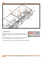
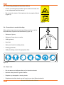
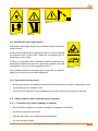
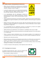
BRUTTUS 6000 Spreader Instruction Manual MANU-7006-ING Rev. B BRUTTUS 6000 SPREADER INSTRUCTION MANUAL STARA S/A - INDÚSTRIA DE IMPLEMENTOS AGRÍCOLAS CNPJ: 91.495.499/0001-00 Av. Stara, 519 - Caixa Postal 53 Não-Me-Toque - RS - Brazil - CEP: 99470-000 Telephone/Fax: (54) 3332-2800 e-mail: [email protected] Home page: www.stara.com.br August/2015 - Revision B MANU-7006-ING CONTENT Clicar FOREWORD........................................................................................................................................7 INTRODUCTION..................................................................................................................................9 1 - MAIN COMPONENTS................................................................................................................... 11 2 - IDENTIFICATION..........................................................................................................................12 3 - TECHNICAL SPECIFICATIONS...................................................................................................13 4 - Dimensions................................................................................................................................14 5 - SAFETY PROCEDURES..............................................................................................................15 5.1 - General safety procedures....................................................................................................15 5.2 - Know all safety information...................................................................................................15 5.3 - Preventing unexpected machine start-up..............................................................................16 5.4 - Precautions to work with safety.............................................................................................16 5.5 - Decal care ............................................................................................................................16 5.6 - Intended use.........................................................................................................................17 5.7 - Improper usage.....................................................................................................................17 5.8 - Operating and transporting the implement with safety..........................................................17 5.9 - Avoid fluids under high pressure...........................................................................................19 5.10 - Cares while on hilly terrain..................................................................................................19 5.11 - Safety measures while transporting the implement.............................................................19 5.11.1 - Transporting on public roadways or highway...................................................................19 5.11.2 - Transporting the implement on trucks or flatbeds............................................................20 5.11.3 - Lights and hazard indicators............................................................................................20 5.12 - Avoid heating parts near fluid lines ....................................................................................20 5.13 - Work in well ventilated areas..............................................................................................21 5.14 - Safety procedures when inflating tires................................................................................21 5.15 - Emergency procedures.......................................................................................................21 5.16 - Safety measures during implement maintenance...............................................................22 5.17 - Protecting the environment ................................................................................................22 6 - MAINTENANCE............................................................................................................................23 6.1 - Paint care and cleaning.........................................................................................................23 6.2 - Tire pressure.........................................................................................................................23 6.3 - Retightening and lubrication..................................................................................................23 6.4 - Chain drive guards................................................................................................................24 7 - ASSEMBLIES................................................................................................................................24 7.1 - Mounting the hubs, tires and rims to the axle.......................................................................24 7.2 - Mounting the wheel forks, the hitch and the wheel axles to the chassis...............................25 7.3 - Preparing the drive-train for transport...................................................................................25 7.4 - Mounting the deflectors.........................................................................................................25 7.5 - Mounting the product hoppers..............................................................................................26 7.6 - Mounting the conveyor belts................................................................................................26 7.7 - Output rate reducer assembly...............................................................................................27 7.8 - Load reducing caps installation.............................................................................................27 7.9 - Agitator assembly and operation...........................................................................................27 7.10 - Protective grating assembly and operation.........................................................................28 7.11 - Slide-gate and adjustment lever assembly..........................................................................28 7.12 - Transmission assembly installation.....................................................................................28 7.13 - Clutch drive cylinder assembly............................................................................................29 7.14 - Wind-breaker curtain installation.........................................................................................30 7.15 - Hydraulic hoses installation.................................................................................................30 7.16 - Variable rate application control system Installation (optional)...........................................30 7.17 - Row marker installation (optional).......................................................................................30 8 - OPERATION AND ADJUSTMENTS..............................................................................................31 8.1 - Stainless Steel Conveyor Belt Adjustments..........................................................................31 8.2 - Transmission chain-drive adjustment....................................................................................31 8.3 - Procedures for when maneuvering and handling the implement..........................................32 8.3.1 - Transport x load.................................................................................................................32 8.4 - Slide-gate adjustments..........................................................................................................32 8.5 - Procedure for changing gears in the gear box......................................................................33 8.6 - Implement leveling................................................................................................................33 8.7 - Tread gauge adjustment procedure......................................................................................33 8.8 - Procedure when using the row marker (optional).................................................................34 8.9 - Hitching-up to the tractor.......................................................................................................34 9 - TROUBLESHOOTING..................................................................................................................36 10 - APPLICATION RATE ADJUSTMENT TABLE FOR RUBBER CONVEYOR BELTS...................37 10.1 - Fertilizer - specific weight - 1.17 kg/m³................................................................................37 10.2 - Fertilizer NPK (w/reducer kit) - Specific weight 1.17 kg/m³.................................................38 10.3 - Fertilizer NPK (w/reducer kit) - Specific weight 1.17 kg/m³.................................................39 10.4 - Dry limestone - Specific weight 1.82 kg/m³.........................................................................40 10.5 - Dry limestone - Specific weight 1.82 kg/m³.........................................................................40 10.6 - Dry limestone - Specific weight 1.82 kg/m³.........................................................................41 10.7 - Dry limestone - Specific weight 1.82 kg/m³.........................................................................41 10.8 - Dry limestone - Specific weight 1.82 kg/m³.........................................................................42 10.9 - Dry limestone - Specific weight 1.82 kg/m³.........................................................................42 10.10 - Dry limestone - Specific weight 1.82 kg/m³.......................................................................43 10.11 - Fosmag (w/reducer kit) - Specific weight 1.10 kg/m³........................................................43 10.12 - Dry limestone - Specific weight 1.82 kg/m³.......................................................................44 10.13 - Fosmag (w/reducer kit) - Specific weight 1.10 kg/m³........................................................45 10.14 - Gypsum - Specific weight 0.094 kg/m³..............................................................................46 10.15 - Gypsum - Specific weight 0.094 kg/m³..............................................................................46 10.16 - Gypsum - Specific weight 0.094 kg/m³..............................................................................47 10.17 - Gypsum - Specific weight 0.094 kg/m³..............................................................................47 10.18 - Gypsum - Specific weight 0.094 kg/m³..............................................................................48 10.19 - Gypsum - Specific weight 0.094 kg/m³..............................................................................48 10.20 - Gypsum - Specific weight 0.094 kg/m³..............................................................................49 10.21 - Fosmag (w/reducer kit) - Specific weight 1.10 kg/m³........................................................50 WARRANTY CLAIMS.........................................................................................................................51 WARRANTY REGISTRATION...........................................................................................................59 TECHNICAL DELIVERY TERMS.......................................................................................................63 TECHNICAL CHECK-UP....................................................................................................................67 FOREWORD This user manual was designed to guide you in the operation of your machine, its components, and to instruct you on operation procedures and maintenance. Read this manual thoroughly before using this product for the first time, and make sure to take all the necessary safety precautions. This manual should be considered as a fundamental part and should be well cared for so that it is always available for review since it contains instructions starting with the purchase of the implement or machine to maintenance and long term care. At the end, there are also instructions on Warranty Terms, Warranty Registration, Technical Delivery and Technical Inspection. Due to the constant evolution of our products, Stara reserves the right to make changes to the contents of this manual without prior notice. This manual is available on our site www.stara.com.br, along with information on our entire product line. INTRODUCTION Dear client, you have just become the proud owner of an implement made with the latest cutting-edge technology, having the direct participation of farmers in its development. With the modernization of agriculture, it is necessary to meet the modern practices of soil preparation of precision farming and base soil adjustments. To meet these needs, Stara released the Bruttus 6000, which is a spreader for soil stabilizers and seeds, designed to work in different topographies and soil types, offering great precision in its operation, with low maintenance costs. This spreader of soil stabilizers, the Bruttus 6000 is accompanied by this manual, where you’ll find all the instructions regarding its use, maintenance and warranty. Stara offers its technical assistance team to assist you and/or your dealership, in the hopes that you will optimize the use of your implement. 1 - MAIN COMPONENTS The Bruttus 6000 soil stabilizers and seeds spreader is made-up of the following basic components: A - Chassis H - Slide-gate B - Hitch I - Side transmission assembly C - Wheel assembly J - Windbreaker curtains D - Hopper K - Application rate reducer assembly E - Conveyor belt L - Load reducer caps F - Protection grating M - Agitators G - Support stand H F D I A B J G C Figure 1 Bruttus 6000 Instruction Manual 11 L M K E Figure 2 2 - IDENTIFICATION All of Stara’s implements have and identification plate, which lists the weight, capacity, model, date manufactured and its serial number. When requesting parts or any information at your dealership, mention the information which identifies your implement. Figure 3 The identification plate (Figure 3) is fixed to the chassis of the implement. 12 Bruttus 6000 Instruction Manual 3 - TECHNICAL SPECIFICATIONS Length 3,620 mm Height 2,516 mm Width 5,272 mm Wheel span 4,092 mm Application width 4,000 mm Weight 3,300 kg Load and volume capacity 6,000 kg/3m³ Output rates 25 to 8,000 kg Working speeds 4 to 15 km/h Minimum power requirements 105 hp Standard wheels 2 rims, DW 13”x 15.5” heavy-duty. 2 tires, 385/65”x 22.5”. Rims and tires allowed Optional transport wheels Accessories Optional 2 rims, DW 7”x 16”; 6 holes heavy-duty. 2 tires, 10.5/65”x 16”- 10 ply with inner-tube. Output rate reducer Kit for fertilizers (granular) and seeds (small). Transmission system for variable rate applications. Row markers. Table 1 Bruttus 6000 Instruction Manual 13 4 - Dimensions 4,092 mm 5,272 mm Figure 4 2,516 mm 3,620 mm Figure 5 14 Bruttus 6000 Instruction Manual 5 - SAFETY PROCEDURES The following items will describe the importance of operator safety, also clarifying common risk situations during normal use and implement maintenance, suggesting possible actions during these situations. Figure 6 Precautions are necessary in light of the implement being used and working conditions found in the field, or in maintenance areas. The manufacturer has no direct control regarding these precautions, thus it becomes the responsibility of the owner to enforce these safety procedures while working with the implement. This implement follows design and work related SAFETY POLICIES FOR MACHINERY EQUIPMENT CONSTRUCTION per NR-12. Changing the original design of the implement is not allowed, since any alterations could affect the operation of the implement, its safety and could reduce its lifespan. Should you not fully understand any part of this manual and need the assistance of a technician, please contact your local Stara dealership. Carefully read all safety related messages and warnings in your manual (Figure 6). IMPORTANT! Maintain this instruction manual in good condition and do not forget to consult it on a regular basis. 5.1 - General safety procedures • When inspecting and refueling or refilling other materials, all should be done with the equipment turned off and parked, using all safe means of accessibility. • It is forbidden to carry passengers on self-propelled machines and implements. • When servicing or inspecting the machine in high risk areas, these should only be done by trained or skilled workers, when dealing with security issues. 5.2 - Know all safety information This symbol is used as a warning sign (danger, warning and caution). When you see this sign on your implement, be aware of possible hazard (Figure 7). • Accidents can cripple you, even cause death. • Accidents can be prevented. Bruttus 6000 Instruction Manual Figure 7 15 5.3 - Preventing unexpected machine start-up • Protect yourself against possible injuries and even death, due to an unexpected machine start-up. • Do not start the tractor if the implement is not properly hitched (Figure 8). 9100-5911 Figure 8 5.4 - Precautions to work with safety When performing certain procedures with the machine, use the required safety equipment as listed below (Figure 10). • Waterproof gloves; • Waterproof long sleeve overalls; • Safety glasses; • Hard hat; • Water proof steel toe safety shoes; • Hearing protection; • Safety breathing mask with appropriate filter. Figure 9 9100-6958 Figure 10 5.5 - Decal care • Do not remove or disfigure safety or job instruction decals. • Maintain safety decals in good condition. • Replace any damaged or missing decals. • Replacement safety decals can be found at your local Stara dealership. 16 Bruttus 6000 Instruction Manual 5.6 - Intended use • This implement was specifically designed for soil stabilizers and seeds. • This implement should be driven and operated by a trained operator. 5.7 - Improper usage • To avoid the risk of injuries or death, do not transport passengers or objects on the catwalk or on any part of the implement. • Do not use the implement’s tank or output system with other products than those designed for this purpose. • Hitching-up, hooking-up or pushing other implements or accessories is prohibited. • The implement should be used only by an experienced operator who knows all the commands and operational technics. • Never transport loads above 3 tons when using the implement’s transport system. • Never drive in reverse with the clutching systems engaged. WARNING! The improper use of the implement, specially on irregular terrain or hilly terrain could cause overturning of the machine. Be extremely cautious during rain, snow, icing or any slippery terrain. If necessary, get off the machine and check the consistency of the soil. WARNING! Never leave the machine while it is in motion, even if it is overturning, or suffer the possibility of being crushed. 5.8 - Operating and transporting the implement with safety • Learn how to properly operate the implement. • Do not allow untrained persons to operate the implement. • Periodically inspect all safety equipment on the implement before using it. • Before operating the machine, check to see if there are any persons or obstructions near it (Figure 11). • Maintain the area of movement free while the implement is in operation (Figure 12). • Stay away from moving parts like, springs, drive-shafts, gears and chains (Figure 13 and Figure 14). Bruttus 6000 Instruction Manual 17 9100-5783 Figure 11 9100-5781 9100-5900 Figure 13 Figure 12 9100-5882 Figure 14 9100-6972 Figure 15 • Never enter the solution tank while in use. Entry access allowed only for maintenance. • When using the implement down-hill, use the same gear as required while going up-hill (engine brake). • For greater safety and implement longevity, avoid loads greater than the nominal specified capacity of each implement. • Use a tractor with the proper power and counterweights, being compatible to the load and terrain topography, in that the tractor can safely control the implement. Note the minimum power requirements of each specific implement model. • No hitchhikers allowed. • Verify that the implement is in proper working conditions. In case of any irregularities which could interfere with the operation of the implement, perform the proper required maintenances before operating or transporting it. • While driving, drive at speeds compatible with the terrain and never above 16 km/h, in this manner you will be protecting the implement by reducing the need for maintenance, and thus increasing its life span. • Reduce speed while on wet or frozen ground, and on gravel covered terrain. • Do not operate the implement while drunk or under the influence of tranquilizers or stimulants. • Do not approach the implement while it is in operation (Figure 16). • Reduce your speed when on curves. • When using the jack and support legs, use caution due to possible injury hazards (Figure 17). • Completely inspect the job area before any operations. Check for any obstacles near the implement, like trees, walls and high power lines, which are hazards which could in the end cause severe or fatal injuries (Figure 18). 18 Bruttus 6000 Instruction Manual 9100-6212 Figure 18 9100-8466 Figure 16 9100-5784 Figure 17 5.9 - Avoid fluids under high pressure Fluid leaks under high pressure can penetrate the skin and cause severe injuries. Avoid such hazards by relieving the pressure prior to disconnecting the hydraulic lines or other lines. Tighten all connections prior to pressuring-up the system. In case of an accident, seek immediate medical assistance. Any fluids which penetrate the skin will need to be surgically removed immediately, so as not to allow gangrene to set-in. 9100-5785 Figure 19 Only qualified technicians on these types of systems can perform repairs, so consult your local Stara dealership. 5.10 - Cares while on hilly terrain • Avoid holes, ditches and obstacles that can cause the machine to overturn, especially on hills. • Avoid sharp turns on slopes or hills. • Never work the implement near ditches and rivers which can bring a high risk of rollovers. 5.11 - Safety measures while transporting the implement 5.11.1 - Transporting on public roadways or highway • Driving with the implement on public roadways or highways is prohibited. • Know and respect all transit laws. • Operate with safety when transporting the implement. • Do not obstruct the traffic. Bruttus 6000 Instruction Manual 19 5.11.2 - Transporting the implement on trucks or flatbeds • The implement will be partially disassembled. • Properly position the implement so that none of its parts stick outside the flatbed area. • Use chains to tie-down the implement to the flatbed by its tires with blocks, applying the implement’s own brakes. • The implement shall be secured to the bed of the truck with hold-down straps secured to the chassis of the implement. • Apply the parking brake. • Be aware of the implement’s height limitations. Be careful while traveling near trees, high power lines and overpasses. 5.11.3 - Lights and hazard indicators When transporting implement on public highways, use extreme caution and safety, follow all local transit laws. • Frequently check rear view mirrors. • Always use your turn-signals to indicate your turning direction. • The safety beacon should be located on top of the cabin and turned-on. • Use driving lights, warning signals and turn-signals at all times when driving. • Respect all traffic signs. • Always maintain warning signals, headlights and reflectors clean, so that they may always be visible. Also, check that headlights, turn-signals and warning signals are all working properly, should they not be functioning properly, call a repair technician to fix them. • With all these safety features, plus having skilled and capable operators, will increase the safety of all personnel in surrounding area. 5.12 - Avoid heating parts near fluid lines The heat may cause the material to become brittle and to rupture, releasing pressurized fluid. This may cause severe burns or injuries. 20 Bruttus 6000 Instruction Manual Figure 20 5.13 - Work in well ventilated areas Never work the machine in closed areas. Work should be done in open and ventilated areas, due to exhaust fumes, chemical products and fertilizers, which if inhaled, can cause asphyxiation. 9100-6956 Figure 21 5.14 - Safety procedures when inflating tires • Never try to refill a tire which is completely flat. If the tire has lost complete pressure, contact the nearest tire specialist. • Always try to use a protective cage or safety guard when trying to fill a tire. • In case of a punctured tire, deflate it to remove the object responsible for the puncture. The work to dismount and remount the tire should be done solely by a qualified professional. • Any changes to the rim balancing can cause the tire to blow-up. For that reason, dismount the tire before making any repairs to the rim. Figure 22 When inflating a tire, follow this information: • Use an appropriate air hose, long enough to reach work area, having an air gun with a dual valve and an incremental metering gauge with which to measure and see the pressure reading. • Place yourself behind the specified safety line, along with any other personnel before beginning to inflate the tire. • Never inflate the tire to pressures higher then specified. 5.15 - Emergency procedures • Be ready for any fire conditions. • In case of a fire, or any other hazardous situation detrimental to the operator, he should seek shelter in a secure place as quickly as possible. • Keep all emergency phone numbers like doctors, ambulance services, hospitals and fire department near your phone. Bruttus 6000 Instruction Manual 21 5.16 - Safety measures during implement maintenance • Before using the implement or performing any maintenance services (Figure 23), consult the instructions in the manual on sections 6 on page 23 and 8 on page 31. • In order for someone work on your implement and equipment, the operator should be capable, properly trained and must have read the instructions contained in this manual. • It is recommended that all maintenance services be performed by trained and capable professionals, restricting any accessibility to others, and by disconnecting any driven systems. 9100-5897 Figure 23 • Always maintain the implement in good working condition, performing all required maintenances, as defined by the type and frequency of the machine operation, and also the types of products involved. • Beware of any signs dealing with ware and tare, odd noises and places where there is a lack of lubrication. In case of a break-down or component failure, seek your dealership in order to replace the part with an original one. • It is recommended that all maintenance services be performed by trained and capable professionals, and by disconnecting any implement driven devices. • While performing any maintenance on the implement, immediately clean-up any oil spills. • Do not smoke, nor install any electrical equipment near flammable products, be it on the machine or in storage areas. • Failure to perform proper maintenance and or the improper operation of the implement by untrained personnel, can cause serious accidents and injuries, besides damaging the implement. • Maintain the work area clean and dry. • Before starting any maintenance and adjustment procedures, turn-off all power sources (electric, hydraulic), the engine and operate controls to relieve any pressure in the hydraulic system. • When welding on any part of the implement, remove and isolate the battery cables, thus avoiding damages to the battery or other safety hazards. • In order to increase the life expectancy of the implement, wash it after use. 5.17 - Protecting the environment It is illegal to pollute channels, rivers or the soil. Improper waste disposal is a threat to the environment and the ecology. • Use containers to dispose used oils. • Use leak and spill proof containers, when draining used fluids. 22 Bruttus 6000 Instruction Manual Figure 24 • Do not dump waste on the soil, sewer systems and waterways. In order to know the proper manner to recycle or to dispose of waste, which are the correct methods to discard oils, filters, tires and electronic equipment, seek your local waste recycling center or your local Stara dealership. 6 - MAINTENANCE In order to make proper use of all the available resources of this precise and rugged implement, certain cares are essential, as highlighted in the following items. 6.1 - Paint care and cleaning The Bruttus 6000 spreader does not demand great maintenance care, but, there are certain items of extreme importance, which need to be addressed so that its longevity will be assured. After use, wash well using water spray jets (be careful to not use chemical products, since they can damage the paint job on the implement), eliminating fertilizer residue or other products. This should be done immediately after using the implement for the day. When necessary, touch-up the paint job, so as to avoid the rusting of metallic component surfaces. 6.2 - Tire pressure The Bruttus 6000 spreader uses tire size 385/65” x 22.5. When opting to install used tractor or truck tires (second-hand use), these should still be in good conditions, or be it, being able to use air pressure to safely support the recommended loads. The tires leave the factory with an air pressure of 120 psi. 6.3 - Retightening and lubrication When starting the use of the spreader, perform a general hardware retightening, paying special attention to the wheel assemblies and the hitch. Repeat this procedure after the first 2 job hours and then periodically during its use. Lubricate daily all points indicated with a decal. On bearing, use the specified blue grease. Figure 25 Bruttus 6000 Instruction Manual 23 6.4 - Chain drive guards In order to access the inside of the chain guards to change gears or for maintenance, the tractor and all mechanical and hydraulic drive systems must be turned-off. Next, remove all chain guard hold-down screws, then remove the guards covers. Change the required gears and reinstall the guards. GUARD GUARDS Figure 26 7 - ASSEMBLIES The Bruttus 6000 spreader leaves the factory with some assemblies already assembled, but to facilitate its shipment, the larger assemblies are assembled at the dealership or at its final destination. 7.1 - Mounting the hubs, tires and rims to the axle The rear hubs, their respective axles and flanged bearings are mounted on the fork at the factory. At the final destination to mount the wheel assembly to the hubs we must first remove them from the fork. To do so, remove the fork, the flanged bearing and mounting hardware on one side only, then reassemble onto the forks. NOTE! Tighten all wheel screws before using the spreader, and retighten after the first work hour. 24 Figure 27 Bruttus 6000 Instruction Manual 7.2 - Mounting the wheel forks, the hitch and the wheel axles to the chassis Assemble the wheel forks to the chassis, match the fork holes with the chassis holes (Figure 28). Mount them using nuts and bolts. be careful to tighten them correctly, and retighten as needed. CHASSIS To mount the hitch onto the Bruttus 6000 chassis, align the hitch mounting holes to the chassis. Install the pins and lock them using locking pins on the ends. WHEEL FORK Figure 28 The hitch assembly is a point used for swiveling, which facilitates transporting the implement, when using the wheel drive-train in the transport mode. 7.3 - Preparing the drive-train for transport The optional drive-train for transport, is used to move an empty implement from one place to another, during long distances and/or if the implement is too wide, making it difficult to transport on roadways, gateways and narrow bridges. NOTE! The optional drive-train, was designed specifically to transport an empty implement, otherwise, the implement’s structure could be damaged, along with the drivetrain. TRANSPORT HITCH TRANSPORT DRIVE-TRAIN Figure 29 7.4 - Mounting the deflectors The deflectors serve to ensure greater uniformity of the product to be applied. They are mounted on the internal front side of the chassis, below the conveyor belts (Figure 30). DEFLECTORS Figure 30 Bruttus 6000 Instruction Manual 25 7.5 - Mounting the product hoppers HOPPERS The Bruttus 6000 has two hoppers which are mounted on chassis, above the conveyor belts by four bolts. The hoppers can be tilted back, thus allowing for the access to the conveyor belts. Figure 31 7.6 - Mounting the conveyor belts The rubber track belts (Figure 32), are used to spread dry or moist soil stabilizers, be they granular or powdered. They are positioned cross-wise to the driving direction of the implement, being driven by the rear wheel transmission. NOTE! When adjusting the belt tensions, make sure that the scale numbers are the same on both sides (Figure 33). ADJUSTMENT SCALE Figure 32 26 Figure 33 Bruttus 6000 Instruction Manual 7.7 - Output rate reducer assembly The output rate reducer assembly kit was designed to work at lower dosages (less then 300 kg/ha) of seeds and granular fertilizers. They are mounted above the conveyor belts, inside the hoppers. The product falls into spaced slots above the conveyor belt, thus reducing the product application output rate. In order to install the output rate reducer kit, disassemble the agitator shaft. Make sure to Figure 34 maintain a gap between the reducers and the conveyor belt (minimum of 5 mm). If necessary use spacer washers. OUTPUT RATE REDUCER KIT NOTE! When using the output rate reducers, the slide-gates are totally opened. 7.8 - Load reducing caps installation The load cap’s function is to reduce the load on the conveyor belts and agitators. Thus, the caps reduce the load demands put on the transmission system, all the while providing greater uniformity in feeding the conveyor belts. The caps are mounted inside of the hoppers, being supported by side tabs and are lockeddown by two “R” clips on each cap (Figure 35). LOAD CAPS Figure 35 7.9 - Agitator assembly and operation The agitators minimizes product compaction thus ensuring a uniform distribution to the conveyor belts. They are mounted under the load reducer caps and are driven by side transmission. AGITATORS Figure 36 Bruttus 6000 Instruction Manual 27 7.10 - Protective grating assembly and operation PROTECTIVE GRATING These are installed over the hoppers. The protective gratings serve as a filter for the product being distributed, in that it prevents stones, dirt clots or other products from getting inside the hoppers, thus avoiding damages to the components of the spreader system. Figure 37 7.11 - Slide-gate and adjustment lever assembly The flow rate adjust slide-gates dove-tail into the hopper guide plates and are mounted on the slide-gate joint support. The slide-gate calibration is done at the factory. If it is necessary to re-calibrate, follow these steps: ADJUSTMENT LEVER • Place a plate or any other part that is 2 mm thick, between the conveyor belt and the slide-gate; • Place the lever in the 0 (zero) position on the scale; • Tighten the wing-nut; • Adjust the threaded bar to match the slide-gate holes and tighten the nuts. Figure 38 Do the same to all slide-gates, in order to keep all of them evenly adjusted. 7.12 - Transmission assembly installation The agitator and conveyor track belts are driven by the left wheel of the implement, through sprocket gears which drive the side transmission box (Figure 39). The transmission on/off system (clutch assembly) when driven by the hydraulic cylinder, will keep the axle from turning, and consequently, that will stop the product distribution, thus avoiding waste. Starting with the clutch from where the gear set is driven, and it will change the speed of the conveyor track belts. Also it will drive the conveyor belts and the agitators (see Figure 39 and Figure 40). 28 Bruttus 6000 Instruction Manual TRANSMISSION ASSEMBLY CLUTCH ASSEMBLY Figure 39 Figure 40 Figure 41 Figure 42 7.13 - Clutch drive cylinder assembly The drive cylinder is mounted on the clutch and on the rear wheel fork Figure 43. Note that the hose must pass through the hopper base tube to each the tractor’s hydraulic controller. The clutch cylinder allows for an opening of 15 mm, sufficient distance to disconnect the clutch for long distances, without driving the implement’s transmission system. The spring must have enough tension in order to aid the cylinder when clutching and declutching. SPRING TRACTION SPRING Figure 43 IMPORTANT! Firmly tighten the bushing screw to prevent the clutch from shifting and thus cause damages to the sprocket teeth. Bruttus 6000 Instruction Manual 29 7.14 - Wind-breaker curtain installation The wind-breaker curtains, should be installed when working with powdered products, and on windy days. The curtain panels must be mounted one by one, around and below the chassis (Figure 44). WINDBREAKER CURTAINS Figure 44 7.15 - Hydraulic hoses installation After the hoses have been mounted for the job, connect the quick-disconnects of the hoses to the tractor hydraulic controller. The hose with a control valve should be mounted on the front of the implement, going through the lower tube of the hopper, then connect it to the hydraulic cylinder. Thus, the control valve is near the controller and close to the operator. 7.16 - Variable rate application control system Installation (optional) Implements which have a variable rate application system, are driven by a hydraulic motor, thus the mechanical transmission system is not used (Figure 45). PROTEÇÃO In order to install and calibrate the variable rate system, you will need to call for specialized technical support. MOTOR HIDRÁULICO Figure 45 7.17 - Row marker installation (optional) Mount the row marker assembly to the chassis (Figure 46). Mount the row marker assembly to the chassis (Figure 47). After the job, you can fold the row marker and secure it to the frame instead of removing it from the implement (Figure 25), thus providing for quick job accessibility. 30 Bruttus 6000 Instruction Manual ROW MARKER Figure 46 FOLDED ROW MARKER Figure 47 8 - OPERATION AND ADJUSTMENTS 8.1 - Stainless Steel Conveyor Belt Adjustments Pay special attention to the wear of the conveyor belts. When necessary, re-tighten, making sure to maintain a working gap, as per Figure 48. This adjustment is made by turning the nuts on the rods, which are located on the rear of the implement. NOTE! The gap of the track is defined by an arrow of ± 20 mm, which forms as an arch (a belly on the lower part of the belt) relative to the horizon. ± 20 mm Figure 48 8.2 - Transmission chain-drive adjustment TRANSMISSION ASSEMBLY When changing speeds or performing maintenance, be sure to properly align the gears and to adjust the tensions leaving a light slackness, the chains should not be totally strained. Figure 49 Bruttus 6000 Instruction Manual 31 8.3 - Procedures for when maneuvering and handling the implement. Whenever you need to move the Bruttus 6000 spreader from the barn to the field, or from one field to another field, close the valve at the beginning of hydraulic circuit, so that the oil will not leak into the cylinder, and due to the spring action, it could trigger the clutch during the maneuvering. During maneuvering, drive at speeds compatible with the terrain and do not exceed 15 km/h, thus reducing the implement’s maintenance requirements and increasing its useful life. CAUTION! Never drive the implement in reverse with its clutch engaged, it may damage the transmission system of the implement. The Bruttus 6000 was designed for loads of up to 6 tons. Please, do not exceed this load capacity, in order to ensure your safety and implement’s useful life. 8.3.1 - Transport x load The product to be applied, should be near the application area, so that the implement can be easily and safely loaded. • Without the transport drive-train (optional): the implement cannot run for long distances loaded, and in order to avoid product compaction, which will affect the even distribution of the conveyor belts, causing damages to the transmission system. • With the transport drive-train (optional): this was exclusively designed for transporting an empty implement, otherwise there may occur damages to implement and the actual drive-train. 8.4 - Slide-gate adjustments In order to adjust the slide-gates, first choose the product type to be applied and the application rate in kg/ha. The position of the levers on the graduated scale is shown on the product application tables, see Table 3 to Table 23. After selecting the product, the application rate in kg/ha and the corresponding slide-gate adjustment, take a product sampling using the sample trays, place then on the line and pass over them with the implement, while controlling the application rates (Figure 50). Figure 50 NOTE! The amount of product collected should be 10% higher than the set dose, to compensate for the spaces between the track-belts. When using the output application rate reducers, it is not necessary to adjust the gate opening. The 32 Bruttus 6000 Instruction Manual gates must be totally opened, and the belt speeds will be determined by the sprockets in the gearbox. The reducers make it possible to have an uniform and constant product distribution, regardless of the track-belt gear changes, see section 7.7 on page 27. 8.5 - Procedure for changing gears in the gear box. In order to change gear combinations, remove the screw which holds the “christmas tree” sprockets and the wing-nut which locks-in the set chain tension. With the christmas tree loose, move it along the axle in order to place it on the desired combination. Be sure to maintain the chain evenly aligned with the gears, tightening the chain tension, next reinstall the butterfly wing-nut (Figure 51). The higher the product application rate is, the lower are the conveyor belt speeds. At lower belt speeds with application rates below 400 kg/ha will result in a longitudinal non-uniformity of the product distribution. GEAR BOX Figure 51 NOTE! When it is necessary to apply very low amounts of granulated product, you must use the “output rate reducer” accessory, on stainless-steel conveyor belts. 8.6 - Implement leveling In order for the Bruttus 6000 to be horizontally level, adjust its draw-bar hitch with relation to the tractor’s hitch. To adjust the hitch position, use the drawbar adjustment holes. 8.7 - Tread gauge adjustment procedure In order to adjust the row spacing in accordance with different commodities, such as sugar cane, it is necessary to change the implement’s wheel span. The Bruttus 6000 allows for 5 specific adjustment positions (Figure 52). 3360 3560 3760 3960 4160 On specific spacing used for sugar cane, the spreader has an adjustment option which allows working with spacings 1100 to 1500 mm. Figure 52 Bruttus 6000 Instruction Manual 33 NOTE! Whenever possible, choose the widest tread gauge to ensure greater work stability. The implement is factory set to the maximum tread gauge (4160 mm). 8.8 - Procedure when using the row marker (optional) Implements equipped with row markers need to have a tractor with dual controller, where one controller drives the simple clutch cylinder, the other controller drives the row marker’s double action cylinders. In case the implement is equipped with the transport package, it is necessary to deactivate one of the above mentioned functions in order to free-up one of the controller sections, or the tractor must be equipped with a triple controller. 8.9 - Hitching-up to the tractor The Bruttus 6000 is hitched to the tractor by the hitch pin. ATTENTION! After hitching the spreader to the tractor hitch bar, remember to install the hitch locking pin (Figure 53). ATTENTION! Removing the tie-down bolt or not using the safety chain, will implicate in the forfeiture of the implement’s warranty (Figure 54). SAFETY CHAIN HITCH PIN BOLT LOCK PIN Figure 53 34 Figure 54 Bruttus 6000 Instruction Manual To make these connections, clean well the hose terminals (male) using a clean cloth, push the socket (female) terminal quick-connect ring against the support plate with one hand, and with the other insert the male terminal and release the quick-connect ring (Figure 42). If you are not able to mate the hose terminal, remove the line pressure by pressing the terminal needle valve (male) against clean surface. Afterwards, redo the previous step again (Figure 43). Figure 55 Figure 56 Bruttus 6000 Instruction Manual 35 9 - TROUBLESHOOTING PROBLEMS Fixed hose couplings leak. Quick-connect hose couplings leak. Hydraulic motor oil leaks. Hydraulic motor does not work. Quick-connect coupling does not mate. CAUSES Improper tightening. Carefully tighten. Lacks thread sealant. Apply thread sealant and carefully tighten. Improper tightening. Carefully tighten. Lacks thread sealant. Apply thread sealant and carefully tighten. Damaged repairs. Replace repairs. Ring seal failure. Replace ring. Oil temperature above 80º C. Stop the job until the temperature returns to normal. Pressure under 180 kgf/cm². Adjust the pressure of the hydraulic control relief valve to 180 kgf/cm². Hydraulic oil level too low. Top-off the hydraulic oil level. Oil flow-rate too low (under 80 l/min). Service the pump (pump worn). Dirty oil. Clean or replace the oil filter. If the oil is contaminated,change it out. Plugs with uneven pressures. Adjust and if necessary, replace them. Inverted lines. Operate the controls according to the indicated rotation of the arrow (left). Mismatched couplings. Change them for male and female of the same type. Table 2 36 SOLUTIONS Bruttus 6000 Instruction Manual 10 - APPLICATION RATE ADJUSTMENT TABLE FOR RUBBER CONVEYOR BELTS IMPORTANT! The Bruttus 6000 spreader does not allow for an output rate of limestone lower than 500 kg/ha and speeds lower than 15 km/h, due to the fact that the slide-gate cannot be adjusted to a position lower than 5. 10.1 - Fertilizer - specific weight - 1.17 kg/m³ Sprocket gear combination kg/m² kg/ha 37 x 9 0.0345 345 37 x 12 0.0471 471 37 x 15 0.0609 609 37 x 18 0.0771 771 37 x 20 0.0846 846 37 x 23 0.0995 995 37 x 25 0.1088 1088 30 x 9 0.0441 441 30 x 12 0.0590 590 30 x 15 0.0734 734 30 x 18 0.0860 860 30 x 20 0.1041 1041 30 x 23 0.1157 1157 30 x 25 0.1297 1297 Table 3 Bruttus 6000 Instruction Manual 37 10.2 - Fertilizer NPK (w/reducer kit) - Specific weight 1.17 kg/m³ Sprocket gear combination kg/m² kg/ha 37 x 9 0.0046 46,5 37 x 12 0.0057 57 37 x 15 0.0080 80 37 x 18 0.0096 96 37 x 20 0.0107 107 37 x 23 0.0127 127 37 x 25 0.0137 137 30 x 9 0.0056 56 30 x 12 0.0079 79 30 x 15 0.0102 102 30 x 18 0.0113 113 30 x 20 0.0132 132 30 x 23 0.0150 150 30 x 25 0.0172 172 18 x 12 0.0125 125 18 x 15 0.0176 176 18 x 18 0.0199 199 18 x 20 0.0227 227 18 x 23 0.0255 255 18 x 25 0.0288 288 12 x 18 0.0308 308 12 x 20 0.0353 353 12 x 23 0.0399 399 12 x 25 0.0455 455 Table 4 38 Bruttus 6000 Instruction Manual 10.3 - Fertilizer NPK (w/reducer kit) - Specific weight 1.17 kg/m³ Sprocket gear combination kg/m² kg/ha 37 x 9 0.003 93 37 x 12 0.0132 132 37 x 15 0.0164 164 37 x 18 1.0199 199 37 x 20 0.0215 215 37 x 23 0.0260 260 37 x 25 0.0279 279 30 x 9 0.0116 116 30 x 12 0.0162 162 30 x 15 0.0209 209 30 x 18 0.0255 255 30 x 20 00262 262 30 x 23 0.0316 316 30 x 25 0.0339 339 18 x 12 0.0271 271 18 x 15 0.0339 339 18 x 18 0.0404 404 18 x 20 0.0469 469 18 x 23 0.0525 525 18 x 25 0.0569 569 12 x 18 0.0604 604 12 x 20 0.0720 720 12 x 23 0.0809 809 12 x 25 0.0860 860 Table 5 Bruttus 6000 Instruction Manual 39 10.4 - Dry limestone - Specific weight 1.82 kg/m³ Sprocket gear combination - 9-37. Sprocket gear combination kg/m² kg/ha 0 0.0634 634 1 0.0686 686 2 0.0907 907 3 0.0942 942.8 4 0.1143 1143 5 0.1391 1391 6 0.1505 1505.5 7 0.1747 1747.46 8 0.2094 2094.32 9 0.2476 2476.5 10 0.2726 2726 Sprocket gear combination kg/m² kg/ha 0 0.0888 888 1 0.0940 940 2 0.1092 1092 Table 6 10.5 - Dry limestone - Specific weight 1.82 kg/m³ Sprocket gear combination - 12-37. 3 0.1334 1334 4 0.1493 1493 5 0.1709 1709 6 0.2138 2138 7 0.2432 2432 8 0.3066 3066 9 0.3130 3130 10 0.3445 3445 Table 7 40 Bruttus 6000 Instruction Manual 10.6 - Dry limestone - Specific weight 1.82 kg/m³ Sprocket gear combination - 15-37. Sprocket gear combination kg/m² kg/ha 0 0.1142 1142 1 0.1209 1209 2 0.1370 1370 3 0.1661 1661 4 0.1996 1996 5 0.2299 2299 6 0.2650 2650 7 0.2977 2977 8 0.3388 3388 9 0.3876 3876 10 0.4657 4657 Sprocket gear combination kg/m² kg/ha 0 0.1336 1336 1 0.1383 1383 2 0.1643 1643 3 0.1887 1887 4 0.2246 2246 5 0.2535 2535 6 0.2844 2844 7 0.3825 3825 8 0.3925 3925 9 04336 4336 10 0.4707 4707 Table 8 10.7 - Dry limestone - Specific weight 1.82 kg/m³ Sprocket gear combination -18-37. Table 9 Bruttus 6000 Instruction Manual 41 10.8 - Dry limestone - Specific weight 1.82 kg/m³ Sprocket gear combination - 20-37. Sprocket gear combination kg/m² kg/ha 0 0.1546 1546 1 0.1574 1574 2 0.1695 1695 3 0.2205 2205 4 0.2486 2486 5 0.2874 2874 6 0.3482 3482 7 0.3955 3955 8 0.4710 4710 9 0.5372 5372 10 0.5716 5716 Sprocket gear combination kg/m² kg/ha 0 0.1851 1851 1 0.1967 1967 2 0.2124 2124 3 0.2509 2509 4 0.2931 2931 5 0.3431 3431 6 0.4063 4063 7 0.4613 4613 8 0.5471 5471 9 0.5702 5702 10 0,6502 6502 Table 10 10.9 - Dry limestone - Specific weight 1.82 kg/m³ Sprocket gear combination - 23 - 37. Table 11 42 Bruttus 6000 Instruction Manual 10.10 - Dry limestone - Specific weight 1.82 kg/m³ Sprocket gear combination - 25-37. Sprocket gear combination kg/m² kg/ha 0 0.1904 1904 1 0.2094 2094 2 0.2514 2514 3 0.2961 2961 4 0.3341 3341 5 0.3807 3817 6 0.4489 4489 7 0.5545 5545 8 0.5602 5602 9 0.6498 6498 10 0.7016 7016 Table 12 10.11 - Fosmag (w/reducer kit) - Specific weight 1.10 kg/m³ Sprocket gear combination kg/m² kg/ha 37 x 9 0.0409 409 37 x 12 0.0497 497 37 x 15 0.0641 641 37 x 18 0.0757 757 37 x 20 0.0827 827 37 x 23 0.0971 971 37 x 25 0.1078 1078 30 x 9 0.0446 446 30 x 12 0.0637 637 30 x 15 0.0809 809 30 x 18 0.0920 920 30 x 20 0.1083 1083 30 x 23 0.1209 1209 30 x 25 0.1325 1325 Table 13 Bruttus 6000 Instruction Manual 43 10.12 - Dry limestone - Specific weight 1.82 kg/m³ Sprocket gear combination kg/m² kg/ha 37 x 9 0.0051 51 37 x 12 0.0069 69 37 x 15 0.0088 88 37 x 18 0.0111 111 37 x 20 0.0118 118 37 x 23 0.0134 134 37 x 25 0.0146 146 30 x 9 0.0065 65 30 x 12 0.0083 83 30 x 15 0.0116 116 30 x 18 0.0130 130 30 x 20 0.0149 149 30 x 23 0.0169 169 30 x 25 0.0190 190 18 x 12 0.0144 144 18 x 15 0.0190 190 18 x 18 0.0223 223 18 x 20 0.0251 251 18 x 23 0.0292 292 18 x 25 0.0316 316 12 x 18 0.0330 330 12 x 20 0.0395 395 12 x 23 0.0469 469 12 x 25 0.0508 508 Table 14 44 Bruttus 6000 Instruction Manual 10.13 - Fosmag (w/reducer kit) - Specific weight 1.10 kg/m³ Sprocket gear combination kg/m² kg/ha 37 x 9 0.0102 102 37 x 12 0.0141 141 37 x 15 0.0178 178 37 x 18 0.0213 213 37 x 20 0.0255 255 37 x 23 0.0283 283 37 x 25 0.0302 302 30 x 9 0.132 132 30 x 12 0.0173 173 30 x 15 0.0227 227 30 x 18 0.0255 255 30 x 20 0.0297 297 30 x 23 0.0344 344 30 x 25 0.0381 381 18 x 12 0.0297 297 18 x 15 0.0381 381 18 x 18 0.0447 447 18 x 20 0.0502 502 18 x 23 0.0571 571 18 x 25 0.0627 627 12 x 18 0.0657 657 12 x 20 0.0746 746 12 x 23 0.0850 850 12 x 25 0.0925 925 Table 15 Bruttus 6000 Instruction Manual 45 10.14 - Gypsum - Specific weight 0.094 kg/m³ Sprocket gear combination - 9-37. Sprocket gear combination kg/m² kg/ha 0 0.0234 234 1 0.0268 268 2 0.0334 334 3 0.0388 388 4 0.0610 610 5 0.0685 685 6 0.0830 830 7 0.0933 933 8 0.1061 1061 9 0.1222 1222 10 - - Sprocket gear combination kg/m² kg/ha Table 16 10.15 - Gypsum - Specific weight 0.094 kg/m³ Sprocket gear combination - 12-37. 0 0.0346 346 1 0.382 382 2 0.0419 419 3 0.0491 491 4 0.0793 793 5 0.0918 918 6 0.1060 1060 7 0.1252 1252 8 0.2444 2444 9 0.1658 1658 10 - - Table 17 46 Bruttus 6000 Instruction Manual 10.16 - Gypsum - Specific weight 0.094 kg/m³ Sprocket gear combination - 12-37. Sprocket gear combination kg/m² kg/ha 0 0.0520 520 1 0.0631 631 2 0.0646 646 3 0.0799 799 4 0.0852 852 5 0.1140 1140 6 0.1422 1422 7 0.1608 1608 8 0.1701 1701 9 0.1923 1923 10 - - Sprocket gear combination kg/m² kg/ha 0 0.0620 620 1 0.0634 634 2 0.0712 712 3 0.1009 1009 4 0.1160 1160 5 0.1436 1436 6 0.1772 1772 7 0.1953 1953 8 0.2236 2236 9 0.2671 2671 10 - - Table 18 10.17 - Gypsum - Specific weight 0.094 kg/m³ Sprocket gear combination - 18-37. Table 19 Bruttus 6000 Instruction Manual 47 10.18 - Gypsum - Specific weight 0.094 kg/m³ Sprocket gear combination - 20-37. Sprocket gear combination kg/m² kg/ha 0 0.0768 768 1 0.0798 798 2 0.0835 835 3 0.1235 1235 4 0.1397 1397 5 0.1656 1656 6 0.2013 2013 7 0.2315 2315 8 0.2585 2585 9 0.2949 2949 10 - - Sprocket gear combination kg/m² kg/ha 0 0.0939 939 1 0.0965 965 2 0.1143 1143 3 0.1346 1346 4 0.1546 1546 5 0.1597 1597 6 0.1223 1223 7 0.2640 2640 Table 20 10.19 - Gypsum - Specific weight 0.094 kg/m³ Sprocket gear combination - 25-37. 8 0.3114 3114 9 0.3400 3400 10 - - Table 21 48 Bruttus 6000 Instruction Manual 10.20 - Gypsum - Specific weight 0.094 kg/m³ Sprocket gear combination - 25-37. Sprocket gear combination kg/m² kg/ha 0 0.1036 1036 1 0.1039 1039 2 0.1088 1088 3 0.1376 1376 4 0.1963 1963 5 0.2106 2106 6 0.2410 2410 7 0.2757 2757 8 0.3088 3088 9 0.3785 3785 10 - - Table 22 Bruttus 6000 Instruction Manual 49 10.21 - Fosmag (w/reducer kit) - Specific weight 1.10 kg/m³ Sprocket gear combination kg/m² kg/ha 37 x 9 0.0032 32.5 37 x 12 0.0041 41.5 37 x 15 0.0060 60 37 x 18 0.0067 67 37 x 20 0.0083 83 37 x 23 0.0097 97 37 x 25 0.0106 106 30 x 9 0.0037 37 30 x 12 0.0055 55 30 x 15 0.0074 74 30 x 18 0.0088 88 30 x 20 0.0102 102 30 x 23 0.0116 116 30 x 25 0.0122 122 18 x 12 0.0106 106 18 x 15 0.0130 130 18 x 18 0.0158 158 18 x 23 0.0204 204 18 x 25 0.0218 218 12 x 18 0.0251 251 12 x 20 0.0279 279 12 x 23 0.0316 316 12 x 25 00358 358 Table 23 50 Bruttus 6000 Instruction Manual WARRANTY CLAIMS Must be kept on file The information contained in this warranty claim has been written, in a generalized way, thus covering your new Stara implement. Should there be the need for additional information regarding the use of your implement, we suggest reading your instruction manual. All the information contained in this warranty claims are based on the last available data at the time of its publication, being subject to changes without any previous warnings. Please be aware that, any modifications made to your Stara implement could affect your productivity, safety and operation. With these modifications, you could jeopardize loosing your contractual warranty agreement issued by Stara S/A Indústria de Implementos Agrícolas. When purchasing your new Stara implement, demand that your authorized dealership chain completely fill-out this warranty claim, along with explanations regarding the warranty issued by Stara S/A Indústria de Implementos Agrícolas. STARA’S IMPLEMENT WARRANTY 1 - BASIC COVERAGE PERIOD Stara S/A Indústria de Implementos Agrícolas, through its authorized dealership chain, guarantees its implements under normal usage conditions, against parts manufacturing defects or installation, for a total period as defined in the chart below. IMPLEMENTS WARRANTY PERIOD Self-propelled 12 months or 1,000 hours Tractors 12 months or 1,000 hours Technology equipment 12 months Spreaders 6 months Headers 6 months Sprayers - Drawn/Hitched 6 months Planters and Seeders 6 months Other products 6 months Original Stara parts and accessories 6 months The first 90 (ninety) days refer to a legal warranty as defined by the Brazilian courts and, an additional contractual period issued freely by Stara S/A Indústria de Implementos Agrícolas. The warranty begins at the date of issue of the implement’s sales invoice, having as its end user, the first owner. • Note The warranty time-frame for parts and components replaced during the basic warranty period, expire on the end date of the contractual warranty as issued by Stara S/A The Agricultural Implements Company. 1.1 - Accessories Some implements can be purchased, through the authorized dealerships with pre-installed accessories. When dealing with accessories, even though genuine Stara parts, its warranty period has no relationship with the implement’s warranty time-frame. Thus, when purchasing your implement, demand all sales receipts for the accessories which were installed on the implement, which will allow you to partake in the said warranties of these items. For detailed information regarding warranty coverage of genuine Stara accessories, consult item 7 of this document. 1.2 - Transferable warranty This warranty is totally transferable to the subsequent owners of the implement, as long as the new owner has possession of the original warranty claims document, where all required periodic maintenance are logged, and the starting date of the warranty. 2 - LIMITED WARRANTY COVERAGE Tires, inner tubes and injection pumps are only directly guaranteed by their manufactures, of the referred components. Stara, through its authorized dealerships, limits itself to only forwarding the respective guarantees to the manufactures (or their authorized distributors) of said components. Stara does not hold itself responsible for a positive or negative solution to a complaint which is presented by the owner. Substituting complete assemblies like an engine, transmission or axles, will only be done if there is no possibility of a partial repair by a technician. 3 - PARTS NATURAL WEAR AND TARE Substituting parts and components during their normal usage on the implement and, due to natural wear which is common to all parts and components, is not covered by the warranty, as long as it is not related to a manufacturing defect. Examples of natural wear and tare parts: electrical items; filters; belts; bearings; quick-disconnects; cutting bars; wear shield plates; slide plates; chains; grain tank canvas cover; wind-shield wipers; brake pads, disc brakes and brake shoes; tires; clutch plate, clutch discs and bearings. 4 - ITEMS AND SERVICES NOT COVERED BY THE WARRANTY Factors out of the control of Stara S/A The Agricultural Implements Company. (I) Repairs and adjustments resulting from improper use of the implement (examples: over-speeding the engine, overloading, improper operations), negligence, modifications, alterations, abuses, accidents, improper adjustments and repairs, using non-genuine parts and any other usage contrary to specifications listed on the instruction manual. (II) Damages to the implement of any sort due to adverse environmental conditions, such as acid rain, reaction to chemical substances, tree sap, salinity, hail, strong winds, lightning, flooding, impact damage by any objects and any other acts of nature. (III) Failure to perform maintenance on the implement, necessary repairs and adjustments due to improper maintenance (done by a third party or any other non-authorized dealerships), failure to use the implement, the use of fluids (and lubricants) not recommended by Stara S/A The Agricultural Implements Company. (IV) Repairs and adjustments resulting from the use of fuel with poor quality and/or that has been adulterated. 4.1 - Additional expenditures The warranty does not cover any expenditures for transporting the implement and loss of profits. 4.2 - Altered hourmeter Any factors or evidence which proves that an hourmeter has been changed and tampered with, will give just cause for the cancellation and termination of the warranty. 4.3 - Owner is responsible for maintenances Engine adjustments, lubrication, cleaning, filter replacements, fluids, natural wearing parts, are some of the items used by the implement on their scheduled maintenances. Thus, these are charges incurred by the owner of the implement. 5 - OWNER’S RESPONSIBILITIES 5.1 - Getting warranty service The owner has the responsibility to deliver his implement for repairs at any Stara authorized dealership, in order to maintain his warranty. Fundamental conditions when honoring the warranty: (I) The claim must be directed to a Stara authorized dealership, after it has been established that there is evidence of a nonconformity. (II) The warranty document for the implement must be presented and, that it be properly filled-out, along with it all maintenance records as required by the scheduled maintenances. 5.2 - Maintenance It is the owner’s responsibility for the proper operation, required operator training of those who will operate the implement, not limiting it to those required by law, like maintenance and care, according to the instructions listed in the instruction manual. 6 - HOW TO OBTAIN TECHNICAL ASSISTANCE 6.1 - Client satisfaction Stara S/A The Agricultural Implements Company, is constantly looking for ways to improve its implements and to client satisfaction. All Stara authorized dealerships maintain a full arsenal of tools, equipment and technicians highly trained by Stara S/A The Agricultural Implements Company, so that your implement has the best repairs and services, all with a high standard of quality. Thus, when needed seek your nearest Stara authorized dealership. 6.2 - Required information In case there is the need to repair your Stara implement, keep on-hand the following information and documents: (I) A clear description of the nonconformity, including the conditions under which it occurred. (II) Warranty claim document, instruction manual and all receipts which need to be legible, as proof for oil changes not done by Stara authorized dealerships. • Important The warranty claim document is required to have, a logged registry (stamps) of all check-ups performed, according to the scheduled hours and time-frames. All receipts needed as proof of oil changes not done by Stara approved dealerships. It is the implement’s owner’s responsibility to retain all receipts in a legible manner, as proof for an oil substitution which was done by a third party, and that it is recommended by Stara S/A The Agricultural Implements Company, according to guidelines written in the instruction manual. The receipts mentioned above will be required in situations where proof of oil changes are necessary. Thus, when selling the implement, do not forget to supply these receipts to the new owner. If you are purchasing the implement, request this documentation from the previous owner. • Important In the event that you need to repair the implement’s engine, the above mentioned documents will be required for the warranty claim. 6.3 - Scheduled maintenance program The scheduled maintenance program for the implement is written in the instruction manual. In this plan you will find all the required and necessary information for the best operation of your Stara implement. • Important All and any costs with reference to labor costs and parts and components replacement foreseen in the maintenance program will be the responsibility of the implement’s owner, except for changes paid for by the manufacturer. 6.4 - Implement’s scheduled maintenance plan All scheduled maintenances listed in the instruction manual, will be done exclusively by a Stara authorized dealership, also it shall be logged-in on the scheduled maintenance pages, which are found at the end of this warranty claim. The simple changing of oil and filters, as shown on the scheduled maintenance guidelines, does not omit the mandatory requirements for regular scheduled maintenances. Not complying with the regular scheduled maintenance program can compromise the proper operation of your Stara implement, leading to possible nonconformities, which can be prevented by implementing a regular scheduled maintenance program. Stara S/A The Agricultural Implements Company reserves the right to make that judgment. Therefore, we recommend that the whole scheduled maintenance program be fulfilled, so that such situations can be avoided. 7 - WARRANTY OF GENUINE STARA REPLACEMENT PARTS 7.1 - Purchased and installed at an authorized Stara dealerships In order to maintain the warranty of the genuine Stara replacement parts, they are required to be purchased and installed by authorized Stara dealerships. So that the warranty can be honored, the original receipt for the genuine Stara replacement part, along with the Service Order for the installation of the replacement part on the implement will be required as proof for the warranty period. 7.2 - Third party installation of purchased Stara authorized replacement parts Third party installation of purchased Stara authorized replacement parts, are covered exclusively under the legal warranty of 90 (ninety) days, against defects when proven to be due to the manufacturing defects. So that the warranty can be honored, the original authorized dealer receipt of purchase will be required, to prove its validity for the warranty period. • Important The warranty of the Stara genuine replacement parts, like the implement’s warranty, do not cover the natural wear of the parts, as long as it does not deal with manufacturing defects. Stara will only honor warranties of genuine parts purchased at authorized dealerships. 8 - WARRANTY OF GENUINE STARA ACCESSORIES 8.1 - Purchased and installed at Stara authorized dealerships In order to honor the warranty of the Stara accessories, they must be purchased and installed by authorized Stara dealerships. So that the warranty can be honored, the original receipt for the Stara genuine accessory, along with the Service Order for its installation on the implement will be required as proof for the warranty period 8.2 - Third party installation of purchased Stara authorized accessories Third party installation of purchased Stara authorized genuine accessories, are covered exclusively under the legal warranty of 90 (ninety) days, against defects when proven to be due to the manufacturing defects. So that the warranty can be honored, the original authorized dealer receipt of purchase will be required, to prove its validity for the warranty period. • Important The warranty period for genuine Stara accessories is exclusive and has nothing to do with the warranty period of the implement. The warranty of the Stara genuine accessories, like the implement’s warranty, do not cover the natural wear of the parts, as long as it does not deal with manufacturing defects. 9 - IMPORTANT INFORMATION 9.1 - Accessories, replacement parts and modifications to your implement Stara A vast number of replacement parts and accessories, but not genuine to Stara implements are available on the market. Using these accessories or replacement parts, can affect the safety and operation of your Stara implement, even though that these products have been approved by current local laws. Stara S/A The Agricultural Implements Company, does not accept responsibility for and does not warrant these replacement parts or accessories, nor their installation or usage. The implement should not be modified with non-genuine products. Modifications with products nongenuine Stara can affect its performance, safety and durability. Damages or problems which are the result of these types of modifications will not be covered by the warranty. 10 - SCHEDULED MAINTENANCE LOG Implements Technical Delivery Check-up 100 hours Check-up 250 hours Check-up 500 hours Check-up 1000 hours or 1 year Check-up End of warranty visit x x x 1 year or 1000 hours Self-propelled x Sprayers Drawn/Hitched x 6 months Planters and Seeders x 6 months Spreaders x 6 months Headers x 6 months Technology equipment x 1 year Tractors x All other implements x x x x x 1 year or 1000 hours 6 months WARRANTY REGISTRATION CLIENT COPY BRUTTUS 6000 SPREADER CLIENT AND IMPLEMENT INFORMATION REGISTRATION IMPLEMENT: MODEL: SERIAL NUMBER INVOICE DATE: OWNER’S NAME: ADDRESS: CITY: STATE: COUNTRY: ACKNOWLEDGMENT RECEIPT OF WARRANTY CLAIMS TERMS I do hereby declare through this witness, that I have received, read and I am aware of the terms and conditions contained in the warranty document, which was delivered by an authorized Stara representative. OWNER’S SIGNATURE: __________________________________________________________ NAME OF THE AUTHORIZED STARA DEALERSHIP: __________________________________ ADDRESS OF THE AUTHORIZED STARA DEALERSHIP: _______________________________ STAMP OF THE AUTHORIZED STARA DEALERSHIP: __________________________________ SIGNATURE OF THE AUTHORIZED STARA DEALERSHIP:_______________________________ WARRANTY REGISTRATION DEALERSHIP COPY BRUTTUS 6000 SPREADER CLIENT AND IMPLEMENT INFORMATION REGISTRATION IMPLEMENT: MODEL: SERIAL NUMBER INVOICE DATE: OWNER’S NAME: ADDRESS: CITY: STATE: COUNTRY: ACKNOWLEDGMENT RECEIPT OF WARRANTY CLAIMS TERMS I do hereby declare through this witness, that I have received, read and I am aware of the terms and conditions contained in the warranty document, which was delivered by an authorized Stara representative. OWNER’S SIGNATURE: __________________________________________________________ NAME OF THE AUTHORIZED STARA DEALERSHIP: __________________________________ ADDRESS OF THE AUTHORIZED STARA DEALERSHIP: _______________________________ STAMP OF THE AUTHORIZED STARA DEALERSHIP: __________________________________ SIGNATURE OF THE AUTHORIZED STARA DEALERSHIP:_______________________________ TECHNICAL DELIVERY TERMS BRUTTUS 6000 SPREADER (This form must be completed by the technician) DOCUMENT - CLIENT COPY DELIVERY DATE:_____/_____/_____ DEALERSHIP INVOICE: ________________________________DATE: _____/_____/_____ FACTORY INVOICE: ___________________________________DATE: _____/_____/_____ CLIENT INFORMATION NAME: CONTACT: ADDRESS: CITY: UF: PRODUCT INFORMATION MODEL: MANUFACTURED DATE: SERIAL Nº: TECHNICIAN RESPONSIBILITIES ( ) Check general conditions of the machine (defects, dents and others); Notes:____________________________________________________________________ ( ) Hitch-up the spreader to the tractor and check all systems (hydraulic and electrical). ( ) Operate all systems. ( ) Check wheel tightness. ( ) Deliver the instruction manual. ( ) Tire pressures. ( ) Check and grease all grease fittings. TRAINING THE OPERATOR ON ( ) Wheel tightness. ( ) Using the safety chain on the hitch. ( ) Using the support stand. ( ) Using the operational systems (hydraulic and electrical). ( ) Using the safety screen. ( ) Cautions with the tanks. ( ) General lubrication. ( ) The instruction manual, warranty terms and warranty registration. ( ) Safety procedures described in this manual. ADDITIONAL INFORMATION _______________________________________________________________________________ _______________________________________________________________________________ _______________________________________________________________________________ _______________________________________________________________________________ We declare that the machine referenced in this document, is being delivered under normal working conditions of use, as described and, with the various adjustments and instructions. _____________________________________, ______ / _______ / _______ Location Date _______________________________________________ CLIENT SIGNATURE _______________________________________________ TECHNICIAN OR REPRESENTATIVE’S SIGNATURE TECHNICAL DELIVERY TERMS BRUTTUS 6000 SPREADER (This form must be completed by the technician) DOCUMENT - DEALERSHIP COPY DELIVERY DATE:_____/_____/_____ DEALERSHIP INVOICE: ________________________________DATE: _____/_____/_____ FACTORY INVOICE: ___________________________________DATE: _____/_____/_____ CLIENT INFORMATION NAME: CONTACT: ADDRESS: CITY: UF: PRODUCT INFORMATION MODEL: MANUFACTURED DATE: SERIAL Nº: TECHNICIAN RESPONSIBILITIES ( ) Check general conditions of the machine (defects, dents and others); Notes:____________________________________________________________________ ( ) Hitch-up the spreader to the tractor and check all systems (hydraulic and electrical). ( ) Operate all systems. ( ) Check wheel tightness. ( ) Deliver the instruction manual. ( ) Tire pressures. ( ) Check and grease all grease fittings. TRAINING THE OPERATOR ON ( ) Wheel tightness. ( ) Using the safety chain on the hitch. ( ) Using the support stand. ( ) Using the operational systems (hydraulic and electrical). ( ) Using the safety screen. ( ) Cautions with the tanks. ( ) General lubrication. ( ) The instruction manual, warranty terms and warranty registration. ( ) Safety procedures described in this manual. ADDITIONAL INFORMATION _______________________________________________________________________________ _______________________________________________________________________________ _______________________________________________________________________________ _______________________________________________________________________________ We declare that the machine referenced in this document, is being delivered under normal working conditions of use, as described and, with the various adjustments and instructions. _____________________________________, ______ / _______ / _______ Location Date _______________________________________________ CLIENT SIGNATURE _______________________________________________ TECHNICIAN OR REPRESENTATIVE’S SIGNATURE TECHNICAL CHECK-UP BRUTTUS 6000 SPREADER (Calibrations and client training) Check-up to be done within 6 months after delivery. DOCUMENT - CLIENT COPY CHECK-UP DATE: Nº OF HECTARES: SERIAL Nº: Nº OF HOURS: OWNER: DATE: CITY: UF: DEALERSHIP: TECHNICIAN: DESCRIPTION OF SERVICES RENDERED ( ) Check general implement conditions. ( ) Train regarding proper working conditions. ( ) If necessary, review the transmission adjustments in general. ( ) Train the operator by calibrating the implement . ( ) Instruct regarding periodic maintenances. We hereby declare that the referenced machine of this form has gone through a check-up and orientation procedure, according to the instructions contained in the technical delivery terms. DEALER’S STAMP AND SIGNATURE:________________________________________________ CLIENT’S SIGNATURE:____________________________________________________________ TECHNICAL CHECK-UP BRUTTUS 6000 SPREADER (Calibrations and client training) Check-up to be done within 6 months after delivery. DOCUMENT - DEALERSHIP COPY CHECK-UP DATE: Nº OF HECTARES: SERIAL Nº: Nº OF HOURS: OWNER: DATE: CITY: UF: DEALERSHIP: TECHNICIAN: DESCRIPTION OF SERVICES RENDERED ( ) Check general implement conditions. ( ) Train regarding proper working conditions. ( ) If necessary, review the transmission adjustments in general. ( ) Train the operator by calibrating the implement . ( ) Instruct regarding periodic maintenances. We hereby declare that the referenced machine of this form has gone through a check-up and orientation procedure, according to the instructions contained in the technical delivery terms. DEALER’S STAMP AND SIGNATURE:________________________________________________ CLIENT’S SIGNATURE:____________________________________________________________ Stara S/A - © 2015 All rights reserved. No part of this publication can be reproduced, stored in a data bank or transmitted in any form without express written permission from Stara. The images in this manual are merely illustrations. Stara reserves the right to make changes at anytime without any prior consent or notifications. STARA S/A - INDÚSTRIA DE IMPLEMENTOS AGRÍCOLAS Av. Stara, 519 - Caixa Postal 53 - Não-Me-Toque - RS - Brazil Phone/Fax: +55 54 3332-2800 - CEP: 99470-000 e-mail: [email protected]