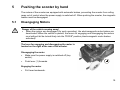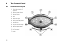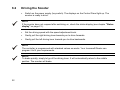
1
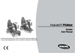
Invacare® Auriga
Scooter
User Manual
Invacare advises that you need to check the road and traffic laws
in your state regarding the use of scooters and power wheelchairs
This User Manual covers the 3
Auriga scooter models (maximum
speed of 6.4 km/h, 8 km/h and 10
km/h respectively). Some information
described in this User Manual are
specific to the 6.4 km/h model only.
How can you get in touch with Invacare®?
If you have any questions or need support, please contact your authorised Invacare® Dealer first. They have the
necessary know-how and equipment plus the special knowledge concerning your Invacare® product which
enables them to offer you all-round satisfactory service. Should you wish to contact us directly, you can reach
us at the following.
Invacare® Australia Pty Ltd
1 Lenton Place
North Rocks NSW 2151
Australia
Phone: +61 2 8839 5333
Fax:
+61 2 8839 5311
Phone Free: 1800 460 460
Email: [email protected]
2
Invacare®NewZealand
4 Westfield Place
Mt Wellington
New Zealand
Phone: +64 9 917 3939
Fax: +64 9 917 3957
Phone Free: 0508 468 2227
Email: [email protected]
Table of Contents
Chapter
1
Page
Introduction .....................................................................................7
1.1
1.2
2
Safety Notes.....................................................................................9
2.1
2.2
2.3
3
4
Before driving for the first time............................................................................................16
Taking Obstacles ................................................................................................................17
Driving up and down gradients ...........................................................................................18
Parking and Standstill .........................................................................................................18
Pushing the scooter by hand .......................................................19
5.1
6
General Safety Notes ...........................................................................................................9
Safety Information on Electromagnetic Interference ..........................................................12
Safety Information on Driving and Freewheel Mode ..........................................................13
The most important parts .............................................................15
Driving ............................................................................................16
4.1
4.2
4.3
4.4
5
Important symbols in this manual .........................................................................................8
Type Classification and Area of Use ....................................................................................8
Disengaging Motors............................................................................................................19
The Control Panel..........................................................................20
6.1 Control Panel layout ...........................................................................................................20
6.1.1 Seat Lifter "Up" and "Down" Buttons ...............................................................................21
6.1.2 Status display ..................................................................................................................21
6.1.3 Battery charge display .....................................................................................................21
6.2 Driving the Scooter .............................................................................................................22
6.3 Diagnostics and Trouble Shooting......................................................................................23
6.3.1 Diagnosing Faults ............................................................................................................24
4
6.3.2
7
Adjustment Options ......................................................................28
7.1
7.2
7.3
7.4
7.5
8
Flash Codes.....................................................................................................................25
Adjusting the angle of the backrest ....................................................................................28
Adjusting the position of the seat from front to back ..........................................................29
Adjusting the width of the armrests ....................................................................................30
Releasing the seat so that it may rotated and/or removed.................................................31
Adjusting the height of the seat ..........................................................................................32
Electrical System...........................................................................34
8.1 Electronics Protection System ............................................................................................34
8.1.1 The main fuse ..................................................................................................................35
8.2 Batteries..............................................................................................................................35
8.2.1 What you need to know about batteries ..........................................................................35
8.2.2 Charging the batteries .....................................................................................................37
8.2.3 Removing and fitting batteries .........................................................................................39
8.2.3.1 Removing the batteries.................................................................................................40
8.2.3.2 How to handle damaged batteries correctly .................................................................41
9
10
Care and maintenance ..................................................................42
Repair Instructions........................................................................44
10.1 Repairing a flat tyre...........................................................................................................44
10.1.1 Repairing a flat tyre (pneumatic tyres type 260 x 85)....................................................45
10.1.1.1 Removing a rear wheel...............................................................................................45
10.1.1.2 Removing a front wheel (4-Wheel Version)................................................................46
10.1.1.3 Removing a front wheel (3-Wheel Version)................................................................47
10.1.1.4 Repairing the flat tyre..................................................................................................48
11
Dismantling the scooter for transport .........................................50
11.1 Removing the seat............................................................................................................50
11.2 Removing the batteries and the Drive Unit.......................................................................51
11.2.1 Removing the batteries..................................................................................................51
11.2.2 Removing the Drive Unit................................................................................................52
5
11.2.3
12
13
6
Removing the Steering Column.....................................................................................53
Technical Specifications...............................................................54
Inspections Performed..................................................................57
1
Introduction
Dear User,
First of all we wish to thank you for your confidence in our products! We hope you will enjoy your
new Scooter.
This manual contains important hints and information on:
•
Safety
•
Operation
•
Care and maintenance.
Please familiarise yourself thoroughly before making your first trip.
Some of the necessary maintenance and adjustments can be carried out by the user. Some
adjustments, however, require technical training and are only allowed to be performed by your
Invacare® specialised dealer. Any damage or defects caused by non observance of the operating
instructions or by poor maintenance are excluded from liability.
The instructions contain information which is protected by copyright. They may not be reproduced
or copied in whole or in part without the prior written consent of Invacare® or its authorised
representative, Errors and modifications serving technological progress excepted.
7
1.1
Important symbols in this manual
WARNING: This symbol warns you of danger!
• Follow the instructions to avoid injury to the user or damage to the product!
NOTE:
This symbol indicates hints and suggestions which should help make operating the product
easier and point out special functions.
REQUIREMENTS:
• This symbol indicates a list of the different tools and other requirements you will need to do
certain maintenance work.
1.2
Type Classification and Area of Use
This vehicle has been classified as Mobility Product (for indoor and outdoor areas). It has
been successfully tested for its safety according to international standards.
8
2
Safety Notes
•
2.1
READ WELL BEFORE OPERATION!
General Safety Notes
Danger of injury if this scooter is used in any other way than the purpose described in this
manual!
• Adhere strictly to the instructions in this user's manual!
Danger of injury if the scooter is driven when your ability to drive is impaired by
medication or alcohol!
• Never drive any vehicle under the influence of medication or alcohol!
Danger of damage or injury if the scooter is accidentally set into motion!
• Switch the power system off before you get in, get out or handle unwieldy objects!
•
Be aware that there are only the motor brakes to stop your scooter. When the motors are
disengaged, these brakes are automatically deactivated. For this reason, freewheel operation
is only recommended on flat surfaces, never on gradients. Never leave your vehicle on a
gradient with its motors disengaged. Always re-engage the motors immediately after pushing
the vehicle.
9
Danger of injury if the On/Off Button is pressed while the vehicle is in motion, due to it
coming to an abrupt, sharp stop!
• If you have to brake in an emergency, simply release the drive lever, which will bring you to a
halt! Only switch the vehicle off while in motion as a last resort!
Danger of injury if the scooter is transported in another vehicle with the occupant seated
in it!
• Never transport the scooter with the occupant seated in it!
Danger of injury if maximum permissible load is exceeded!
• Do not exceed the maximum permissible load (see technical specifications)!
Danger of injury due to wrong lifting or dropping of heavy components!
• When maintaining, servicing or lifting any part of your scooter, take into account the weight of
the individual components, especially of the batteries! Be sure at all times to adopt the correct
lifting posture and ask for assistance if necessary!
Danger of injury if you fall off of the scooter!
• If restraining systems are installed (such as seat belts), use them each time you drive the
scooter.
10
Danger of injury by moving parts!
• Make sure that no injury is incurred by moving parts of the scooter, like wheels or a Seat
Lifter, especially when children are around!
Danger of fire or breaking down due to electric devices being connected!
• Do not connect any electric devices to your vehicle that are not expressly certified by
Invacare® for this purpose! Have all electrical installations done by your authorised
Invacare® Dealer!
Danger of technical failure and injury if unauthorized spare parts and components are
used!
• Only use original Invacare® spare parts, which have been approved for use with this vehicle!
11
2.2
Safety Information on Electromagnetic Interference
This electric vehicle was successfully tested in accordance with international standards as to its
compliance with Electromagnetic Interference (EMI) Regulations. However, electromagnetic fields,
such as those generated by radio and television transmitters, and cellular phones, can influence
the functions of electric vehicles. Also, the electronics used in our vehicles can generate a low level
of electromagnetic interference, which however will remain within the tolerance permitted by law.
For these reasons we ask you to please observe the following precautions:
WARNING: Danger of malfunction due to electromagnetic interference!
• Do not switch on or operate portable transceivers or communication devices (such as radio
transceivers or mobile phones) when the vehicle is switched on!
12
•
Avoid getting near strong radio and television transmitters!
•
In case the vehicle should be set in motion unintentionally or the brakes are released, switch
it off immediately!
•
Adding electrical accessories and other components or modifying the vehicle in any way can
make it susceptible to electromagnetic interference. Keep in mind that there is no sure way to
determine the effect such modifications will have on the overall immunity of the electronic
system!
•
Report all occurrences of unintentional movement of the vehicle, or release of the electric
brakes to the manufacturer!
2.3
Safety Information on Driving and Freewheel Mode
Danger of injury if the vehicle tips over!
• Only ever negotiate gradients of up to the maximum defined in the Technical Specifications
and only with the backrest in an upright position, and the seat lifter in the lowest position (if
installed)!
•
Only ever drive downhill at a maximum of 2/3 of the top speed! Avoid abrupt braking or
accelerating on gradients!
•
If at all possible, avoid driving on slippery surfaces (such as snow, gravel, ice etc.) where
there is a danger of you losing control over the vehicle, especially on a gradient! If driving on
such a surface is inevitable, then always drive slowly and with the utmost caution!
•
Never attempt to overcome an obstacle when on an uphill or downhill gradient!
•
Never attempt to drive up or down a flight of steps!
•
Always approach obstacles straight on! Ensure that the front wheels and rear wheels move
over the obstacle in one stroke, do not stop halfway! Do not exceed the maximum obstacle
height (see Technical Specifications)!
•
Avoid shifting your centre of gravity as well as abrupt changes of direction when the vehicle is
in motion!
13
Danger of injury if the vehicle tips over! (Continued)
• Never use the vehicle to transport more than one person!
•
Do not exceed the maximum permissible load!
•
When loading the vehicle, always distribute the weight evenly! Always try to keep the centre
of gravity of the vehicle in the middle, and as close to the ground as possible!
•
Note that the vehicle will brake or accelerate if you change the Driving Speed while it is in
motion!
Danger of injury if you collide with an obstacle when driving through narrow passages
such as doorways and entrances!
• Drive through narrow passages in the lowest Driving Speed and with due caution!
14
3
The most important parts
1) De-clutching lever
2) Release lever for swivelling and
removing seat (under the seat on
the right)
3) Release lever for seat sliding rail
adjustment (under the seat on the
right in the front)
4) Primary Charging Socket
5) Key switch (ON/OFF)
6) Throttle
7) Control panel
8) Lever for adjusting the angle of the
steering column
15
4
Driving
4.1
Before driving for the first time...
Before you take your first trip, you should familiarise yourself well with the operation of the vehicle
and with all operating elements. Take your time to test all functions and driving modes.
NOTE:
If installed, use the restraining systems (seat belts) each time you use the vehicle.
Sitting Comfortably = Driving Safely
Before each trip, make sure that:
16
•
You are within easy reach of all operating elements.
•
The battery charge is sufficient for the distance intended to be covered.
•
The seatbelt is in perfect order.
4.2
Taking Obstacles
Your Invacare® Auriga can overcome obstacles and kerbs of up to 8 cm.
CAUTION: Danger of Tipping Over!
• Never approach obstacles at an angle!
•
Put your backrest into an upright position before climbing an obstacle!
Driving up over an obstacle
•
Correct
Approach the kerb or obstacle slowly head-on. Shortly
before the front wheels touch the obstacle, increase the
speed and reduce only after the rear wheels have also
climbed the obstacle.
Driving down off of an obstacle
•
Approach the kerb or obstacle slowly head-on. Before the
front wheels touch the obstacle, reduce speed and keep it
until also the rear wheels have come down off of the
obstacle.
Incorrect
17
4.3
Driving up and down gradients
The Invacare® Auriga can safely climb the following gradients:
• 4-Wheel Version (up to 150 kg payload):
12°
• 3-Wheel Version (up to 120 kg payload):
12°
• 3-Wheel Version (up to 150 kg payload):
10°
WARNING: Danger of tipping over!
• Only ever drive downhill at a maximum of 2/3 of the top speed!
4.4
•
Always return the backrest of your seat to an upright position before ascending slopes! We
recommend that you lean the backrest slightly to the rear before descending slopes!
•
Never attempt to ascend or descend a slope on slippery surfaces or where there is a danger
of skidding (such as wet pavement, ice etc)!
•
Avoid trying to get out of the vehicle on an incline or a gradient!
•
Always drive straight in the direction the road or path you are on goes, rather than attempting
to zigzag!
•
Never attempt to turn around on an incline or a slope!
Parking and Standstill
When parking your vehicle or if your vehicle is stationary for a prolonged period:
•
18
Switch the vehicle's power system off (key switch).
5
Pushing the scooter by hand
The motors of the scooter are equipped with automatic brakes, preventing the scooter from rolling
away out of control when the power supply is switched off. When pushing the scooter, the magnetic
brakes must be disengaged.
5.1
Disengaging Motors
Danger of the vehicle running away!
• When the motors are disengaged (for push operation), the electromagnetic motor brakes are
deactivated! When the vehicle is parked, the levers for engaging and disengaging the motors
must without fail be locked firmly into the "DRIVE" position (electromagnetic motor brakes
activated)!
The lever for engaging and disengaging the motor is
located on the right at the rear of the scooter.
Disengaging the motor
•
Make sure the power supply is switched off (key
switch).
•
Push lever (1) forwards.
Engaging the motor
•
Pull lever backwards.
19
6
The Control Panel
6.1
Control Panel layout
1)
Seat Lifter activation (if
installed)
2)
Battery charge indicator
3)
Hazard flashers
4)
Horn
5)
Right turn signal
6)
Driving speed adjustment
7)
Throttle lever
8)
Plug for external charger
9)
Reduced Speed Mode
10) Left turn signal
11) Lights
20
6.1.1
Seat Lifter "Up" and "Down" Buttons
•
Press the button to activate the Seat Lifter (if is installed).
•
Raise or lower the seat using the throttle lever.
NOTE
If the Seat Lifter is not lowered entirely, then the speed of the scooter is automatically reduced to
lower the risk of tipping over. This is indicated by the LED just above the buttons being lit. Lower
the Lifter to restore speed to it's normal level. The LED will go out.
6.1.2
Status display
NOTE
The leftmost diode of the battery charge display serves as an error message display (status
display). For an explanation of the Error Codes please see chapter 6.3 on page 23.
6.1.3
Battery charge display
•
•
•
All diodes lit: full driving range
Only red and yellow diodes lit: decreased drive range. Charge batteries at end of journey.
Only red diodes lit / flashing: battery reserve = very low drive range!
Charge batteries immediately!
NOTE
Total discharge protection: After a certain drive time on reserve battery power the electronics
switches the drive off automatically and the scooter will be immobile.
21
6.2
Driving the Scooter
•
Switch on the power supply (key switch). The displays on the Control Panel light up. The
scooter is ready to drive.
NOTE
If the scooter does not respond after switching on, check the status display (see chapter "Status
display" on page 21.).
•
Set the driving speed with the speed adjustment knob.
•
Gently pull the right driving lever towards you to drive forwards.
•
Gently pull the left driving lever towards you to drive backwards.
NOTE
The controller is programmed with standard values ex-works. Your Invacare® Dealer can
program it to fit your requirements.
NOTE:
To brake quickly, simply let go of the driving lever. It will automatically return to the middle
position. The scooter will brake.
22
6.3
Diagnostics and Trouble Shooting
The electronics system provides diagnostics information to assist technicians to diagnose and
correct faults within the scooter system. The existence of a fault will cause the status light to flash
in bursts, separated by a pause. The nature of the fault is indicated by the number of flashes in
each burst, also referred to as the Flash Code.
Depending on the severity of the fault and impact on user safety, the electronic system will react
differently. It may…
•
•
•
Simply display the Flash Code as a warning and allow normal driving and operation.
Display the Flash Code, stop the scooter and prevent driving until the electronic system
has been turned off and then back on again.
Display the Flash Code, stop the scooter and prevent driving until the fault has been fixed.
For detailed descriptions of what each Flash Code means, and the probable cause and remedy,
see Section 6.3.2 on page 25.
23
6.3.1
Diagnosing Faults
Use the following troubleshooting guide if the scooter fails to operate.
NOTE
Turn the key switch on before beginning any diagnostics.
If the Status Light is OFF
Check that the key switch is turned ON.
Check that all cables are connected correctly.
If only the leftmost diode of the battery charge display is PERMANENTLY ON
Contact your authorised Invacare® Dealer
If the leftmost diode of the battery charge display is FLASHING
Count the number of flashes and refer to the next section.
24
6.3.2
Flash Codes
Number of
flashes
1
2
Fault
Impact on
Scooter
Will drive
Battery needs
charging
Battery voltage Drive inhibited
too low
Notes
•
•
•
Lifter raised
3
Driving speed
reduced
Battery voltage Drive inhibited
too high
•
•
•
Battery charge is running low. Recharge
the batteries as soon as possible.
Battery charge is empty. Recharge the
batteries.
If the scooter is left off for a few minutes,
battery charge may recover sufficiently to
allow driving for a short period of time.
Lower lifter completely.
Battery charge is too high. If a charger is
plugged in, unplug it.
The electronic system charges the
batteries when travelling down slopes or
decelerating. Excessive charging in this
manner may cause this fault. Turn the
scooter power off and then back on
again.
25
Number of
flashes
4
Fault
Current Limit
Time Out
Impact on
Scooter
Drive inhibited
Notes
•
•
5
Brake Fault
Drive inhibited
•
•
6
Out Of Neutral Drive inhibited
At Power Up
•
•
26
The scooter has drawn too much current
for too long, possibly because the motor
has been over-worked, jammed or
stalled. Turn the scooter power off, leave
it off for a few minutes, and then turn the
power back on again.
The controller has detected a shortcircuited motor. Check the cable harness
for short and check the motor: Contact
your authorised Invacare® Dealer.
Check that the declutching lever is in the
engaged position.
The park brake coil or wiring is faulty.
Check the park brake and wiring for open
or short circuits. Contact your authorised
Invacare® Dealer.
Throttle is not in neutral position when
turning key switch on. Return throttle to
neutral, turn power off, and back on
again.
Throttle may need to be re-calibrated.
Contact your authorised Invacare®
Dealer.
Number of
flashes
7
8
9
Fault
Speed Pot
Error
Motor Volts
Error
Other Internal
Errors
Impact on
Scooter
Drive inhibited
Notes
•
Drive inhibited
•
Drive inhibited
•
The throttle or its wiring may be faulty or
incorrectly set up. Contact your
authorised Invacare® Dealer.
The motor or its wiring is faulty. Contact
your authorised Invacare® Dealer.
Contact your authorised Invacare®
Dealer.
27
7
Adjustment Options
7.1
Adjusting the angle of the backrest
The backrest is held in place by a metal plate on each side. Each plate has 4 holes that are used to
set the backrest to different angles. This is done by selecting different combinations of holes.
Requirements:
• Allen key, 4 mm
•
28
Spanner, 10 mm
•
Remove the screws on both sides of the seat
that hold the backrest (1), using the spanner
and Allen key.
•
Adjust the backrest to the desired angle.
•
Reposition the screws and tighten.
7.2
Adjusting the position of the seat from front to back
The lever for adjusting the seat back and forth is
located under the seat in the front on the right
side.
•
Pull the lever (1) to release the seat.
•
Slide the seat forward or backward to the
desired position.
•
Release the lever to lock the seat in place.
29
7.3
Adjusting the width of the armrests
The knobs to release the armrests are located in the back, under the seat (1).
30
•
Turn the knobs to release the armrests.
•
Adjust the armrests to the desired width.
•
Retighten the knobs.
7.4
Releasing the seat so that it may rotated and/or removed
The seat can be rotated to the side to ease getting
on and off of the scooter. In this position, the seat
can also be removed.
The lever for releasing the seat so that it can be
rotated is located under the seat on the right (1).
•
Push the lever forward to release the seat.
•
Rotate the seat to the side.
•
If desired, firmly grip the seat by the backrest
and the front edge and pull upwards to
remove it.
31
7.5
Adjusting the height of the seat
The height of the seat can be adjusted to 43, 45, 47, or 49 cm.
Requirements:
• 2 Spanners, 17 mm
32
•
Remove the seat
•
Remove the cover from the battery and motor
compartment.
•
Remove the bolt that hold the seat post, using the two
spanners.
NOTE
Do not use the uppermost hole. In this position the seat is too low, and does not have enough
clearance above the cowling.
•
Adjust the seat height.
•
Reposition the bolt and tighten.
33
8
Electrical System
8.1
Electronics Protection System
The vehicle's electronics are equipped with an overload-protection system.
If the motors are put under considerable strain for a longer period of time (for example, when
driving up a steep hill) and especially when the ambient temperature is high, then the electronic
system could overheat. In this case the vehicle's power is reduced gradually until it finally comes to
a halt. The Status Display shows a corresponding error code. By switching the power supply off
and back on again, the error code is cancelled and the electronics are switched back on. It will take
approximately five minutes until the electronics have cooled down enough that the motors deliver
their full power again.
When the motors are stalled by an insurmountable obstacle, such as a high kerb, and the vehicle
driver allows the motors to strain against this hindrance for more than 20 seconds without moving,
then the electronics will automatically switch off to prevent the motors from being damaged. The
Status Display shows a corresponding error code. By switching off and back on again, the error
code is cancelled and the electronics are switched back on.
34
8.1.1
The main fuse
The entire electric system is protected against overload by two master fuses. The master fuses are
mounted on the positive battery cables. They can be replaced only after removing the battery lid.
NOTE
A defective main fuse may be replaced only after checking the entire electric system. An
Invacare® specialised dealer must perform the replacement.
8.2
Batteries
8.2.1
What you need to know about batteries
Power is supplied by two 12V gel batteries. The batteries are maintenance-free and only need
regular charging.
New batteries should always be once fully charged before their first use. New batteries will be at
their full capacity after having run through approx. 10 - 20 charging cycles. How fast the batteries
will be discharged will depend on many circumstances, such as ambient temperature, condition of
the surface of the road, tyre pressure, weight of the driver, way of driving and utilisation of lighting,
etc.
35
NOTE:
Pay attention to the Battery Charge Indicator! Make sure to charge the batteries when the
Battery Charge Indicator shows that battery charge is low. We recommend charging the batteries
after each trip, as well as each night over night. Depending on the level of discharge, it can take
up to 12 hours until the batteries are fully charged again.
Protect your charger for sources of heat such as heaters and direct sunlight. If the battery
charger overheats, charging current will be reduced and the charging process delayed.
To avoid damaging the batteries, never allow them to be fully discharged. Do not drive on heavily
discharged batteries if it is not absolutely necessary, as this will strain the batteries unduly and
greatly shorten their life expectancy.
In case your vehicle is not used for a longer period of time, then the batteries must be charged at
least once a month to maintain a full charge. Alternatively, the vehicle can stay connected to the
charger. The batteries cannot be overcharged with the specified charger.
Please use only charging devices in Class 2. This class of chargers may be left unattended
during charging. All charging devices which are supplied by Invacare®comply with these
requirements.
36
8.2.2
Charging the batteries
Note
The Invacare® Auriga can be charged using an external charger.
•
Make sure you read and understand the battery charger's User's Manual, as well as the
safety not es on the front and rear panels of the charger!
WARNING:
Danger of explosion and destruction of batteries if the wrong battery charger is used!
Only ever use the external battery charger supplied by Invacare® , or a charger that has been
•
approved by Invacare®!
Danger of electric shock and damage to the battery charger if it is allowed to get wet!
•
Protect the battery charger from water!
Danger of short circuit and electric shock if the battery charger has been damaged!
•
Do not use the battery charger it has fallen on the ground or been damaged!
Danger of fire and electric shock if a damaged extension cable is used!
•
Only ever use an extension cable if it is absolutely necessary! In case you must use one,
make sure it is in good condition!
37
Connecting the charger
•
First connect the battery charger to the
scooter. (Charging socket on rear edge of control panel)
•
Then connect the battery charger to the mains
power supply and switch on.
Disconnecting the charger
•
First disconnect the battery charger from the
mains power supply.
•
Then disconnect the battery charger from the
scooter.
How can I tell when the batteries are fully charged?
Look through the slot for the de-clutching lever (2) down into the motor and battery compartment.
You will see a green LED. This is the charger LED.
LED ACTIVITY
LED lights contantly
LED dims and flickers
LED go out / flickers for a few seconds /
goes out again
38
CHARGING PHASE
Start
90% Finished
Finished
8.2.3
Removing and fitting batteries
WARNING:
Danger of injury if the batteries are not handled correctly during assembly and
maintenance work!
• New batteries should be installed by authorised technicians!
•
Observe the warnings on the batteries!
•
Take into account the heavy weight of the batteries!
•
Only ever use the battery type defined in the technical specifications!
Danger of fire and burns if battery terminals are short-circuited!
• DO NOT short-circuit battery terminals with a tool!
WARNING:
Corrosion and burns from acid leakage if batteries are damaged!
• Remove clothes that have been soiled by acid immediately!
After contact with skin:
• Immediately wash affected area with lots of water!
After contact with eyes:
• Immediately rinse eyes under running water for several minutes; consult a physician!
39
8.2.3.1
Removing the batteries
Requirements:
• Wrench 11 mm
•
Remove the seat.
•
Remove the battery and motor compartment cover.
•
Disconnect the main cable harness.
•
Open the belts that hold the batteries in place (1).
•
Loosen battery clamp of the blue cable at the negative pole
of the battery with the wrench and remove cable.
•
Loosen the battery clamp of the red cable at the positive
pole of the battery with the wrench and remove cable.
•
Repeat procedure on the other side.
NOTE
Fitting of new batteries is done in reverse order.
40
8.2.3.2
How to handle damaged batteries correctly
WARNING:
Corrosion and burns from acid leakage if batteries are damaged!
• Remove clothes that have been soiled by acid immediately!
After contact with skin:
• Immediately wash affected area with lots of water!
After contact with eyes:
• Immediately rinse eyes under running water for several minutes; consult a physician!
Requirements:
• Safety goggles
•
Acid-resistant gloves
•
Acid-resistant receptacle for transportation
•
Always wear appropriate safety clothing when handling damaged batteries.
•
Place damaged batteries in an acid-resistant receptacle immediately after removing them.
•
Only ever transport damaged batteries in an appropriate acid-resistant receptacle.
•
Wash all objects that have come into contact with acid with lots of water.
Disposing of dead or damaged batteries correctly
Dead or damaged batteries can be given back to your dealer or directly to Invacare®.
41
9
Care and maintenance
NOTE:
Have your vehicle checked once a year by an authorised Invacare® dealer in order to maintain
it's driving safety.
Cleaning the vehicle
When cleaning the vehicle, pay attention to the following points:
42
•
Only use a damp cloth and gentle detergent.
•
Do not use any scrubbing agents.
•
Do not subject the electronic components to any direct contact with water.
•
Do not use high-pressure cleaning devices.
Monthly
Weekly
When
Delivered
Maintenance Jobs
Seat and backrest padding:
- Check for perfect condition.
Tyres:
- Have tyres checked for specified air pressure (2,5 bar).
Front wheels
- Front wheels must spin smoothly.
- If wheels wobble or do not spin easily, adjust steering pivot pin or front
wheel bearing.
Rear wheels:
- Test wheel for firm seat on the axle drive shaft.
- Rear wheels must spin without wobbling
Electronics / Electrical System:
- Check all plug connections for condition and firm connection.
- Have batteries been fully charged before the daily operation?
- Are all holders, screws firmly fixed, tight and safe?
- Are all electric bulbs of the lighting system (if applicable) in working order?
Cleaning:
- Clean all parts carefully.
Before every trip
Before each trip
When necessary
Once a year you should have your vehicle inspected and serviced by your authorised
dealer. A complete checklist of necessary maintenance work can be found in the Service
Manual, which can be obtained from Invacare®.
43
10
Repair Instructions
The following are instructions on repairs that can be performed by the user. For the specifications
of spare parts please see "Technical Specifications" on page 55, or consult the Service Manual,
available from Invacare®. In case you require assistance, please contact your Invacare® Dealer.
10.1
Repairing a flat tyre
WARNING: Danger of damage or injury if the vehicle is accidentally set into motion during
repairs!
• Switch the power off (ON/OFF Button)!
44
•
Engage the motors!
•
Secure the vehicle against rolling away by placing wedges under the wheels!
10.1.1 Repairing a flat tyre (pneumatic tyres type 260 x 85)
10.1.1.1 Removing a rear wheel
Requirements:
• Spanner 19 mm
•
Rubber hammer
•
Jack the vehicle up and place a block of wood underneath it
to prop it up.
•
Remove the nut that secures the wheel (1) using the 19 mm
spanner.
•
Remove the wheel, using the rubber hammer to coax it off of
the axle by gently hitting it on the rear side.
Having trouble removing the wheel?
You might need to use a special tool. Please ask your authorized Invacare® Dealer for
assistance.
Re-assembly
Re-assembly is done in reverse order. Make sure that the wheel is put back on the same side it
was on, and that it runs in the same direction it did before it was removed.
45
10.1.1.2 Removing a front wheel (4-Wheel Version)
Requirements:
• Allen key 6 mm
•
Rubber hammer
•
Jack the vehicle up and place a block of wood underneath it
to prop it up.
•
Remove the nut that secures the wheel (1) using the 6 mm
Allen key.
•
Remove the wheel, using the rubber hammer to coax it off of
the axle by gently hitting it on the rear side.
Re-assembly
Re-assembly is done in reverse order. Make sure that the wheel is put back on the same side it
was on, and that it runs in the same direction it did before it was removed.
46
10.1.1.3 Removing a front wheel (3-Wheel Version)
Requirements:
• 2 Spanners, 17 mm
•
Tilt the scooter over on it's side.
•
Remove the bolts that hold the wheel (1) using the two
spanners, then remove the wheel from the fork.
Re-assembly
Re-assembly is done in reverse order. Make sure that the wheel runs in the same direction it did
before it was removed.
47
10.1.1.4 Repairing the flat tyre
Requirements (General)
• Repair kit for inner tubes or an new inner tube.
•
Talcum powder
•
Socket spanner, 13 mm
Requirements (3-Wheel Version - front wheel):
• Allen key, 6 mm
48
•
Remove the valve cap.
•
Let the air out of the tyre by pressing the pin in the
centre of the valve in.
•
Remove the 4 nuts (1) from the rear of the wheel
using the 13 mm spanner (3-Wheel Version - front
wheel: counter the bolts from the other side using
the 6 mm Allen key).
•
Remove the rim halves from the tyre and take out
the inner tube.
•
Repair the inner tube and re-fit, or replace it with a
new one.
Did the old inner tube get wet during repair?
In case the old inner tube is to be repaired and used again, and it gets wet during repair, then it
is easier to re-fit it if you powder it lightly with talcum powder.
•
Place the rim halves in the tyre from the outside.
•
Pump up the tyre a little.
•
Re-position the screws and nuts that hold the rim together and tighten them firmly.
•
Check to make sure that the tyre is squarely in place on the rim.
•
Pump up the tyre to the recommended tyre pressure (3.5 bar, or 50 psi).
•
Check to make sure that the tyre is still squarely and snugly in place on the rim.
•
Screw the valve cap back on.
•
Refit the wheel.
49
11
Dismantling the scooter for transport
To dismantle the scooter for transport, proceed as follows:
•
Remove the seat
•
Remove the batteries
•
Remove the drive unit
•
Remove the steering column
The scooter is re-assembled in reverse order.
11.1
Removing the seat
The lever for releasing the seat so that it can be
rotated and removed is located under the seat on
the right (1).
50
•
Push the lever forward to release the seat.
•
Rotate the seat to the side.
•
Firmly grip the seat by the backrest and the
front edge and pull upwards to remove it.
11.2
Removing the batteries and the Drive Unit
•
After removing the seat, proceed to remove the cover from the battery and motor compartment
Cover. It is held in place with Velcro strips, so you only need to pull it upwards to remove it.
11.2.1 Removing the batteries
For instructions on how to remove the batteries see chapter "Removing and fitting batteries" on
page 40.
51
11.2.2 Removing the Drive Unit
WARNING: Danger of injury by moving parts!
• The release lever for the drive unit is under tension! When releasing the drive unit be very
careful not to get your hands or feet caught underneath the chassis of the scooter, or in
between any moving parts!
To release the drive unit, first you need to remove the
securing pin that prevents the release lever from opening
accidentally.
52
•
Remove the pin (1) that secures the latching
mechanism.
•
Release the drive Unit by pressing the Release Lever
(2) forward and downward.
11.2.3 Removing the Steering Column
•
Fold up the rubber sleeve that protects the joint (A).
•
Loosen and disconnect the cable (1).
•
Loosen and remove the bolt (clamping lever) that holds the
steering column in place.
Re-assembly
Re-assembly is done in reverse order.
53
12
Technical Specifications
3-Wheel Version
Electrical
System
Motor
Batteries
•
•
•
Main battery fuse •
Charger
•
Weight
Empty weight
(including 30 Ah
batteries)
Weight of the
heaviest part
Maximum load
(payload)
54
230 W
Standard: 2 x 30 AH
Option: 2 x 40 AH
30 A
Off board, Output 8 A,
24V DC for 30/40 Ah batteries
(external battery charger plug
on rear of control panel)
4-Wheel Version
•
•
•
•
•
230 W
Standard: 2 x 30 AH
Option: 2 x 40 AH
30 A
Off board, Output 8 A,
24V DC for 30/40 Ah batteries
(external battery charger plug
on rear of control panel)
• 88 kg*
• 94 kg*
• 21.4 kg
• 25 kg
• 150 kg
• 150 kg
Dimensions
Height
Width
Length (w/o bumpers and
anti-tippers)
Seat height (measured
from the chassis, manually
adjustable)
Backrest height (w/o
headrest)
Backrest height (with
headrest)
Backrest angle (manually
adjustable)
Seat width
Seat depth
Armrest height
Tyres
Tyre pressure if fitted with
pneumatic tyres
3-Wheel Version
4-Wheel Version
• 120 cm*
• 61 cm*
• 120 cm*
• 120 cm*
• 61 cm*
• 122 cm*
• 43, 45, 47, 49 cm*
• 43, 45, 47, 49 cm*
• 44 cm*
• 44 cm*
• 63 cm*
• 63 cm*
• 0°, 10°, 15°, 30°
• 0°, 10°, 15°, 30°
• 44-55 cm*
• 44 cm*
• 20-26 cm*
• 44-55 cm*
• 44 cm*
• 20-26 cm*
• 2.5 bar (40 psi)
• 2.5 bar (40 psi)
55
Driving attributes
Speed
Safe climbing capability
Maximum obstacle height
Minimum turning radius
Range according to ISO
7176 **
With 30 Ah Batteries:
With 40 Ah Batteries:
3-Wheel Version
4-Wheel Version
• 6.4 km/h (4 mph)
• up to 120 kg load: 12°
(21%)
• up to 150 kg load: 10°
(17%)
• 8 cm
• 120 cm
• 6.4 km/h (4 mph)
• 12° (21%)
• 32 km (20 miles)
• 40 km (25 miles)
• 32 km (20 miles)
• 40 km (25 miles)
• 8 cm
• 150 cm
8 km/h and 10 km/h maximum speed Auriga models also available.
This User Manual covers the 3 Auriga scooter models (maximum speed of 6.4 km/h, 8 km/h and
10 km/h respectively). Some information described in this User Manual are specific to the 6.4 km/h
model only.
* Approximately.
** Note: The scooter's range depends strongly on various factors, such battery charge, ambient temperature, local topography, road conditions, tyre pressure, driver's
weight, driving habits and the usage the batteries for lighting, actuators, and so on.
56
13
Inspections Performed
It is confirmed by stamp and signature that all jobs listed in the inspection schedule of the Service
and Repair Instructions have been properly performed. The list of the inspection jobs to be
performed can be found in the Service Manual which is available through Invacare®.
Delivery Inspection
1st Annual Inspection
Stamp of authorised Dealer / Date / Signature
Stamp of authorised Dealer / Date / Signature
2nd Annual Inspection
3rd Annual Inspection
Stamp of authorised Dealer / Date / Signature
Stamp of authorised Dealer / Date / Signature
4th Annual Inspection
5th Annual Inspection
Stamp of authorised Dealer / Date / Signature
Stamp of authorised Dealer / Date / Signature
57
LIMITED WARRANTY
PLEASE NOTE: THE WARRANTY BELOW HAS BEEN DRAFTED TO COMPLY WITH
FEDERAL LAW APPLICABLE TO PRODUCTS MANUFACTURED AFTER JULY 4, 1975.
This warranty is extended only to the original purchaser/user of our products.
This warranty gives you specific legal rights and you may also have other legal rights which
vary from state to state.
Invacare warrants this product to be free from defects in materials and workmanship for a
period of eighteen (18) months on electrical and transaxle and three (3) years on frame from
date of purchase. If within such warranty period any such product shall be proven to be
defective, such product shall be repaired or replaced at Invacare's option. This warranty
does not include any labor or shipping charges incurred in replacement part installation or
repair of any such product. Invacare’s sole obligation and your exclusive remedy under this
warranty shall be limited to such repair and/or replacement.
For warranty service, please contact the dealer from whom you purchased your Invacare
product. In the event you do not receive satisfactory warranty service, please write directly
to Invacare at the address on the back cover, provide dealer’s name, address, date of
purchase, indicate nature of the defect and, if the product is serialized, indicate the serial
number. Do not return products to our factory without our prior consent.
LIMITATIONS AND EXCLUSIONS: THE FOREGOING WARRANTY SHALL NOT APPLY TO
SERIAL NUMBERED PRODUCTS IF THE SERIAL NUMBER HAS BEEN REMOVED OR
DEFACED, PRODUCTS SUBJECTED TO NEGLIGENCE, ACCIDENT, IMPROPER OPERATION,
MAINTENANCE OR STORAGE, PRODUCTS MODIFIED WITHOUT INVACARE’S EXPRESS
WRITTEN CONSENT (INCLUDING, BUT NOT LIMITED TO, MODIFICATION THROUGH THE
USE OF UNAUTHORIZED PARTS OR ATTACHMENTS; PRODUCTS DAMAGED BY REASON
OF REPAIRS MADE TO ANY COMPONENT WITHOUT THE SPECIFIC CONSENT OF
INVACARE, OR TO A PRODUCT DAMAGED BY CIRCUMSTANCES BEYOND INVACARE’S
CONTROL, AND SUCH EVALUATION WILL BE SOLELY DETERMINED BY INVACARE. THE
WARRANTY SHALL NOT APPLY TO PROBLEMS ARISING FROM NORMAL WEAR OR
FAILURE TO ADHERE TO THESE INSTRUCTIONS.
THE FOREGOING WARRANTY IS EXCLUSIVE AND IN LIEU OF ALL OTHER EXPRESS
WARRANTIES. IMPLIED WARRANTIES, IF ANY, INCLUDING THE IMPLIED WARRANTIES OF
MERCHANTABILITY AND FITNESS FOR A PARTICULAR PURPOSE, SHALL NOT EXTEND
BEYOND THE DURATION OF THE EXPRESS WARRANTY PROVIDED HEREIN AND THE
REMEDY FOR VIOLATIONS OF ANY IMPLIED WARRANTY SHALL BE LIMITED TO REPAIR
OR REPLACEMENT OF THE DEFECTIVE PRODUCT PURSUANT TO THE TERMS
CONTAINED HEREIN. INVACARE SHALL NOT BE LIABLE FOR ANY CONSEQUENTIAL OR
INCIDENTAL DAMAGES WHATSOEVER.
THIS WARRANTY SHALL BE EXTENDED TO COMPLY WITH STATE/PROVINCIAL LAWS AND
REQUIREMENTS.
Invacare Australia Pty Ltd
Invacare Australia
1 Lenton Place
North Rocks NSW 2151
Australia
Phone 1800 460 460
Fax: (02) 8839 5311
Form No. 99-154
www.invacare.com.au
All rights reserved. All trademarks are owned by
or licensed to Invacare Corporation unless
otherwise noted. Teflon is a registered trademark
of E.I. DU Pont Nemours and Company.
Specifications and prices are subject to change
without notification. ©2008 Invacare Corporation
Part No. 1090132
Rev E (2) 08/09