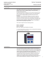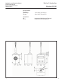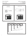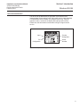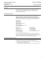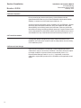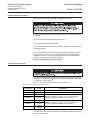
1
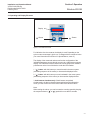
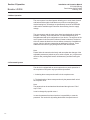
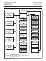
Installation and Operation Manual
X-PR-LR-056-PD-eng
Part Number: 541B171AAG
February, 2012
Brooks® LR-056
Brooks® LR-056
Pressure Transducer Display
Accurate, Miniature Plug-In Displays for
Point-of-Use Pressure Monitoring
LR-056 Pressure Transducer Display
Installation and Operation Manual
X-PR-LR-056-PD-eng
Part Number: 541B171AAG
February, 2012
Brooks® LR-056
Essential Instructions
Read before proceeding!
Brooks Instrument designs, manufactures and tests its products to meet many national and international standards. These products must be properly
installed, operated and maintained to ensure they continue to operate within their normal specifications. The following instructions must be adhered to and
integrated into your safety program when installing, operating and maintaining Brooks Instrument products.
• To ensure proper performance, use qualified personnel to install, operate, update, program and maintain the product.
• Read all instructions prior to installing, operating and servicing the product. If this instruction manual is not the correct manual, please see back cover for
local sales office contact information. Save this instruction manual for future reference.
WARNING: Do not operate this instrument in excess of the specifications listed in the Instruction and Operation Manual. Failure to heed this warning can result in
serious personal injury and / or damage to the equipment.
• If you do not understand any of the instructions, contact your Brooks Instrument representative for clarification.
• Follow all warnings, cautions and instructions marked on and supplied with the product.
• Install your equipment as specified in the installation instructions of the appropriate instruction manual and per applicable local and national codes.
Connect all products to the proper electrical and pressure sources.
• Operation: (1) Slowly initiate flow into the system. Open process valves slowly to avoid flow surges. (2) Check for leaks around the flow meter inlet and
outlet connections. If no leaks are present, bring the system up to the operating pressure.
• Please make sure that the process line pressure is removed prior to service. When replacement parts are required, ensure that qualified people use
replacement parts specified by Brooks Instrument. Unauthorized parts and procedures can affect the product's performance and place the safe operation
of your process at risk. Look-alike substitutions may result in fire, electrical hazards or improper operation.
• Ensure that all equipment doors are closed and protective covers are in place to prevent electrical shock and personal injury, except when maintenance is
being performed by qualified persons.
WARNING: For liquid flow devices, if the inlet and outlet valves adjacent to the devices are to be closed for any reason, the devices must be completely drained.
Failure to do so may result in thermal expansion of the liquid that can rupture the device and may cause personal injury.
European Pressure Equipment Directive (PED)
All pressure equipment with an internal pressure greater than 0.5 bar (g) and a size larger than 25mm or 1" (inch) falls under the Pressure Equipment Directive (PED).
• The Specifications Section of this manual contains instructions related to the PED directive.
• Meters described in this manual are in compliance with EN directive 97/23/EC.
• All Brooks Instrument Flowmeters fall under fluid group 1.
• Meters larger than 25mm or 1" (inch) are in compliance with PED category I, II or III.
• Meters of 25mm or 1" (inch) or smaller are Sound Engineering Practice (SEP).
European Electromagnetic Compatibility (EMC)
The Brooks Instrument (electric/electronic) equipment bearing the CE mark has been successfully tested to the regulations of the Electro Magnetic
Compatibility (2004/108/EC (EMC directive 89/336/EEC)).
Special attention however is required when selecting the signal cable to be used with CE marked equipment.
Quality of the signal cable, cable glands and connectors:
Brooks Instrument supplies high quality cable(s) which meets the specifications for CE certification.
If you provide your own signal cable you should use a cable which is overall completely screened with a 100% shield.
“D” or “Circular” type connectors used should be shielded with a metal shield. If applicable, metal cable glands must be used providing cable screen
clamping.
The cable screen should be connected to the metal shell or gland and shielded at both ends over 360 Degrees.
The shield should be terminated to an earth ground.
Card Edge Connectors are standard non-metallic. The cables used must be screened with 100% shield to comply with CE certification.
The shield should be terminated to an earth ground.
For pin configuration : Please refer to the enclosed Instruction Manual.
ESD (Electrostatic Discharge)
CAUTION: This instrument contains electronic components that are susceptible to damage by static electricity. Proper handling procedures must be observed
during the removal, installation or other handling of internal circuit boards or devices.
Handling Procedure:
1. Power to unit must be removed.
2. Personnel must be grounded, via a wrist strap or other safe, suitable means before any printed circuit card or other internal device is installed, removed or
adjusted.
3. Printed circuit cards must be transported in a conductive container. Boards must not be removed from protective enclosure until immediately before
installation. Removed boards must immediately be placed in protective container for transport, storage or return to factory.
Comments
This instrument is not unique in its content of ESD (electrostatic discharge) sensitive components. Most modern electronic designs contain components that
utilize metal oxide technology (NMOS, SMOS, etc.). Experience has proven that even small amounts of static electricity can damage or destroy these devices.
Damaged components, even though they appear to function properly, exhibit early failure.
Installation and Operation Manual
X-PR-LR-056-PD-eng
Part Number: 541B171AAG
February, 2012
Brooks® LR-056
Dear Customer,
We appreciate this opportunity to service your pressure measurement and control requirements with a Brooks
Instrument device. Every day, customers all over the world turn to Brooks Instrument for solutions to their gas and
liquid control applications. Brooks provides an array of flow, pressure and level measurement and control products for
various industries from biopharmaceuticals, oil and gas, fuel cell research and chemicals, to medical devices,
analytical instrumentation, semiconductor manufacturing, and more.
The Brooks product you have just received is of the highest quality available, offering superior performance, reliability
and value to the user. It is designed with the ever changing process conditions, accuracy requirements and hostile
process environments in mind to provide you with a lifetime of dependable service.
We recommend that you read this manual in its entirety. Should you require any additional information concerning
Brooks products and services, please contact your local Brooks Sales and Service Office listed on the back cover
of this manual or visit www.BrooksInstrument.com.
Yours sincerely,
Brooks Instrument
Installation and Operation Manual
X-PR-LR-056-PD-eng
Part Number: 541B171AAG
February, 2012
Brooks® LR-056
THIS PAGE WAS
INTENTIONALLY
LEFT BLANK
Installation and Operation Manual
X-PR-LR-056-PD-eng
Part Number: 541B171AAG
February, 2012
Paragraph
Number
Contents
Brooks® LR-056
Page
Number
Section 1 Introduction
1-1
Introduction ................................................................................................................................... 1-1
1-2
Intended Use ................................................................................................................................. 1-1
1-3
Specifications ................................................................................................................................ 1-2
Section 2 Installation
2-1
General ......................................................................................................................................... 2-1
2-2
Receipt of Equipment .................................................................................................................... 2-1
2-3
Recommended Storage Practice .................................................................................................. 2-1
2-4
Return Shipment ........................................................................................................................... 2-2
2-5
Transit Precautions ....................................................................................................................... 2-2
2-6
Removal from Storage .................................................................................................................. 2-2
2-7
Mechanical Connections ............................................................................................................... 2-3
2-8
Electrical Connections ................................................................................................................... 2-3
2-9
Power Supply ................................................................................................................................ 2-4
2-10
Removal and Replacement ........................................................................................................... 2-4
Section 3 Operation
3-1
Operating and Display Elements ................................................................................................... 3-1
3-2
Menu Operation ............................................................................................................................ 3-2
3-3
Password System ......................................................................................................................... 3-2
3-4
Structure of the Menu System ....................................................................................................... 3-3
3-5
Menu List ....................................................................................................................................... 3-4
3-6
Special Menus ............................................................................................................................... 3-8
3-7
Maintenance and Removal ........................................................................................................... 3-10
Warranty, Local Sales/Service Contact Information ....................................................................... Back Cover
Figure
Number
1-1
1-2
1-3
3-1
3-2
LR-056 Pressure Transducer Display ........................................................................................... 1-1
LR-056 Dimensions ....................................................................................................................... 1-3
Example: LR-056 Type Plate ......................................................................................................... 1-5
LR-056 Touch Pad ........................................................................................................................ 3-1
Menu System Rev. P08 ................................................................................................................. 3-3
Table
Number
1-1
2-1
Page
Number
Page
Number
LR-056 Electrical Connections ...................................................................................................... 1-4
LR-056 Output Cable Descriptions ................................................................................................ 2-3
i
Contents
Installation and Operation Manual
X-PR-LR-056-PD-eng
Part Number: 541B171AAG
February, 2012
Brooks® LR-056
THIS PAGE WAS
INTENTIONALLY
LEFT BLANK
ii
Section 1 Introduction
Installation and Operation Manual
X-PR-LR-056-PD-eng
Part Number 541B171AAG
February, 2012
Brooks® LR-056
1-1 Introduction
This manual covers the Brooks® LR-056 Pressure Transducer Display as
shown in Figure 1-1 below. Included herein is general information,
operating specifications, installation, operation, removal instructions and
product warranty information.
The LR-056 provides a local display of process pressure which improves
safety and quality control of gas delivery systems. The LR-056 allows a
4-20 mA sensor to digitally display its pressure and send to a final
destination.
The sensor, such as the Brooks® SolidSense II® pressure transducer/
transmitter, connects to the back of the LR-056 with a 4-pin BendixTM
connector. The LR-056 connects to the loop through a 2-wire pigtail cable
and offers a real time reading for a single channel. The LR-056 has two
user programmable setpoints which define a window - if the window is
entered or left an output signal is generated.
This manual is organized into the following sections:
Section 1: Introduction
Section 2: Installation
Section 3: Operation.
Back Cover: Warranty and Sales/Service Contacts
It is recommended that this manual be read in its entirety before attempting
to operate the Brooks LR-056 devices.
Figure 1-1 LR-056 Pressure Transducer Display
1-2 Intended Use
The LR-056 pressure transducer display is suitable for all transducers/
transmitters with a Mil-/Bendix-plug and a signal of 4-20 mA analog output.
The device can be freely programmed via two push-buttons located on the
front of the device. The set parameters are being stored in an EEPROM
and thus, are being kept also in the event of a power failure.
Limit exceeding in both directions can be displayed as a message. The
integrated smart electronics permanently monitors all functions of the
display. The device shall be used in accordance with the described
intended use. No liability is assumed and warranty claims are excluded in
case of improper application, modification or damage to the device.
1-1
Section 1 Introduction
Installation and Operation Manual
X-LR-056-PD-eng
Part Number 541B171AAG
February, 2012
Brooks® LR-056
1-3 Specifications
Performance
Display Type:
Range:
Polarity:
Decimal Point:
Accuracy:
Digital Damping:
Value Update:
Conversion Rate:
Temp. Coefficient:
Mechanical
Material:
Digit Height/Width:
Pigtail Length:
Stability
Vibration:
Shock:
App. Shipping Weight:
Electrical
Power requirements:
Input:
Connections:
Input:
Output:
Pressure Warnings:
Setpoint Contact
Rating:
1-2
Resistive Load:
Power:
Inductance:
Switching Cycles:
Delay Time:
Protection:
Short:
Reverse:
Access:
Data Storage:
4-digit, red LED with 7 segments
-1999 to +9999
Automatic (-) displayed in vacuum
Adjustable by customer
+0.1% full scale +1 digit
0.3 to 30 seconds (programmable)
0.1 to 10 seconds (programmable)
10 times / second
+0.01% F.S. /CO
Aluminum, black anodized
7mm / 4.85mm
2m standard
(optional length available on request)
10g RMS (20 to 2000 Hz)
100g / 11 msec.
200g
Current loop powered
(transducer voltage +6 Vdc loop voltage drop)
4-20 mA (2-wire, loop powered)
Back mount; 4-pin female BendixTM
connector; factory wired for 4-20 mA transducer
Top mount; 6-wire cable
Optional 1 or 2 warnings, programmable in a
window with 2 limits
Imax = 50 mA, Vmax = 24 Vdc
electrically isolated
Rmin = 450 Ohm @ 24 Vdc
Pmax = 200 mW
4.7 mH
>100M
0 to 100 seconds
Permanent short-circuit protection
No damage at reverse polarity but, no function
Protection available
Non-volatile EEPROM, min/max value memory
Section 1 Introduction
Installation and Operation Manual
X-PR-LR-056-PD-eng
Part Number 541B171AAG
February, 2012
Figure 1-2 LR-056 Dimensions
Brooks® LR-056
Environmental
Temp Range:
Operating:
Storage:
-13 to 185OF (-25 to 85OC)
-40 to 185OF (-40 to 85OC)
Compliance
CE:
RoHS:
Compliant to EMC Directive EN61326
Compliant to RoHS Regulations
1-3
Section 1 Introduction
Installation and Operation Manual
X-LR-056-PD-eng
Part Number 541B171AAG
February, 2012
Brooks® LR-056
Table 1-1 LR-056 Electrical Connections
4-pin BendixTM
Connector Layout
Pigtail 6-Wire Cable
Transmitter
+ VS
Mil- / BendixTM
Plug: PT 06A8-4S
2-wire
system
Supply +
Supply
Contact 1 +
Contact 2 +
Contact 1
Contact 2
Ground
A
SP1
Blue
SP2
White
Yellow
Supply Contact 1 +
Contact 1 Contact 2 +
Contact 2 -
Brown
Pin Configuration
Electrical connection
Supply +
Red
Black
Pin Configuration
MIL- /
Bendix-plug
( 4-pin )
A
D
B
C
Electrical connection cable colors
( DIN 47100 )
2-wire
system
Supply +
Supply
Contact 1 +
Contact 2 +
Contact 1
Contact 2
Ground
red
black
blue
yellow
white
brown
yellow / green
( shield )
Table 1-2 LR-056 Product Configuration
External Connector
1 = 2m Pigtail
2 = Custom
Connection: 1 = Black
Configuration: A = by Brooks; Z = by Customer*
Setpoint Configuration: 0 = None; 1 = 1; 2 = 2
Model LR056
*Pressure Range, Setpoints and Engineering Units to be specified at time of order
1-4
Section 1 Introduction
Installation and Operation Manual
X-PR-LR-056-PD-eng
Part Number 541B171AAG
February, 2012
Brooks® LR-056
1-4 Product Identification
The device can be identified by its type plate. It provides the most
important data. By the ordering code, the product can be clearly identified.
For identification of the firmware, the program version (e.g. P07) will
appear for about 1 second in the display after starting up the device.
Please have this information on hand when calling for support and/or
service.
Input
Pin
Configuration
Product
Designation
Serial
Number
Figure 1-3 Example: LR-056 Type Plate
1-5
Section 1 Introduction
Installation and Operation Manual
X-LR-056-PD-eng
Part Number 541B171AAG
February, 2012
Brooks® LR-056
THIS PAGE WAS
INTENTIONALLY
LEFT BLANK
1-6
Section 2 Installation
Installation and Operation Manual
X-PR-LR-056-PD-eng
Part Number 541B171AAG
February, 2012
Brooks® LR-056
2-1 General
This section provides installation instructions for the Brooks® LR-056
Pressure Transducer Displays. Refer to Section 1 of this manual for
dimensions and connections.
2-2 Receipt of Equipment
When the instrument is received, the outside packing case should be
checked for damage incurred during shipment. If the packing case is
damaged, the local carrier should be notified at once regarding his liability. A
report should be submitted to your nearest Product Service Department.
Brooks Instrument
407 W. Vine Street
P.O. Box 903
Hatfield, PA 19440 USA
Toll Free (888) 554 FLOW (3569)
Tel (215) 362 3700
Fax (215) 362 3745
E-mail: [email protected]
www.BrooksInstrument.com
Brooks Instrument
Neonstraat 3
6718 WX Ede, Netherlands
P.O. Box 428
6710 BK Ede, Netherlands
Tel +31 (0) 318 549 300
Fax +31 (0) 318 549 309
E-mail: [email protected]
Brooks Instrument
1-4-4 Kitasuna Koto-Ku
Tokyo, 136-0073 Japan
Tel +81 (0) 3 5633 7100
Fax +81 (0) 3 5633 7101
Email: [email protected]
Remove the envelope containing the packing list. Carefully remove the
instrument from the packing case. Make sure spare parts are not discarded
with the packing materials. Inspect for damaged or missing parts.
2-3 Recommended Storage Practice
If intermediate or long-term storage of equipment is required, it is
recommended that the equipment be stored in accordance with the following:
a. Within the original shipping container.
b. Storage temperature 85°C (185°F) maximum, -40°C (-40°F) minimum.
2-1
Section 2 Installation
Brooks® LR-056
Installation and Operation Manual
X-LR-056-PD-eng
Part Number 541B171AAG
February, 2012
2-4 Return Shipment
Prior to returning any device to the factory, visit the Brooks web site
(www.BrooksInstrument.com) for a Return Materials Authorization Number
(RMA#), or contact one of the locations provided on p. 2-1.
All devices returned to Brooks require completion of Form RPR003-1, Brooks
Instrument Decontamination Statement, along with a Material Safety Data
Sheet (MSDS) for the fluid(s) used in the instrument. Failure to provide this
information will delay processing by Brooks personnel. Copies of these forms
can be downloaded from the Brooks website (www.BrooksInstrument.com) or
are available from any of the Brooks Instrument locations provided on p. 2-1.
2-5 Transit Precautions
To safeguard against damage during transit, transport the device to the
installation site in the same container used for transportation from the factory,
if circumstances permit.
2-6 Removal from Storage
Upon removal of the device from storage, a visual inspection should be
conducted to verify its "as-received" condition. If the device has been subject
to storage conditions in excess of those recommended (refer to "2-3
Recommended Storage Practice" on p. 2-1), if applicable, it should be
subjected to a pneumatic pressure test in accordance with applicable vessel
codes.
2-2
Section 2 Installation
Installation and Operation Manual
X-PR-LR-056-PD-eng
Part Number 541B171AAG
February, 2012
Brooks® LR-056
2-7 Mechanical Connections
Install the LR-056 Pressure Transducer Display as follows:
1. Remove the display from the box. Remove the outer protective bag and
discard.
2. Do not use any force when installing the device.
3. Plug the display onto the transmitter.
4. Turn the MIL-/Bendix male and female plugs together till the internal part
of the plug snaps in.
5. To turn the display in the required position, the adjusting screw must be
loosened first by a 1/16” wrench. The adjusting screw is in the boring on
the bottom side of the device, opposing to the cable. After loosening the
screw, turn the display in the required position.
Do Not over-tighten the adjusting screw!
2-8 Electrical Connections
1. Establish the electrical connection of the device with the plug-on display
using the pin configuration shown on the type plate of the device and Table
1-1, Section 1 of this manual.
Table 2-1 below, describes the output cable connections.
Table 2-1 LR-056 Output Cable Descriptions
Electrical
Connection
Supply +
Supply -
Cable
Color
red
black
Contact 1 +
blue
Contact 2 +
yellow
Contact 1 -
white
Contact 2 -
brown
Ground
yellow/green
(shield)
Description
This line must be connected with the positive power supply.
This line must be connected with the negative power supply.
This line gives the positive connection (collector), of the
Darlington transistor of contact 1 or 2, out. The connection
depends on application desired from the customer.
This line gives the negative connection (emitter), of the
Darlington transistor of contact 1 or 2, out. The connection
depends on application desired from the customer.
This line must be grounded by the plug or the pressure port.
Note:
If an extension of the cable is necessary, a sheathed and twisted multicore
cable is recommended.
2-3
Section 2 Installation
Installation and Operation Manual
X-LR-056-PD-eng
Part Number 541B171AAG
February, 2012
Brooks® LR-056
2-9 Power Supply
The supply created by the electronics of the plug-on display is
approximately 6 Vdc. Please take this into consideration when planning
your power supply. The limits for the power supply can be calculated as
follows:
minimum supply: VS min = V MU min +6Vdc
maximum supply: VS max = V MU max +6Vdc
V MU min = minimum supply of the used transmitter
V MU max = maximum supply of the used transmitter
2-10 Removal and Replacement
1. Remove power to the display.
2. Disconnect the Input/Output connection.
5. If replacing the display, follow Mechanical Installation steps in paragraph 2-7.
2-4
Section 3 Operation
Installation and Operation Manual
X-PR-LR-056-PD-eng
Part Number 541B171AAG
February, 2012
Brooks® LR-056
3-1 Operating and Display Elements
Display
- Button
- Button
Figure 3-1 LR-056 Touch Pad
For indication of active contacts, the display is used. Depending on the
active contact a message is given out, in change with the measured value.
(For more information see Section 3-6 Special Menus, menu 5.)
The display of the measured value as well as the configuration of the
individual parameters occurs through a menu via a 4-digit seven segment
display. The individual functions can be set with the help of two miniature
push buttons on the front of the device under the LED readout.
1. “ “ button: with this button you move forward in the menu system
(ascending sequence of the menus) or increase the displayed value.
2. “ “ button: with this button you move backward in the menu system
(descending sequence of the menus) or decrease the displayed value.
3. both buttons simultaneously: if both buttons are pushed
simulaneously, the device changes between display and configuration
mode; you also confirm the menu items and the set values for them.
Note:
When setting the values, you can increase the counting speed by keeping
the respective button (“ “ or “ “) pushed for more than 5 seconds.
3-1
Section 3 Operation
Installation and Operation Manual
X-LR-056-PD-eng
Part Number 541B171AAG
February, 2012
Brooks® LR-056
3-2 Menu Operation
The menu system is a closed system allowing you to scroll, both, forward
and backward through the individual set-up menus to navigate to the
desired setting item. All settings are permanently stored in an EEPROM
and therefore available again even after disconnecting from the supply
voltage.
The menu system and the menu items have been designed as simple as
possible. Following, each individual item it is described allowing for a
straightforward and quick configuration of your device. The structure of the
menu system for devices with or without contacts is identical. The device
with one contact deviates from the one without contacts by five additional
menus. A device with two contacts has an additional 10 menus. These
additional menus have a gray background for clear identification.
Note:
Please follow the manual meticulously and remember that changes of the
adjustable parameters (switch-on point, switch-off point, etc.) only become
effective after pushing both buttons simultaneously and after leaving the
menu.
3-3 Password System
The device is equipped with an access protection to permit operation of
the complete menu system only by authorized personnel.
1. Activating the access protection will lock the complete menu.
2. The deactivation of the access protection by the password will unlock
the complete menu.
Note:
The password can be activated and deactivated through menu “PAon”
resp. “PAof ”.
It can be changed by special menu 4.
In case the password has been lost there is a possiblility to reset the
password. You can do this by loading the defaults via special menu 3.
3-2
Section 3 Operation
Installation and Operation Manual
X-PR-LR-056-PD-eng
Part Number 541B171AAG
February, 2012
Brooks® LR-056
3-4 Structure of the Menu System
Display mode
(measure value is
displayed)
Special menu 1:
FS S
Code-Nr: 0238
Full scale set
Special menu 2:
oF S
Code-Nr: 0247
Offset set
Menu 1:
PAon / PAof
Access Protection/
entry to special
menus
Pa of Password inactive
Menu 2: dP
Decimal position
Menu 3: ZP
Decimal position
Menu 4: EP
End point
Special menu 3:
LoAd
Code-Nr: 0729
Defaults
Menu 5: FILt
Damping
Menu 6: HILo
Exceeding
message
Special menu 4:
PA S
Code-Nr: 0835
Password
Menu 7: S1on
Switch-on point S1
Menu 8: S1of
Switch-off point S1
Special menu 5:
ocon / ocof
Message
Code-Nr: 0015
Menu 9: S2on
Switch-on point S2
Menu10: S2of
Switch-off point S2
Menu 11:
HY 1 / CP 1
Hysteresis- and
compare mode
Menu 12:
HY 2 / CP 2
Hysteresis- and
compare mode
Menu 13: d1on
Switch-on delay S1
Menu 14: d1off
Switch-off delay S1
Menu 15: d2on
Switch-on delay S2
Menu 16: d2off
Switch-off delay S2
Menu 17: HIPr
Maximum pressure
Menu 18: LoPr
Minimum pressure
Menu 19: dLdS
Measured value
update (display)
Note:
The gray menus in this figure are only available on devices with one or two contacts.
“ “ -button: with this button you scroll through the menu system forwards
(ascending sequence of menus)
“ “ -button: with this button you scroll through the menu system backwards
(decending sequence of menus)
3-3
Figure 3-2 Menu System Rev. P08
Section 3 Operation
Installation and Operation Manual
X-LR-056-PD-eng
Part Number 541B171AAG
February, 2012
Brooks® LR-056
3-5 Menu List
Menu 1 - Access Protection
PAssword on
PAssword off
If the password is active, the menu “PAon” appears. Before being able
to perform settings in the menu system, you must first enter the password.
Proceed as follows for deactivation: push both buttons simultaneously to
confirm the menu item “PAon”.
Next, set the password using the “ “ or “ “ buttons and confirm it by
pushing both buttons simultaneously. The menu system is now unlocked
and “PAof” appears on the display. You can now proceed as desired.
If the password is inactive, the menu “PAof” appears. To activate the
access protection press both buttons simultaneously. Next, set your
password by using the “ “ or “ “ buttons. confirm the password by
pushing both buttons simultaneously. The menu system is now locked
completely and “PAon” appears on the display.
The default setting for the password is “5”
Note: Modification of the password is described in the special menu “4”.
Menu 2 - Setting the decimal point position
After confirming “dP” by pushing both buttons, the position of the decimal
point can be selected. Set the desired position by using the “ “ or “ “
button. To complete the setting push both buttons simultaneously.
decimal Point
Menu 3 - Setting the zero point
Zero Point
After confirming “ZP” by pushing both buttons, the zero point can be
selected. The value set is shown when the output signal of the transmitter
is 4 mA (zero point). To complete the setting push both buttons
simultaneously.
Menu 4 - Setting the end point
End Point
After confirming “EP” by pushing both buttons, the end point can be set.
The value programmed will be shown when the electrical output signal of
the transmitter is 20 mA (end point). To complete the setting push both
buttons simultaneously.
Menu 5 - Setting the damping
Filter
3-4
After confirming “FILt” by pushing both buttons, the time constant for a
simulated low-pass filter can be set. This function allows getting constant
display value although the measuring values changes very often. The
permissible range reaches from 0.4 up to 30 seconds (in 0.2 second
steps). To complete the setting push both buttons simultaneously.
Section 3 Operation
Installation and Operation Manual
X-PR-LR-056-PD-eng
Part Number 541B171AAG
February, 2012
Brooks® LR-056
Menu 6 - Activation of the exceeding message
After confirming “HILo” by pushing both buttons, the alarm for exceeding
the range of the display can be activated. The status can be set on “on” or
“off”. To complete the setting push both buttons simultaneously.
High / Low
Pressure
Note: Please note that the exceeding message “HI” or “Lo”, if turned on,
appears in change with the contact message (special menu 5 ocon).
Menu 7 - Setting the switch-on point for switch point 1
After confirming “S1on” by pushing both buttons, the value can be set at
which switching point 1 is activated. To complete the setting push both
buttons simultaneously.
Set Point 1 on
Note: For further information refer to the figures in menu “11”.
Menu 8 - Setting the switch-off point for switch point 1
After confirming “S1oF” by pushing both buttons, the value can be set at
which switching point 1 is deactivated. To complete the setting push both
buttons simultaneously.
Set Point 1 oF
Note: For further information refer to the figures in menu “11”.
Menu 9 - Setting the switch-on point for switch point 2
After confirming “S2on” by pushing both buttons, the value can be set at
which switching point 2 is activated. To complete the setting push both
buttons simultaneously.
Set Point 2 on
Note: For further information refer to the figures in menu “11”.
Menu 10 - Setting the switch-off point for switch point 2
After confirming “S2oF” by pushing both buttons, the value can be set at
which switching point 2 is deactivated. To complete the setting push both
buttons simultaneously.
Set Point 2 oF
Note: For further information refer to the figures in menu “11”.
Menu 11 - Hysteresis and compare mode of set point 1
After confirming “HY1” resp.”CP 1”by pushing both buttons, the hysteresis
or compare modes for switching point 1 can be switched over. To complete
the setting push both buttons simultaneously.
Hysteresis /
Compare mode
(Set Point 1)
Note: The following figures show the difference between hysteresis and
compare mode as well as its inverting. To invert the respective modes, you
must exchange the values for switch-on point an switch-off point.
3-5
Section 3 Operation
Installation and Operation Manual
X-LR-056-PD-eng
Part Number 541B171AAG
February, 2012
Brooks® LR-056
Menu 11 - Hysteresis and compare mode of set point 1 (Continued)
Compare Mode
Compare Mode Inverted
Hysteresis Mode
Hysteresis Mode Inverted
Menu 12 - Hysteresis and compare mode of set point 2
After confirming “S2on” by pushing both buttons, the value can be set at
which switching point 2 is activated. To complete the setting push both
buttons simultaneously.
Note: For further information refer to the figures in menu “11”.
Hysteresis /
Compare mode
(Set Point 2)
Menu 13 - Setting the switch-on delay for set point 1
3-6
delay - Set
Point 1 on
After confirming “d1on” by pushing both buttons, the switch-on delay after
reaching switching point 1 can be set. The permissible range reaches from
0 to 100 seconds (in 0.2 second steps). To complete the setting push both
buttons simultaneously.
Section 3 Operation
Installation and Operation Manual
X-PR-LR-056-PD-eng
Part Number 541B171AAG
February, 2012
Brooks® LR-056
Menu 14 - Setting the switch-off delay for set point 1
delay - Set
Point 1 oFF
After confirming “d1oF” by pushing both buttons, the switch-off delay after
reaching switching point 1 can be set. The permissible range reaches from
0 to 100 seconds (in 0.2 second steps). To complete the setting push both
buttons simultaneously.
Menu 15 - Setting the switch-on delay for set point 2
delay - Set
Point 2 on
After confirming “d2on” by pushing both buttons, the switch-off delay after
reaching switching point 2 can be set. The permissible range reaches from
0 to 100 seconds (in 0.2 second steps). To complete the setting push both
buttons simultaneously.
Menu 16 - Setting the switch-off delay for set point 2
delay - Set
Point 2 oFF
After confirming “d2oF” by pushing both buttons, the switch-off delay after
reaching switching point 2 can be set. The permissible range reaches from
0 to 100 seconds (in 0.2 second steps). To complete the setting push both
buttons simultaneously.
Menu 17 - High-Pressure
High Pressure
After confirming “HIPr” by pushing both buttons, the maximum pressure
during the measurement process will be shown on the display. If both
buttons are activated with one second, the stored value will be erased.
Please note that the value will not remain stored if the power supply is
interrupted (current loop).
Menu 18 - Low-Pressure
Low Pressure
After confirming “HIPr” by pushing both buttons, the minimum pressure
during the measurement process will be shown on the display. If both
buttons are activated with one second, the stored value will be erased.
Please note that the value will not remain stored if the power supply is
interrupted (current loop).
Menu 19 - Measured value update (Display)
delay display
After confirming “dLdS”by pushing both buttons, the measured value
update in the display can be set. The time can be set in which cycles the
update in the display should occur. The permissible range reaches from
0.2 up to 10 seconds (in 0.2 second steps). To complete the setting push
both buttons simultaneously.
3-7
Section 3 Operation
Installation and Operation Manual
X-LR-056-PD-eng
Part Number 541B171AAG
February, 2012
Brooks® LR-056
3-6 Special Menus
To access the special menus, you must be in menu 1 “PAon”.
Select the menu item “PAon” with the “ “ or “ “ buttons and confirm it by
pushing both buttons simultaneously. “1” appears in the display. To
navigate to the special menus, proceed as described below.
Special menu 1 - Correction of the display on deviation of full scale
During the life of the device, full scale - which is nominally set e.g. at
20,000 mA - may shift. As a consequence, a deviating signal value, in
reference to the end point of nominal pressure range, may be transmitted.
The software of the device has a function to remove this phenomenom:
Full Scale Set
For correction of the display on deviation of the full scale of the transmitter
select “0238” by using “ “ or “ “ buttons. Confirm it by pushing both
buttons simultaneously. “FS S” appears in the display. Now it is necessary
to place the device under pressure using a known pressure reference.
This pressure must correspond to the end point of the pressure measuring
range. If you then push both buttons the signal being emitted from the
transmitter will be stored as the full scale. The display will then show the
end point although the full scale sensor signal is displaced.
Please note that the output signal is not effected by this change. Besides,
a later resetting of the display on deviation of offset causes a deviation of
the full scale too.
Special menu 2 - Resetting the display on deviation of offset
During the life of the device, the offset - which is nominally set at 4,000 mA
- may shift. This would result in the plug-in display showing a signal value
deviating from the measuring range zero point originally set. The software
of the device has a function to remove this phenomenom:
Offset Set
For resetting the display on deviation of the offset set the number “0247
using the “ “ or “ “ buttons. Confirm by pushing both buttons
simultaneously. “of S” appears in the display. If the offset differs from the
ambient pressure, it is necessary to place the device under pressure. This
pressure must correspond to the zero point of the pressure measuring
range. If you then confirm with both buttons, the signal being emitted in the
display wil be stored as offset. The display will then show the zero point
although the sensor signal in the offset is displaced.
Please note that the output signal is not effected by this change.
Simultaneously with the displacement of the offset the full scale will be
equally displaced.
3-8
Section 3 Operation
Installation and Operation Manual
X-PR-LR-056-PD-eng
Part Number 541B171AAG
February, 2012
Brooks® LR-056
Special menu 3 - Load defaults
Load defaults
The plug-on display software can switch the device back to the defaults.
This can be used to cancel any changes to the offset and range that had
been carried out.
To load the defaults set the number “0729”. Confirm by pushing both
buttons simultaneously. “LoAD” appears in the display.
Pressing the two buttons again loads the defaults.
Please note that the password will also be set on its default.
Special menu 4 - Set new password
Set Password
To change the password, set the number “0835” using the “ “ or “ “
buttons. Confirm by pushing both buttons. When confirmed with both
buttons “SEtP” appears in the display. Next, set a password using the “ “
or “ “ buttons. It can freely chosen (0 to 9999). However, it must not be
identical with the code numbers of the special functions. (This means the
numbers 0238, 0247, 0729 and 0835 are exempt.) Finally, confirm the
password by pressing both buttons. To activate the password, follow the
steps in the “PAon” menu 1, pg 3-4.
Special menu 5 - Active contact message
Open collector on
Open collector off
For identification of active contacts, the display is used. Depending on the
active contact messages “on1” or “on2” will be given out, in change with
the measured value. If both contacts are active, the message “on12” will
be indicated in the display. (If no contact is active, no message will given
out.) If an indication of this message is not desired it can be turned off by
this special menu.
To turn the function on or off, which gives the message out, set the
number “0015” using the “ “ or “ “ buttons. When confirming it with both
buttons, this function will be automatically be turned on or off. If “ocon” is
indicated in the display, messages will be given out. If “ocof” is indicated in
the display, no messages will be given out when the contacts are active.
Please note the the exceeding message “HI” or “Lo”, if turned on by menu
6 (HILo), appears in change with the contact message.
3-9
Section 3 Operation
Brooks® LR-056
Installation and Operation Manual
X-LR-056-PD-eng
Part Number 541B171AAG
February, 2012
3-7 Maintenance and Removal
This device is maintenance-free. If desired, the device may be cleaned
using a non-aggressive cleaning solution.
To return the device for repair refer to Section 2-4 Return Shipment for
instructions.
Disposal of the device must comply with RoHS regulations, European
Directives 2002/96/EC and 2003/108/EC and your local ordinances.
Refer to the back cover of this manual for warranty information.
3-10
Installation and Operation Manual
X-PR-LR-056-PD-eng
Part Number: 541B171AAG
February, 2012
Brooks® LR-056
THIS PAGE WAS
INTENTIONALLY
LEFT BLANK
Brooks® LR-056
Installation and Operation Manual
X-PR-LR-056-PD-eng
Part Number: 541B171AAG
February, 2012
LIMITED WARRANTY
Seller warrants that the Goods manufactured by Seller will be free from defects in materials or workmanship under normal use
and service and that the Software will execute the programming instructions provided by Seller until the expiration of the
earlier of twelve (12) months from the date of initial installation or eighteen (18) months from the date of shipment by Seller.
Products purchased by Seller from a third party for resale to Buyer (“Resale Products”) shall carry only the warranty extended
by the original manufacturer.
All replacements or repairs necessitated by inadequate preventive maintenance, or by normal wear and usage, or by fault of
Buyer, or by unsuitable power sources or by attack or deterioration under unsuitable environmental conditions, or by abuse,
accident, alteration, misuse, improper installation, modification, repair, storage or handling, or any other cause not the fault of
Seller are not covered by this limited warranty, and shall be at Buyer’s expense.
Goods repaired and parts replaced during the warranty period shall be in warranty for the remainder of the original warranty
period or ninety (90) days, whichever is longer. This limited warranty is the only warranty made by Seller and can be
amended only in a writing signed by an authorized representative of Seller.
BROOKS SERVICE AND SUPPORT
Brooks is committed to assuring all of our customers receive the ideal flow solution for their application, along with
outstanding service and support to back it up. We operate first class repair facilities located around the world to provide
rapid response and support. Each location utilizes primary standard calibration equipment to ensure accuracy and reliability
for repairs and recalibration and is certified by our local Weights and Measures Authorities and traceable to the relevant
International Standards.
Visit www.BrooksInstrument.com to locate the service location nearest to you.
START-UP SERVICE AND IN-SITU CALIBRATION
Brooks Instrument can provide start-up service prior to operation when required.
For some process applications, where ISO-9001 Quality Certification is important, it is mandatory to verify and/or (re)calibrate
the products periodically. In many cases this service can be provided under in-situ conditions, and the results will be traceable
to the relevant international quality standards.
CUSTOMER SEMINARS AND TRAINING
Brooks Instrument can provide customer seminars and dedicated training to engineers, end users and maintenance persons.
Please contact your nearest sales representative for more details.
HELP DESK
In case you need technical assistance:
1 888 554 FLOW
Americas
Europe
+31 (0) 318 549 290
Asia
+81 (0) 3 5633 7100
Due to Brooks Instrument's commitment to continuous improvement of our products, all specifications are subject to change
without notice.
TRADEMARKS
Bendix .............................................................. Amphenol Aerospace
Brooks ........................................................... Brooks Instrument, LLC
SolidSense II ................................................ Brooks Instrument, LLC