1
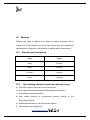
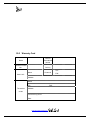
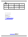
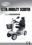
USER MANUAL Unlimited Electric Recreational Vehicle Viking 4X4 OB-EW-001 www.discovermymobility.com Viking 4X4 Power Recreational Vehicle Owner’s Manual Thank you for choosing a Observer Mobility Products. We are proud of the quality construction of every chair we build. This owner’s manual explains the operation of your new chair. Please read it carefully as it contains important safety, care and maintenance information. Observer Mobility’s Power Recreational Vehicle will comply with all the enclosed basic specifications. As a manufacturer of Recreational Vehicles, Observer Mobility endeavors to supply a wide variety of features and options to meet the needs of the user. However, final selection and specifications of the type of Recreational Vehicle to be used by any individual rests solely with the user and his/her healthcare professional capable of making such a selection. All of the information and specifications in this document are current at the time of printing. However due to our policy of continual product improvements we reserve the right to make changes at any time without notice. This may lead to slight variations between the illustrations and explanations in this manual and the model you have purchased. 1.1 Intended Use: The intended use of a Observer Mobility Power Recreational Vehicle is to provide mobility to persons with a maximum weight of 429 lbs, that have the capability of operating a powered Recreational Vehicle. If you experience any problems with your power chair that you are unable to solve, or if you do not feel capable of safely following any of the instructions and/or recommendations as contained in this manual, please contact your Observer Mobility dealer. You will find the model designation and serial number of the Recreational Vehicle on the base of the frame. Observer Mobility is not liable for damage to property or personal injury arising out of unsafe use of a power chair. Observer Mobility is also not liable for any property damage or personal injury arising out of the failure of any person and/or user to following the instructions and recommendations set forth in this manual. Safety and Damage Warnings Throughout this manual, you will find the following safety and damage warnings. www.discovermymobility.com CONTENTS 1.0 Introduction ........................................................................................................... 1 1.a Safety, Warnings, Precautions & Contraindications….. ....................................... 1 2. Transfers................................................................................................................ 1 3. Motor Vehicle Transport ....................................................................................... 1 4. Weight Limitation ................................................................................................. 2 5. Stairs & Escalators ................................................................................................ 2 6. Transportation Products ........................................................................................ 2 7. Public Roads & Streets ......................................................................................... 2 8. Stationary Obstacles: (Steps, Curbs, Etc.) ............................................................ 3 9. Climbing or Descending an Incline ...................................................................... 3 10. Maximum Recommended Incline ......................................................................... 3 11. Removable Parts ................................................................................................... 4 12. Cornering Information .......................................................................................... 4 13. Electromagnetic Fields.......................................................................................... 4 14. Positioning Belts ................................................................................................... 5 15. Weather Precautions .............................................................................................. 5 16. Reaching and Bending .......................................................................................... 5 www.discovermymobility.com 17. Prescription Drugs/Physical Limitations .............................................................. 5 18. Operating While Under The Influence Of Alcohol ............................................... 5 19. Purchase Agreement.............................................................................................. 6 20. Feedback ............................................................................................................... 6 OPERATION ................................................................................................................. 6 21. The Basic Ability Of The User ............................................................................. 6 22. Operating Your Recreational Vehicle .................................................................... 7 23. Maintenance And Repairs. .................................................................................... 8 24. Operating The Grandienter Or Auto Leveling System.. ....................................... 8 25. Adjusting Width And Height Of Armrest.. ........................................................... 9 26. Electromagnetic Interference (EMI) From Radio Wave Sources ....................... 10 26.1 CONTROLLER OPERATION ......................................................................... 13 27. Joystick Power .................................................................................................... 13 28. Rain and Water .................................................................................................... 13 29. Controller Program ............................................................................................. 14 30. Operating Conditions .......................................................................................... 14 31. Cleaning .............................................................................................................. 14 32. Freewheel Mode – pushing the power chair: ...................................................... 14 33. Operating Recreational Vehicle & Controls........................................................ 14 34. Joystick ............................................................................................................... 17 34.2 Buttons .............................................................................................................. 17 34.3 LCD Screen ....................................................................................................... 19 www.discovermymobility.com 34.4 Charger Socket .................................................................................................. 19 34.5 Screen Symbols ................................................................................................. 20 34.6 Top Bar.............................................................................................................. 20 34.7 Base Bar ............................................................................................................ 21 34.8 Main Screen Area ............................................................................................ 221 34.9 Locking the Control System---Keypad Locking............................................... 22 40. Settings Menu ..................................................................................................... 23 41. Battery Charging ................................................................................................. 24 42. Getting Ready to Drive ....................................................................................... 26 43. ASSEMBLY ........................................................................................................ 27 43.1 Components Illustration .................................................................................... 27 43.2 Initial Assembly ................................................................................................ 27 43.3 Tire Assembly ................................................................................................... 28 43.4 Tire Inflation ..................................................................................................... 28 44. Battery Replacement ......................................................................................... 30 45. BATTERIES AND CHARGING ...................................................................... 31 45.1 Silicone Battery characteristics ......................................................................... 31 45.2 Advantages ........................................................................................................ 32 45.3 Charging the batteries ....................................................................................... 33 46. CARE AND MAINTENANCE ........................................................................ 35 46.1 General Guidelines............................................................................................ 36 47. Checks – Daily, Wekly, Monthly & Annulaly................................................... 40 www.discovermymobility.com 48. Storage .............................................................................................................. 36 49. Breakdown Overhaul Guide ............................................................................. 40 50. Warranty parts and period ................................................................................. 41 51. SPECIFICATION ............................................................................................. 44 www.discovermymobility.com INTRODUCTION 1. Safety Please read and follow all instructions in this owner’s manual before attempting to operate your power chair for the first time. If there is anything in this manual you do not understand, or if you require additional assistance for setup, contact your Magic Mobility Dealer before operating the Recreational Vehicle. There are certain situations, including some medical conditions, where the power chair user will need to practice operating the power chair in the presence of a trained attendant. A trained attendant can be defined as a family member or care professional specially trained in assisting a power chair user in various daily living activities. The contents of this manual are based on the expectation that a qualified healthcare professional has properly fitted the power chair to the user and the prescribing healthcare professional has trained the user in the operation of the Recreational Vehicle, the dangers that can be encountered and assured themselves that the user is capable of this. Using your Observer Mobility product safely also depends upon your own good judgment and/or common sense, as well as that of your provider, caregiver, and/or health professional. Observer Mobility is not responsible for injuries and/or damage resulting from any person’s failure to follow the warnings, cautions and instructions in this owner’s manual. 2. Transfers It is recommended that you have a trained attendant present while you learn to transfer yourself. To reduce the chance of injury, we recommend: · Be sure the power is turned off (See section 6.5.4) · Be sure the Power chair is not in freewheel mode (See section 5.3) · Ensure armrests and footrests are swung away or removed · Position yourself as far back as possible in the power chair seat to prevent the power chair from tipping forward. 3. Motor Vehicle Transport Recreational Vehicle positioning belts were not designed with the intent of providing proper restraint during motor vehicle transportation. The Department of Transportation has not approved any tie-down systems with specific Recreational Vehicles for transportation of a user while in a Recreational Vehicle, in a moving vehicle of any type. www.discovermymobility.com -1- It is Observer Mobility’s position that Recreational Vehicle users are not transported in vehicles of any kind while in Recreational Vehicles. 4. Weight Limitations Your power chair is rated for a maximum weight capacity of 400 lbs (see table). Do not carry passengers or heavy weights on any part of the Recreational Vehicle. 5. Stairs and Escalators 6. Transportation Products If it is necessary to use a transportation product such as a hoist or lift, Observer Mobility recommends that the manufacturer’s instructions and specifications are closely reviewed before using that product. 7. Public Streets and Roadways www.discovermymobility.com -2- 8. Stationary Obstacles: (Steps, Curbs, Etc.) Proceed with extreme caution when driving near raised surfaces, unprotected ledges, and/or drop-offs (curbs, porches, stairs, escalators, lifts etc). Always approach an obstacle so both front wheels touch that obstacle together. Never attempt to climb a curb or obstacle at an angle. 9. Climbing or Descending an Incline When climbing an incline, try to keep your power chair moving; however do not use excessive speed. If you must stop, start up again slowly and then accelerate cautiously. If at anytime you feel uncomfortable, reduce your acceleration rate. When driving down an incline, set your power chair to the slowest speed setting and drive in the forward direction only. If your power chair starts to move down the incline faster than you anticipated or desired, allow it to come to a complete stop by releasing the joystick. Once the chair has stopped push the joystick forward slightly to ensure a safely controlled descent. The following advice is recommended for your safety: * Do not drive at an angle up or down the face of the incline. Drive your power chair straight up or down the incline. This greatly reduces the possibility of tipping the chair over. · Avoid potentially hazardous inclines e.g. areas covered with snow, ice, mud, cut grass, or wet leaves. * Avoid sudden stops and starts * When on any sort of an incline or decline, never place the power chair in freewheel mode while seated on it or standing next to it. * Never attempt to travel backwards down an incline. 10. Maximum Recommended Incline Most public access ramps have a maximum gradient 1 in 14 (AS1428.1). Therefore, Observer Mobility recommends that the maximum slope of an incline you attempt to www.discovermymobility.com -3- safely ascend or descend on your power chair does not exceed a 1 in 14 gradient. 11. Removable Parts 12. Cornering Information Excessively high cornering speeds can create the possibility of tipping. If you feel that you may tip over in a corner, immediately reduce your speed and steering angle (i.e. lessen the sharpness of the turn) The following advice is recommended for your safety: * Reduce cornering speed * Reduce steering angle * Beware of uneven, rough and slippery terrain * Avoid turning on inclined surfaces * Be aware of changing surfaces - such as passing from a paved area to a gravel area at high speed while turning. * Avoid abrupt directional changes. 13. Electromagnetic Fields (more information is on page 10) Your power chair’s performance may be influenced by electromagnetic fields caused www.discovermymobility.com -4- by mobile telephones or other radiating devices, such as hand-held radios, radio and television stations, wireless computer links, microwave sources, and pagers. Your power chair may also be a source of electromagnetic and radio frequency interference. Be aware that your power chair may affect the performance of alarm systems and other radiating devices. 14. Positioning Belts Do not sit on your power chair while it is in a moving vehicle refer to section 3.2 Motor Vehicle Transport. It is the obligation of the purchasers, therapists and other healthcare professionals to determine if a positioning belt is required to ensure the safe operation of this equipment by the user. 15. Weather Precautions 16. Reaching and Bending 17. Prescription Drugs/Physical Limitations Consult your physician if you are taking prescribed or over-the-counter medication or if you have certain physical limitations. 18. Alcohol www.discovermymobility.com -5- 19. Purchaser’s Agreement By accepting delivery of this product, you promise that you will not change, alter, or modify this product. In addition you agree not to remove any safety features or alter the Recreational Vehicle in anyway. Finally you agree not to; fail, refuse, or neglect to install any retrofit kits from time to time provided by Observer to enhance or preserve the safe use of this product. 20. Feedback We want to hear your questions, comments, and suggestions about your new Recreational Vehicle and the service you received from your authorized agent. You can send us E-mail or refer to our website FAQ section. Contact us at : (866) 878-9294 OPERATION 21. The basic ability of the user 1. The user must have the physical ability and intellect to operate the electric Recreational Vehicle safely. A user that has vision problem or mental retardation, should not operate this Recreational Vehicle without a professional recommendation. 2. The user needs the ability to keep their torso balanced. In the event user is unable to keep their torso balanced, user should consult a specialist before using. There are chest straps and chest vest available that may allow a user without the ability to balance their torso to use this Recreational Vehicle safely. www.discovermymobility.com -6- 3. A user with limit neck control or range may not have the ability to operate this Recreational Vehicle and should only use this Recreational Vehicle after receiving the recommendation to do so by a specialist. A rear view mirror is available if the specialist feels it would be suitable. 4. A user must hold enough knowledge of the operation of a power Recreational Vehicle before operating this Recreational Vehicle. In the event a user does not they should receive instructions from a specialist and do not operate this Recreational Vehicle until that specialist tells them it is safe o do so. 22. Operating Your Recreational Vehicle 1. Use must read and follow all instructions and notes in this manual before attempting to operate your power Recreational Vehicle for the first time. 2. This power Recreational Vehicle is meant for only one purpose. Do not modify for any reason. 3. Before formally using your new Recreational Vehicle you should practice at open space to be familiar with all of its functions and use. 4. Users must where their seat belt when in use at all times. 5. While up and down slopes, please operate at slowest speed for safety, www.discovermymobility.com -7- meanwhile, please turn on the gradienter switch to maintain a level seating position. 6. While turning left or right, 360° revolving or turning at any angle, Recreational Vehicle must be on slow speed in order to protect the motors and damage to components. 23. Maintenance And Repairs. Maintenance and repairs may only be performed by a licensed Observer Mobility technician. DO NOT at any time attempt to repair or work on this Recreational Vehicle unless you have been trained and licensed by Observer Mobility. 24. Operating The Grandienter Or Auto Leveling System. Please follow the instruction below (based on the controller at the right side): www.discovermymobility.com -8- Normal state The gradienter does not work. Working Click on the button to ON and the green light is lighted.The gradienter in normal operation. Reset automatically If the gradienter detect the maximum crawl angle, it will stop working and the green light went out. Just click to OFF and wait for 2 seconds, then click the button to RST, the red light is lighted, The gradienter will reset automatically, the chair will reset to horizontal position. Working again Click to OFF and wait for 2 seconds, then click on the button to ON, the green light is lighted, the gradienter in normal operation station again. 25. Adjusting the width and height of the armrest as needed: www.discovermymobility.com -9- www.discovermymobility.com - 10 - 26. Electromagnetic Interference (EMI) From Radio Wave Sources. CAUTION: IT IS VERY IMPORTANT THAT YOU READ THIS INFORMATION REGARDING THE POSSIBLE EFFECTS OF ELECTROMAGNETIC INTERFERENCE ON YOUR POWERED RECREATIONAL VEHICLE Powered Recreational Vehicles may be susceptible to electromagnetic interference (EMI), which is interfering electromagnetic energy (EM) emitted from sources such as radio stations, TV stations, amateur radio (HAM) transmitters, two way radios, and cellular phones. The interference (from radio wave sources) can cause the powered Recreational Vehicle to release its brakes, move by itself, or move in unintended directions. It can also permanently damage the powered Recreational Vehicle’s control system. The intensity of the interfering EM energy can be measured in volts per meter (V/m). Each powered Recreational Vehicle can resist EMI up to a certain intensity. This is called its “immunity level.” The higher the immunity level, the greater the protection. At this time, current technology is capable of achieving at least a 20 V/m immunity level, which would provide useful protection from the more common sources of radiated EMI. This powered Recreational Vehicle model as shipped, with no further modification, has an immunity level of 3 V/m. There are a number of sources of relatively intense electromagnetic fields in the everyday environment. Some of these sources are obvious and easy to avoid. Others are not apparent and exposure is unavoidable. However, we believe that by following the warnings listed below, your risk to EMI will be minimized. The sources of radiated EMI can be broadly classified into three types: 1) Hand-held portable transceivers (transmitters-receivers) with the antenna mounted directly on the transmitting unit. Examples include: citizens band (CB) radios, "walkie talkie," security, fire, and police transceivers, cellular telephones, and other personal communication devices. **NOTE: Some cellular telephones and similar devices transmit signals while they are ON, even when not being used; 2) Medium-range mobile transceivers, such as those used in police cars, fire trucks, ambulances, and taxis. These usually have the antenna mounted on the outside of the vehicle; and www.discovermymobility.com - 11 - 3) Long-range transmitters and transceivers, such as commercial broadcast transmitters (radio and TV broadcast antenna towers) and amateur (HAM) radios. NOTE: Other types of hand-held devices, such as cordless phones, laptop computers, AM/FM radios, TV sets, CD players, and cassette players, and small appliances, such as electric shavers and hair dryers, so far as we know, are not likely to cause EMI problems to your powered Recreational Vehicle. Powered Recreational Vehicle Electromaqnetic Interference (EMI) Because EM energy rapidly becomes more intense as one moves closer to the transmitting antenna (source), the EM fields from hand-held radio wave sources (transceivers) are of special concern. It is possible to unintentionally bring high levels of EM energy very close to the powered Recreational Vehicle's control system while using these devices. This can affect powered Recreational Vehicle movement and braking. Therefore, the warnings listed below are recommended to prevent possible interference with the control system of the powered Recreational Vehicle. WARNINGS Electromagnetic interference (EMI) from sources such as radio and TV stations, amateur radio (HAM) transmitters, two-way radios, and cellular phones can affect powered Recreational Vehicles and motorized scooters. Following the warnings listed below should reduce the chance of unintended brake release or powered Recreational Vehicle movement which could result in serious injury. 1) Do not operate hand-held transceivers (transmitters-receivers), such as citizens band (CB) radios, or turn ON personal communication devices, such as cellular phones, while the powered Recreational Vehicle is turned ON; 2) Be aware of nearby transmitters, such as radio or TV stations, and try to avoid coming close to them; www.discovermymobility.com - 12 - 3) If unintended movement or brake release occurs, turn the powered Recreational Vehicle OFF as soon as it is safe; 4) Be aware that adding accessories or components, or modifying the powered Recreational Vehicle, may make it more susceptible to EMI (Note: There is no easy way to evaluate their effect on the overall immunity of the powered Recreational Vehicle) 5) Report all incidents of unintended movement or brake release to the powered Recreational Vehicle manufacturer, and note whether there is a source of EMI nearby. Important Information 1) 20 volts per meter (V/m) is a generally achievable and useful immunity level against EM1 (as of May 1994) (the higher the level, the greater the protection); 2) This product has an immunity level of 3 V/m. www.discovermymobility.com - 13 - PG CONTROLLER OPERATION The joystick controls may be customized and may be one of a number of different models depending upon users requirements. This manual contains information on the standard joystick control. 27. Joystick power If the power Recreational Vehicle begins to move in an unexpected manner, immediately release the joystick and turn the Recreational Vehicle off. Unless the joystick is damaged, this should stop your power chair. If the joystick is not in the neutral (centre) position when you turn on the power, you may cause a fault in the system. Releasing the joystick and turning the power off and on again will reset the system. WARNING ! In case of unexpected movement turn off the power and gradienter switch. 28. Rain and Water The joystick hand control unit IS NOT WATERPROOF. The joystick module is splash proof but may be permanently damaged if water transgresses the rubber seals (this damage is not covered under warranty). We recommend carrying a plastic bag large enough to cover the joystick module and the user’s hand, in case of rain. www.discovermymobility.com - 14 - 29. Controller program The controller program affects speed, acceleration, deceleration, and braking. The drive mode settings are preset at the factory. 30. Operating Conditions Your control system uses industrial-grade components throughout, ensuring reliable operation in a wide range of conditions. However, you will improve the reliability of the control system if you keep exposure to extreme conditions to a minimum. Do not expose your control system or its components in damp environments for prolonged periods. If the control system becomes contaminated with food or drink clean it off as soon as possible after turning off the power. 31. Cleaning Clean the control system and the joystick with a cloth dampened with diluted detergent. Be careful when cleaning the joystick and screen. Never use abrasive or spirit-based cleaners. 32. Freewheel Mode – pushing the power chair 33. Operating Recreational Vehicle & Controls The Viking is equipped with a manual freewheel system enabling the electromagnetic brakes to be disengaged and the power Recreational Vehicle to be maneuvered manually. To disengage the built-in brakes simply pull the two levers. The Recreational Vehicle controls will not function and the “status” light on the joystick will flash when the chair is in free-wheel mode. This feature has been intentionally incorporated to protect the user from unsafe situations. Don’t forget to push the levers back in again firmly after you are done manually positioning the chair. The R-net control system has two versions of Joystick Module – with and without lighting control. Most of the controls are common to both. Each of the controls is explained within this section. www.discovermymobility.com - 15 - 34. Joystick www.discovermymobility.com - 16 - 34.1 Joystick The primary function of the joystick is to control the speed and direction of the Recreational Vehicle. The further you push the joystick from the center position the faster the Recreational Vehicle will move. When you release the joystick the brakes are automatically applied. If the Recreational Vehicle is fitted with actuators, the joystick can also be used to move and select actuators, refer to section 5.5 for more details. 34.2 Buttons 1. On/Off Button The On/Off button applies power to the control system electronics, which in turn supply power to the Recreational Vehicle’s motors. Do not use the On/Off button to stop the Recreational Vehicle unless there is an emergency. (If you do, you may shorten the life of the Recreational Vehicle drive components). 2. Horn Button The Horn will sound while this button is depressed. www.discovermymobility.com - 17 - 3. Speed Decrease Button This button decreases the maximum speed setting. Depending on the way the control system has been programmed a momentary screen may be displayed when the button is pressed. Refer to section 5 for details of the momentary screen. 4. Speed Increase Button This button increases the maximum speed setting. Depending on the way the control system has been programmed a momentary screen may be displayed when the button is pressed. Refer to section 5 for details of the momentary screen. 5. Mode Button The Mode button allows the user to navigate through the available operating Modes for the control system. The available modes are dependent on programming and the range of auxiliary output devices connected to the control system. 6. Profile Button The Profile button allows the user to navigate through the available Profiles for the control system. The number of available Profiles is dependent on how the control system is programmed. Depending on the way the control system has been programmed a momentary screen may be displayed when the button is pressed. Refer to section 5 for details of the momentary screen. 7. Hazard Warning Button and LED This button activates and de-activates the Recreational Vehicle’s hazard lights. Depress the button to turn the hazards on and depress the button again to turn them off. When activated the hazard LED and the indicator LEDs will flash in sync with the Recreational Vehicle’s indicators. 8. Lights Button and LED This button activates and de-activates the Recreational Vehicle’s lights. Depress the button to turn the lights on and depress the button again to turn them off. When activated the lights LED will illuminate. www.discovermymobility.com - 18 - 9. Left Indicator Button and LED This button activates and de-activates the Recreational Vehicle’s left indicator. Depress the button to turn the indicator on and depress the button again to turn it off. When activated the left indicator LED will flash in sync with the Recreational Vehicle’s indicator(s). 10. Right Indicator Button and LED This button activates and de-activates the Recreational Vehicle’s right indicator. Depress the button to turn the indicator on and depress the button again to turn it off. When activated the right indicator LED will flash in sync with the Recreational Vehicle’s indicator(s). 11. External On/Off Switch Jack This allows the user to turn the control system on and off using an external device, such as a buddy button. 12. External Profile Switch Jack This allows the user to select Profiles using an external device, such as a buddy button. To change the Profile whilst driving simply press the button. If the control system is set to latched drive or actuator control operation, then the polarity of the jack input is reversed to effect a fail safe system; meaning this input will provide an External Profile Switch function and an Emergency Stop Switch function. The Joystick Module is supplied with rubber bungs that must be inserted into the Jack Socket when no external device is connected. 34.3 LCD Screen The status of the control system can be understood by observing the LCD screen. The control system is on when the screen is backlit. Refer to section 5 for details on screen symbols. www.discovermymobility.com - 19 - 34.4 Charger Socket This socket should only be used for charging or locking the Recreational Vehicle. Do not connect any type of programming cable into this socket. Refer to section13 for more details on charging. This socket should not be used as a power supply for any other electrical device. Connection of other electrical devices may damage the control system or affect the E.M.C. performance of the Recreational Vehicle. The control system’s warranty will be voided if any device other than the battery charger supplied, with the Recreational Vehicle, or the lock key is connected into this socket. 34.5 Screen Symbols The Drive screen for the R-net has common components, which will always appear, and components that will only appear under certain conditions. Below is a view of a typical Drive screen in Profile 1. 34.6 Top Bar Battery Indicator This displays the charge available in the battery and can be used to alert the user to the status of the battery. Steady: This indicates that all is well. Flashing Slowly: The control system is functioning correctly, but you should charge the battery as soon as possible. www.discovermymobility.com - 20 - Stepping Up: The Recreational Vehicle batteries are being charged. You will not be able to drive the Recreational Vehicle until the charger is disconnected and you have switched the control system off and on again. 34.7 Base Bar Current Profile The currently selected Profile is shown in numeric form. 34.8 Main Screen Area 1. Profile Name This is a text string that displays the name of the currently selected Profile. 2. Clock This displays the current time in a numeric format. The clock is user adjustable. Adjustable options are: • Visibility, whether the clock is displayed on screen. • The display format, 12 or 24 hour. • The time, the user can adjust the time. These adjustments are made within the Settings Menu. Refer to section 8 for details. 3. Speed Indicator www.discovermymobility.com - 21 - This displays the current speed setting. The speed setting is adjusted using the Speed Buttons. 4. Maximum Speed Indicator This displays the current maximum speed setting. 5.Digital Speed Display This displays the actual speed of the Recreational Vehicle derived from the motors. The display can be set to mph or km/h. 34.9 Locking the Control System---Keypad Locking To lock the Recreational Vehicle using the keypad; • While the control system is switched on, depress and hold the On/Off button. • After 1 second the control system will beep. Now release the On/Off button • Deflect the joystick forwards until the control system beeps. • Deflect the joystick in reverse until the control system beeps. • Release the joystick, there will be a long beep. • The Recreational Vehicle is now locked. The following screen will be displayed, the next time the Control System is switched on. To unlock the Recreational Vehicle: • If the control system has switched off, press the On/Off button. • Deflect the joystick forwards until the control system beeps. • Deflect the joystick in reverse until the control system beeps. www.discovermymobility.com - 22 - • • 40. Release the joystick, there will be a long beep. The Recreational Vehicle is now unlocked. Settings Menu The Settings Menu allows the user to adjust the CJSM display in terms of clock adjustment and display format, the brightness of the backlight, the background color and the behavior of the odometer. The menu is accessed by depressing the Speed Down and Speed Up buttons simultaneously. A typical Settings Menu display would be as below. Each of the menu items are described in the following sections. Set Time A right joystick deflection will enter a clock adjustment screen in which further joystick deflections are used to set the time. Display Time This sets the format of the time display or turns it off. The options are 12hr, 24hr or Off. Left and right joystick deflections are used to change between the options. Distance This sets the functionality of the odometer and a screen as below will appear. www.discovermymobility.com - 23 - Total Distance This is a value held in the Power Module and relates to the total distance driven using that Power Module. Trip Distance This is a value held in the CJSM and relates to the total distance driven since the last reset. Display Distance Sets whether Total Distance or Trip Distance appears as the odometer display on the CJSM. Clear Trip Distance A right joystick deflection will clear the Trip Distance value. Exit A right joystick deflection will return to the Settings Menu. Backlight This sets the intensity of the LCD backlight. The adjustable range is 0% to 100% in steps of 10%. Adjustments are made with left and right joystick deflections. Background This sets the color of the screen background. Blue is the standard, but in very bright sunlight then a white background will make the display more visible. The options are Blue, White and Auto. Left and right joystick deflections are used to change between the options. Blue: means the background will be blue in all Profiles. White: means the background will be white in all Profiles. Auto means the color will be set by the programmable parameter, Background, which can be set to be different across the Profiles. For example, blue for the slower Profiles that are for indoor use and white for the faster Profiles intended for outdoor use. For more details of the parameter, Background, refer to the relevant section in the Programming chapter. IR Setup IR Set up allows the user access the Omni IR (Infra Red) menus. For full details on how to learn, delete and use the IR functions available please refer to the R-net Omni Technical Manual SK78813. Exit Exits the Settings Menu back to normal operation. 41. Battery Charging To charge the Recreational Vehicle batteries connect the charger plug into the www.discovermymobility.com - 24 - battery charger socket on the R-net JSM. You will not be able to drive the Recreational Vehicle when the charger is connected. To connect the charger plug, ensure the single pin is at the bottom, as shown in the following illustration, then offer the charger plug to the R-net in a horizontal orientation. The molded guide on the R-net will help you to locate the plug. Ensure the plug is pushed fully in position. www.discovermymobility.com - 25 - 42. Getting Ready to Drive Your Viking 4X4 Operate the On/Off switch. The screen will go through an initializing process then show the base screen as follows. In the case on an LED Joystick Module the battery gauge will illuminate. Check that the Speed Setting is at a level that suits you. Push the joystick to control the speed and direction of the Recreational Vehicle. If you push the joystick before or just after you switch the control system on, the screen will flash the joystick displaced screen. You must release and center the joystick to resume normal operation. If you do not release the joystick within five seconds the Recreational Vehicle will not be able to move, even if you release the joystick and push it again. The screen will display the diagnostic screen at this time. You can reset this condition by switching the control system off and on again. Joystick lead If for any reason, the joystick lead is disconnected take care when reconnecting, do not force the plug into the socket. The lead is polarized and should only be fitted one way. www.discovermymobility.com - 26 - ASSEMBLY 43. 43.1 Components Illustration Initial Assembly Your power chair may require some assembly either before initial use or after transportation. It may also require disassembly to make some comfort adjustments. Figure 2 on next page details those Parts of the power chair that are designed to be disassembled and assembled by an end user Or by a qualified caregiver before using the product or making comfort adjustment. www.discovermymobility.com - 27 - 43.2 Tire Assembly Figure 3 Figure4 Follow these easy steps for a quick and safe repair for the solid tires: 1. 2. 3. 4. 5. 6. 7. 8. 9. Turn off the power to the controller. Set the power chair up on the blocks. Remove the drive wheel nut and washer from the axle. See figure3. Pull the wheel off the axle. Remove the screws from the rim assembly and separate the front and rear rim, See firgure4. Reassembly the rims and reinstall the screws. Slide the wheel back onto the axle. Make sure that the key is in the axle slot. Reinstall the drive wheel nut and washer onto the axle and tighten. Remove the power chair from the blocks. www.discovermymobility.com - 28 - 43.3 Tire Inflation Tire pressures should be checked weekly. All pneumatic tires are fitted with automotive type valves and can be inflated using most typical automotive hand and foot type pumps as well as service station air outlets. www.discovermymobility.com - 29 - 44. Battery Replacement Replacing batteries steps First,screw off the four thumb screws back of the wheel cover, and lift up back cover gently,then loose the batteries belt,and disconnect the batteries fastener, last take out the first battery.(see picture) Push the batteries back from the front,until the second batteries to the position of the first one.disconnect the positive wrie with a small screwdriver,then take the second battery.Do the same and disconnect the third negative wire, then take out all the batteries.(as shown) All batteries being taken out(as shown),disconnect the connecting line and install them on the new batteries,Repeat the above steps in opposite way and install batteries,you have complete it. 1. 2. 3. 4. 5. Place the batteries back into the power base from the rear base. Fasten the battery strap around the rear battery. Connect each battery harness to his mating plug on the power base. Reinstall the rear cover and the front cover. Charge the batteries. www.discovermymobility.com - 30 - 45. BATTERIES AND CHARGING 45.1 y y y y y y y y y y Silicone Battery characteristics Optimized for high current discharges Greensaver batteries are superior at discharging large currents. Our products are able to discharge 30c in 8 Seconds without damage to the battery. Reduced charging time Greensaver batteries can be recharged via large currents of up to 0.5~1.0 c. this allows charging time to be greatly reduced. It only takes 30 minutes to achieve an 80% recharge, and no more than 3 hours for a 100% complete charge. Enhanced capacity Greensaver batteries hold more change and have much higher capacity than other batteries its class. Long battery life Under normal operation and usage, Greensaver batteries have a 10 years float life, and are able to last up to>400 deep cycles. Minimal self-discharge Self-discharge in Greensaver batteries are greatly reduced. Not only is charging no longer required within one year prior to use, it has an extended shelf life 400% of typical average lead acid batteries. Maintains high capacity under low temperatures Greensaver batteries are able to hold 70~75% of their total charge under temperatures of -10°c Extended operating temperature range Able to withstand and operate under the harshest of environments, Greensaver products are able to operate normally from -50°c ~ +60°c with margins to spare. No memory effects, and maintenance free sealed design Greensaver batteries do not suffer from memory effects during recharges and discharges. Our products are also maintenance free designed to aid your convenience. No acidic vapors created, electrolyte is environmentally friendly Our unique and patented silicate compound electrolyte does not create acidic vapors during charging. The electrolyte itself is also non hazardous and environmentally friendly. Low internal resistance Using the silicate compound electrolyte, internal resistance is greatly reduced. Thus, high temperatures do not result from charging, and risks of explosion are eliminated. www.discovermymobility.com - 31 - 45.2 Advantages Silicate compound electrolyte Developed by Greensaver Corporation, the new electrolyte allows for an unprecedented breakthrough in the global energy market. The electrolyte is non-corrosive, and environmentally friendly. Our technology is patent-verified in more than 10 countries worldwide. As attested, such state-of-the-art technology has never been witnessed until today, and has thus received the highest grading, as, in all qualifications. At the same time, the electrolyte allows for enhanced capacity, extended lifespan, high current discharge superiority, rapid recharge time, and superior low temperature performances. Our deep-sea models have been tested to work optimally at great depths. Along with our experienced team of engineers and professional management group, it is our company’s foremost goal to bring safe, natural, and environmentally friendly energy to the world. Sealed silicone power battery & sealed lead-acid battery comparison. Test description Typical maintenance free lead acid battery Maintenance free silicone power battery Specific energy(c20) 35-40 wh/kg 45-50wh/kg Electrolyte Sulfuric acid Silicate compound Standard charge time (constant current and charge) 4-8h 1-2h Fast charge time (constant current and charge) 2-3h 0.5-1h Self--discharge loss / standard shelf life without charging 5% per month/3-6month First month 4%, declines after the second month, maintains at 90% after a year / 1-2 years High current capability 3-7c 15-30c Ability to recover from over-design Fair Excellent Low temperature performance Performance plummets Below 0°C Functions normally at-50°C Optimal operating temperature range Needs ambient temperature adjustments from-50°C to 60ºC Environmental friendliness Allows for minor acid vapor No acid vapor at all www.discovermymobility.com - 32 - No control needed 45.3 Charging Batteries The battery charger is essential in providing long life for your electric Recreational Vehicle’s batteries. The battery charger is designed to optimize your electric Recreational Vehicle’s performance by charging the batteries safely, quickly, and easily. To charge the batteries using the off-board charger: 1. Position your electric Recreational Vehicle next to a standard electrical outlet. 2. Be certain the controller power is turned off and the power chair is in drive. 3. Plug the off-board charger programming socket on the controller. 4. Plug the off-board charger into the electric outlet. 5. During charging, the red lights on the controller are flashing in turn. When fully charged, all the lights will turn solid green, no flashing. 6. When the batteries are fully charged , unplug the off-board charger from the electrical outlet and then from the controller. 7. Never use an extension cord to plug in your battery charger. Plug the charger directly into a properly wired standard electrical outlet. You must recharge your power chair’s batteries with the supplied charger. Do not use an automotive-type battery charger. 8. Do not expose the battery charger to rain or other source of moisture unless it has been tested for outdoor use. Explosive gases may be generated while charging the batteries. Keep the power chair and battery charger away from sources of ignition such as flames or sparks and provide adequate ventilation when charging the batteries. Inspect the battery charger, wiring, and connectors for damage before each use. 9. Do not attempt to open the battery charger case. If the battery charger does not appear to be working correctly, contact your authorized provider. 10. Do not allow children to play near the power chair while charging. Observer recommends that you do not charge the batteries while the power chair is occupied. Do not expose charger to extreme weather conditions. If the battery charger is exposed to extreme weather conditions, then it must be allowed to adjust to the difference in environmental conditions before use indoors. Refer to the manual supplied with the battery charger for more information. www.discovermymobility.com - 33 - 45.4 To get the maximum range from your batteries: ∗ Fully charge the batteries prior to the trip ∗ Avoid stop-go driving; try to maintain a constant speed ∗ Try to avoid inclines ∗ Limit baggage weight carried 45.5 Public Transportation The Gel Cell batteries are Federal Aviation Administration (FAA) approved, allowing safe transportation on aircraft, buses and trains. However, we recommend that any specific requirements of the carrier are checked in advance. 45.6 Battery Disposal and Recycling If you encounter a damaged or cracked battery, contact your Observer Mobility Dealer for instructions on disposal. Your Observer Mobility Dealer will also have all the necessary information on battery recycling, which is our recommended course of action. www.discovermymobility.com - 34 - 46. CARE AND MAINTENANCE The electric Recreational Vehicle is a sophisticated mobility vehicle. Like any motorized vehicle, it requires routine maintenance checks. You can perform some of these checks, but others require assistance from an authorized Provider. Preventive maintenance is very important. If you follow the maintenance checks in this section as scheduled, you can help ensure that your Recreational Vehicle gives you years of trouble-free operation. If you have any doubt as to your Recreational Vehicle’s care or operation, contact an authorized Provider. WARNING! Direct or prolonged exposure to water or dampness could cause the electric Recreational Vehicle to malfunction electronically and mechanically. Water can cause electrical components to corrode and the chair’s frame to rust. Electric Recreational Vehicle should be examined periodically for signs of corrosion caused by water exposure, bodily fluids exposure, or incontinence. Damaged components should be replaced or treated immediately. What should you do when your electric Recreational Vehicle touched water? 1. Dry your electric Recreational Vehicle as thoroughly as possible with a towel. 2. Allow your electric Recreational Vehicle to sit in a warm, dry place for 12 hours to allow unseen water to evaporate. 3. Check the joystick and the brakes before using your electric Recreational Vehicle again. 4. If any inconsistencies are found, take your electric Recreational Vehicle to your authorized Provider. Electric Recreational Vehicle that is frequently exposed to sources of water, such as incontinence, should be inspected often www.discovermymobility.com - 35 - for corrosion and electronic components may need to be replaced frequently. Temperature Some of the parts of your electric Recreational Vehicle are susceptible to extreme changes in temperature. Always keep your electric Recreational Vehicle between the temperatures of -20°C and50°C. In extremely cold temperatures the batteries may freeze. The specific temperature at which they freeze depends on a number of factors, such as battery charge, usage, and composition of the batteries. Temperatures above 50°C may cause your electric Recreational Vehicle to operate at a reduced speed. This reduced speed is a safety feature built into the controller that helps prevent damage to the motor and other electrical components. 46.1 General Guidelines Avoid knocking or bumping the controller, especially the joystick. Avoid prolonged exposure of your Chair to extreme conditions, such as heat, cold, or moisture. Keep the controller clean. Check all connectors to ensure that they are all tight and secured properly. WARNING! Even though the electric Recreational Vehicle has passed the necessary testing requirements for ingress of liquids, you should keep electrical connections away from sources of dampness, including direct exposure to water or bodily fluids and incontinence. Check electrical components frequently for signs of corrosion and replace as necessary. www.discovermymobility.com - 36 - 47. Daily Checks With the controller turned off, check the joystick. Make sure it is not bent or damaged and that it returns to the neutral position when you release it. Check the rubber boot around the base of the joystick for damage. Visually inspect the boot. Do not handle or try to repair it. See an authorized Provider if there is a problem. Visually inspect the controller cable. Make sure that it is not frayed, cut, or has any wires exposed. See an authorized Provider if there is a problem. Check for flat spots on solid tires. Flat spots could adversely affect stability. 47.1 Weekly Checks Disconnect and inspect the controller from the power base. If there is any corrosion, contact an authorized Provider if necessary. Ensure that all parts of the controller system are securely fastened to your electric Recreational Vehicle. Calibrate the joystick if a noticeable difference in performance is detected or if the joystick does not operate properly. To calibrate the joystick, power off the unit, place the joystick in the neutral position, and power the unit back on. If a problem still exists with your joystick’s performance, contact an authorized Provider. Check the brakes. This test should be carried out on a level surface with at least 3 feet (1 meter) of clearance around your Recreational Vehicle. Check the brakes www.discovermymobility.com - 37 - 1. Turn on the controller and turn down the speed level of your electric Recreational Vehicle. 2. After one second, check the battery condition meter. Make sure that it remains on. 3. Slowly push the joystick forward until you hear the electric brakes click. Immediately release the joystick. You must be able to hear each electrical brake operating within a few seconds of joystick movement. Repeat this test three times, pushing the joystick backwards, then left, and then right. 47.2 Monthly Checks Check for drive tire wear. See an authorized Provider for repair. Keep your electric Recreational Vehicle clean and free of foreign material, such as mud, dirt, hair, food, drink, etc. 47.3 Yearly Checks Take your Recreational Vehicle to an authorized Provider for yearly maintenance. This helps ensure that your electric Recreational Vehicle is functioning properly and helps prevent future complications. 48. Storage Your electric Recreational Vehicle should be stored in a dry place, free from extreme temperature. When storing, disconnect the batteries from the Recreational Vehicle. See VI. “Batteries and Charging.” Batteries that are stored in extreme temperatures or stored without a full charge may be permanently damaged, causing unreliable performance and limited service life. It is recommended that you charge the batteries periodically throughout www.discovermymobility.com - 38 - periods of prolonged storage. Lifting the frame of the Recreational Vehicle to raise the wheels off of the ground during periods of prolonged storage will eliminate flat spots from developing. 48.1 Cleaning and Disinfection Use a damp cloth and mild, non-abrasive cleanser to clean the plastic and metal parts of your electric Recreational Vehicle. Avoid using products that may scratch the surface of your electric Recreational Vehicle. If necessary, clean your product with an approved disinfectant. Make sure the disinfectant is safe for use on your product before application. WARNING! Never use any chemicals to clean a seat, as they may cause the seat to become crack. Use soapy water and dry the seat thoroughly. 48.2 Wheel Replacement If your chair is equipped with a solid tire insert, then you must replace the whole wheel assembly;If your chair is equipped with a beach tire, which maximum charge pressure or pressure range is 2Kpa.when you replace the beach tire to solid tire, you must exchange the whole wheel assembly. Follow The Steps Below: 1. Turn off the power to the controller. 2. Set the electric Recreational Vehicle up on blocks. 3. Remove the drive wheel nut and washer from the axle. 4. Pull the wheel off the axle. 5. Slide new wheel back on the shaft. Make sure that the key is in the axle slot. www.discovermymobility.com - 39 - 6. Reinstall the drive wheel nut and washer onto the axle and tighten. 7. Remove the electric Recreational Vehicle from the blocks. 49. Breakdown Overhaul Guide Maintenance & repairs should only be performed by a certified technician. Please refer or check following table, in order to find possible problems. Some simple check you can perform to solve the problem and restore normal operation. If you have questions please contact an authorized provider. Test Item Handle Motor Battery Horn Seat Screw Tire Content for checking Are they loosened? Can they move from left to right? Is the moving sound abnormal? Do the electromagnetic brakes work? Does the power indicator light up? Is there a sufficient charge? Does the horn make a sound? Does the operating lever of seat work normally? Can it move from left to right smoothly? Are there any loosened screws? Are they cracked or damaged? Is there any strange sounds? Others Is anything Vehicle? www.discovermymobility.com - 40 - leaking from the Recreational 50. Warranty Observer will repair or replace at our option to original purchaser, free of charge, any of the following parts found upon examination by an authorized representative of Observer to be defective in material and/or workmanship: 50.1 50.2 Warranty parts and period Items Period Motor 12 months Battery 6 months Controller 12 months Frame 24 months The following situation beyond our warranty scope a) User did not follow instructions in the user manual. b) User neglected the Recreational Vehicle and did not maintain it. c) Exceeding the period of warranty. d) User voided warranty by unauthorized persons working on the Recreational Vehicle. e) authorized modification of the Recreational Vehicle. f) Exceeding the user weight limit. www.discovermymobility.com - 41 - 50.3 Warranty Registration Required Purchaser must complete and mail warranty registration card. Mail To: 24711 Sherwood Centerline Mi. 48015. 50.4 Special Declaration In the event a user does not operate the Recreational Vehicle according to the instructions, thus causing damage. Damage under these circumstance is not covered under the warranty. The warranty provided with the purchase of the Viking power Recreational Vehicle is intended to protect the buyer from manufacture defects and does not cover any other circumstance. www.discovermymobility.com - 42 - 50.5 Warranty Card Mode Color of Recreational Vehicle Proforma Invoice No.: Date of Delivery Name: Contact #: User’s info.: Address: Name: TEL: The service FAX: Address: center Authorized Signature: Date: www.discovermymobility.com - 43 - TEL: FAX: Service number Service Confirmation The responsible person of service center signature: Date: User: Date: . 51. SPECIFICATIONS Overall length 980mm Weight with batteries 197kg Overall width 730mm Max load capacity 150kg Overall height 1370mm Max speed 7.5km/h Wheel size(front/rear) Ø400mm Seat-to-floor height 680mm Max mileage 15-20km Chassis-to-floor height 115mm Operation time 2-5 h Charging time 4-6 h Brake Electromagnetic braking Driving Motor 2 x 1200W Seat Height of obstacle to Span Stair/curb climbable angle(Max.) Max output rotate speed High-back/Low-back seat 16”/18”/20” ≤the chassis height (for driving motor) 63rpm 25°(it depends) (Step height≤110mm) www.discovermymobility.com - 44 - Slope climbable angle(Max.) 45°(it depends) Level rack Motor 0° Silicone Battery Turning radius 1 x 200W 12V,27AH ,4pcs Silicone power battery Electronics Level equipment(patented) PG R-NET Controller Dealer Contact Information Discover Your Mobility Inc. 32 10 Mile Rd. Hazel Park Mi. 48030 Toll Free: (866) 868-9694 Fax: (877) 772-9197 Email: [email protected] http://www.discovermymobility.com www.discovermymobility.com - 45 - Drive manner Four-wheel drive