1
FEI-Zyfer
CommSync II/GSync Serial Communication Protocol
Serial Communication Protocol
385-8002
Rev AU
CommSync II Product Family
(CommSync II, CommSync II-D, GSync, GSync II)
ALL SPECIFICATIONS SUBJECT TO CHANGE WITHOUT NOTICE
FEI-Zyfer
7321 Lincoln Way, Garden Grove, CA 92841-1428 USA
Phone: (714) 933-4003 Fax: (714) 933-4001
385-8002 Rev AU
© 2010 FEI-Zyfer Inc. All rights reserved.
FEI-Zyfer
DATE
03/06/2001
03/13/2001
08/01/2001
09/21/2001
12/17/2001
03/27/2002
06/11/2002
07/16/2002
10/30/2002
01/21/2003
02/24/2003
04/10/2003
11/19/2003
12/10/2003
01/29/2004
02/04/2004
03/18/2004
06/18/2004
09/29/2004
10/06/2004
10/28/2004
12/07/2004
02/14/2005
04/18/2005
08/08/2005
01/03/2006
01/25/2006
01/25/2006
05/25/2006
09/07/2006
05/04/2007
05/15/2007
06/17/2007
2/7/2008
03/27/2008
01/08/09
2/26/09
6/23/09
02/02/10
CommSync II Product Family Serial Communication Protocol
REVISIONS
Rev A: Add SAASM-specific commands.
Rev B: Add Time Code Module commands.
Rev C: Add DTF-specific cmds, SAASM cmds, and correct typo’s.
Rev D: Add Input Module cmds.
Rev E: Add Frequency cmds. Update commands/responses.
Rev F: Add 1MHz Sine and TTL modules, and Ethernet I/O Ext Input Module (385-4038)
command/responses
Rev G: Incorporate commands for GSync. Add SNMP information.
Rev H: Correct SSTA message for GSync and add module information.
Rev J: Add table to clarify SSTA message for GSync. Add NTPC controls for GPS and manual time
modes.
Rev K: Add velocity (VELO) command.
Rev L: Remove unused command (MODS).
Correct typographical error in NOTE for UNSL command.
Change NTPC command for new TFOM specification.
Update CLKR command for Dual Clk Rate N.8 Modules.
Rev M: Correct typo in TIME command.
Add information for IRIG Input Module
Add YEAR command
Rev N: Add commands for SVER, DAFR commands
Correct ETHM command.
Correct typographical errors.
Add Ethernet Telnet password commands
Rev P: Add Telnet EXIT command
Rev R: Add IRGC command.
Update Position, and position mode commands.
Rev S: Add ECHO command and MD5, Symmetric Ethernet functions
Rev T: Remove ability to modify GPS position.
Rev U: Add ability to set IRIG output mode (IRGM).
Rev V: Add Cross-Discipline variable to DISC command, correct errors.
Rev W: Correct typographical errors. Add information on DISC command.
Rev Y: Add HQTC, and HQTS commands for Have Quick output modules
Rev Z: Changed the definition of Cold Start command.
Rev AA: Updated IP addresses due to network modification.
Rev AB: Add CLKN and PHAC commands for N.1 and Phase Aligned LPN Output modules
Rev AC: Add EXTD command
Rev AD: Add SAASM Hot Start (ENHS), and KDP version (KVER) commands
Rev AE: Add DNTI, DNTG, DNTM, and DNTV commands to support the Dual NTP output module
Rev AF: Added Note that the commands (DNTI, DNTG, and DNTM) will reset the port, inhibiting new
commands until the port is ready.
Rev AG: Added new Ethernet board commands, ADMC, and UPLD to support TFPT system firmware
upgrades.
Rev AH: Added RFC 1305 information to NTPC command description, and added control slot
information for GSync-II and CommSync-II-D.
Rev AJ: Added commands for 385-4090 Dual Ethernet module.
Corrected description for EXTD, PRID commands, and TFOM range in TIME and SSTA msg
Rev AK: Added STAT description
Rev AL: Changed all commands to 4 char format, Corrected format errors
Rev AM: Added $RSTG,K command and SAASM MPE firmware (407-3003) specific parameters,
updated FEI-Zyfer address
Rev AN:Correct the weblink to Zyfer support page in the web
Rev AP: Add PTP module specific commands
Rev AR: Add PTP Slave Specific commands, and Correct Typos
Rev AS: Add PTP OSTP Cmd, and Documented NMEA messages
Rev AU: Removed reference to cold start trap.
385-8002 Rev AU
© 2010 FEI-Zyfer Inc. All rights reserved.
2
FEI-Zyfer
CommSync II Product Family Serial Communication Protocol
Table of Contents
CommSync II Product Family Communication - Introduction................................. 6 Get Online GPS (Output) ..........................................................................AGPS ..........................9 Antenna Cable Delay Value (Output)......................................................ANTD ........................10 Set Antenna Cable Delay Value (Input/Output) ....................................ANT1/ANT2...............10 GTF#1/GTF#2 Azimuth and Elevation (Output)....................................AZEL/AZL1/AZL2 ......11 Beep On/Off (Input) ..................................................................................BEEP.........................12 1/2 Channel Clock Rate Control (ClkRt, Dual ClkRt, and N.8) ..........CLKR
13 4/6 Channel Clock Rate Control (N.1 Modules)(Input/Output) .........CLKN.........................14 Disable Antenna Fault Reporting (Input) ...............................................DAFR ........................15 DAC Control (Output) ...............................................................................DACV ........................16 Read Dual NTP IP Address cmd(Output) ..............................................DNTI..........................17 Read Dual NTP Network Gateway Address(Output) ...........................DNTG ........................18 Read Dual NTP NetMask(Output)...........................................................DNTM........................19 Read Dual NTP Module Firmware versions(Output)............................DNTV ........................20 Internal(GPS)/External Discipline Control (Input/Output) ...................DIS1/DIS2 .................21 External Discipline Frequency Selection (Input/Output) ......................DIV1/DIV2 .................22 External 1 PPS Delay Adjustment ..........................................................EXTD.........................23 Frequency Module Control (Input/Output) ............................................FREQ ........................24 GPS engine type (output) .........................................................................GPSE ........................26 Have Quick Output Module Clock Enable selection (Input/Output) ...HQTC ........................27 Have Quick Output Module HQ format command (Input/Output).......HQTS ........................28 Input Module Configuration (Output/Input).............................................INPC..........................29 IRIG input control (Input)...........................................................................IRGC .........................31 Lock Keypad Edit Key (Input)...................................................................LOCK ........................33 Phase Aligned Low Phase Noise Calibration command (Input/Output) PHAC .................34 Phase Aligned module Calibration Procedure................................... ..................................35 Antenna Mask Angle (Input/Output)........................................................MAG1/MAG2 .............36 Read Manual Time Mode (Output)..........................................................MANM .......................37 Not Time-Lock Counter (Output) .............................................................NTL1/NTL2................38 Position Mode for Online GPS (Output) .................................................TRMO/PMD1/PMD2..39 Latitude and Longitude and Elevation Position (Output) .....................SPOS/POS1/POS2 ...40 Product ID (Output)....................................................................................PRID/PRD1/PRD2.....41 Reset GPS Receiver (Input).....................................................................RSG1/RSG2..............42 Satellite Signal Quality (Output)...............................................................SIGQ/SIGP/SIGS ......43 System Status (Output).............................................................................SSTA.........................44 Time Code Output Module Control (Input/Output)................................TCOD ........................49 Internal Temperature (Output) .................................................................TEMP/TMP1/TMP2 ...50 Time (Output)..............................................................................................TIME..........................51 Time Mode (Input/Output).........................................................................TIMM .........................52 Set or Clear Unsolicited Flag (Input/Flag) ..............................................UNSL.........................53 Read Velocity (Output/Flag) .....................................................................VELO/VEL1/VEL2 .....54 Get Current Firmware Version (Output) .................................................VERS/VER1/VER2....55 Set Year (Input/Output) .............................................................................YEAR ........................56
NMEA Message support ................................................................... ..................................57 GPRMC Message ......................................................................................GRMC .......................58 GPGLL Message........................................................................................GGLL.........................59 GPGSV Message.......................................................................................GGSV........................60 GPGSA Message.......................................................................................GGSA........................61
385-8002 Rev AU
© 2010 FEI-Zyfer Inc. All rights reserved.
3
FEI-Zyfer
CommSync II Product Family Serial Communication Protocol
Ethernet-Specific Commands .................................................................................. 62 Set/Read Ethernet I/O IPv4 Address (Output) ......................................ETHI ..........................63 Set/Read Ethernet I/O IPv4 NetMask (Output) .....................................ETHM ........................64 Set/Read Ethernet I/O IPv4 Gateway Address (Output, 385-4038/385-4090) ETHG.......65 Set/Read Ethernet I/O Trap Destination Address (Output, 385-4038/385-4090) ETHT ...66 IPv4 and IPv6 Addressing notes ....................................................... ..................................67 Set/Read Ethernet I/O IPv6 Address (Output, 385-4090 only) ...........ET6I...........................68 Set/Read Ethernet I/O IPv6 NetMask (Output 385-4090 only) ...........ET6M.........................69 Set/Read Ethernet I/O IPv6 Gateway Address (Output 385-4090 only) ET6G .................70 Read Ethernet I/O Firmware Version (Output) ......................................ETHV.........................71 Password Control Enable/Disable (Input, Admin only) ........................PSWC .......................72 Password Control Enable/Disable (Output, Admin only) .....................PSWC .......................72 Change Administrator Name/Password (Input, Admin only)...............ADMC........................73 Add a user (Input, Admin only) ................................................................USRA ........................73 Delete a user (Input, Admin only) ............................................................USRD ........................74 List user (Output, Admin only) .................................................................USRL.........................74 Change password (Input) .........................................................................PSWD .......................75 Read Telnet/SSH control setting (Output, 385-4090 only) ..................NCON........................76 Exit Telnet Session (Input) .......................................................................EXIT ..........................77 Telnet ECHO controls (Input/Output)......................................................ECHO........................77
NTP Server commands ............................................................................................. 78 Network Time Protocol (NTP) Time Source Control (Input/Output)...NTPC ........................78 Read NTP Mode (Output, 385-4038 only) .............................................NTPM ........................79 Read NTP Mode (Input/Output, 385-4090 only) ...................................NTPO ........................80 Read NTP Broadcast configuration (Output, 385-4090 only) .............NTPB.........................81 Read NTP IPv4 Broadcast IP address (Input, 385-4090 only) ...........NTBI ..........................82 Set NTP IPv4 Broadcast IP address (Input, 385-4090 only)...............NTBI ..........................82 Set/Read NTP IPv6 Multicast IP address (Input, 385-4090 only) ......NB6I ..........................83 MD5 NTP Authentication overview....................................................84 Symmetric NTP mode overview ........................................................84 Read MD5 Key Table(Output)..................................................................NTPK.........................85 Set/modify MD5 Key (Input, 385-4038 only)..........................................NTPI ..........................86 Add MD5 Key (Input, 385-4090 only)......................................................NTKA.........................87 Delete MD5 Key (Input, 385-4090 only) .................................................NTKD ........................87 Read NTP Peer Address (Output)...........................................................NTPJ .........................88
IEEE1588/2008 Precision Time Protocol (v2) (PTP)................................................ 90
PTP protocol operating mode (Input/Output)(Master/Slave)...............PTPM ........................91 PTP Default Port Data Setting (Input)(Master/Slave)...........................PSET.........................92 PTP Announce Message Interval Rate (Input/Output)(Master/Slave) ANNR ...................93 PTP Set Master Priority (Input/Output)(Master) ....................................SPRI..........................94 Set PTP Master Domain (Input/Output)(Master/Slave)........................MASD........................95 PTP Sync Message Interval Rate (Input/Output)(Master) ...................SYNR ........................96 Delay Request Interval Rate (Input/Output)(Master)............................DELR.........................97 PTP V2 One Step Mode (Input/Output)(Master) ...................................OSTP ........................98 Add UniCast Master (Input/Output)(Slave) ...........................................UCMA........................99 Delete UniCast Master (Input/Output)(Slave) .......................................UCMD .......................99 List UniCast Master (Input/Output)(Slave) .............................................UCML ......................100 Display PTP clock ID (Master/Slave/Measurement, Output only) ......CKID........................100 Network Measurement Master Clock Accuracy (Measurement, Output only) DTIM .......101 SNMP Command Structure .................................................................................... 102 385-8002 Rev AU
© 2010 FEI-Zyfer Inc. All rights reserved.
4
FEI-Zyfer
CommSync II Product Family Serial Communication Protocol
STAT output message description ....................................................103 Set TRAP output selection (Input 385-4090 only) ................................TSTA .......................103 Set SSTA Verbose output (Telnet port, Input 385-4090 only) ............STAT .......................103 1a System STAT message (Output only) ..............................................STAT,Sys Modes ....104 1b. System STAT message (Output only) , STAT,System, GTF TFOMS ..........................105 2a. GTF Status, STAT message (Output only) .....................................STAT,GTF...............106 2b. GTF Fault Status, STAT message (Output only) ..........................STAT,GTF...............107 3b. Output module STAT message (Output only) ................................STAT,Slot................109 Set/read SNMP Version (Input/Output, 385-4090 only).......................SNMV......................110 Set Read/Get community name (input, 385-4090 only).......................RNMP......................111 Set Write/Set community name (input, 385-4090 only) .......................WNMP.....................111 Set/Read SNMPv3 security levels/options (385-4090 SNMPv3 only) SNMK................112 View SNMPv3 Access Control Mode (385-4090 SNMPv3 only) .......VACM......................113
FEI-Zyfer MIB structure: ......................................................................................... 114 SNMP Command table...................................................................... ................................115 UpDate system firmware(Input, 385-4038/385-4090/385-4097) ........UPLD.......................117
PPS (SAASM) Commands ** .................................................................................. 118 PPS initialization command** (Input) ......................................................DRY1/DRY2 ............119 Hot Start Enable command (Input)..........................................................ENH1/ENH2 ............120 PPS receiver Status** (Output)................................................................PSTA/PST1/PST2 ...121 Satellite Signal Status** (Output).............................................................SVS1/SVS2.............122 CV/KDP Status** (Output) ........................................................................CVS1/CVS2 ............123 SAASM Block1 and Block2 data** (Output)...........................................SAB1/SAB2.............124 SAASM Receiver Version ** (Output) .....................................................SVR1/SVR2 ............125 Index of Commands by Function....................................................... ................................126 385-8002 Rev AU
© 2010 FEI-Zyfer Inc. All rights reserved.
5
FEI-Zyfer
CommSync II Product Family Serial Communication Protocol
CommSync II Product Family Communication - Introduction
The CommSync II/GSync systems have two serial communication ports.
The main serial/command port for CommSync II connects through the backplane
to either a CMD I/O module (RS-232 interface) or an Ethernet I/O module. This
port uses the proprietary ASCII FEI-Zyfer Command protocol, listed by command
in this manual.
The second port is a Debug port. On the CommSync II and CommSync II-D the
port is on the GTF/DTF front panel. For GSync and GSync II, the port is on the
back panel. This port communicates via RS-232 uses the same ASCII FEI-Zyfer
Command protocol, and provides a download/test port to the module.
Serial Communication Protocol
The communication protocol consists of ASCII character strings composing
command/response sentences where each command can be queried for a
response.
Each command sentence is starts with an ASCII ‘$’, followed by the command
word (4 ASCII characters) followed by the ‘*’ character and a carriage
return/linefeed (<cr/lf>).
Each response sentence begins with an ASCII ‘$’ followed by the command word
and response, and the ‘*’ character. After the ‘*’ delimiter, there is a 2-byte
hexadecimal ASCII checksum (cs) followed by a carriage return and a linefeed
(<cs|cr|lf>).
The checksum is calculated by X-ORing each successive byte in the message
sentence between but not including the ‘$’ and ‘*’ characters. The checksum is
not needed for sending commands to the GTF Module. However, the GTF Module
will always include checksums in its sentences sent back through the
communications port to the user.
Command Queuing
The GTF send and receive buffers are approximately 2048 bytes deep. This will
allow several messages to be queued one after another, for multiple responses. If
the receive buffer gets full, the remaining commands will be truncated. A default
baud rate of 19200 or greater is recommended for optimum performance.
Unsolicited Response
Several commands can be enabled for an unsolicited output. By enabling the
unsolicited flag, the requested data will output at periodic intervals or when new
information is available. The unsolicited flag is enabled and disabled by use of the
UNSL command. See the UNSL command for more information.
Redundant GTF/DTF Module Commands (CommSync II/CommSync II-D Only)
The GTF/DTF modules are self-contained GPS Time and Frequency sub-systems
and, as such, will receive commands and operate on them independently of the
other module. In order to maintain communication with both modules in a
CommSync II system a primary and secondary command structure has been
maintained.
385-8002 Rev AU
© 2010 FEI-Zyfer Inc. All rights reserved.
6
FEI-Zyfer
CommSync II Product Family Serial Communication Protocol
The GTF/DTF module plugged into slot 1 (left slot, from the front) is defined as
GTF/DTF#1 or the primary module, while the GTF/DTF plugged into slot 2 (right
slot) is designated GTF/DTF#2 or the secondary module.
In most cases there will be three command sets. As an example the read internal
temperature command TEMP, will output the temperature of the Online module.
The independent commands TMP1 and TMP2 will respond with the internal
temperature of the GTF/DTF in the respective slots.
Non-redundant GTF/DTF Module Commands (CommSync II, CommSync II-D or
GSync, GSync II)
For non-redundant systems (a CommSync II with a single GTF/DTF, or a GSync
system), all commands are directed to GTF/DTF#1. This module will always be
the online module. Commands such as TIMD will be sent to and received from the
single GTF/DTF. Commands directed to specific modules, such as TMD1, must
use the primary module identification (such as “1” or “P”). Commands directed to
secondary modules, such as TMD2 or SIGS, will be ignored.
NOTE: In non-redundant systems, references to “online module” always refer to
GTF/DTF#1.
385-8002 Rev AU
© 2010 FEI-Zyfer Inc. All rights reserved.
7
FEI-Zyfer
CommSync II Product Family Serial Communication Protocol
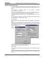
Windows/HyperTerminal Setup
In most Windows-based computers is a terminal program called HyperTerminal.
The set up of HyperTerminal to communicate with a CommSync II/GSync is very
simple.
The
program
is
usually
installed
Files\Accessories\HyperTerminal
in
the
directory:
C:\Program
Double Click on the program “Hypertrm.exe” and a screen will appear asking for a
connection description: Enter a name for the setup, and press OK.
On the next screen select Direct to Com 1 (or any available port on your PC) and
press OK.
The next screen will request Port Settings. The default communication settings
are 19200 Baud, 8 bit, no parity, and 1 stop bit.
Set the following:
Bits per second = 19200, Data Bits= 8, Parity= None, Stop Bits= 1, Flow Control=
None
Finally, from the File pull down menu, select properties, Select the Settings tab,
and press the ASCII Setup button. Verify that the Send line ends with line feeds
box is checked off. Click OK, and then
OK to the Properties box.
Verify
you are
connected and enter the following command on the PC Key Board to test the
HyperTerminal-to-CommSync II/GSync interface:
$PRID* <cr|lf>
This command will return the Product Identification Value. See PRID command
for details.
Note: For non-redundant CommSync II and GSync systems, commands directed
to GTF/DTF#2 will be ignored. Only commands for GTF/DTF#1 are valid in these
systems.
385-8002 Rev AU
© 2010 FEI-Zyfer Inc. All rights reserved.
8
FEI-Zyfer
CommSync II Product Family Serial Communication Protocol
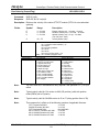
Get Online GPS (Output)
AGPS
Command:
$AGPS*<cr|lf>
Response:
$AGPS,N*<cs|cr|lf>
Description: Returns the current physical Online GTF/DTF number. As a clarification,
GTF/DTF#1 refers to the module plugged into front panel slot 1 of the main frame
and GTF/DTF#2 refers the module plugged into front panel slot 2.
Fields:
Note:
Symbol
Range
Description
N
1 or 2
Physical GTF/DTF module.
Online commands are only applicable to redundant CommSync II systems.
Set Online GTF/DTF Module (Input)
Command:
$AGPS,n*<cr|lf>
Response:
$AGPS,n*<cs|cr|lf>
AGPS
Description: Sets Online GTF/DTF module, if selected GTF/DTF module is ready.
Fields:
Note:
Symbol
Range
Description
N
1 or 2
Physical GTF/DTF module.
This command is in effect for in all versions CommSyncII family firmware.
385-8002 Rev AU
© 2010 FEI-Zyfer Inc. All rights reserved.
9
FEI-Zyfer
CommSync II Product Family Serial Communication Protocol
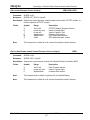
Antenna Cable Delay Value (Output)
Command:
$ANTD*<cr|lf>
Response:
$ANTD,N*<cs|cr|lf>
ANTD
Description: Reads the antenna cable delay compensation value/internal timing offset of the
online GTF module (For non-redundant CommSync II or GSync systems, this will
be GTF#1).
Fields:
Symbol
Range
Description
N
0 to 999999
nanoseconds
Set Antenna Cable Delay Value (Input/Output)
Command:
$ANTg,N*<cr|lf>
Command:
$ANTg*<cr|lf>
Response:
$ANTg,N*<cs|cr|lf>
ANT1/ANT2
Description: Sets/reads the GTF#1/GTF#2 antenna cable delay compensation in a GTF
receiver.
Fields:
Symbol
Range
Description
g
N
1-2
0 to 999999
GTF number
nanoseconds
Example:
$ANT1,234*<cr|lf>
Response:
$ANT1,000234*<cs|cr|lf>
This example will set the antenna cable delay value to 234 nanoseconds for the
GTF#1. Propagation delay for most cable is approximately 1.5 nanoseconds per
foot. Thus, for a 100-foot cable the antenna cable delay value should be set to
150 ns.
Note:
For GSync or non-redundant CommSync II system, use the ANT1 command. The
ANT2 command has no effect.
Note:
This command is in effect for in all versions CommSyncII family firmware.
385-8002 Rev AU
© 2010 FEI-Zyfer Inc. All rights reserved.
10
FEI-Zyfer
CommSync II Product Family Serial Communication Protocol
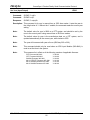
GTF#1/GTF#2 Azimuth and Elevation (Output)
AZEL/AZL1/AZL2
Command:
$AZL1*<cr|lf>
Response:
$AZL1,N,S,E,A, . . . S,E,A*<cs|cr|lf>
Description: Outputs the satellite PRN followed by the elevation in degrees above the horizon
and azimuth in degrees relative to true north of the GTF#1/GTF#2 antenna. This
command message contains data for up to twelve (12) satellites.
Fields:
Symbol
Range
Description
N
S
00 to 12
00 to 32
E
A
00 to 90
000 to 359
Satellites in view
Sat PRN number. A 00 will indicate that there is no
information available.
Elevation
Azimuth
Note:
For GSync or non-redundant CommSync II system, use the AZL1 command. The
AZL2 command has no effect.
Note:
This command is in effect for in all versions CommSyncII family firmware.
385-8002 Rev AU
© 2010 FEI-Zyfer Inc. All rights reserved.
11
FEI-Zyfer
CommSync II Product Family Serial Communication Protocol
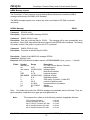
Beep On/Off (Input)
BEEP
Command:
$BEEP,N*<cr|lf>
Response:
$BEEP,N*<cs|cr|lf>
Description: This command enables or disables the 1PPS beep. The speaker is located on the
KDC (Key Pad display) module. The command is received by either GTF and
passed to the KDC.
Fields:
Symbol
Range
Description
N
1 or 0
1 = On, 0 = Off
Note:
This command has no effect in systems with no KeyPad Display.
Note:
This command is in effect for in all versions CommSyncII family firmware.
385-8002 Rev AU
© 2010 FEI-Zyfer Inc. All rights reserved.
12
FEI-Zyfer
CommSync II Product Family Serial Communication Protocol
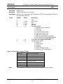
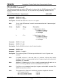
1/2 Channel Clock Rate Control (ClkRt, Dual ClkRt, and N.8 Modules)(Input/Output) CLKR
Command:
$CLKR*<cr|lf>
Response:
$CLKR,S T R1 R2,S T R1 R2,…..*<cs|cr|lf>
Description:
This command reads the output module slots and finds Clock Rate Output modules, and reports slot
numbers, ID’s, and rate selection registers.
Note:
Single Clock Rate modules have only one register and will, therefore, only respond with R1. See
Example.
Fields:
Symbol
Range
Description
S
T
R1
R2
1-15
32-37
1-256
1-256
Output Module Slot Number
Output Module Identification
Register A Frequency output multiplier
Register B, Frequency output multiplier
Note:
For N.8 versions, R1 and R2 range is 1 to 1024. See table below.
Example:
$CLKR*<cr|lf>
Response:
$CLKR,4 36 125 193,7 31 256*<cs|cr|lf>
In the example the system contains two Clock Rate modules. In Slot 4 is a Dual Clock Rate TTL
Module, with Register A set for 1 MHz (125) and Register B set for 1.544 MHz (193). In slot 7 is a
single Clock Rate Module, with its output set for 2.048 MHz (256). See Table below for Clock Rate
Module ID values.
Setting Clock Rates
CLKR
Command:
$CLKR,S,R,V*<cr|lf>
Response:
$CLKR,S,R,V*<cs|cr|lf>
Description:
This command sets the Clock Rate registers to the desired output frequency,
kHz times the variable ‘V’).
Fields:
Symbol
Range
Description
S
R
V
1-15
1-2
1-256
Output Module Slot Number
Register A/B Selection
Frequency output multiplier
(FOUT = 8
Note:
For N.8 versions, V range is 1 to 1024. See table below.
Example:
$CLKR,4,1,16*<cr|lf>
Description:
This command is addressed to a Clock Rate Module in slot 4 and will set Register A to 128 kHz (8
kHz times 16).
ID
0x32
0x34
0x35
0x36
0x37
Note:
P/N
385-4016
385-4029
385-4030
385-4068
385-4069
ClkRt, Dual ClkRt, and N.8 Module IDs
Description
Clock Rate Fiber Optic Output Module
Dual Clock Rate TTL Output Module
Dual Clock Rate RS-422 Output Module
Dual Clock Rate N.8 TTL Output Module
Dual Clock Rate N.8 RS-422 Output Module
This command is in effect as of the following versions of applicable firmware.
GTF Firmware 385-3022
SAASM Firmware 385-3021
DTF Firmware 385-3031
Mk IV GTF/DTF Firmware 407-3001
Mk IV SAASM Firmware 407-3002
Mk IV SAASM Firmware 407-3003
385-8002 Rev AU
V1.20.00
V1.19.00
V1.05.00
V1.01.00
V1.01.00
V1.00.00
© 2010 FEI-Zyfer Inc. All rights reserved.
13
FEI-Zyfer
CommSync II Product Family Serial Communication Protocol
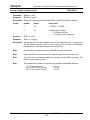
4/6 Channel Clock Rate Control (N.1 Modules)(Input/Output)
CLKN
Command:
$CLKN*<cr|lf>
Response:
$CLKN,S T F*<cs|cr|lf>
Description:
This command reads the output module slots and finds the N.1 Clock Rate Output
modules, and reports slot numbers, ID’s, and Module Fault Status.
Fields:
Symbol
Range
Description
S
T
F
1-15
66-67
66-67
Output Module Slot Number
Output Module Identification
Output Module Status
Example:
$CLKN*<cr|lf>
Response:
$CLKN,3 66 00,8 67 00,*<cs|cr|lf>
In the example the system contains two N.1 Clock Rate modules. In Slot 3 is a 4 channel
N.1 Clock Rate Module, and in slot 8 is a 6 channel N.1 Clock Rate Module
Command:
$CLKN,S,R*<cr|lf>
Response:
$CLKN,S,R,F*<cs|cr|lf>
Description:
This command sets or reads the frequency setting of the output module in the specified
slot and channel, and returns the slot and channel numbers as well as rate selection.
Fields:
Symbol
Range
S
R
F
1-15
Output Module Slot Number
1-6
Output Channel
1000-54000000 Output Frequency Selection
Description
Note:
N.1 Rate selectable from 1kHz to 54MHz in 10Hz increments
Command:
$CLKN,3,3*<cr|lf>
Response:
$CLKN,3,3,12000000*<cs|cr|lf>
Description:
This command reads/sets the Clock Rate register 3 on the board in slot 3 to the desired
output frequency, (12 MHz).
Fields:
Symbol
Range
S
R
F
1-15
Output Module Slot Number
1-6
Register A/B Selection
1000-54000000 Output Frequency Selection
ID
0x66
0x67
0x67
0x66
Note:
P/N
385-4072-01
385-4072-02
385-4072-03
385-4072-04
Description
CLOCK RATE MODULE IDs
Description
4 channel, 1K-54M, BNC/TTL N.1 module
6 channel, 1K-54M, DB9/RS422 N.1 module
6 channel, 1K-54M, WireWrap/RS422 N.1 module
4 channel, 1K-54M, TriAx/RS422 N.1 module
This command is in effect as of the following versions of applicable firmware.
GTF Firmware 385-3022
SAASM Firmware 385-3021
DTF Firmware 385-3031
Mk IV GTF/DTF Firmware 407-3001
Mk IV SAASM Firmware 407-3002
Mk IV SAASM Firmware 407-3003
385-8002 Rev AU
V1.32.00
V1.30.00
V1.11.00
V1.01.00
V1.01.00
V1.00.00
© 2010 FEI-Zyfer Inc. All rights reserved.
14
FEI-Zyfer
CommSync II Product Family Serial Communication Protocol
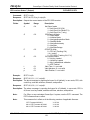
Disable Antenna Fault Reporting (Input)
Command:
$DAFR,N*<cr|lf>
Response:
$DAFR,N*<cs|cr|lf>
DAFR
Description: This command enables or disables the antenna overcurrent and undercurrent
fault. The fault will not be displayed in the SSTA message, on the GTF LEDs, or
on the KDC Menu 0. The command disables or enables antenna fault reporting in
both GTFs.
Fields:
Note:
Symbol
Range
Description
N
1 or 0
1 = Fault reporting disabled,
0 = Fault reporting enabled.
This command is in effect as of the following versions of applicable firmware.
GTF Firmware 385-3022
SAASM Firmware 385-3021
DTF Firmware 385-3031
Mk IV GTF/DTF Firmware 407-3001
Mk IV SAASM Firmware 407-3002
Mk IV SAASM Firmware 407-3003
385-8002 Rev AU
V1.21.00
V1.21.00
Not Applicable
V1.01.00
V1.01.00
V1.00.00
© 2010 FEI-Zyfer Inc. All rights reserved.
15
FEI-Zyfer
CommSync II Product Family Serial Communication Protocol
DAC Control (Output)
DACV
Command:
$DACV*<cr|lf>
Response:
$DACV,N*<cs|cr|lf>
Description: Reads the DAC value of the GTF/DTF module.
Fields:
Symbol
Range
Description
N
0 - 65535
DAC value, control voltage for oscillator. Center
value of 32768.
GTF/DTF#1/GTF/DTF#2 DAC Control (Output)
Command:
$DACP,N*<cr|lf>
Command:
$DACP*<cr|lf>
Response:
$DACP,N*<cs|cr|lf>
DACP/DACS
Description: Reads GTF/DTF#1 DAC value. (For GTF/DTF#2 use DACS)
Fields:
Symbol
Range
N
0 - 65535
Description
DAC value for oscillator where 32768 is center
voltage
Note: The range shown (0-65535) is for the Xtal Oscillator option. With a
Rubidium Oscillator the range is 0 to 32768, with a center value of 16384.
Note:
For GSync or non-redundant CommSync II system, use the DACP command. The
DACS command has no effect.
Note:
This command is in effect for in all versions CommSyncII family firmware.
385-8002 Rev AU
© 2010 FEI-Zyfer Inc. All rights reserved.
16
FEI-Zyfer
CommSync II Product Family Serial Communication Protocol
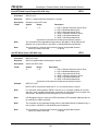
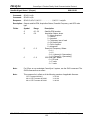
Read Dual NTP IP Address cmd(Output)
DNTI
Command:
$DNTI*<cr|lf>
Response:
$DNTI,s,id,st*<cs|cr|lf>
Fields:
Symbol
Description:
s
2-15
Output Module Slot Number
id
5F
Output Module ID, Dual NTP = 0x5F
st
00-FF
Output Module Status
Reads Slot, Module ID, and Status for all Dual NTP module in a system
Command:
$DNTI,s*<cr|lf>
Response:
$DNTI,s,xxx.xxx.xxx.xxx,yyy.yyy.yyy.yyy*<cs|cr|lf>
Fields:
Symbol
Range
Range
Description
Description
s
2-15
Output Module Slot Number
xxx.xxx.xxx.xxx Port 0, IP address
yyy.yyy.yyy.yyy
Port 1, IP address
Description:
Reads IP Address setting for Dual NTP Modules (385-4087). The first set of numbers is
the IP Address of Port 0, followed by the IP Address for Port 1.
Command:
$DNTI,s,p*<cr|lf>
Response:
$DNTI,s,p,xxx.xxx.xxx.xxx*<cs|cr|lf>
Fields:
Symbol
Description:
s
2-15
Output Module Slot Number
p
0 or 1
Dual NTP port (0,1)
xxx.xxx.xxx.xxx IP address (Selected port)
Reads IP Address setting (by port) for Dual NTP Modules (385-4087).
Range
Description
Set Dual NTP IP Address cmd(Output)
DNTI
Command:
$DNTI,s,p,xxx.xxx.xxx.xxx*<cr|lf>
Response:
$DNTI,s,p,xxx.xxx.xxx.xxx*<cs|cr|lf>
Fields:
Symbol
Range
s
2-15
p
0 or 1
xxx.xxx.xxx.xxx IP address
Description
Output Module Slot Number
Dual NTP port (0,1)
Description:
Sets IP Address setting (by port) for Dual NTP Modules (385-4087).
Note:
The configuration commands (DNTI, DNTG, and DNTM) will reset the port. This will inhibit
new configuration commands until the port is ready (~ 20 seconds).
Note:
This command is in effect as of the following versions of applicable firmware.
GTF Firmware 385-3022
SAASM Firmware 385-3021
Mk IV GTF/DTF Firmware 407-3001
Mk IV SAASM Firmware 407-3002
Mk IV SAASM Firmware 407-3003
385-8002 Rev AU
V1.38.00
V1.36.00
V1.01.00
V1.01.00
V1.00.00
© 2010 FEI-Zyfer Inc. All rights reserved.
17
FEI-Zyfer
CommSync II Product Family Serial Communication Protocol
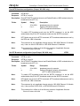
Read Dual NTP Network Gateway Address(Output)
DNTG
Command:
$DNTG*<cr|lf>
Response:
$DNTG,s,id,st*<cs|cr|lf>
Fields:
Symbol
Range
Description
s
id
st
2-15
5F
00-FF
Output Module Slot Number
Output Module ID, Dual NTP = 0x5F
Output Module Status
Description:
Reads Slot, Module ID, and Status for all Dual NTP module in a system
Command:
$DNTG,s*<cr|lf>
Response:
$DNTG,s,xxx.xxx.xxx.xxx,yyy.yyy.yyy.yyy*<cs|cr|lf>
Fields:
Symbol
Description:
Range
Description
s
2-15
Output Module Slot Number
xxx.xxx.xxx.xxx Port 0, Gateway address
yyy.yyy.yyy.yyy
Port 1, Gateway address
Reads Gateway Address setting for Dual NTP Modules (385-4087). The first set is the
gateway setting for Port 0, followed by the gateway setting for Port 1.
Command:
$DNTG,s,p*<cr|lf>
Response:
$DNTG,s,p,xxx.xxx.xxx.xxx*<cs|cr|lf>
Fields:
Symbol
Range
Description
s
2-15
Output Module Slot Number
p
0 or 1
Dual NTP port (0,1)
xxx.xxx.xxx.xxx Gateway (Selected port)
Description:
Reads Gateway setting (by port) for Dual NTP Modules (385-4087).
Set Dual NTP Network Gateway Address(Output)
Command:
$DNTG,s,p*<cr|lf>
Response:
$DNTG,s,p,xxx.xxx.xxx.xxx*<cs|cr|lf>
Fields:
Symbol
Description:
Range
DNTG
Description
s
2-15
Output Module Slot Number
p
0 or 1
Dual NTP port (0,1)
xxx.xxx.xxx.xxx IP address
Sets Gateway setting (by port) for Dual NTP Modules (385-4087).
router/gateway address is needed to communicate to other LAN segments.
The
Note:
The configuration commands (DNTI, DNTG, and DNTM) will reset the port. This will inhibit
new configuration commands until the port is ready (~20 seconds).
Note:
This command is in effect as of the following versions of applicable firmware.
GTF Firmware 385-3022
SAASM Firmware 385-3021
Mk IV GTF/DTF Firmware 407-3001
Mk IV SAASM Firmware 407-3002
Mk IV SAASM Firmware 407-3003
385-8002 Rev AU
V1.38.00
V1.36.00
V1.01.00
V1.01.00
V1.00.00
© 2010 FEI-Zyfer Inc. All rights reserved.
18
FEI-Zyfer
CommSync II Product Family Serial Communication Protocol
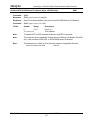
Read Dual NTP NetMask(Output)
DNTM
Command:
$DNTM*<cr|lf>
Response:
$DNTM,s,id,st*<cs|cr|lf>
Fields:
Symbol
Description:
s
2-15
Output Module Slot Number
id
5F
Output Module ID, Dual NTP = 0x5F
st
00-FF
Output Module Status
Reads Slot, Module ID, and Status for all Dual NTP module in a system
Command:
$DNTM,s*<cr|lf>
Response:
$DNTM,s,xxx.xxx.xxx.xxx,yyy.yyy.yyy.yyy*<cs|cr|lf>
Fields:
Symbol
Description:
Range
Range
Description
Description
s
2-15
Output Module Slot Number
xxx.xxx.xxx.xxx Port 0, NetMask
yyy.yyy.yyy.yyy
Port 1, NetMask
Reads Netmask Address setting for Dual NTP Modules (385-4087). The first set of
numbers is the Netmask set on Port 0, followed by the setting for Port 1.
Command:
$DNTM,s,p*<cr|lf>
Response:
$DNTM,s,p,xxx.xxx.xxx.xxx*<cs|cr|lf>
Fields:
Symbol
Range
Description
s
2-15
Output Module Slot Number
p
0 or 1
Dual NTP port (0,1)
xxx.xxx.xxx.xxx NetMask (Selected port)
Description: Reads NetMask setting (by port) for Dual NTP Modules (385-4087).
Set Dual NTP IP Address cmd(Output)
DNTM
Command:
$DNTM,s,p*<cr|lf>
Response:
$DNTM,s,p,xxx.xxx.xxx.xxx*<cs|cr|lf>
Fields:
Symbol
Range
s
2-15
p
0 or 1
xxx.xxx.xxx.xxx Net Mask
Description
Output Module Slot Number
Dual NTP port (0,1)
Description:
Sets NetMask setting (by port) for Dual NTP Modules (385-4087).
Note:
The configuration commands (DNTI, DNTG, and DNTM) will reset the port. This will inhibit
new configuration commands until the port is ready (~20 seconds).
Note:
This command is in effect as of the following versions of applicable firmware.
GTF Firmware 385-3022
SAASM Firmware 385-3021
Mk IV GTF/DTF Firmware 407-3001
Mk IV SAASM Firmware 407-3002
Mk IV SAASM Firmware 407-3003
385-8002 Rev AU
V1.38.00
V1.36.00
V1.01.00
V1.01.00
V1.00.00
© 2010 FEI-Zyfer Inc. All rights reserved.
19
FEI-Zyfer
CommSync II Product Family Serial Communication Protocol
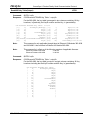
Read Dual NTP Module Firmware versions(Output)
DNTV
Command:
$DNTV,s*<cr|lf>
Response:
$DNTI,s,v*<cs|cr|lf>
Fields:
Symbol
Range
Description
s
v
2-15
string
Output Module Slot Number
Dual NTP module firmware version.
Description:
Reads firmware version of the Dual NTP Module board.
Command:
$DNTV,s,p*<cr|lf>
Response:
$DNTI,s,p,v*<cs|cr|lf>
Fields:
Symbol
Range
Description
s
p
v
2-15
0-1
string
Output Module Slot Number
Dual NTP Port number
NTP module firmware version.
Description:
Reads firmware version of the Dual NTP Module board.
Note:
This command is in effect as of the following versions of applicable firmware.
GTF Firmware 385-3022
SAASM Firmware 385-3021
Mk IV GTF/DTF Firmware 407-3001
Mk IV SAASM Firmware 407-3002
Mk IV SAASM Firmware 407-3003
385-8002 Rev AU
V1.38.00
V1.35.00
V1.01.00
V1.01.00
V1.00.00
© 2010 FEI-Zyfer Inc. All rights reserved.
20
FEI-Zyfer
CommSync II Product Family Serial Communication Protocol
Internal(GPS)/External Discipline Control (Input/Output)
Command:
$DIS1*<cr|lf>
Response:
$DIS1,N*<cs|cr|lf>
DIS1/DIS2
Description: Sets or reads GTF#1/GTF#2 Discipline Source mode
Description: Symbol
N
Range
G, S, E, or X
Description
G = GPS Receiver 1PSS ref *(Default GTF)
E = External 1PPS ref (Default DTF)
S = Switch mode *(GTF only)
X = Cross Discipline **(DTF only)
Note:
In Switch mode, the GPS reference is the discipline source, if GPS is lost, the
External source provides the reference.
Note:
* These command parameters (G or S) are only applicable to GTF Modules with
external input capability (385-4000 or 385-4100).
Note:
** This command parameter (X) is only applicable to a DTF Module (385-4060) in
a redundant system Note: When Cross Discipline mode is selected the external
input is disabled.
Note:
For GSync or non-redundant CommSync II system, use the DIS1 command. The
DIS2 command has no effect.
Note:
The cross disciplining feature is in effect as of the following versions of applicable
firmware.
GTF Firmware 385-3022
SAASM Firmware 385-3021
DTF Firmware 385-3031
V1.28.00
V1.28.00
V1.09.00
Mk IV GTF/DTF Firmware 407-3001
Mk IV SAASM Firmware 407-3002
Mk IV SAASM Firmware 407-3003
V1.01.00
V1.01.00
V1.00.00
385-8002 Rev AU
© 2010 FEI-Zyfer Inc. All rights reserved.
21
FEI-Zyfer
CommSync II Product Family Serial Communication Protocol
External Discipline Frequency Selection (Input/Output)
Command:
$DIV1*<cr|lf>
Response:
$DIV1,N*<cs|cr|lf>
DIV1/DIV2
Description: Reads/sets DTF#1/DTF#2 Discipline Source.
Fields:
Symbol
Range
Description
N
0-3
0 = External 1PPS ref
1 = External 1 MHz ref
2 = External 5 MHz ref
3 = External 10 MHz ref
Note:
These commands are typically only used for the DTF Modules (385-4060). For
GSync or non-redundant CommSync II system, use the DIV1 command. The
DIV2 command has no effect.
Note:
This command is in effect as of the following versions of applicable firmware.
GTF Firmware 385-3022
SAASM Firmware 385-3021
DTF Firmware 385-3031
Mk IV GTF/DTF Firmware 407-3001
Mk IV SAASM Firmware 407-3002
Mk IV SAASM Firmware 407-3003
385-8002 Rev AU
V1.13.00
V1.07.00
V1.01.00
V1.01.00
V1.01.00
V1.00.00
© 2010 FEI-Zyfer Inc. All rights reserved.
22
FEI-Zyfer
CommSync II Product Family Serial Communication Protocol
External 1 PPS Delay Adjustment
Command:
$EXTD,N*<cr|lf>
Response:
$EXTD,N*<cs|cr|lf>
EXTD
Description: Set/Reads the external delay setting. This is used to compensate for external
cable delays between the CommSync II or GSync system and the external reference source.
Fields: Symbol
N
Range
0 to 9999
Example:
$EXTD,100*<cr|lf>
Response:
$EXTD,100*<cs|cr|lf>
Description
nanoseconds
This example will set the external compensation delay of the input 1 PPS
nanoseconds with respect to the GTF module.
to 100
Note: In a dual redundant system, each GTF/DTF must be set independently.
Note: In a dual redundant system, each GTF must be set independently.
Note:
This command is in effect as of the following versions of applicable firmware.
GTF Firmware 385-3022
SAASM Firmware 385-3021
DTF Firmware 385-3031
SAASM Firmware 385-3077
Mk IV GTF/DTF Firmware 407-3001
Mk IV SAASM Firmware 407-3002
Mk IV SAASM Firmware 407-3003
385-8002 Rev AU
V1.36.00
V1.32.00
V1.13.00
V1.00.00
V1.01.00
V1.01.00
V1.00.00
© 2010 FEI-Zyfer Inc. All rights reserved.
23
FEI-Zyfer
CommSync II Product Family Serial Communication Protocol
Frequency Module Control (Input/Output)
FREQ
Command:
$FREQ*<cr|lf>
Response:
$FREQ,S T F,S T F,…..*<cs|cr|lf>
Description: This command reads the output module slots and finds Frequency Synthesizer
modules, and reports slot numbers, IDs, and frequency settings.
Fields:
Symbol
Range
Description
S
T
F
1-15
28-29
Output Module Slot Number
Output Module Identification
Frequency Synth Status, where:
Bit0= last cmd sent, where
0=freq set cmd 1=freq read cmd
Bit4=Frequency mismatch fault
Bit5=Frequency lock fault
Bit6=POM communication fault
Bit7=Frequency input fault
Example:
$FREQ*<cr|lf>
Response:
$FREQ,4 28 00,7 29 10.01*<cs|cr|lf>
In this example, the system contains two Frequency Synthesizer modules. In Slot
4 is a Frequency Synthesizer TTL module with no faults, and the last command
set the frequency. In slot 7 is a Frequency Synthesizer Sine module with no faults,
and the last command read the frequency.
Read Frequency Module (Input/Output)
Command:
$FREQ,S*<cr|lf>
Response:
$FREQ,S F*<cs|cr|lf>
FREQ
Description: This command reads the frequency of the module in slot S.
Fields:
Symbol
Range
Description
S
F
1-15
Output Module Slot Number
0.000020000000 to 29.999999999999 Frequency output (MHz)
Example:
$FREQ,4*<cr|lf>
Response:
$FREQ,4 15.00000000*<cs|cr|lf>
Description: In this example, this command read the Frequency Synthesizer module in slot 4
and reported an output frequency of 15 MHz.
385-8002 Rev AU
© 2010 FEI-Zyfer Inc. All rights reserved.
24
FEI-Zyfer
CommSync II Product Family Serial Communication Protocol
Frequency Module Control (continued)
Command:
$FREQ,S,F*<cr|lf>
Response:
$FREQ,S,F*<cs|cr|lf>
FREQ
Description: This command sets the module to the desired output frequency in 0.01Hz
increments.
Fields:
Example:
Symbol
Range
Description
S
F
1-15
Output Module Slot Number
0.000020000000 to 29.999999999999 Frequency output (MHz)
$FREQ,4,15.00000000*<cr|lf>
Description: This command will set the Frequency Synthesizer module in slot 4 to an output
frequency of 15 MHz.
Note:
This command is in effect as of the following versions of applicable firmware.
GTF Firmware 385-3022
SAASM Firmware 385-3021
DTF Firmware 385-3031
Mk IV GTF/DTF Firmware 407-3001
Mk IV SAASM Firmware 407-3002
Mk IV SAASM Firmware 407-3003
385-8002 Rev AU
V1.14.00
V1.10.00
V1.02.00
V1.01.00
V1.01.00
V1.00.00
© 2010 FEI-Zyfer Inc. All rights reserved.
25
FEI-Zyfer
CommSync II Product Family Serial Communication Protocol
GPS engine type (output)
GPSE
Command:
$GPSE*<cr|lf>
Response:
$GPSE,I,C,M,V*<cs|cr|lf>
Description: Reports the GPS engine ID, number of channels, manufacturer, and firmware
revisions. .
Fields:
Symbol
Range
I
0 to 12
C
M
V
Note:
Description
Zyfer Receiver ID code, where
2 = (SPS) Motorola UT+
5 = (PPS) Trimble F22 (SAASM)
7 = (SPS) Navman Jupiter-T
8 = (SPS) Motorola M12
9 = (SPS) Trimble Res-T
10 = (PPS) Rockwell MPE-S (SAASM)
8 to 12
Number of tracking channels
Alphanumeric ASCII string GPS engine manufacturer name
varies
GPS engine firmware version.
This command is in effect for in all versions CommSyncII family firmware.
385-8002 Rev AU
© 2010 FEI-Zyfer Inc. All rights reserved.
26
FEI-Zyfer
CommSync II Product Family Serial Communication Protocol
Have Quick Output Module Clock Enable selection (Input/Output)
Command:
$HQTC*<cr|lf>
Response:
$HQTC,s,e1,e2,e3,e4*<cs|cr|lf>
HQTC
Description: This command reads the output module slots and finds 385-4070-01 HaveQuick
Output Modules. It reports their slot numbers and Clock Enable settings.
Fields:
Symbol
Range
Description
s
T
1-15
58
Output Module Slot Number
Have Quick Output Module Identification
e
0,1
: Where 1= enable set, 0= enable cleared
Example:
$HQTC*<cr|lf>
Response:
$HQTC,8 58 1,0,0,0,10 58,0,1,1,1*<cs|cr|lf>
In the example the system contains two HaveQuick Ooutput Modules. The
module in Slot 8 has the clokc enable #1 set and the other cleared. In Slot 10 the
module is set with clock enable #1 cleared, and Clock Enables #2, #3, and #4 set.
Command:
$HQTC,S,e1,e2,e3,e4*<cr|lf>
Response:
$HQTC,S,T,e1,e2,e3,e4*<cs|cr|lf>
Description: This command sets the output format for the HaveQuick Module.
Fields:
Symbol
Range
Description
S
T
1-15
00-FF
Output Module Slot Number
Output Module Identification
e
0,1,x
: Where;
0 = Clock Enable Cleared
1 = Clock Enable Set
x = no change
Example:
$HQTC,8,x,1,x,0*<cr|lf>
Response:
$HQTC,8,58,1,1,0,0*<cs|cr|lf>
The above command will set Clock enable #2, and clear Clock enable #4, with out
changing Clock Enable #1, or #3.
Note:
This command is applicable to systems with a 385-4070-01 module and is in
effect as of the following versions of applicable firmware.
GTF Firmware 385-3022
SAASM Firmware 385-3021
DTF Firmware 385-3031
Mk IV GTF/DTF Firmware 407-3001
Mk IV SAASM Firmware 407-3002
Mk IV SAASM Firmware 407-3003
385-8002 Rev AU
V1.29.00
V1.29.00
V1.10.00
V1.01.00
V1.01.00
V1.00.00
© 2010 FEI-Zyfer Inc. All rights reserved.
27
FEI-Zyfer
CommSync II Product Family Serial Communication Protocol
Have Quick Output Module HQ format command (Input/Output)
Command:
$HQTS*<cr|lf>
Response:
$HQTS,sTF,…*<cs|cr|lf>
HQTS
Description: This command reads the output module slots and finds HaveQuick Output
Modules. It reports their slot numbers and format setting.
Fields:
Symbol
Range
Description
s
T
1-15
58-59
Output Module Slot Number
Output Module Identification
F
0-3
HaveQuick output format, where:
0,1 = PTTI Have Quick per ICD-GPS-060
2 = Have Quick II per STANAG 4246
3 = Extended Have Quick per STANAG 4430
Example:
$HQTS*<cr|lf>
Response:
$HQTS,8 58 1,10 59 3*<cs|cr|lf>
In the example the system contains two HaveQuick Output Modules. In Slot 8 is a
HaveQuick Output Module (385-4070-01) that is set to output the GPS-ICD-060,
PTTI format.. In Slot 10 is a HaveQuick Output Module (385-4070-02) set to
output Extended HaveQuick (per STANAG 4430)
Command:
$HQTS,s,F*<cr|lf>
Response:
$HQTS,sTF*<cs|cr|lf>
Description: This command sets the output format for the HaveQuick Module.
Fields:
Symbol
Range
Description
S
T
1-15
58-59
Output Module Slot Number
Output Module Identification
F
0-3
HaveQuick output format, where:
0 = reserved for future expansion
1 = PTTI Have Quick per ICD-GPS-060
2 = Have Quick II per STANAG 4246
3 = Extended Have Quick per STANAG 4430
Note:
This command is applicable to systems with a 385-4070-xx module and is in
effect as of the following versions of applicable firmware.
GTF Firmware 385-3022
SAASM Firmware 385-3021
DTF Firmware 385-3031
Mk IV GTF/DTF Firmware 407-3001
Mk IV SAASM Firmware 407-3002
Mk IV SAASM Firmware 407-3003
385-8002 Rev AU
V1.29.00
V1.29.00
V1.10.00
V1.01.00
V1.01.00
V1.03.00
© 2010 FEI-Zyfer Inc. All rights reserved.
28
FEI-Zyfer
CommSync II Product Family Serial Communication Protocol
Input Module Configuration (Output/Input)
Command:
$INPC*<cr|lf>
Response:
$INPC,b,p,r,o,s*<cs|cr|lf>
INPC
Description: Reads input module configuration and status. The response will be a single INPC
if only one input module is installed, or two INPCs if two modules are installed.
Fields:
Symbol
Range
B
0 –1
P
0–4
R
0–3
o
0–3
s
00-FF
(Read Only)
Description
Input Module select
0 = Primary Input module
1 = Secondary Input module
Note:
For CommSync II Primary Slot is 15, Secondary is Slot 14
For CommSync II-D Primary Slot is 8, Secondary is Slot 7
For GSync Primary Slot is 4, no Secondary Slot
For GSync II Primary Slot is 8, no Secondary Slot
A/B input selection, where:
0 = Auto, ‘A’ input priority.
1 = Manual select input ‘A’
2 = Manual select input ‘B’
3 = Manual select IRIG B input (with 385-4040-xx only)
4 = Manual select PTP input (with 385-4097-xx only)
External input routing selection, where:
0 = none
1 = DTF#1
2 = DTF#2
3 = Both DTF#1 and DTF#2
External LOCK override (nominally 00), where:
0 = Override both A and B
1 = Enable LOCK input A
2 = Enable LOCK input B
3 = Enable both LOCK inputs
Input Mod status, 4 ASCII (hex) bit position:
(LSB)
Bit 0 = [Ext. Lock A(4037/4038)] [Module Fault(4090/4097)]
Bit 1 = Ext. Input A Present
Bit 2 = [Ext. Lock B(4037/4038)] [PTP Slave 1PPS(4090/4097)]
Bit 3 = Ext. Input B Present
Bit 4 = Input Select (A = 0, B = 1)
Bit 5 = DTF Select
00 = None
01 = DTF#1
Bit 6 = DTF Select
10 = DTF#2
11 = Both
(MSB)
Bit 7 = System Fault
385-8002 Rev AU
© 2010 FEI-Zyfer Inc. All rights reserved.
29
FEI-Zyfer
CommSync II Product Family Serial Communication Protocol
Input Module Configuration (Input)
Command:
$INPC,b,p,r,o*<cr|lf>
Response:
$INPC,b,p,r,o,s*<cs|cr|lf>
INPC
Description: Sets input module configuration status. (See previous section for field
descriptions.)
Note:
For GSync or non-redundant CommSync II systems, the external input module
must be installed in the Primary Slot (Slot 15-CommSync II, Slot 8-CommSync IID, Slot 4-GSync, or Slot 8-GSync II). All commands must be addressed to b = 0 in
these systems.
Note:
These commands only apply to DTF-based systems or GTF systems using
external inputs with input modules (such as 385-4037-02, 385-4038-03, or 3854040).
Note:
This command is in effect as of the following versions of applicable firmware.
GTF Firmware 385-3022
SAASM Firmware 385-3021
DTF Firmware 385-3031
Mk IV GTF/DTF Firmware 407-3001
Mk IV SAASM Firmware 407-3002
Mk IV SAASM Firmware 407-3003
385-8002 Rev AU
V1.13.00
V1.10.00
V1.00.00
V1.01.00
V1.01.00
V1.00.00
© 2010 FEI-Zyfer Inc. All rights reserved.
30
FEI-Zyfer
CommSync II Product Family Serial Communication Protocol
IRIG input control (Input)
IRGC
Command:
$IRGC*<cr|lf>
Command:
$IRGC,N*<cr|lf>
Response:
$IRGC,N*<cs|cr|lf>
Description: Enable external system time inputs. The default setting is GPS priority, the IRIG
input module (385-4040-xx) or the PTP input module (385-4097-xx) will only set
the system time when GPS time is not available. If IRIG input priority is set, the
system time will be set from the 385-4040-xx IRIG input module. If PTP priority is
set the system time will be set from the 385-4097-xx Ethernet/PTP input module.
Fields:
Symbol
Range
Description
N
0 -> 2
0 = GPS priority, when set IRIG time is a backup
1 = IRIG input priority.
2 = PTP input priority.
Note:
This command has no effect in systems without a 385-4040-xx, IRIG Input
Module or a 385-4097-xx Ethernet/PTP input module.
Note:
This command is in effect as of the following versions of applicable firmware.
GTF Firmware 385-3022
SAASM Firmware 385-3021
DTF Firmware 385-3031
Mk IV GTF/DTF Firmware 407-3001
Mk IV SAASM Firmware 407-3002
Mk IV SAASM Firmware 407-3003
385-8002 Rev AU
V1.24.00
V1.24.00
V1.07.00
V1.01.00
V1.01.00
V1.00.00
© 2010 FEI-Zyfer Inc. All rights reserved.
31
FEI-Zyfer
CommSync II Product Family Serial Communication Protocol
Set/Read Time Code Output Mode (Input/Output)
Command:
$IRGM*<cr|lf>
Command:
$IRGM,N<cr|lf>
Response:
$IRGM,N<cs|cr|lf>
IRGM
Description: In systems with Time Code Output Module (385-4020-xx), this command will
set/read the mode of time output. The standard time output is UTC. This
command will enable the time to be the same mode as the GTF Module (see
TIMM).
Fields:
Symbol
Range
Description
N
0 or 1
0 = IRIG output is UTC time (GTF default)
1 = IRIG output is the same as system time.
Note:
This command has no effect in systems without a 385-4020-xx, IRIG Output
Module.
Note:
This command is in effect as of the following versions of applicable firmware.
GTF Firmware 385-3022
SAASM Firmware 385-3021
DTF Firmware 385-3031
Mk IV GTF/DTF Firmware 407-3001
Mk IV SAASM Firmware 407-3002
Mk IV SAASM Firmware 407-3003
385-8002 Rev AU
V1.27.00
V1.24.00
Not Applicable
V1.01.00
V1.01.00
V1.00.00
© 2010 FEI-Zyfer Inc. All rights reserved.
32
FEI-Zyfer
CommSync II Product Family Serial Communication Protocol
Lock Keypad Edit Key (Input)
LOCK
Command:
$LOCK*<cr|lf>
Command:
$LOCK,N*<cr|lf>
Response:
$LOCK,N*<cs|cr|lf>
Description: Disables the keypad edit key. This is a KeyPad Display Module command. It is
received by either GTF/DTF module and passed to the KDC module.
Fields:
Symbol
Range
Description
N
0 or 1
0 = Unlock, 1 = Lock
Note:
This command has no effect in systems with no KeyPad Display.
Note:
This command is in effect for in all versions CommSyncII family firmware.
GPS / UTC Time Difference (Output)
Command:
$LEAP*<cr|lf>
Response:
$LEAP,n,f*<cs|cr|lf>
LEAP
Description: Reports the difference in seconds between GPS time and UTC time, and the GPS
leap second pending flag.
Fields:
Symbol
Range
Description
n
f
0-255
0,1
Difference in seconds between GPS and UTC time
Leap second pending flag
Note:
This command has no effect in DTF-based systems.
Note:
This command is in effect for in all versions CommSyncII family firmware.
385-8002 Rev AU
© 2010 FEI-Zyfer Inc. All rights reserved.
33
FEI-Zyfer
CommSync II Product Family Serial Communication Protocol
Phase Aligned Low Phase Noise Calibration command (Input/Output)
Command:
$PHAC,S*<cr|lf>
Response:
$PHAC,S,E,P,V,sp*<cs|cr|lf>
PHAC
Description: Reads Calibration variables of a Phase Aligned Output Module in specific slot
Fields:
Symbol
Range
Description
S
E
P
V
sp
1-15
0-1
0-255
0.00-5.00
0.00-5.00
Output Module Slot Number
0=Auto Adjust disabled, 1,2=not locked, 3=Locked
Phase Adjust delay setting (1ns/step *)
Phase Detect Voltage
Phase Alignment Set Point
Note:
This command applies to the Phase Aligned Output modules (385-4078-xx ->
385-4080-xx) only.
Command:
$PHAC,S,E,P,sp*<cr|lf>
Response:
$PHAC,S,E,P,sp*<cs|cr|lf>
Description: Sets Calibration variables of a Phase Aligned Output Module in specific slot
Fields:
Note:
Symbol
Range
Description
S
E
P
sp
1-15
0-1
0-255
0.00-5.00
Output Module Slot Number
0=Disable Auto Phase Adjust, 1=Enable
Phase Adjust delay setting (1ns/step *)
Phase Alignment Set Point
This command applies to the Phase Aligned Output modules only.
(385-4078-XX, 385-4079-XX, 385-4080-XX, 385-4081-XX)
Note:
This command is in effect as of the following versions of applicable firmware.
GTF Firmware 385-3022
SAASM Firmware 385-3021
DTF Firmware 385-3031
Mk IV GTF/DTF Firmware 407-3001
Mk IV SAASM Firmware 407-3002
Mk IV SAASM Firmware 407-3003
385-8002 Rev AU
V1.35.00
V1.33.00
V1.12.00
V1.01.00
V1.01.00
V1.00.00
© 2010 FEI-Zyfer Inc. All rights reserved.
34
FEI-Zyfer
CommSync II Product Family Serial Communication Protocol
Phase Aligned module Calibration Procedure:
Equipment needed: 2 Channel Storage Scope.
Set-up
Connect Channel 1 to 10MHz sine-wave output of the Phase Aligned module
Connect Channel 2 (Trigger) to 1PPS output (385-4010-05 output module recommended).
Set trigger on rising (on-time) edge of the 1PPS output.
Set horizontal Scale to 10ns/Div (Minimum)
1. Read the current PA_Dly setting, and issue the
following command to turn AutoCal off
$PHAC,7,0*<cr|lf>
Response:
$PHAC,7,0,50,1.055,1.057*<cs|cr|lf>
Note : monitor Stability with Fault LED
On Module fault, or PLL not locked
Blink Phase Adjust final adjustments
Off Output Stable,
2. On the Scope, Measure time difference from the 10MHz rising edge to the rising edge of the
1PPS sine wave output. [assume the 10MHz is 32ns ahead of the 1PPS)
Note: If 10MHz rising edge falls after the 1PPS edge, the number would be negative.
3. Add the measurement from step 1 [+32ns] to the PA_Dly reading [50] (50+32=82) Send
following command set the new delay value [82]:
$PHAC,7,0,82*<cr|lf>
Response:
$PHAC,7,0,82,1.055,1.057*<cs|cr|lf>
4. Wait for the board to become stable (RED Fault LED off) and send the following command to
read the Phase Detector voltage.
$PHAC,7*<cr|lf>
Response:
$PHAC,7,0,82,2.007,1.057*<cs|cr|lf>
5. Send the following command to set the new set point: (2.007)
$PHAC,7,1,82,2.007*<cr|lf>
Response:
$PHAC,7,0,82,2.007,2.005*<cs|cr|lf>
6. Verify time difference from 1PPS rising edge to the rising edge of the 10MHz sine wave output is
less than <2ns. If not repeat step 2 -> 5.
385-8002 Rev AU
© 2010 FEI-Zyfer Inc. All rights reserved.
35
FEI-Zyfer
CommSync II Product Family Serial Communication Protocol
Antenna Mask Angle (Input/Output)
Command:
$MAG1*<cr|lf>
Command:
$MAG1,n*<cr|lf>
Response:
$MAG1,n*<cs|cr|lf>
MAG1/MAG2
Description: Sets or reads the antenna mask angle in GTF#1.
Fields:
Symbol
Range
Description
n
0 - 89
Degrees above the horizon
Command:
$MAG2*<cr|lf>
Command:
$MAG2,n*<cr|lf>
Response:
$MAG2,n*<cs|cr|lf>
Description: Sets or reads the antenna mask angle in GTF#2.
Fields:
Symbol
Range
Description
n
0 - 89
Degrees above the horizon
Note:
This command will affect the tracking capability of the GPS receiver. Satellites
that fall below the elevation mask angle set will not be used. The maximum
recommended value for the mask angle is 10 degrees. Raising the elevation
mask angle will force the receiver to use only satellites that are higher in the sky.
Note:
For GSync or non-redundant CommSync II system, use the MAG1 command. The
MAG2 command has no effect.
Note:
This command has no effect in DTF-based systems.
Note:
This command is in effect for in all versions CommSyncII family firmware.
385-8002 Rev AU
© 2010 FEI-Zyfer Inc. All rights reserved.
36
FEI-Zyfer
CommSync II Product Family Serial Communication Protocol
Read Manual Time Mode (Output)
Command:
$MANM*<cr|lf>
Response:
$MANM,n*<cs|cr|lf>
MANM
Description: Reads manual time mode status, where n = 1 is enabled, and n = 0 is disabled.
Set Manual Time Mode (Input)
MANM
Command:
$MANM,n,Y,M,D,h,m,s*<cr|lf>
Response:
$MANM,n,Y,M,D,h,m,s*<cs|cr|lf>
Description: Enables/disables manual time mode; sets manual time.
Fields:
Symbol
Range
Description
n
0-1
Y
M
D
h
m
s
1970-2100
1-12
1-31
0-23
0-59
0-59
Enable/disable manual time mode (1 = enable,
0 = disable)
Year
Month of year
Day of month
hour
minute
seconds
Note:
Manual time will override GPS time.
Command:
$MANM,n*<cr|lf>
Response:
$MANM,n*<cs|cr|lf>
Description: Enable/disable manual time mode. If n = 0, manual time mode is disabled. If n =
1, manual time mode is enabled. If GTF module is in use and in a standard time
mode (UTC, GPS, LUTC, LGPS) for time, when manual time mode is enabled,
the GTF will set the current time to the current GPS time. The GTF will continue to
keep its own time and ignore the internal GPS time. When manual time is
disabled, the GTF module will revert to the previous time mode.
Note:
The DTF system has no alternate time source. Once manual time mode is
entered, it cannot return to run time mode.
Note:
This command is in effect for in all versions CommSyncII family firmware.
385-8002 Rev AU
© 2010 FEI-Zyfer Inc. All rights reserved.
37
FEI-Zyfer
CommSync II Product Family Serial Communication Protocol
Not Time-Lock Counter (Output)
Command:
$NTL1*<cr|lf>
Response:
$NTL1,n*<cs|cr|lf>
NTL1/NTL2
Description: The command returns the number of seconds GTF/DTF#1 has been out of time
or freq lock.
Fields:
Symbol
Range
Description
n
232 -1
Number of seconds out of time-lock
Command:
$NTL2*<cr|lf>
Response:
$NTL2,n*<cs|cr|lf>
Description: The command returns the number of seconds GTF/DTF#2 has been out of time
or freq lock.
Fields:
Symbol
N
Range
32
2 -1
Description
Number of seconds out of time-lock
Note:
For GSync or non-redundant CommSync II system, use the NTL1 command. The
NTL2 command has no effect.
Note:
This command is in effect for in all versions CommSyncII family firmware.
385-8002 Rev AU
© 2010 FEI-Zyfer Inc. All rights reserved.
38
FEI-Zyfer
CommSync II Product Family Serial Communication Protocol
Position Mode for Online GPS (Output)
Command:
$TRMO*<cr|lf>
Response:
$TRMO,X*<cs|cr|lf>
TRMO/PMD1/PMD2
Description: Allows the user to read back the position mode of the GPS receiver for the online
GTF module (GTF#1 for non-redundant systems).
Fields:
Symbol
Range
Description
X
D
Dynamic
S
Survey/Position average mode.
K
Known/Fixed position mode.
Dynamic mode is for use in a moving platform or to determine the user’s location.
In the Survey mode a 3-dimentional average position is computed using latitude,
longitude and altitude values when the receiver is locked to GPS. The position
solution is computed and averaged over time. At the end of the period the GTF
Module will automatically enter the Known position mode using the most recently
computed values.
Note:
This command does not apply to GTF modules with a PPS GPS receiver. The
PPS modules operate in Dynamic mode at all times.
Note:
Position Mode commands have no effect in DTF-based systems.
Position Mode for GPS (Input/Output)
Command:
$PMD1,X*<cr|lt>
Command:
$PMD1*<cr|lf>
Response:
$PMD1,X*<cs|cr|lf>
PMD1/PMD2
Description: Allows the user to set or read back the mode of operation for the position solution
for either the GTF#1/GTF#2 module.
Fields:
Symbol
Range
Description
X
D
S
K
Dynamic
Survey/Position average mode.
Known/Fixed position mode.
Note:
The GTF modules, on power up, begin the Survey mode, and will transition
automatically to Known/fixed position mode. It is recommended that the user
allow the survey to complete this survey for the best performance of the system.
Note:
For GSync or non-redundant CommSync II system, use the PMD1 command. The
PMD2 command has no effect.
Note:
This command is in effect for in all versions CommSyncII family firmware.
385-8002 Rev AU
© 2010 FEI-Zyfer Inc. All rights reserved.
39
FEI-Zyfer
CommSync II Product Family Serial Communication Protocol
Latitude and Longitude and Elevation Position (Output)
Command:
$SPOS*<cr|lf>
Response:
$SPOS,D,M,H,D1,M1,H1,A*<cs|cr|lf>
SPOS/POS1/POS2
Description: Retrieves the latitude, longitude and altitude for the online GTF/DTF module
(GTF#1 for non-redundant systems).
Fields:
Note:
Symbol
Range
Description
D
M
H
D1
M1
H1
A
0 - 89
0.0 - 59.9999
N or S
0 - 179
0.0 - 59.9999
E or W
-300.00 to 18000.00
Latitude degrees
Latitude minutes
Hemisphere
Longitude degrees
Longitude minutes
Hemisphere
Altitude in meters
Position commands have no effect in DTF-based systems.
Latitude and Longitude and Elevation Position (Output)
Command:
$POS1,D,M,H,D1,M1,H1,A*<cr|lf>
Command:
$POS1*<cr|lf>
Response:
$POS1,D,M,H,D1,M1,H1,A*<cs|cr|lf>
POS1/POS2
Description: Reads the latitude, longitude and altitude of the GTF#1 or GTF#2 GPS receiver.
Fields:
Symbol
Range
Description
D
M
H
D1
M1
H1
A
0 - 89
0.0 - 59.9999
N or S
0 - 179
0.0 - 59.9999
E or W
-300 to 18000.00
Latitude degrees
Latitude minutes
Hemisphere
Longitude degrees
Longitude minutes
Hemisphere
Altitude in meters
Note:
For GSync or non-redundant CommSync II system, use the POS1 command. The
POS2 command has no effect.
Note:
This command is in effect for in all versions CommSyncII family firmware.
385-8002 Rev AU
© 2010 FEI-Zyfer Inc. All rights reserved.
40
FEI-Zyfer
CommSync II Product Family Serial Communication Protocol
Product ID (Output)
PRID/PRD1/PRD2
Command:
$PRD1*<cr|lf>
Response:
$PRD1,N,D,S*<cs|cr|lf>
Description: CommSync II(385-)/CommSync II-D(407-): Outputs the product ID, part number
and serial number of GTF/DTF#1 or GTF/DTF#2.
Fields:
Symbol
Range
Description
N
D
S
000 - 999
ASCII
0-16777216
Product ID, (015 = CommSync II family)
Product part number
GTF/DTF Serial Number, installed at factory
Description: GSync(391-)/or GSync II(402-): Outputs the product ID (N), Unit generic part
number (D), OSC type (O), and serial number of unit.
Fields:
Note:
Symbol
Range
Description
N
D
O
000 - 999
ASCII
ASCII
S
0-16777216
Product ID, (015 = CommSync II family)
Product part number
Primary Oscillator type,
Rb, or OCXO
GSync/Gsync II Serial Number, installed at factory
This command is in effect for in all versions CommSyncII family firmware.
385-8002 Rev AU
© 2010 FEI-Zyfer Inc. All rights reserved.
41
FEI-Zyfer
CommSync II Product Family Serial Communication Protocol
Reset GPS Receiver (Input)
RSG1/RSG2
Command:
$RSG1,x*<cr|lf>
Response:
$RSG1,x*<cs|cr|lf>
Description: Reset the GPS receiver in GTF#1 with either a cold start or warm start .
Fields:
Symbol
Range
Description
g
x
1-2
W, C, or K
GTF number
‘W’ represents a warm start and ‘C’ represents a
cold start, and K represents Clear Battery Backup
memory.
Example:
$RSG1,W*<cr|lf>
Response:
$RSG1,W*<cs|cr|lf>
Warm Start: Re-initializes the GPS receiver in GTF#1, using stored almanac and
ephemeris data.
Example:
$RSG2,C*<cr|lf>
Response:
$RSG2,C*<cs|cr|lf>
Cold Start: For UT+, JUPITER-T and M12+ (SPS receivers) resets and restarts
receiver firmware in GTF#2.
Cold Start: For SAASM GPS receivers, resets and restarts the receiver firmware,
in GTF#2, without clearing crypto-keys.
WARNING:
Issuing a cold start will cause the receiver to restart, When this happens, the GTF with the
reset receiver switches off-line. The module will not be available until the receiver has
locked to the GPS satellites, and the module’s timing and frequency are within system
requirements. This process could require 10 to 20 minutes to complete.
Example:
$RSG1,K*<cr|lf>
Response:
$RSG1,K*<cs|cr|lf>
Cold Start GTF#1: For UT+, JUPITER-T and M12+ (SPS receivers) the (K)/(Clear
Memory) command will the same effect as the RSTG,C command, issuing a cold
start.
For SAASM GPS receivers, It will reset and restart the receiver firmware, and
clear the battery backup memory in GTF#1, thereby erasing all parameters within
the receiver, including the crypto-keys.
WARNING:
The Kill command is only recommended when shutting down a Trimble SAASM
receiver for a long periods of time (>2days). After a Kill command it is
recommended that the user cycle GTF power to insure recovery.
Note:
The W, and C parameters are in effect for in all versions CommSyncII family
firmware, the K (clear battery backup memory) have been in effect as of the
following versions of SAASM firmware.
SAASM Firmware 385-3021
Mk IV SAASM Firmware 407-3002
Mk IV SAASM Firmware 407-3003
385-8002 Rev AU
V1.27.00
V1.01.00
V1.00.00
© 2010 FEI-Zyfer Inc. All rights reserved.
42
FEI-Zyfer
CommSync II Product Family Serial Communication Protocol
Satellite Signal Quality (Output)
SIGQ/SIGP/SIGS
Command:
$SIGP*<cr|lf>
Response:
$SIGP,S,N,C,S,N,C, … … … … … ,S,N,C*<cs|cr|lf>
Description: Outputs satellite PRN, signal strength, and tracking mode.
Fields:
Symbol
Range
S
N
00 - 32
0 - 255
Description
Note:
Satellite PRN number
Signal strength (SN dB/Hz). Where 0 = no signal
and ~60 represents maximum signal. (typical good
values range from 35 to 50).
C
0-2
Tracking mode. Where:
0 = Searching C/A
1 = Acquiring C/A
2 = Tracking C/A Using for Timing
3 = Tracking P code, for Timing**
4 = Tracking Y, code for Timing**
Reports Signal Quality for 8 Satellites for C/A, 12 Satellites for PPS receiver.
Note:
** Tracking P/Y codes only apply to GTF modules with a PPS GPS receiver.
Note:
For GSync or non-redundant CommSync II system, use the SIGP command. The
SIGS command has no effect.
Note:
This command is in effect for in all versions CommSyncII family firmware.
385-8002 Rev AU
© 2010 FEI-Zyfer Inc. All rights reserved.
43
FEI-Zyfer
CommSync II Product Family Serial Communication Protocol
System Status (Output)
SSTA
Command:
$SSTA*<cr|lf>
Response:
$SSTA,m,t,a,m1,t1,f1,m2,t2,f2,o1 . . . o16,Y,D,H,M,S*<cs|cr|lf>
Description: Outputs the current status of the system and plug-in modules. This response is
output whenever there is a change in any status field. It is also available by
sending the SSTA command.
See page 45 for detailed field description.
Note:
The SSTA message which is, by default, automatically output when there is a
change in status. This unsolicited output may be disabled with the following
command:
$UNSL,SSTA,0*<cr|lf>
Example:
$SSTA*<cr|lf>
Response:
$SSTA,1,4,2,B1,4,0002,B1,4,0000,0140,0000,0000,0000,1900,1900,0000,
1500,0000,0000,0000,1100,0000,0000,0A,0140,1998,319,15,43,23*<cs|cr|lf>
Description: This response indicates that the system is time locked, With a TFOM of 4, GTF #2
Online. GTF #1 is in doing discipline and frequency locked in normal GPS
operation, has a TFOM of 4, and has an alarm. The alarm is a 10 MHz fault.
GTF#2 is time locked, with a TFOM of 4, and has no alarms. If a GTF module is
removed, the status field will report 0FFF.
Of the 16 rear panel slots, the two AC power supplies (slots 1 and 16 = 0140) are
good. In slots 5 and 6 (1900) are two Fiber Optic Output Modules reporting good
status. Slot 7 has a 10 MHz RS-422 Output Module, slot 8 has a 5 MHz Sinewave
Output Module, and slot 12 has a 10 MHz Sinewave Output Module, all reporting
no faults.
The response also includes a time stamp of 3:43 and 23 seconds on the 319th day
of 1998.
Note:
For the GSync system, the SSTA response is modified to suit the system. The
response will be:
$SSTA,M,T,m1,f1,o0,o1,02,o3,o4,Y,D,H,M,S*<cs|cr|lf>
Note that the Power Supply is listed as o0, and that data for GTF#2 is excluded
from the response. See page 46
385-8002 Rev AU
© 2010 FEI-Zyfer Inc. All rights reserved.
44
FEI-Zyfer
CommSync II Product Family Serial Communication Protocol
System Status – CommSync II
Symbol
Range
M
0–6
SSTA
Description
System Operation Mode (Online module), where:
0=Warm-up, 1=Time Locked, 2=Coasting, 3=Acquire, 5=Alarm, 6=Frequency Locked
T
A
M1,2
2–9
1 –2
0–B
System Time Figure Of Merit (TFOM) (Online module)
Online Module, where 1=GTF#1, 2=GTF# 2, 0,F=Online Fault
GTF#1/#2 FDM Modes,2 ASCII characters where:
The char first represents the FDM state:
2 = Do Discipline, Recovery mode
3 = Measure/Evaluate System Stability
4 = Holdover/Coasting mode, GPS lost
5 = 1PPS Phase recovery mode, 100ns/S step
8 = Measure/Evaluate Osc stability
A = Initialize filter variables
B = Do Discipline, locked to reference
The second represents the FDM learn status, where:
0 = Disc to GPS, Manual mode, no OSC learning
1 = Disc to GPS, Normal Operation, Using learned OSC comp.
2 = Disc to GPS, Learning Mode, factory test only
4 = Ext Disc, Manual mode, no OSC learning
5 = Ext Disc, Normal Operation, Using learned OSC comp.
6 = Ext Disc, Learning Mode, factory test only
8 = Cross-Disc, Manual mode, no OSC learning
9 = Cross-Disc, Normal Operation, Using learned OSC comp.
A = Cross-Disc, Learning Mode, factory test only
0-A
t1,2
f1,2
2–9
0–F
GTF#1/2 Time Figure Of Merit (TFOM)
GTF#1/2 Fault Status: 4 ASCII (hex) char where bit position:
(LSB)
(MSB)
o1…16
0000-FFFF
Y,D,
H,M,S
Time Stamp
0 = Power Fault
1 = 10 MHz Fault
2 = GPS Communication Fault
3 = 1PPS Fault
4 = Module not ready
5 = GPS not locked
6 = GPS Antenna over current
7 = GPS Antenna under current
8 = DAC near limits
9 = Hold over integrity error
10 =Not Used
11 = intermod comm fault
12 = Rb Lock fault status
13 = External Input missing Fault
14-15 = External input divider sel
00= 1PPS, 01=1 MHz
10= 5 MHz, 11=10 MHz
⎞
⎟ Module Hard faults,
⎟ will cause switchover
⎠ (module fault LED)
⎞
⎟ Module functional
⎟ warnings
⎠ (ready/GPS)
⎞
⎟ Module hardware
⎟ warnings
⎟
⎟
⎠
⎞
⎟ (14/15-DTF only)
⎠
Option Module (1-16) status where the first byte represents Module ID
The second Byte represents option module status.
Year, Day of Year
Hours, Minutes, Seconds
385-8002 Rev AU
© 2010 FEI-Zyfer Inc. All rights reserved.
45
FEI-Zyfer
CommSync II Product Family Serial Communication Protocol
System Status – GSync
Symbol
Range
M
0–6
SSTA
Description
System Operation Mode, where:
0=Warm-up, 1=Time Locked, 2=Coasting, 3=Acquire, 5=Alarm, 6=Frequency Locked
T
M1
2–9
0–B
System Time Figure Of Merit (TFOM)
GTF FDM Modes,2 ASCII characters where:
The char first represents the FDM state:
2 = Do Disipline, Recovery mode
3 = Measure/Evaluate System Stability
4 = Holdover/Coasting mode, GPS lost
5 = 1PPS Phase recovery mode, 100ns/S step
8 = Measure/Evaluate Osc stability
A = Initialize filter variables
B = Do Discipline, locked to reference
The second represents the FDM learn status, where:
0 = Disc to GPS, Manual mode, no OSC learning
1 = Disc to GPS, Normal Operation, Using learned OSC comp.
2 = Disc to GPS, Learning Mode, factory test only
4 = Ext Disc, Manual mode, no OSC learning
5 = Ext Disc, Normal Operation, Using learned OSC comp.
6 = Ext Disc, Learning Mode, factory test only
8 = Cross-Disc, Manual mode, no OSC learning
9 = Cross-Disc, Normal Operation, Using learned OSC comp.
A = Cross-Disc, Learning Mode, factory test only
0-A
f1
0–F
GTF Fault Status: 4 ASCII (hex) char where bit position:
(LSB)
(MSB)
o0…o4
0000-FFFF
Y,D,
H,M,S
Time Stamp
0 = Power Fault
1 = 10 MHz Fault
2 = GPS Communication Fault
3 = 1PPS Fault
4 = Module not ready
5 = GPS not locked
6 = GPS Antenna over current
7 = GPS Antenna under current
8 = DAC near limits
9 = Hold over integrity error
10 =Not Used
11 = intermod comm fault
12 = Rb Lock fault status
13 = External Input missing Fault
14-15 = External input divider sel
00= 1PPS, 01=1 MHz
10= 5 MHz, 11=10 MHz
⎞
⎟ Module Hard faults,
⎟ will cause switchover
⎠ (module fault LED)
⎞
⎟ Module functional
⎟ warnings
⎠ (ready/GPS)
⎞
⎟ Module hardware
⎟ warnings
⎟
⎟
⎠
⎞
⎟ (14/15-DTF only)
⎠
Option Module (0-4) status where the first byte represents Module ID
The second Byte represents option module status. For GSync, o0 is
the power supply and o1 - o4 are the option modules.
Year, Day of Year
Hours, Minutes, Seconds
385-8002 Rev AU
© 2010 FEI-Zyfer Inc. All rights reserved.
46
FEI-Zyfer
CommSync II Product Family Serial Communication Protocol
System Status (continued)
SSTA
The following table contains ID and status codes for the modules currently
available or in use.
MODULE ID CODES, FAULT STATUS, AND MENU MESSAGES FOR OPTION MODULES
Module Name
ID
Slots 1 and 16 are dedicated for Power Supply Modules
Fault/Status Byte
115-230VAC Power Supply
0x01
+24 VDC Power Supply
0x02
-48 VDC Power Supply
0x03
Bit6=VCC Fault (0=fault)
Bit7=Reset Fault (24 VDC Output Fault) (1=fault)
Nominal Operation = 0x40
Bit4=PS2 Fault (0=fault)
Bit5=PS1 Fault (0=fault)
Bit6=VCC Fault (0=fault)
+12 VDC Power Supply
0x04
Bit7=Reset Fault (24 V Out Fault) (1=fault)
Nominal Operation = 0x70
Slots 3 – 15 (1 – 4 for GSync) will accommodate any of the following output modules
Bit7=Optic Input Fault
Fiber Optic Antenna Interface
0x0C
Bit6=Power Fault
5 MHz Sinewave Output (13 dBm)
0x10
10 MHz Sinewave Output (13 dBm)
0x11
5 MHz Sinewave Output (6 dBm)
0x12
10 MHz Sinewave Output (6 dBm)
0x13
5 MHz RS-422 Output
0x14
10 MHz RS-422 Output
0x15
5 MHz TTL Output
0x16
10 MHz TTL Output
0x17
5 MHz Fiber Optic Output
0x18
10 MHz Fiber Optic Output
0x19
5 MHz LPN Sinewave Output (13 dBm)
0x1A
10 MHz LPN Sinewave Output (13 dBm)
0x1B
5 MHz LPN Sinewave Output (6 dBm)
0x1C
10 MHz LPN Sinewave Output (6 dBm)
0x1D
5 MHz LPN Sinewave Output (0 dBm)
0x1E
10 MHz LPN Sinewave Output (0 dBm)
0x1F
5 MHz TTL/ECL Output
0x20
10 MHz TTLECL Output
0x21
1 PPS TTL Output
1 MHz Sinewave Output (13 dBm)
1 MHz Sinewave Output (6 dBm)
1 MHz LPN Sinewave Output (13 dBm)
0x22
0x23
0x24
0x25
1 MHz LPN Sinewave Output (6 dBm)
0x26
High Frequency Sinewave Output
0x27
Frequency Synthesizer, TTL
0x28
Frequency Synthesizer, Sine
0x29
385-8002 Rev AU
Bit7=Freq In Fault
Bit6=Freq Out Fault
Bit7=Freq In Fault
Bit6=Sync Fault
Bit5=Osc. End of Life Fault
Bit7=Freq In Fault
Bit6=Freq Out Fault
Bit7=Freq In Fault
Bit6=Sync Fault
Bit5=Osc. End of Life Fault
Bit0= last cmd sent, where
0=freq set cmd, 1=freq read cmd
Bit4=Frequency mismatch fault
Bit5=Frequency lock fault
Bit6=POM communication fault
Bit7=Frequency input fault
© 2010 FEI-Zyfer Inc. All rights reserved.
47
FEI-Zyfer
CommSync II Product Family Serial Communication Protocol
MODULE ID CODES, FAULT STATUS, AND MENU MESSAGES FOR OPTION MODULES (cont,)
Module Name
ID
Fault/Status Byte
Slots 3 – 15 (1 – 4 for GSync) will accommodate any of the following output modules (continued)
1/5 MHz Dual LPN Sine Output (13 dBm)
5/10 MHz Dual LPN Sine Output (13dBm)
0x2C
0x2D
1/5 MHz Dual LPN Sine Output (6 dBm)
0x2E
5/10 MHz Dual LPN Sine Output (6 dBm)
0x2F
Clock Rate TTL Output
0x30
Clock Rate RS-422 Output
0x31
Clock Rate Fiber Optic Output
0x32
Dual Clock Rate TTL Output
0x34
Dual Clock Rate RS-422 Output
0x35
Dual Clk Rate N.8 TTL Output
0x36
Dual Clk Rate N.8 RS-422 Output
0x37
T1/E1 Framed Output
0x40
T1/E1 Quad Output
0x41
Time Code/TOD
0x50
Time Code
0x51
Bit7=Freq In Fault
Bit6=Sync Fault
Bit5=Osc. End of Life Fault
(Fault in ID – if ID is ID+8 (hex) = Fault)
Status Byte=Rate Multiplier (hex)
(Freq. Out = 8 kHz x Rate Multiplier)
(Fault in ID – if ID is ID+8 (hex) = Fault)
Status Byte=Rate Multiplier (hex)
(First Register Only)
Bit 7: Fault bit, where 1 = fault
Bit 6: Not used (0)
Bits 3 through 5: MSB of Register 1
Bits 0 through 2: MSB of Register 2
0x80=Fault
See Option Module User’s Manual for additional
status information
Bit0=Fault; Bit7=Time Invalid
See Option Module User’s Manual for additional
status
Bit7=Freq In Fault; Bit6=Freq Out Fault
1 MHz TTL Output
0x60
See Option Module User’s Manual
Pulse Rate Output
0x61
Slots 14 and 15 are designated for either output modules or command input modules
RS-232 I/O (385-4005)
0x0A
RS-232 I/O External Input (385-4037)
0x0B
Ethernet I/O External Input (385-4038)
0x0E
Ethernet I/O (385-4024)
0x0F
Time Code Input (385-4040)
0x54
385-8002 Rev AU
Bus Status:
Bit0=/online1, Bit1=/ready1, Bit2=fault1,
Bit4=/online2, Bit5=/ready2, Bit6=fault2
Bit 7=System Fault
Bit 6,5=DTF Sel
Bit 4=Input Sel
Bit 3=B In
Bit 2=B Lock;
Bit 1=A in
Bit 0=A Lock
Bus Status:
Bit0=/online1, Bit1=/ready1, Bit2=fault1,
Bit4=/online2, Bit5=/ready2, Bit6=fault2
Bit 7=Board Fault
Bit 6,5=DTF Sel
Bit 4=Input Sel
Bit 3=B In
Bit 1=A in
© 2010 FEI-Zyfer Inc. All rights reserved.
48
FEI-Zyfer
CommSync II Product Family Serial Communication Protocol
Time Code Output Module Control (Input/Output)
Command:
$TCOD*<cr|lf>
Response:
$TCOD,S,T,h,m*<cs|cr|lf>
TCOD
Description: This command reads the output module slots and finds Time Code Output
Modules. It reports their slot numbers and time offset.
Fields:
Symbol
Range
Description
S
T
1-15
00-FF
Output Module Slot Number
Output Module Identification
h
-14 to +14
Hours Local Offset behind or ahead of UTC
m
0 or 30
Minutes Local Time Offset from UTC
Example:
$TCOD*<cr|lf>
Response:
$TCOD,8 51 -8 0,10 50 +5 30*<cs|cr|lf>
In the example the system contains two IRIG Time Code Modules. In Slot 8 is a
IRIG Time Code Output Module (385-4020-01) with a local time offset of -8 hours.
The output will be UTC time -8 hours. In Slot 10 is a IRIG Time Code/TOD Output
Module (385-4020-02) with a local time offset of +5 hours and 30 minutes. The
output will be UTC time +5:30.
Command:
$TCOD,S,h,m*<cr|lf>
Response:
$TCOD,S,T,h,m*<cs|cr|lf>
Description: This command sets the time offset for the Time Code Module.
Fields:
Symbol
Range
Description
S
T
1-15
00-FF
Output Module Slot Number
Output Module Identification
h
-14 to +14
Hours Local Offset behind or ahead of UTC
m
0 or 30
Minutes Local Time Offset from UTC
Note:
Time Code offsets apply to the 385-4020-xx IRIG modules only.
Note:
This command is in effect for in all versions CommSyncII family firmware.
385-8002 Rev AU
© 2010 FEI-Zyfer Inc. All rights reserved.
49
FEI-Zyfer
CommSync II Product Family Serial Communication Protocol
Internal Temperature (Output)
TEMP/TMP1/TMP2
Command:
$TEMP*<cr|lf>
Response:
$TEMP,N*<cs|cr|lf>
Description:
Reports the internal temperature of the online GTF/DTF module, or from the specified
GTF/DTF module. Note: Temperature sensor mounted near the Oscillator.
Fields:
Symbol
Range
o
Description
o
-25.0 C to 85.0 C Temperature range
N
Note:
For GSync or non-redundant CommSync II system, use the TMP1 command. The TMP2
command has no effect.
Note:
This command is in effect for in all versions CommSyncII family firmware.
Filtered Time Difference - GPS 1PPS to Oscillator 1PPS (Output)
TIMD/TMD1/TMD2
Command:
$TIMD*<cr|lf>
Response:
$TIMD,N*<cs|cr|lf>
Description:
Outputs the filtered time difference between REFERENCE 1 PPS and the online
GTF/DTF module, or from the specified GTF/DTF module’s 1PPS output in nanoseconds.
Fields:
Symbol
Range
Description
N
-268435456 to 268435456
Time difference in nanoseconds
Note:
Number valid only in Time Lock mode.
Note:
For GSync or non-redundant CommSync II system, use theTMD1 command. The TMD2
command has no effect.
Note:
This command is in effect for in all versions CommSyncII family firmware.
Raw Time Difference - GPS 1PPS to Oscillator 1PPS (Output)
TIMR/TMR1/TMR2
Command:
$TIMR*<cr|lf>
Response:
$TIMR,N*<cs|cr|lf>
Description:
Outputs the raw time difference between REFERENCE 1 PPS and the online GTF/DTF
module, or from the specified GTF/DTF module’s 1PPS output in nanoseconds.
Fields:
Symbol
Range
Description
N
-268435456 to 268435456
time difference in nanoseconds
Note:
Number valid only in Time Lock mode.
Note:
For GSync or non-redundant CommSync II system, use the TMR1 command. The TMR2
command has no effect.
Note:
This command is in effect for in all versions CommSyncII family firmware.
385-8002 Rev AU
© 2010 FEI-Zyfer Inc. All rights reserved.
50
FEI-Zyfer
CommSync II Product Family Serial Communication Protocol
Time (Output)
TIME
Command:
$TIME*<cr|lf>
Response:
$TIME,Y,D,H,M,S,m,T,O*<cs|cr|lf>
Description: Retrieves the current time that the Online GTF/DTF has calculated (GTF#1 for
non-redundant systems).
Fields:
Symbol
Range
Y
D
H
M
S
m
1 - 366
0 - 23
0 - 59
0 - 59
1-9
T
O
2-9
0-6
Description
Year
Day of Year
Hour
Minute
Seconds
Time Mode Where:
0 = RUN time (prior to time set)
1 = GPS Time
2 = UTC Time
3 = LUTC (Local UTC) Time
4 = LGPS (Local GPS) Time
5 = Manual Time (User set)
6 = IRIG Time (from IRIG Input Module)
9 = NTP Time (from NTP/Symmetric Mode)
10 = PTP Time (from IEEE-1588 PTP)
TFOM (See Time Figure of Merit table)
Operation Mode Where:
0 = Warm-up
1 = Time Locked
2 = Coasting
3 = Recovery
5 = Failed, GTF/DTF module
6 = Freq Lock (DTF locked mode)
Figure 1A: Time Figure of Merit (TFOM)
TFOM Value
Expected Time Error (ETE)
2
ETE < 10 ns
3
10 ns ≤ ETE < 100 ns
4
100 ns ≤ ETE < 1 µs
5
1 µs ≤ ETE < 10 µs
6
10 µs ≤ ETE < 100 µs
7
100 µs ≤ ETE < 1 ms
8
1 ms ≤ ETE < 10 ms
10 ms ≤ ETE
9
Note:
This command is in effect for in all versions CommSyncII family firmware.
385-8002 Rev AU
© 2010 FEI-Zyfer Inc. All rights reserved.
51
FEI-Zyfer
CommSync II Product Family Serial Communication Protocol
Time Mode (Input/Output)
TIMM
Command:
$TIMM,M,h,m*<cr|lf>
Command:
$TIMM*<cr|lf>
Response:
$TIMM,M,h,m*<cs|cr|lf>
Description: Reports or sets the time mode and local time offset for both GTF modules.
Fields:
Symbol
Range
Description
M
0-9
Time Mode Where:
h
- 14 to +14
0 = Run Time1
1 = GPS Time
2 = UTC Time
3 = LUTC (Local UTC Time) 2
4 = LGPS (Local GPS Time) 2
5 = Manual Time3
6 = IRIG Time4
9 = NTP Time4
10 = PTP Time4
Hours Local Offset behind or ahead of UTC
m
0 or 30
Example:
$TIMM,3,09,30*<cr|lf>
Response:
$TIMM,3,09,30*<cs|cr|lf>
Minutes Local Time Offset from UTC
Note: 30 minute offset in positive (+) only.
This example will set the Time mode to Local UTC (LUTC) with a time zone offset
of +9 hours and 30 minutes, (ACST, Australian Central Standard Time)
Note:
This command is in effect for in all versions CommSyncII family firmware.
1
Run Time mode is for DTF systems only (default mode)
2
Local time offset is only used in LGPS or LUTC time modes.
3
Manual time mode cannot be initiated by the TIMM command. It can only be entered by
sending the MANM command.
4
IRIG, PTP, or NTP time modes cannot be initiated by the TIMM command. See IRGC
command for external time inputs.
385-8002 Rev AU
© 2010 FEI-Zyfer Inc. All rights reserved.
52
FEI-Zyfer
CommSync II Product Family Serial Communication Protocol
Set or Clear Unsolicited Flag (Input/Flag)
Command:
$UNSL,S*<cr|lf>
Response:
$UNSL,S,C*<cs|cr|lf>
UNSL
Description: Sets or clears the unsolicited flag for a particular command.
Fields:
Symbol
Range
Description
S
C
Alphanumeric Four character command
1 or 0
1 enable unsolicited flag
0 disable unsolicited flag
To disable all messages from output use the following statement:
Note:
$UNSL,XXXX,0*<cr|lf>
The following table describes all commands that have unsolicited flags:
Table: Unsolicited Commands
Interval in Seconds
1
2
SIGQ
SPOS
TEMP
TIMD
TIMR
TIME
VELO
5
10
AZEL
TRMO
PSTA
30
86400
Any Time*
AGPS
SSTA
*Anytime refers whenever a change in the status has occurred, from a fault condition on the
SSTA to a user interaction from the keypad.
Note:
The SSTA message, by default, is set to unsolicited. This message will
automatically be output when there is a change in status. The unsolicited SSTA
output may be disabled with the following command:
$UNSL,SSTA,0*<cr|lf>
Note:
For SSTA, the status (enabled or disabled) will be stored in the GTF/DTF. If the
unit restarts, these settings will be reapplied. Thus, if, for instance, SSTA is set to
unsolicited, it will come up as unsolicited when power is removed and reapplied.
Note:
This command is in effect for in all versions CommSyncII family firmware.
385-8002 Rev AU
© 2010 FEI-Zyfer Inc. All rights reserved.
53
FEI-Zyfer
CommSync II Product Family Serial Communication Protocol
Read Velocity (Output/Flag)
VELO/VEL1/VEL2
Command:
$VELO*<cr|lf>
Response:
$VELO,E,N,U,S*<cs|cr|lf>
Description: Retrieves the velocity of the online GTF/DTF module (GTF#1 for non-redundant
systems).
Fields:
Symbol
Range
Description
E
N
U
0 – 514.00
0 – 514.00
0 – 514.00
S
00 – FF
Eastern Velocity m/s, + for east, - for west
Northern Velocity m/s, + for north, - for south
Altitude Velocity m/s, + for up, - for down
(For C/A Units : 0.00)
Velocity Status (Hex)
C/A Status
(LSB)
(MSB)
SAASM Status
Bit 0: Bad almanac
Bit 1: Insufficient visible satellites (< 3)
Bit 2: Spare
Bit 3: Acquiring satellites
Bit 4: 2D fix
Bit 5: 3D fix
Bit 6: Poor geometry (DOP > 12)
Bit 7: Position propagate mode
First Character
0 = Doing position fixes
1 = Doing 1 SV timing fixes
2 = Approximate timing
3 = No GPS timing yet
4 = Need initialization
5 = GDOP too high
6 = Bad choice of timing SV
7 = No satellites usable
8 = Only 1 usable satellite
9 = Only 2 usable satellites
A = Only 3 usable satellites
B = No integrity
Second Character
0 = No position
1 = Initial position
2 = Standby
3 = Accurate
4 = 2D Auto fix
5 = 2D Manual fix
6 = 3D Auto fix
7 = 3D Manual fix
8 = Old position
9 = Approximate
A = Average SV
B = Diagnostics
C = Velocity aided
D = Great Circle dead reckoning
Note:
The VEL1 and VEL2 commands will only respond if the specified GTF (1 or 2) is
online.
Note:
Typical velocity valid for C/A version is 0x20 (3D position) (valid with position
mode (PMDx) set to Dynamic).
Note:
Typical velocity valid for SAASM version is 06 or 07 (doing position fixes in 3D).
Note:
This command is in effect as of the following versions of applicable firmware.
GTF Firmware 385-3022
SAASM Firmware 385-3021
DTF Firmware 385-3031
Mk IV GTF/DTF Firmware 407-3001
Mk IV SAASM Firmware 407-3002
Mk IV SAASM Firmware 407-3003
385-8002 Rev AU
V1.19.00
V1.16.00
Not Applicable
V1.01.00
V1.01.00
V1.00.00
© 2010 FEI-Zyfer Inc. All rights reserved.
54
FEI-Zyfer
CommSync II Product Family Serial Communication Protocol
Get Current Firmware Version (Output)
VERS/VER1/VER2
Command:
$VERS*<cr|lf>
Response:
$VERS,V,D,T,P,M G*<cs|cr|lf>
Description: Outputs the current firmware version number of the online GTF/DTF module, or
from the specified GTF/DTF module.
Fields:
Note:
Symbol
Range
Description
V
D
T
P
M
G
XX.XX.XX
month day year
hr:min:sec
alphanumeric
alphanumeric
varies
GTF/DTF Module Firmware Version
Version Compile Date
Version Compile Time
Firmware Part number
GPS engine manufacturer
GPS engine firmware version.
This command is in effect for in all versions CommSyncII family firmware.
Get Key Pad Display module Current Firmware Version (Output)
Command:
$VERK*<cr|lf>
Response:
$VERK,V,D,P*<cs|cr|lf>
VERK
Description: Outputs the current version number of the KeyPad Display Controller (KDC).
Fields:
Symbol
Range
Description
V
D
P
XX.XX.XX
month day year
Alphanumeric
KDC Firmware Version
Version Compile Date
Firmware Part number
Note:
This command has no effect in systems with no KeyPad Display.
Note:
This command is in effect for in all versions CommSyncII family firmware.
385-8002 Rev AU
© 2010 FEI-Zyfer Inc. All rights reserved.
55
FEI-Zyfer
CommSync II Product Family Serial Communication Protocol
Set Year (Input/Output)
Command:
$YEAR,Y*<cr|lf>
Command:
$YEAR*<cr|lf>
Response:
$YEAR,Y*<cs|cr|lf>
YEAR
Description: This command is for use in manual time or IRIG time modes. It sets the year to
the 4-digit value of Y. Without the Y variable, the command reads the current year
setting.
Note:
The default value for year is 0000 on a DTF system, and should be set by the
user to the current year if using manual time or IRIG time modes.
Note:
The default value for year is the manufacture date on a GTF system, and is
updated automatically to the current year, while locked to GPS.
Note:
The year will increment with year roll over (IRIG day 365 or 366).
Note:
This command should only be used when an IRIG Input Module (385-4040) is
used to set the time in the system.
Note:
This command is in effect as of the following versions of applicable firmware.
DTF Firmware 385-3031
GTF Firmware 385-3022
SAASM Firmware 385-3021
Mk IV GTF/DTF Firmware 407-3001
Mk IV SAASM Firmware 407-3002
Mk IV SAASM Firmware 407-3003
385-8002 Rev AU
V1.06.00
V1.24.00
V1.24.00
V1.01.00
V1.01.00
V1.00.00
© 2010 FEI-Zyfer Inc. All rights reserved.
56
FEI-Zyfer
CommSync II Product Family Serial Communication Protocol
NMEA Message support
The CommSync II Family supports several National Marine Electronics Assosiation (NMEA)
message sentences per the NMEA 0183 Standard.
The NMEA message support is for outputs only, and is controlled as FEI-Zyfer unsolicited
commands.
GPGGA Message
GGGA
Command: $GGGA*<cr|lf>
Description: Outputs the NMEA message GPGGA
Command: $UNSL,GGGA,1*<cr|lf>
Description: Sets the unsolicited flag for GGGA . The message will be sent automatically once
per second. Other UNSL flags whose values are stored in the EEROM will be disabled. This setting
will remain in effect if the power is cycled or the GTF is restarted.
Command: $UNSL,GGGA,0*<cr|lf>
Description: Clears the unsolicited flag for GGGA.
Description: Details of the NMEA 183 message GPGGA.
Command: $GGGA*<cr|lf>
Response: $GPGGA,hhmmss.ss,ddmm.mmmm,x,DDDMM.MMMM,X,q,nn,y.y,a.a,u,,,,*<cs|cr|lf>
Fields:
Symbol
hhmmss.ss
dd
mm.mmmm
x
DDD
MM.MMMM
X
q
nn
y.y
a.a
u
Range
0-89
00.000-59.999
N,S
0-179
00.000-59.999
E,W
0,1
00-12
0.0-99.9
0.0-17999.9
M
Description
UTC time, Hours, Minutes, Seconds
latitude degrees
latitude minutes
North/South indicator
longitude degrees
longitude minutes
East/West indicator
GPS quality, 0=Invalid, 1=Valid SPS
number of satellites used
horizontal dilution of precision
altitude
altitude units
Note: Four fields at the end of the GPGGA message are unavailable and are left blank. They are:
geoid separation, separation units, dgps age, and dgps station id.
Note:
This command is in effect as of the following versions of applicable firmware.
GTF Firmware 385-3022
SAASM Firmware 385-3021
Mk IV GTF/DTF Firmware 407-3001
Mk IV SAASM Firmware 407-3002
Mk IV SAASM Firmware 407-3003
385-8002 Rev AU
V1.40.00
V1.24.00
V1.14.00
V1.04.00
V1.10.00
© 2010 FEI-Zyfer Inc. All rights reserved.
57
FEI-Zyfer
CommSync II Product Family Serial Communication Protocol
GPRMC Message
GRMC
Command: $GRMC*<cr|lf>
Description: Outputs the NMEA message GPRMC
Command: $UNSL,GRMC,1*<cr|lf>
Description: Sets the unsolicited flag for GRMC. The message will be sent automatically once per
second. Other UNSL flags whose values are stored in the EEROM will be disabled. This setting will
remain in effect if the power is cycled or the GTF is restarted.
Command: $UNSL,GRMC,0*<cr|lf>
Description: Clears the unsolicited flag for GGGA.
Description: Details of the NMEA 183 message GPRMC.
Response:
$GPRMC,hhmmss.ss,a,ddmm.mmmm,x,DDDMM.MMMM,X,v.vv,d.d,ddmmyy,,*<cs|cr|lf>
Fields:
Symbol
hhmmss.ss
a
dd
mm.mmmm
x
DDD
MM.MMMM
X
v.vv
d.d
ddmmyy
Range
A-V
0-89
00.000-59.999
N,S
0-179
00.000-59.999
E,W
0.00-999.99
01-31
Description
UTC time, Hours, Minutes, Seconds
status, A=Data Valid, V=Invalid
latitude degrees
latitude minutes
North/South indicator
longitude degrees
longitude minutes
East/West indicator
Speed (in knots)
heading degrees
UTC Day,Month,Year
Note: Two fields at the end of the GPRMC message are unavailable and are left blank. They are
magnetic variation, and direction of magnetic variation.
Note:
This command is in effect as of the following versions of applicable firmware.
GTF Firmware 385-3022
SAASM Firmware 385-3021
Mk IV GTF/DTF Firmware 407-3001
Mk IV SAASM Firmware 407-3002
Mk IV SAASM Firmware 407-3003
385-8002 Rev AU
V1.40.00
V1.24.00
V1.14.00
V1.04.00
V1.10.00
© 2010 FEI-Zyfer Inc. All rights reserved.
58
FEI-Zyfer
CommSync II Product Family Serial Communication Protocol
GPGLL Message
GGLL
Command: $GGLL*<cr|lf>
Description: Outputs the NMEA message GPGLL
Command: $UNSL,GGLL,1*<cr|lf>
Description: Sets the unsolicited flag for GGLL. The message will be sent automatically once per
second. This setting will remain in effect if the power is cycled or the GTF is restarted.
Command: $UNSL,GGLL,0*<cr|lf>
Description: Clears the unsolicited flag for GGLL.
Description: Details of the NMEA 183 message GPGLL.
Response: $GPGLL,ddmm.mmmm,x,DDDMM.MMMM,X,hhmmss.ss,y,z*<cs|cr|lf>
Fields:
Symbol
dd
mm.mmmm
x
DDD
MM.MMMM
X
hhmmss.ss
y
z
Range
0-89
00.000-59.999
N,S
0-179
00.000-59.999
E,W
A-V
A
Description
latitude degrees
latitude minutes
North/South indicator
longitude degrees
longitude minutes
East/West indicator
UTC time, Hours, Minutes, Seconds
status, A=Data Valid, V=Invalid
A= Autonomous Only
Example:
$GGLL*<cr|lf>
Response:
$GPGLL,3347.9384,N,11800.2927,W,162549.00,A,A*75
Note:
This command is in effect as of the following versions of applicable firmware.
GTF Firmware 385-3022
SAASM Firmware 385-3021
Mk IV GTF/DTF Firmware 407-3001
Mk IV SAASM Firmware 407-3002
Mk IV SAASM Firmware 407-3003
385-8002 Rev AU
V1.50.00
V1.46.00
V1.14.00
V1.11.00
V1.10.00
© 2010 FEI-Zyfer Inc. All rights reserved.
59
FEI-Zyfer
CommSync II Product Family Serial Communication Protocol
GPGSV Message
GGSV
Command: $GGSV*<cr|lf>
Description: Outputs the NMEA message GPGSV. The GPGSV message is a series of up to three
messages that contain the Signal Strength, Azimuth, and Elevation, for the SV’s in view.
Command: $UNSL,GGSV,1*<cr|lf>
Description: Sets the unsolicited flag for GGSV. The message series will be sent automatically
once per second. This setting will remain in effect if the power is cycled or the GTF is restarted.
Command: $UNSL,GGSV,0*<cr|lf>
Description: Clears the unsolicited flag for GGGA.
Description: Details of the NMEA 183 message GPGSV.
Response: $GPGSV,n,m,v,s1,e1,a1,q1,s2,e2,a2,q2,s3,e3,a3,q3,s4,e4,a4,q4*<cs|cr|lf>
Fields:
Symbol
Range
Description
n
m
v
s1
e1
a1
q1
s2
e2
a2
q2
s3
e3
a3
q3
s4
e4
a4
q4
1-3
1-3
1-12
0-32
0-89
0 to 359
0 to 99
0-32
0-89
0 to 359
0 to 99
0-32
0-89
0 to 359
0 to 99
0-32
0-89
0 to 359
0 to 99
Total number of messages
Message number
Satellites in View
Cha1 SV number
Cha1 Elevation degrees
Cha1 Azimuth degrees
Cha1 SNR (C/No)
Cha2 SV number
Cha2 Elevation degrees
Cha2 Azimuth degrees
Cha2 SNR (C/No)
Cha3 SV number
Cha3 Elevation degrees
Cha3 Azimuth degrees
Cha3 SNR (C/No)
Cha4 SV number
Cha4 Elevation degrees
Cha4 Azimuth degrees
Cha4 SNR (C/No)
Example:
$GGSV*<cr|lf>
Response:
$GPGSV,3,1,9,02,65,038,45,04,21,046,45,05,69,300,45,09,22,210,45*4E
Response:
$GPGSV,3,2,9,10,34,145,45,12,81,308,45,24,33,228,45,29,22,289,45*40
Response:
$GPGSV,3,3,9,30,42,314,,,,,,,,,,,,,*73
Response:
This command is in effect as of the following versions of applicable firmware.
GTF Firmware 385-3022
SAASM Firmware 385-3021
Mk IV GTF/DTF Firmware 407-3001
Mk IV SAASM Firmware 407-3002
Mk IV SAASM Firmware 407-3003
385-8002 Rev AU
V1.50.00
V1.46.00
V1.14.00
V1.11.00
V1.10.00
© 2010 FEI-Zyfer Inc. All rights reserved.
60
FEI-Zyfer
CommSync II Product Family Serial Communication Protocol
GPGSA Message
GGSA
Command: $GGSA*<cr|lf>
Description: Outputs the NMEA message GPGSA
Command: $UNSL,GGSA,1*<cr|lf>
Description: Sets the unsolicited flag for GGSA. The message will be sent automatically once per
second. This setting will remain in effect if the power is cycled or the GTF is restarted.
Command: $UNSL,GGSA,0*<cr|lf>
Description: Clears the unsolicited flag for GGSA.
Description: Details of the NMEA 183 message GPGSA.
Command: $GGSA*<cr|lf>
Response: $GPGSA,m,s,c1,c2,c3,c4,c5,c6,c7,c8,c9,c10,c11,c12,P,H,V*<cs|cr|lf>
Fields:
Note:
Symbol
Range
Description
m
s
A
1-3
c1
c2
c3
c4
c5
c6
c7
c8
c9
c10
c11
c12
P
H
V
1-32
1-32
1-32
1-32
1-32
1-32
1-32
1-32
1-32
1-32
1-32
1-32
0.0-99.9
0.0-99.9
0.0-99.9
A= Auto select 2D/3D
Track status
1= No Fix
2= 2D Fix
3= 3D Fix
SV# used Ch1
SV# used Ch2
SV# used Ch3
SV# used Ch4
Empty field
SV# used Ch5
indicates
SV# used Ch6
channel not
SV# used Ch7
used in
SV# used Ch8
solution
SV# used Ch9
SV# used Ch10
SV# used Ch11
SV# used Ch12
PDOP
Empty filed
HDOP
indicates not
VDOP
available
This command is in effect as of the following versions of applicable firmware.
GTF Firmware 385-3022
SAASM Firmware 385-3021
Mk IV GTF/DTF Firmware 407-3001
Mk IV SAASM Firmware 407-3002
Mk IV SAASM Firmware 407-3003
385-8002 Rev AU
V1.50.00
V1.46.00
V1.14.00
V1.11.00
V1.10.00
© 2010 FEI-Zyfer Inc. All rights reserved.
61
FEI-Zyfer
CommSync II Product Family Serial Communication Protocol
Ethernet-Specific Commands
The following commands are for the operation of the Ethernet I/O Module, 385-4038, and 385-4090.
These commands have no effect for the original Ethernet I/O Module, 385-4024.
Notes on the multiple slot/port designations:
The 385-4038 has one Ethernet port designated port 0.
The 385-4090 has two Ethernet ports, designated port 0 and port 1. Port 0 is closer to the LED’s (top
of board) and port 1 is next to it (bottom of board). If a command is for the 385-4090 (Dual port
Ethernet module) it will contain the port specific designation for port 0 and port 1, for the 385-4038
(single port) port 0 will be assumed.
A redundant system may contain two Ethernet modules, designated Primary and Secondary.
The Primary/Secondary slots are defined in the table below:
CommSync II
Gsync
Gsync II
CommSync II-D
Primary
Slot 15
Slot 4
Slot 8
Slot 8
Secondary
Slot 14
Slot 3
Slot 7
Slot 7
Note: Before connecting to your local area network (LAN) you should first obtain
an IP Address, Gateway, Net mask, numbers from your Network Administrator.
Note:
The 385-4038 commands are in effect as of the following versions of applicable firmware.
DTF Firmware 385-3031
GTF Firmware 385-3022
SAASM Firmware 385-3021
Mk IV GTF/DTF Firmware 407-3001
Mk IV SAASM Firmware (F22) 407-3002
Mk IV SAASM Firmware (MPE) 407-3003
Note:
The 385-4090 commands are in effect as of the following versions of applicable firmware.
DTF Firmware 385-3031
GTF Firmware 385-3022
SAASM Firmware 385-3021
Mk IV GTF/DTF Firmware 407-3001
Mk IV SAASM Firmware (F22) 407-3002
Mk IV SAASM Firmware (MPE) 407-3003
Note:
V1.06.00
V1.16.00
V1.09.00
V1.01.00
V1.01.00
V1.00.00
V1.18.00
V1.44.00
V1.09.00
V1.06.00
V1.05.00
V1.00.00
The 385-4097 commands are in effect as of the following versions of applicable firmware.
DTF Firmware 385-3031
GTF Firmware 385-3022
SAASM Firmware 385-3021
Mk IV GTF/DTF Firmware 407-3001
Mk IV SAASM Firmware (F22) 407-3002
Mk IV SAASM Firmware (MPE) 407-3003
385-8002 Rev AU
V1.23.00
V1.50.00
V1.46.00
V1.13.00
V1.11.00
V1.09.00
© 2010 FEI-Zyfer Inc. All rights reserved.
62
FEI-Zyfer
CommSync II Product Family Serial Communication Protocol
Set/Read Ethernet I/O IPv4 Address (Output)
ETHI
Command:
$ETHI*<cr|lf>
Response:
$ETHI,xxx.xxx.xxx.xxx,yyy.yyy.yyy.yyy*<cs|cr|lf>
Description: Reads port 0 IPv4 Addresses for Ethernet I/O Modules. The first IP Address is for
port 0 of the primary module, and the second IP Address is for port 0 of the
secondary module.
Command:
$ETHI,s*<cr|lf>
Response:
$ETHI,s,xxx.xxx.xxx.xxx,yyy.yyy.yyy.yyy*<cs|cr|lf>
Description: Reads IPv4 Addresses for Ethernet I/O Modules by slot. The first IP Address is for
port 0 of the selected module, and the second IP Address is for the port 1 (if
applicable).
Fields:
Note:
Symbol
Range
Description
s
xxx…
yyy…
0 or 1
Primary(0) Slot or Secondary(1) Slot
IPv4 Address.(port 0)
IPv4 Address (Port1, 385-4090 only).
The Primary/Secondary slots are defined as follows:
Primary module Slot: CommSync II-Slot 15, CommSync II-D-Slot 8,
GSync-Slot 4, GSync II-Slot 8.
Secondary module Slot (redundant systems only):
CommSync II-Slot 14, CommSync II-D-Slot 7
Set Ethernet I/O IPv4 Address (Input, 385-4038)
Command:
$ETHI,s,xxx.xxx.xxx.xxx*<cr|lf>
Response:
$ETHI,s,xxx.xxx.xxx.xxx*<cs|cr|lf>
ETHI
Description: Sets IPv4 Address for the single port 385-4038 Ethernet I/O Modules
Fields:
Symbol
Range
Description
s
xxx…
0 or 1
Primary(0) Slot or Secondary(1) Slot
IP Address.
Set Ethernet I/O IPv4 Address (Input, 385-4090)
ETHI
Command:
$ETHI,s,p,xxx.xxx.xxx.xxx*<cr|lf>
Response:
$ETHI,s,p,xxx.xxx.xxx.xxx*<cs|cr|lf>
Description: Sets IPv4 Address for the dual port 385-4090 Ethernet I/O Modules.
Fields:
Note:
Symbol
Range
Description
s
p
xxx…
0 or 1
0 or 1
Primary(0) Slot or Secondary(1) Slot
Port 0 or 1
IPv4 Address.
For IP address, Net mask, and Gateway changes the board will need to reset to
make the change and restart after approximately 5 seconds.
385-8002 Rev AU
© 2010 FEI-Zyfer Inc. All rights reserved.
63
FEI-Zyfer
CommSync II Product Family Serial Communication Protocol
Set/Read Ethernet I/O IPv4 NetMask (Output)
ETHM
Command:
$ETHM*<cr|lf>
Response:
$ETHM,xxx.xxx.xxx.xxx,yyy.yyy.yyy.yyy*<cs|cr|lf>
Description: Reads the Net mask setting for port 0 IP Addresses for Ethernet I/O Modules. The
first set of numbers is the Net mask port 0 of the primary module, and the second
set of numbers is the Net mask for port 0 of the secondary module.
Command:
$ETHM,s*<cr|lf>
Response:
$ETHM,s,xxx.xxx.xxx.xxx,yyy.yyy.yyy.yyy*<cs|cr|lf>
Description: Reads the Netmask for Ethernet I/O Modules by slot. The first Net mask is for port
0 of the selected module, and the second net mask is for the port 1 (if applicable).
Fields:
Note:
Symbol
Range
Description
s
xxx…
yyy…
0 or 1
Primary(0) Slot or Secondary(1) Slot
Net mask.(port 0)
Net mask (Port1, 385-4090 only).
The Primary/Secondary slots are defined as follows:
Primary module Slot: CommSync II-Slot 15, CommSync II-D-Slot 8,
GSync-Slot 4, GSync II-Slot 8.
Secondary module Slot (redundant systems only):
CommSync II-Slot 14, CommSync II-D-Slot 7
Set Ethernet I/O IPv4 NetMask (Input, 385-4038)
Command:
$ETHM,s,xxx.xxx.xxx.xxx*<cr|lf>
Response:
$ETHM,s,xxx.xxx.xxx.xxx*<cs|cr|lf>
ETHM
Description: Sets Netmask for the single port Ethernet I/O Modules (385-4038).
Fields:
Symbol
Range
Description
s
xxx…
0 or 1
Primary(0) Slot or Secondary(1) Slot
Net mask.
Set Ethernet I/O IPv4 NetMask (Input, 385-4090)
ETHM
Command:
$ETHM,s,p,xxx.xxx.xxx.xxx*<cr|lf>
Response:
$ETHM,s,p,xxx.xxx.xxx.xxx*<cs|cr|lf>
Description: Sets Net mask for the dual port Ethernet I/O Modules (385-4090).
Fields:
Note:
Symbol
Range
Description
s
p
xxx…
0 or 1
0 or 1
Primary(0) Slot or Secondary(1) Slot
Port 0 or Port 1
Net mask.
IPv4 Address. For IP address, Net mask, and Gateway changes the board will
need to reset to make the change and restart after approximately 5 seconds.
385-8002 Rev AU
© 2010 FEI-Zyfer Inc. All rights reserved.
64
FEI-Zyfer
CommSync II Product Family Serial Communication Protocol
Set/Read Ethernet I/O IPv4 Gateway Address (Output, 385-4038/385-4090)
Command:
$ETHG*<cr|lf>
Response:
$ETHG,xxx.xxx.xxx.xxx,yyy.yyy.yyy.yyy*<cs|cr|lf>
ETHG
Description: Reads IPv4 Gateway Address for Ethernet I/O Modules (385-4038, or 385-4090).
The first set of numbers is the Gateway Address of the primary module and the
second set of numbers is the Gateway Address for the secondary module.
Description: The Primary/Secondary Slot are defined as follows: Primary Slot, CommSync II Slot 15, CommSync II-D-Slot 8, GSync-Slot 4, GSync II-Slot 8. Secondary slots
(in redundant systems only): CommSync II-Slot 14, CommSync II-D-Slot 7
Note:
The router/gateway address is needed to communicate to other LAN segments.
The Gateway address must be set to address the router that connects these
segments.
Set Ethernet I/O Gateway Address (Input, 385-4038/385-4090)
Command:
$ETHG,s,xxx.xxx.xxx.xxx*<cr|lf>
Response:
$ETHG,s,xxx.xxx.xxx.xxx*<cs|cr|lf>
ETHG
Description: Sets Gateway Address for Ethernet I/O Modules (385-4038)
Fields:
Symbol
Range
Description
s
xxx…
0 or 1
Primary(0) Slot or Secondary(1) Slot
Gateway Address.
Note:
The Primary/Secondary Slot are defined as follows: Primary Slot, CommSync II Slot 15, CommSync II-D-Slot 8, GSync-Slot 4, -GSync II-Slot 8. Secondary slots
(in redundant systems only): CommSync II-Slot 14, CommSync II-D-Slot7
Note:
The board will reset to make this change and restart after approximately 5
seconds.
Note:
The router/gateway address is needed to communicate to other LAN segments.
The Gateway address must be set to address the router that connects these
segments.
385-8002 Rev AU
© 2010 FEI-Zyfer Inc. All rights reserved.
65
FEI-Zyfer
CommSync II Product Family Serial Communication Protocol
Set/Read Ethernet I/O Trap Destination Address (Output, 385-4038/385-4090)
Command:
$ETHT*<cr|lf>
Response:
$ETHT,xxx.xxx.xxx.xxx,yyy.yyy.yyy.yyy*<cs|cr|lf>
ETHT
Description: Reads IPv4 or IPv6 Trap Destination Address for Ethernet I/O Modules The first
set of numbers is the Trap destination address for port 0 of the primary module,
and the second set of numbers is the Trap Destination Address for port 0 for the
secondary module.
Note:
The Dual Port Ethernet Module can accept either a IPv4, or IPv6 Trap Destination
Addresses. IPv6 does not apply to the 385-4038 Ethernet Module
Command:
$ETHT,s*<cr|lf>
Response:
$ETHT,s,xxx.xxx.xxx.xxx,yyy.yyy.yyy.yyy*<cs|cr|lf>
Description: Reads the Trap Destination Addresses for Ethernet I/O Modules by slot. The first
Trap Destination Address is for port 0 of the selected module, and the second
Trap Destination Address is for port 1 (if applicable).
Fields:
Symbol
Range
Description
s
xxx…
yyy…
0 or 1
Primary(0) Slot or Secondary(1) Slot
Trap Destination Address.(port 0)
Trap Destination Address (Port1, 385-4090 only).
Set Ethernet I/O Trap Destination Address (Input, 385-4038, IPv4 address only)
Command:
$ETHT,s,xxx.xxx.xxx.xxx*<cr|lf>
Response:
$ETHT,s,xxx.xxx.xxx.xxx*<cs|cr|lf>
ETHT
Description: Sets Trap Address for Ethernet I/O Modules (385-4038).
Fields:
Symbol
Range
Description
s
xxx…
0 or 1
Primary(0) Slot or Secondary(1) Slot
Requested Trap Address.
Set Ethernet I/O IPv4 Trap Destination Address (Input, 385-4090 only)
Command:
$ETHT,s,p,xxx.xxx.xxx.xxx*<cr|lf>
Response:
$ETHT,s,p,xxx.xxx.xxx.xxx*<cs|cr|lf>
ETHT
Description: Sets Trap Address for Ethernet I/O Modules (385-4090).
Fields:
Symbol
Range
Description
s
p
xxx…
0 or 1
0 or 1
Primary(0) Slot or Secondary(1) Slot
Port 0 or Port 1
Requested Trap Address.
385-8002 Rev AU
© 2010 FEI-Zyfer Inc. All rights reserved.
66
FEI-Zyfer
CommSync II Product Family Serial Communication Protocol
IPv4 and IPv6 Addressing notes
IPv4 Addressing:
An IPv4 address is a 32-bit value that is represented in 4 integer numbers, divided by a dot.
For example 192.168.5.123.
IPv4 Net mask
To make addresses manageable, they are typically split in two parts, the netbits (identifying the
network), and the hostbits (identifying a device on a network or subnet). In both IPv4 and IPv6, the
netbits are the most significant bits of an IP address while the hostbits are the balance.
In IPv4, this is defined by the net mask, which is used to mask the netbits field, for example a net
mask of 255.255.255.0 will uses a 24-bits mask for the network, and balance (8-bits) for the devices,
or subnet. Note: This is often referenced as the IP address/netbits, and example would be
‘192.168.5.123/24’, where 192.168.5 represents the network and 123 is the device on the network..
Another example would be 255.255.248.0 which would use 21-bits for addressing the network, and
11-bits for the device, or subnet, or a ‘/21’ network (21-bits/network, 11 bits/devices).
IPv6 addressing
An IPv6 address is a 128-bit value, that is represented as 8, (16 bit) hexadecimal numbers, divided
by colons. For example: “FE80:0000:0000:0000:5EFE:0BFF:00E5:0001”.
Note: In IPv6 addressing a number of consecutive zeros can be abbreviated by a double colon "::"
(one time only) and the leading zeros within groups can be omitted, so the above IPv6 address
would be represented by “FE80::5EFE:BFF:E5:1”
Note: A sequence of 4 bytes at the end of an IPv6 address can also be written in decimal, using
dots as separators. This notation is often used with compatibility addresses, such as:
“FE80::5EFE:BFF:192.168.5.123”
IPv6 Net mask
In IPv6 addressing the net mask is represented by the number of bits in the net mask i.e in the IPv4
example above (255.255.248.0) there are 21-bits for addressing the network, leaving the rest as the
device, or subnet bit range. In IPv6 addressing the netmask is the number of bits allocated to the
network.
In the above example (FE80:0000:0000:0000:5EFE:0BFF:00E5:0001) a typical net mask would be
64. This would indicate that ‘FE80:0000:0000:0000’ represents the network, and
5EFE:0BFF:00E5:0001 is the address of the device.
Note: this would be referred to as (FE80:5EFE:BFF:E5:1/64)
385-8002 Rev AU
© 2010 FEI-Zyfer Inc. All rights reserved.
67
FEI-Zyfer
CommSync II Product Family Serial Communication Protocol
Set/Read Ethernet I/O IPv6 Address (Output, 385-4090 only)
Command:
$ET6I*<cr|lf>
Response:
$ET6I,x:x:x:x:x:x:x:x,y:y:y:y:y:y:y:y*<cs|cr|lf>
ET6I
Description: Reads port 0 IPv6 Addresses for Ethernet I/O Modules. The first IPv6 Address is
for port 0 of the primary module, and the second IPv6 Address is for port 0 of the
secondary module.
Command:
$ETHI,s*<cr|lf>
Response:
$ETHI,s,x:x:x;x:x:x:x:x,y:y:y:y:y:y:y:y*<cs|cr|lf>
Description: Reads IPv6 Addresses for Ethernet I/O Modules by slot. The first IPv6 Address is
for port 0 of the selected module, and the second IPv6 Address is for the port 1.
Fields:
Symbol
Range
s
0 or 1
x:x:x;x:x:x:x:x
y:y:y:y:y:y:y:y
Note:
Description
Primary(0) Slot or Secondary(1) Slot
IPv6 Address.(port 0)
IPv6 Address (Port1).
The Primary/Secondary slots are defined as follows:
Primary module Slot: CommSync II -Slot 15, CommSync II-D-Slot 8,
GSync-Slot 4, GSync II-Slot 8.
Secondary module Slot (redundant systems only):
CommSync II-Slot 14, CommSync II-D-Slot 7
Set Ethernet I/O IPv6 Address (Input, 385-4090)
Command:
$ET6I,s,p,x:x:x:x:x:x:x:x*<cr|lf>
Response:
$ET6I,s,p,x:x:x:x:x:x:x:x*<cs|cr|lf>
ET6I
Description: Sets IPv6 Address for the dual port 385-4090 Ethernet I/O Modules.
Fields:
Symbol
Range
s
0 or 1
p
0 or 1
,x:x:x:x:x:x:x:x
Description
Primary(0) Slot or Secondary(1) Slot
Port 0 or 1
IPv6 Address.
Note:
The board will reset to make this change and restart after approximately 5
seconds.
Note:
Either port can be set to either an IPv4 address or an IPv6 address
385-8002 Rev AU
© 2010 FEI-Zyfer Inc. All rights reserved.
68
FEI-Zyfer
CommSync II Product Family Serial Communication Protocol
Set/Read Ethernet I/O IPv6 NetMask (Output 385-4090 only)
Command:
$ET6M*<cr|lf>
Response:
$ET6M,x,y*<cs|cr|lf>
ET6M
Description: Reads the IPv6 Net mask setting for port 0 IP Addresses for Ethernet I/O
Modules. The first value is the IPv6 Net mask port 0 of the primary module, and
the second value is the IPv6 Net mask for port 0 of the secondary module.
Command:
$ET6M,s*<cr|lf>
Response:
$ET6M,s,x,y*<cs|cr|lf>
Description: Reads the Net mask for Ethernet I/O Modules by slot. The first Net mask is for
port 0 of the selected module, and the second net mask is for the port 1.
Fields:
Note:
Symbol
Range
Description
s
x
y
0 or 1
1-127
1-127…
Primary(0) Slot or Secondary(1) Slot
IPv6 Net mask.(Port 0)
IPv6 Net mask (Port 1).
The Primary/Secondary slots are defined as follows:
Primary module Slot: CommSync II -Slot 15, CommSync II-D-Slot 8,
GSync-Slot 4, GSync II-Slot 8.
Secondary module Slot (redundant systems only):
CommSync II-Slot 14, CommSync II-D-Slot 7
Set Ethernet I/O IPv6 NetMask (Input, 385-4090 only)
Command:
$ET6M,s,p,x*<cr|lf>
Response:
$ET6M,s,p,x*<cs|cr|lf>
ET6M
Description: Sets IPv6 Net mask for the dual port Ethernet I/O Modules (385-4090).
Fields:
Note:
Symbol
Range
Description
s
p
x
0 or 1
0 or 1
1-128…
Primary(0) Slot or Secondary(1) Slot
Port 0 or Port 1
IPv6 Net mask.
The board will reset to make this change and restart after approximately 5
seconds.
385-8002 Rev AU
© 2010 FEI-Zyfer Inc. All rights reserved.
69
FEI-Zyfer
CommSync II Product Family Serial Communication Protocol
Set/Read Ethernet I/O IPv6 Gateway Address (Output 385-4090 only)
Command:
$ET6G*<cr|lf>
Response:
$ET6G,x:x:x;x:x:x:x:x,y:y:y:y:y:y:y:y*<cs|cr|lf>
ET6G
Description: Reads IPv6 Gateway Address for Ethernet I/O Modules 385-4090). The first set of
numbers is the Gateway Address of the primary module and the second set of
numbers is the Gateway Address for the secondary module.
Description: The Primary/Secondary Slot are defined as follows: Primary Slot, CommSync II Slot 15, CommSync II-D-Slot 8, GSync-Slot 4, GSync II-Slot 8. Secondary slots
(in redundant systems only): CommSync II-Slot 14, CommSync II-D-Slot 7
Note:
The router/gateway address is needed to communicate to other LAN segments.
The Gateway address must be set to address the router that connects these
segments.
Set Ethernet I/O IPv6 Gateway Address (Input, 385-4090 only)
Command:
$ET6G,s,x:x:x:x:x:x:x:x *<cr|lf>
Response:
$ET6G,s,x:x:x:x:x:x:x:x*<cs|cr|lf>
ET6G
Description: Sets Gateway Address for Ethernet I/O Modules.
Fields:
Symbol
Range
s
0 or 1
x:x:x;x:x:x:x:x
Description
Primary(0) Slot or Secondary(1) Slot
IPv6 Gateway Address.
Note:
The Primary/Secondary Slot are defined as follows: Primary Slot, CommSync II Slot 15, CommSync II-D-Slot 8, GSync-Slot 4, -GSync II-Slot 8. Secondary slots
(in redundant systems only): CommSync II-Slot 14, CommSync II-D-Slot7
Note:
The board will reset to make this change and restart after approximately 5
seconds.
Note:
The router/gateway address is needed to communicate to other LAN segments.
The Gateway address must be set to address the router that connects these
segments.
385-8002 Rev AU
© 2010 FEI-Zyfer Inc. All rights reserved.
70
FEI-Zyfer
CommSync II Product Family Serial Communication Protocol
Read Ethernet I/O Firmware Version (Output)
ETHV
Command:
$ETHV*<cr|lf>
Response:
$ETHV,xV,xD,xT,xP, yV,yD,yT,yP*<cs|cr|lf>
Description: Outputs the firmware version number of either the 385-4038 or the 385-4090
Ethernet I/O Modules.
Fields:
Note:
Symbol
Range
Description
xV
xD
xT
xP
yV
yD
yT
yP
XX.XX.XX
month day year
hh:mm:ss
Alphanumeric
XX.XX.XX
month day year
hh:mm:ss
Alphanumeric
Primary Ethernet I/O Firmware Version
Version Compile Date (Primary)
Version Compile Time (Primary)
Part number (Primary)
Secondary Ethernet I/O Firmware Version
Version Compile Date (Secondary)
Version Compile Time (Secondary)
Part number (Secondary)
The 385-4038 firmware part number is typically 385-3044,
The 385-4090 firmware part number is typically 385-3095:
Read Ethernet I/O Firmware Version, by slot (Output)
Command:
$ETHV,s*<cr|lf>
Response:
$ETHV,s,xV,xD,xT,xP*<cs|cr|lf>
ETHV
Description: Reads the Ethernet Firmware by slot.
Fields:
Note:
Symbol
Range
Description
s
xV
xD
xT
xP
0 or 1
Primary(0) Slot or Secondary(1) Slot
XX.XX.XX
Selected Ethernet I/O Firmware Version
month day year
Version Compile Date
hh:mm:ss
Version Compile Time
Alphanumeric
Part number
The Primary/Secondary slots are defined as follows:
Primary module Slot: CommSync II -Slot 15, CommSync II-D-Slot 8,
GSync-Slot 4, GSync II-Slot 8.
Secondary module Slot (redundant systems only):
CommSync II-Slot 14, CommSync II-D-Slot 7
385-8002 Rev AU
© 2010 FEI-Zyfer Inc. All rights reserved.
71
FEI-Zyfer
CommSync II Product Family Serial Communication Protocol
With the release of 385-4038 firmware v1.03.00, and 385-4090 password control
is available. The following commands will enable or disable password control, add
or delete users, change passwords, and list users. Note that Ethernet I/O Modules
are shipped (default) with password control disabled.
For additional configuration information, refer to the Option Module User’s
Manual, 385-8003, regarding the Ethernet I/O Module, 385-4038, and/or Dual
Port Ethernet Module 385-4090.
The following commands are only available through the Telnet connection.
Password Control Enable/Disable (Input, Admin only)
Command:
$PSWC,X*<cr|lf>
Response:
None
PSWC
Description: This command will enable or disable the password control feature of the Ethernet
I/O Module. Note that the module will reset when the status of the password
control is changed. In the 385-4038, when commanded via the Telnet the sesion
will disconnect, the connection will need to be reestablished.
Fields:
Symbol
Range
Description
X
0-1
0 = Disable, 1 = Enable
Note:
This command is applicable to Ethernet I/O Modules 385-4038 and 385-4090,
and can only be sent via a Telnet session. It has no effect in Ethernet I/O Module
385-4024.
Note:
This command is in effect as of the following versions of applicable firmware.
Ethernet Firmware 385-3044
Ethernet Firmware 385-3095
V1.03.00
V1.00.00
Note:
Ethernet I/O Modules are normally delivered with password control disabled. The
user will need to enable passwords, then access the module as "Admin",
password "Zyfer", to set up users. The Administrator may add up to 4 users in
addition to the Admin. See USRA, USRD, and USRL commands.
Note:
When passwords control is enabled, the command to disable password control is
only available to the Admin user. If the password control is disabled, then
enabled, all (non-admin) users and passwords will be cleared. Only the Admin
user will remain
Password Control Enable/Disable (Output, Admin only)
Command:
$PSWC*<cr|lf>
Response:
$PSWC,password control is S*<cs|cr|lf>
PSWC
Description: The Ethernet I/O Module will respond with an indication of enabled or disabled
password control
Fields:
Symbol
Range
Description
S
Disabled/Enabled Disabled or Enabled
385-8002 Rev AU
© 2010 FEI-Zyfer Inc. All rights reserved.
72
FEI-Zyfer
CommSync II Product Family Serial Communication Protocol
Change Administrator Name/Password (Input, Admin only)
Command:
$ADMC,AdminName,AdminPassword*<cr|lf>
Response:
$ADMC,New Admin: AdminName*<cs|cr|lf>
ADMC
Description: This command is applicable to Ethernet I/O Modules 385-4038 and 385-4090,
and can only be sent via a Telnet session by the Administrator. The Administrator
may change the default (Admin) name and password from the current setting to a
new setting. The Admin name can be any alphanumeric character from 2 to 8
characters in length. The password can be any alphanumeric character from 1 to
8 characters in length. The Admin name and password are case sensitive.
Spaces are ignored.
Fields:
Symbol
Range
AdminName
AdminPassword
Description
Alphanumeric
Alphanumeric
New Administrator user name
New Admin user password
Note:
The Administrator user can add users, and perform firmware upgrades. These
functions are not accessible to other Telnet users.
Note:
It is recommended that the Administrator and each user change their password
upon initial use for security purposes.
Note:
This command is applicable to Ethernet I/O Modules 385-4038 and 385-4090
Dual Port Ethernet I/O Modules, with passwords enabled, and can only be sent
via a Telnet session. It has no effect in Ethernet I/O Module 385-4024.
Note:
This command is in effect as of the following versions of applicable firmware.
Ethernet Firmware 385-3044
Ethernet Firmware 385-3095
V1.15.00
V1.00.00
Add a user (Input, Admin only)
USRA
Command:
$USRA,name,password*<cr|lf>
Response:
$USRA, Add TelnetUser: (name,password)*<cs|cr|lf>
Description: To add a user, this command is followed by the name of the user and an initial
password for the user). The User name can be any alphanumeric character from
2 to 8 characters in length. The user password can be any alphanumeric
character from 1 to 8 characters in length. The user name and password are case
sensitive. Spaces are ignored.. The name and password will be case sensitive.
Spaces are ignored.
Note:
This command is applicable to Ethernet I/O Modules 385-4038 and 385-4090,
and can only be sent via a Telnet session. Administrator may add up to four
additional users. This function is only available to the Administrator (Admin). It has
no effect in Ethernet I/O Module 385-4024.
Note:
This command is in effect as of the following versions of applicable firmware.
Ethernet Firmware 385-3044
Ethernet Firmware 385-3095
V1.03.00
V1.00.00
385-8002 Rev AU
© 2010 FEI-Zyfer Inc. All rights reserved.
73
FEI-Zyfer
CommSync II Product Family Serial Communication Protocol
Delete a user (Input, Admin only)
USRD
Command:
$USRD,name*<cr|lf>
Response:
$USRD,Delete TelnetUser: (name,password)*<cs|cr|lf>
Description: The user "name" will be deleted from the list of possible users.
Note:
This command is applicable to Ethernet I/O Modules 385-4038 and 385-4090,
and can only be sent via a Telnet session. Administrator may add up to four
additional users. This function is only available to the Administrator (Admin). They
have no effect in Ethernet I/O Module 385-4024.
Note:
This command is in effect as of the following versions of applicable firmware.
Ethernet Firmware 385-3044
Ethernet Firmware 385-3095
Note:
V1.03.00
V1.00.00
Admin is default user and cannot be deleted.
List user (Output, Admin only)
USRL
Command:
$USRL*<cr|lf>
Response:
$USRL,User List: Admin, user1, user2, user3, user4*<cs|cr|lf>
Description: The Ethernet I/O Module will respond with a list of users, beginning with the
Administrator.
Note:
This command is applicable to Ethernet I/O Modules 385-4038 and 385-4090,
and can only be sent via a Telnet session. This function is only available to the
Administrator (Admin). They have no effect in Ethernet I/O Module 385-4024.
Note:
This command is in effect as of the following versions of applicable firmware.
Ethernet Firmware 385-3044
Ethernet Firmware 385-3095
V1.03.00
V1.00.00
385-8002 Rev AU
© 2010 FEI-Zyfer Inc. All rights reserved.
74
FEI-Zyfer
CommSync II Product Family Serial Communication Protocol
Change password (Input)
PSWD
Command:
$PSWD,O,N*<cr|lf>
Response:
$PSWD: User: name, OldPswd: O & NewPswd: N *<cs|cr|lf>
Description: The user can change the password from the current setting to a new setting. The
password can be any alphanumeric characters from 1 to 8 characters in length.
The password will be case sensitive. Spaces are ignored.
Fields:
Symbol
Range
Description
O
N
Alphanumeric Old password
Alphanumeric New password
Note:
The Administrator sets initial users and their passwords. The default password for
Admin is "Zyfer". It is recommended that the Administrator and each user change
their password upon initial use for security purposes.
Note:
This command is applicable to Ethernet I/O Modules 385-4038, and 385-4090,
and can only be sent via a Telnet session. They have no effect in Ethernet I/O
Module 385-4024.
Note:
This command is in effect as of the following versions of applicable firmware.
Ethernet Firmware 385-3044
Ethernet Firmware 385-3095
V1.03.00
V1.00.00
385-8002 Rev AU
© 2010 FEI-Zyfer Inc. All rights reserved.
75
FEI-Zyfer
CommSync II Product Family Serial Communication Protocol
Read Telnet/SSH control setting (Output, 385-4090 only)
Command:
$NCON*<cr|lf>
Response:
$NCON,as*<cs|cr|lf>
Description:
Read the settings for remote access to the system.
Fields:
Symbol
Range
Description
as
ACSII string
None = Telnet/SSH disabled
Telnet = Telnet Enabled (Default)
SSH = SSH (Secure Shell) enabled
NCON
Example:
$NCON*<cr|lf>
Response:
$NCON,TELNET*<cs|cr|lf>
Note:
This command is applicable to 385-4090 Ethernet I/O Module only, and can only be sent
via a Telnet or SSH session. This command is in effect as of the following versions of
applicable firmware.
Ethernet Firmware 385-3095
V1.00.00
Set Disable/Enable Telnet/SSH controls (Input, 385-4090 only)
NCON
Command:
$NCON,as*<cr|lf>
Response:
$NCON,as*<cs|cr|lf>
Description:
Sets/Enable/Disables Telnet or Secure Shell, allowing for remote access to the system via
Telnet or Secure Shell
Fields:
Symbol
Range
Description
as
ACSII string
None = Telnet/SSH disabled
Telnet = Telnet Enabled (Default)
SSH = SSH (Secure Shell) enabled
Example:
$NCON,SSH*<cr|lf>
Response:
$NCON,SSH*<cs|cr|lf>
Note:
Note: A setting of ‘None’ will disable telnet or secure shell access to the CommSync II
system. A setting of ‘TELNET’ will disable secure shell access, and a setting of ‘SSH’ will
disable Telnet access.
Note:
When SSH is enabled all Telnet command functions are available through an SSH client.
Note:
This command is applicable to 385-4090 Ethernet I/O Module only, and can only be sent
via a Telnet or SSH session. This command is in effect as of the following versions of
applicable firmware.
Ethernet Firmware 385-3095
Note:
V1.00.00
If using a SSH (v1) client; MD5 authentication, and DES encryption is available. When
using a SSH (v2) client; MD5, MD5-96, SHA1, SHA1-96 authentication is available, also
DES, 3DES, BLOWFISH, ARCFOUR, or AES encryption is available. See Secure Shell
client documentation for more info.
385-8002 Rev AU
© 2010 FEI-Zyfer Inc. All rights reserved.
76
FEI-Zyfer
CommSync II Product Family Serial Communication Protocol
Exit Telnet Session (Input)
EXIT
Command:
$EXIT*<cr|lf>
Response:
Telnet session will terminate.
Description: This command will terminate the Telnet session, if passwords are enabled.
Note:
This command is only applicable to Ethernet I/O Modules 385-4038 and 3854090. It has no effect in Ethernet I/O Module 385-4024.
Note:
This command is in effect as of the following versions of applicable firmware.
Ethernet Firmware 385-3044
Ethernet Firmware 385-3095
V1.03.00
V1.00.00
Telnet ECHO controls (Input/Output)
ECHO
Command:
$ECHO*<cr|lf>
Response:
$ECHO,Telnet Echo is Off*<cs|cr|lf>
Description: This command allows for the Echo (response back) of characters as they are
typed. This command should be used in conjunction with the Telnet echo controls
offered in the Windows environment. This command is useful in a secure
environment where passwords are not to be displayed as they are typed.
The default for this command is echo off. Echo off was chosen to minimize
Ethernet traffic during a telnet session.
Fields:
Symbol
Range
Description
x
0 or 1
0 = echo off (default), 1 = echo on
Example:
$ECHO,1*<cr|lf>
Response:
$ECHO,Telnet Echo Switch To On*<cs|cr|lf>
Note:
This command is applicable to Ethernet I/O Modules 385-4038, and 385-4090. It
has no effect in Ethernet I/O Module 385-4024.
Note:
This command is in effect as of the following versions of applicable firmware.
Ethernet Firmware 385-3044
Ethernet Firmware 385-3095
V1.05.00
V1.00.00
Note:
For Telnet in Windows 95/98 the Local Echo is controlled by a pull down menu
selection: ->Terminal->Preferences, Click Local Echo.
Note:
For Telnet in windows 2000 the LOCAL_ECHO parameter is set with the following
command: Hold down the control key and the shift key and press the "+" key, then
hold down the control key and press the "]" key. This switches the screen to telnet
control. From the telnet control prompt enter either set/unset “LOCAL_ECHO"
then press return two times. The screen will return to the telnet session on the
second return.
385-8002 Rev AU
© 2010 FEI-Zyfer Inc. All rights reserved.
77
FEI-Zyfer
CommSync II Product Family Serial Communication Protocol
NTP Server commands
Network Time Protocol (NTP) Time Source Control (Input/Output)
NTPC
Important note: This command is effective for all Ethernet I/O Modules, including
385-4024, 385-4038, and 385-4090
Command:
$NTPC*<cr|lf> (read setting only)
Command:
$NTPC,n*<cr|lf>
Response:
$NTPC,n*<cs|cr|lf>
Description: Sets or reads NTPC Source. If an Ethernet I/O Module is installed (control slots)
this command will enable the NTP function to provide network time service. If
NTPC is set to 1 the NTP functions will automatically begin, assuming the network
has been initialized and time lock is validated within the Online GTF/DTF
(GTF/DTF#1 for non-redundant CommSync II or GSync systems).
Fields:
Symbol
Range
Description
n
0-3
0 = Disable Time source
(no time provided, for test only)
1 = Enable NTP (UTC time, If TFOM < 7)(RFC-1305)
Standard NTP
2 = Enable NTP (Manual, IRIG or PTP Time Modes)
3 = Enable NTP (GPS time offsets, If TFOM < 7)
(see LEAP command for offset)
4 = Enable NTP UTC time
(Output enabled all the time)
(Note: must be set for Symmetric mode)
5 = Enable NTP GPS time
(Output enabled all the time)
Note:
Network Time Service (NTS) (per RFC 1305) provides Standardized UTC time.
Public NTS servers, providing Network time utilize UTC (universal coordinated
time). For normal client/server operation it is recommended that the module be
set to 1 (UTC per RFC 1305).
Note:
PTP per the IEEE-1588 specification provides UTC time. For a PTP Master
system time NTPC setting must be set to 1 (UTC time) only. On a DTF Slave
system, where time is received via PTP, the NTPC must be set to 2 for NTP
operation.
Note:
For symmetric (peer) operation the module must be set to 4. See $NTPM/$NTPO
commands and MD5/Symmetric description for more information.
Note:
This command is in effect as of the following versions of applicable firmware.
GTF Firmware 385-3022
SAASM Firmware 385-3021
Mk IV GTF/DTF Firmware 407-3001
Mk IV SAASM Firmware 407-3002
Mk IV SAASM Firmware 407-3003
385-8002 Rev AU
V1.24.00
V1.17.00
V1.01.00
V1.01.00
V1.00.00
© 2010 FEI-Zyfer Inc. All rights reserved.
78
FEI-Zyfer
CommSync II Product Family Serial Communication Protocol
Read NTP Mode (Output, 385-4038 only)
NTPM
Command:
$NTPM*<cr|lf>
Response:
$NTPM,x(Abbreviated text description)*<cs|cr|lf>
Description:
Reads the current NTP mode
Fields:
Symbol
Range
x
2, or 3
Description
2 = Server mode (default)
3 = Symmetric mode
(Symmetric mode response includes peer and KeyID number)
Note:
For Symmetric mode operation $NTPC must be set to 4 (Output enabled all the time.),
and peers must use MD5 authentication, and share the same KeyID and encryption key
with the peer. See MD5/Symmetric description for more information.
Note:
This command is applicable to 385-4038 Ethernet I/O Module only, and can only be sent
via a Telnet or SSH session.
Note:
This command is in effect as of the following versions of applicable firmware.
Ethernet Firmware 385-3044
V1.05.00
Set NTP Mode (Input, 385-4038 only)
NTPM
Command:
$NTPM,m*<cr|lf>
Response:
$NTPM,m(Abbreviated text description),k *<cs|cr|lf>
Description:
Selects new NTP mode and MD5 Key ID
Fields:
Symbol
Range
m
2, or 3
Where:
2=Default: Primary Reference Server mode
3=Sync to NTP, become a ‘peer’, able to exchange time
k
1-65535
Description
MD5 Key ID (must match peer association)
Example:
$ntpm,2*
Response:
$NTPM,2 Default GTF Time*<cs|cr|llf>
Example:
$ntpm,3,6*
Response:
$NTPM,Symmetric Mode with IP:10.10.10.249 & Key:0x06*<cs|cr|llf>
Note:
For Symmetric mode operation $NTPC must be set to 4 (Output enabled all the time.),
and peers must use MD5 authentication, and share the same KeyID and encryption key
with the peer. See MD5/Symmetric description for details.
Note:
This command is only applicable through telnet to 385-4038 Ethernet I/O Module only. It
has no effect in 385-4024 or 385-4090 Ethernet I/O Modules.
Note:
This command is in effect as of the following versions of applicable firmware.
Ethernet Firmware 385-3044
V1.05.00
385-8002 Rev AU
© 2010 FEI-Zyfer Inc. All rights reserved.
79
FEI-Zyfer
CommSync II Product Family Serial Communication Protocol
Read NTP Mode (Input/Output, 385-4090 only)
NTPO
Command:
$NTPO*<cr|lf>
Response:
$NTPO, m (Abbreviated text description) *<cs|cr|lf>
Description:
Reads the current NTP mode
Fields:
Symbol
Range
m
1-6
Description
1 = NTP v3 Primary Reference Server (IPv4)
2 = NTP v3 Broadcast Mode (IPv4)
3 = NTP v3 Symmetric Mode (IPv4)
4 = SNTP v4 Primary Reference Server
5 = SNTP v4 IPv4 Broadcast Mode
6 = SNTP v4 IPv6 Broadcast Mode
(Symmetric mode response includes peer and KeyID number)
Note:
This command is only applicable through telnet to 385-4090(V1.00.00) Ethernet I/O
Modules only. It has no effect in 385-4024, or 385-4038 Ethernet I/O Modules.
Note:
This command is in effect as of the following versions of applicable firmware.
Ethernet Firmware 385-3095
V1.00.00
Set NTP Mode (Input, 385-4090 only)
NTPO
Command:
$NTPO,m*<cr|lf>
Response:
$NTPO,m,(Abbreviated text description)*<cs|cr|lf>
Description:
Selects new NTP mode
Fields:
Symbol
Range
m
1-6
Example:
Description
1 = NTP v3 Primary Reference Server (IPv4)
2 = NTP v3 Broadcast Mode (IPv4)
3 = NTP v3 Symmetric Mode (IPv4)
4 = SNTP v4 Primary Reference Server
5 = SNTP v4 IPv4 Broadcast Mode
6 = SNTP v4 IPv6 Broadcast Mode
(Symmetric mode response includes peer and KeyID number)
$NTPO,3*<cr|lf>
$NTPO,3 NTP v3 Symmetric Mode with IP: 10.10.10.229 & Key:42*<cs|cr|lf>
Note:
For Symmetric mode operation $NTPC must be set to 4 (Output enabled all the time.),
and peers must use MD5 authentication, and share the same KeyID and encryption key
with the peer. See MD5/Symmetric description for more information.
Note:
NTP Broadcast interval is set by the NTPB commands, NTP broadcast addresses are set
by the NTBI and NB6I commands.
Note:
This command is only applicable through telnet to 385-4090 Ethernet I/O Modules only. It
has no effect in 385-4024, or 385-4038 Ethernet I/O Modules.
Note:
This command is in effect as of the following versions of applicable firmware.
Ethernet Firmware 385-3095
V1.00.00
385-8002 Rev AU
© 2010 FEI-Zyfer Inc. All rights reserved.
80
FEI-Zyfer
CommSync II Product Family Serial Communication Protocol
Read NTP Broadcast configuration (Output, 385-4090 only)
Command:
NTPB<cr|lf>
Response:
NTPB,i,a*<cs|cr|lf>
NTPB
Description: Read NTP/SNTP broadcast interval and Enable/Disable of MD5 authentication for
broadcast mode (NTP v3).
Fields:
Symbol
Range
Description
i
a
32 to 3600:
0 or 1:
broadcast interval in seconds
Enable(1)/Disable(0,default)
NTP v3 broadcast authentication
Note:
To enable NTP broadcast mode see the $NTPO command, to set the MD5
authentication KeyID for NTP broadcast modes see the $NTPE command.
Note:
NTP Modes are set by the NTPO command, NTP broadcast addresses are set by
the NTBI and NB6I commands.
Note:
This command is only applicable through telnet to 385-4090 Ethernet I/O Module
only. It has no effect in 385-4024, or 385-4038 Ethernet I/O Modules.
Note:
This command is in effect as of the following versions of applicable firmware.
Ethernet Firmware 385-3095
V1.00.00
Set NTP Broadcast configuration (Input/Output, 385-4090 only)
Command:
NTPB,i,a<cr|lf>
Response:
NTPB,i,a*<cs|cr|lf>
NTPB
Description: Set NTP/SNTP broadcast interval and Enable/Disable of MD5 authentication for
broadcast mode (NTP v3).
Fields:
Symbol
Range
Description
i
a
32 to 3600:
0,1:
broadcast interval in seconds
Enable(1)/Disable(0,default) authentication
(NTP v3 MD5 authentication)
Note:
To enable NTP broadcast mode see the $NTPO command, to set the MD5
authentication KeyID for NTP broadcast modes see the $NTPE command.
Note:
NTP Modes are set by the NTPO command, NTP broadcast addresses are set by
the NTBI and NB6I commands.
Note:
This command is only applicable through telnet to 385-4090 Ethernet I/O Module
only. It has no effect in 385-4024, or 385-4038 Ethernet I/O Modules.
Note:
This command is in effect as of the following versions of applicable firmware.
Ethernet Firmware 385-3095
V1.00.00
385-8002 Rev AU
© 2010 FEI-Zyfer Inc. All rights reserved.
81
FEI-Zyfer
CommSync II Product Family Serial Communication Protocol
Read NTP IPv4 Broadcast IP address (Input, 385-4090 only)
Command:
$NTBI,p*<cr|lf>
Response:
$NTBI,p,xxx.xxx.xxx.xxx*<cs|cr|lf>
NTBI
Description: Reads IPv4 NTP broadcast address (per port) for the 385-4090 Ethernet
modules.
Fields:
Symbol
Range
Description
p
xxx…
0 or 1
Port 0 or Port 1
IP Address.
Note:
This command is only applicable through telnet to Ethernet I/O Modules 385-4090
only. It has no effect in 385-4024, or 385-4038 Ethernet I/O Modules.
Note:
This command is in effect as of the following versions of applicable firmware.
Ethernet Firmware 385-3095
V1.00.00
Set NTP IPv4 Broadcast IP address (Input, 385-4090 only)
Command:
$NTBI,p,xxx.xxx.xxx.xxx*<cr|lf>
Response:
$NTBI,p,xxx.xxx.xxx.xxx*<cs|cr|lf>
NTBI
Description: -Sets a valid IPv4 broadcast address (per port) for the 385-4090 Ethernet
modules.
Fields:
Example:
Symbol
Range
Description
p
xxx…
0 or 1
Port 0 or Port 1
IP Address.
$NTBI,1,192.168.5.255*<cs|cr|lf>
$NTBI,1,192.168.5.255*<cs|cr|lf>
Note:
To enable NTP broadcast mode see the $NTPO command.
Note:
The Broadcast address is typically the top address in a subnet, for example, the
broadcast address for IPv4 192.168.5.123, with a netmask of 255.255.255.0 (/24)
would be 192.168.5.255.
Note:
This command is only applicable through telnet to Ethernet I/O Modules 385-4090
only. It has no effect in 385-4024, or 385-4038 Ethernet I/O Modules.
Note:
This command is in effect as of the following versions of applicable firmware.
Ethernet Firmware 385-3095
V1.00.00
385-8002 Rev AU
© 2010 FEI-Zyfer Inc. All rights reserved.
82
FEI-Zyfer
CommSync II Product Family Serial Communication Protocol
Set/Read NTP IPv6 Multicast IP address (Input, 385-4090 only)
NB6I
Command:
$NB6I
Response:
$NB6I,p,x:x:x:x:x:x:x:x*<cs|cr|lf>
Response:
Sets IPv6 multicast address (per port) for the 385-4090 Ethernet I/O Modules.
Command:
$NB6I,s,p,x:x:x:x:x:x:x:x*<cr|lf>
Fields:
Symbol
Range
p
0 or 1
,x:x:x:x:x:x:x:x
Description
Port 0 or 1
IPv6 Address.
Note:
To enable SNTPv4 IPv6 broadcast mode see the $NTPO command.
Note:
This command is only applicable through telnet to Ethernet I/O Module 385-4090
only. It has no effect in 385-4024, or 385-4038 Ethernet I/O Modules.
Note:
This command is in effect as of the following versions of applicable firmware.
Ethernet Firmware 385-3095
V1.00.00
385-8002 Rev AU
© 2010 FEI-Zyfer Inc. All rights reserved.
83
FEI-Zyfer
CommSync II Product Family Serial Communication Protocol
MD5 NTP Authentication overview
With the release of Ethernet Module firmware version X1.04.05 the 385-4038 Ethernet I/O Module
supports an optional MD5 authentication specified in the NTP Version 2 and 3 specifications. For
normal Client/Server operations where authentication is not required, NTP operation remains the
same. If the MD5 authentication packet is attached to the request the response will include the
authentication message.
In authentication mode each NTP response packet transmitted has a 32-bit key ID and
cryptographic hash appended to the packet contents. This appended message is computed using
the Message Digest (MD5) algorithm. When a client or peer receives the message it will re-compute
the hash and compare it with the one included in the packet.
In this mode peers which send unauthenticated packets are marked untrustworthy and unsuitable for
synchronization. For authentication to work, the peers must share an encryption key and must
associate the shared key with the same key ID. Several new CommSync II commands are added to
manage the MD5 keys.
For the 385-4038 Ethernet module Two commands are provided to view and set MD5 keys for NTP:
NTPK: The entire key table is viewed.
NTPI: Individual keys additions or modifications.
For the 385-4090 Ethernet module Three commands are modes:
NTPK: The entire key table is viewed.
NTKA: Individual keys may be added .
NTKD: Individual keys may be deleted
Symmetric NTP mode overview
With the release of Ethernet Module firmware version X1.04.05 the 385-4038 Ethernet I/O Module
supports a type of symmetric mode of operation as specified in the NTP RFC-1305. By default the
CommSync II system operates as a primary reference source NTP server, providing time to clients
as requested. Symmetric mode is intended for configurations where several high accuracy peers
operate as back-ups for each other. Each peer operates with one (or more) primary reference
sources and/or a subset of secondary servers. This allows the CommSync II system to synchronize
peers to allow for a hierarchical NTP distribution network design. This hierarchy provides for a
primary reference source (Stratum 1), such as a CommSync II, to synchronize several peers.
Stratum 2 servers receive synchronization from Stratum 1 servers, Stratum 3 servers receive there
synchronization from Stratum 2 servers, and so on.
While time locked to GPS the CommSync II system is a primary reference source (Stratum 1). If
GPS lock is lost, the CommSync II system goes into holdover or coasting mode. In holdover the
Stratum level is degraded (Stratum 2) to allow a peer to correct a time error (if required) via the
symmetric mode.
Note: In Symmetric mode operation the NTPC control must be set to 4 ($NTPC,4*)
Note: To provide maximum security MD5 authentication must be in use to allow a peer to correct the
CommSync II system time.
Two commands are provided to manage symmetric time modes.
NTPM (385-4038): Symmetric mode and key control.
NTPO and NTPE (385-4090): NTP mode and key control.
NTPJ (385-4038/385-4090) Symmetric peer address is set/modified.
385-8002 Rev AU
© 2010 FEI-Zyfer Inc. All rights reserved.
84
FEI-Zyfer
CommSync II Product Family Serial Communication Protocol
Read MD5 Key Table(Output)
NTPK
Command:
$NTPK*<cr|lf>
Response:
CS2 Ethernet NTP/MD5 Key Table: *<cs|cr|lf>
For the 385-4038, the key table is arranged in two columns containing 18 Key
Locations, in [brackets], the KeyID number and the Key, in (parenthesis):
CS2 Ethernet NTP/MD5 Key Table: <cr|lf>
[ 1]{
6,
abcdefghijklmnopq},[ 2]{
7,
[ 3]{
8,
key3},[ 4]{
9,
[ 5]{
10,
key6},[ 6]{
11,
[ 7]{
12,
123456789012},[ 8]{
13,
[ 9]{
15,
key5},[10]{
16,
[11]{
17,
key56789},[12]{
18,
[13]{
19,
abcdef},[14]{
5,
[15]{654321,123456789012345678901},[16]{ 65534,
[17]{
14,
key8},[18]{
42,
key2}<cr|lf>
key4}<cr|lf>
key7}<cr|lf>
key9}<cr|lf>
key1234}<cr|lf>
123456}<cr|lf>
key1}<cr|lf>
keyword}<cr|lf>
ThisIsAKey}*<cs|cr|lf>
Note:
This command is only applicable through telnet to Ethernet I/O Modules 385-4038
and 395-4090. It has no effect in Ethernet I/O Module 385-4024.
Note:
This command is in effect as of the following versions of applicable firmware.
Ethernet Firmware 385-3044
Ethernet Firmware 385-3095
V1.05.00
V1.00.00
Command:
$NTPK*<cr|lf>
Response:
CS2 Ethernet NTP/MD5 Key Table: *<cs|cr|lf>
For the 385-4090, the key table is output in a single column containing 18 Key
Locations including the the KeyID number and the Key, in (parentheses):
CS2 Ethernet NTP/MD5 Key Table:
{
6,
abcdefghijklmnopq}
{
7,
key2}
{
8,
key3}
{
9,
key4}
{
10,
key6}
{
11,
key7}
{
12,
123456789012}
{
13,
key9}
{
15,
key5}
{
16,
key1234}
{
17,
key56789}
{
18,
123456}
{
19,
abcdef}
{
0,
}
{
0,
}
{
0,
}
{
0,
}
{
0,
}
385-8002 Rev AU
© 2010 FEI-Zyfer Inc. All rights reserved.
85
FEI-Zyfer
CommSync II Product Family Serial Communication Protocol
Set/modify MD5 Key (Input, 385-4038 only)
NTPI
Command:
$NTPI,L,ID,Key*<cr|lf>
Response:
$NTPI,KeyTable[L]{ID,Key}*<cs|cr|lf>
Description: Sets or modifies Key Table entry
Fields:
Symbol
Range
Description
L
ID
Key
1-18
1-65535
ASCII text
Key Table data location
Key ID number (integer)
MD5 Key 1-31 char ASCII string
Example:
$NTPI,18,42,ThisIsAKey*<cr|lf>
Example:
$NTPI,KeyTable[18]{42,ThisIsAKey}*<cs|cr|lf>
Description: In this example the key in location 18, was entered with an ID of 42 (decimal) and
the key text of “ThisIsAKey”
Note:
Key text can include any ASCII characters, but cannot contain spaces or control
characters.
Note:
For authentication the peers must share the KeyID and the encryption key.
Note:
This command is only applicable through telnet to Ethernet I/O Modules
385-4038. It has no effect in 385-4024, or 385-4090 Ethernet I/O Modules.
Note:
This command is in effect as of the following versions of Ethernet firmware.
Ethernet Firmware 385-3044 V1.05.00
385-8002 Rev AU
© 2010 FEI-Zyfer Inc. All rights reserved.
86
FEI-Zyfer
CommSync II Product Family Serial Communication Protocol
Add MD5 Key (Input, 385-4090 only)
NTKA
Command:
$NTKA,ID,Key*<cr|lf>
Response:
NTP/MD5 Key Table Entry Added: *<cs|cr|lf>
Description: Sets or modifies Key Table entry
Fields:
Symbol
Range
Description
ID
Key
1-65535
ASCII text
KeyID number (integer)
MD5 Key 1-31 char ASCII string
Example:
$NTKA,42,ThisIsAKey*<cr|lf>
Example:
NTP/MD5 Key Table Entry Added: *<cs|cr|lf>
{
42,
ThisIsAKey}<cs|cr|lf>
Description: In this example a key was added with a KeyID of 42 (decimal) and the key text of
“ThisIsAKey”
Note:
Key text can include any ASCII characters, but cannot contain spaces or control
characters.
Note:
For authentication the peers must share the KeyID and the encryption key.
Note:
This command is only applicable through telnet to Ethernet I/O Modules
385-4090. It has no effect in 385-4024, or 385-4038 Ethernet I/O Modules.
Note:
This command is in effect as of the following versions of Ethernet Module
firmware:
Ethernet Firmware 385-3095
V1.00.00
Delete MD5 Key (Input, 385-4090 only)
Command:
$NTKD,KeyID*<cr|lf>
Response:
$NTKD,(ID)*<cs|cr|lf>
NTKD
Description: Deletes a Key Table entry
Fields:
Symbol
Range
Description
ID
Key
1-65535
ASCII text
Key ID number (integer)
MD5 Key 1-31 char ASCII string
Example:
$NTKD,1*
Response:
NTP/MD5 Key Table Entry Deleted:
{
42,
ThisIsAKey}*<cs|cr|lf>
Note:
This command is only applicable through telnet to Ethernet I/O Module 385-4090.
It has no effect on Ethernet I/O Modules 385-4024 and 385-4038.
Note:
This command is in effect as of the following versions of Ethernet firmware.
Ethernet Firmware 385-3095
V1.00.00
385-8002 Rev AU
© 2010 FEI-Zyfer Inc. All rights reserved.
87
FEI-Zyfer
CommSync II Product Family Serial Communication Protocol
Read NTP Peer Address (Output)
NTPJ
Command:
$NTPJ*<cr|lf>
Response:
$NTPJ,Sync Time IP Addr: xxx.xxx.xxx.xxx*<cs|cr|lf>
Description: Reads current peer IP address
Example:
$NTPJ*<cr|lf>
Example:
$NTPJ,Sync Time IP Addr: 10.10.10.129*<cs|cr|lf>
Example:
This command is only applicable through telnet to Ethernet I/O Modules 385-4038
and 385-4090. It has no effect in Ethernet I/O Module 385-4024.
Note:
This command is in effect as of the following versions of applicable firmware.
Ethernet Firmware 385-3044
Ethernet Firmware 385-3095
V1.05.00
V1.00.00
Set NTP Peer Address (Input)
NTPJ
Command:
$NTPJ,xxx.xxx.xxx.xxx*<cr|lf>
Response:
$NTPJ,New NTP Sync Time IP Addr: xxx.xxx.xxx.xxx *<cs|cr|lf>
Description: Selects new peer IP address
Fields:
Symbol
xxx.xxx.xxx.xxx
Description
IP address
Example:
$NTPJ,10.10.10.229*<cr|lf>
Example:
$NTPJ,NEW NTP Sync Time IP Addr: 10.10.10.229*<cs|cr|lf>
Note:
This command is only applicable through telnet to Ethernet I/O Modules 385-4038
and 385-4090. It has no effect in Ethernet I/O Module 385-4024.
Note:
This command is in effect as of the following versions of applicable firmware.
Ethernet Firmware 385-3044
Ethernet Firmware 385-3095
V1.05.00
V1.00.00
385-8002 Rev AU
© 2010 FEI-Zyfer Inc. All rights reserved.
88
FEI-Zyfer
CommSync II Product Family Serial Communication Protocol
Read NTP MD5 Key (Input, 385-4090 only)
NTPE
Command:
$NTPE*<cr|lf>
Response:
$NTPE,(Abbreviated text description)*<cs|cr|lf>
Note:
Displays the MD5 authentication KeyID for NTP v3 Symmetric mode or NTP v3
Broadcast modes
Note:
This command is only applicable through telnet to Ethernet I/O Module 385-4090.
It has no effect on Ethernet I/O Modules 385-4024 and 385-4038.
Note:
This command is in effect as of the following versions of Ethernet firmware.
Ethernet Firmware 385-3095 V1.00.00
Set NTP MD5 Key (Input, 385-4090 only)
NTPE
Command:
$NTPE,K *<cr|lf>
Response:
$NTPE,K,(Abbreviated text description)*<cs|cr|lf>
Description: Sets the MD5 authentication KeyID for NTP v3 Symmetric mode or NTP v3
Broadcast modes
Fields:
Example:
Symbol
Range
K
1 to 65535
Description
MD5 authentication key ID number
$NTPE,42*
$NTPE,NTP v3 MD5 Key ID:42*76<cs|cr|lf>
Note:
For Symmetric mode operation $NTPC must be set to 4 (Output enabled all the
time.), and peers must use MD5 authentication, and share the same KeyID and
encryption key with the peer. See MD5/Symmetric description for more
information.
Note:
This command is only applicable through telnet to Ethernet I/O Module 385-4090.
It has no effect on Ethernet I/O Modules 385-4024 and 385-4038.
Note:
This command is in effect as of the following versions of Ethernet firmware.
Ethernet Firmware 385-3095 V1.00.00
385-8002 Rev AU
© 2010 FEI-Zyfer Inc. All rights reserved.
89
FEI-Zyfer
CommSync II Product Family Serial Communication Protocol
IEEE1588/2008 Precision Time Protocol (v2) (PTP)
The 385-4097-xx Dual Port Ethernet Module incorporates Precision Time Protocol (PTP) version 2
(IEEE 1588, 2008). PTP was designed specifically for small local area (LAN) networks where
precise timing between devices is required.
The 385-4097 PTP features of the 385-4097-xx Module provides three basic functions.
1. (Master) When configured in a CommSyncII family, GPS based system (GTF), the module can
function as a Precision Time Protocol Grandmaster. The Grandmaster will provide accurate time and
frequency over a local area network.
2. (Slave) When configured in a CommSyncII family distribution system (DTF), or a backup to GPS
in a GTF system, the module performs as a PTP slave, receiving accurate time and frequency
reference over a local area network. This frequency reference can be used to discipline a DTF
module to provide multiple time and frequency outputs.
3. (Measurement) When configured in a CommSyncII family, GPS based system (GTF), the module
can function as a external Grandmaster measurement and verification tool.
Enable/Disable PTP operation (Input/Output)(Master/Slave)
Command:
Message:
PTPE
$PTPE,A*<cs|cr|lf>
Description: The $PTPE command is used to enable PTP operation in the 385-4097 module.
Fields:
Symbol
Range
A
Description
0-1
Example:
$PTPE,1*<cr|lf>
Response:
$PTPE,1*<cs|cr|lf>
0: Disable (default)
1: Enable
Description: Enable PTP operation in the Ethernet 385-4097 module.
Note:
PTP is available from port 0 only.
Note:
This command is only applicable through telnet to 385-4097 Ethernet I/O Modules
only. It has no effect in 385-4024, 385-4038, or 385-4090 Ethernet I/O Modules.
Note:
This command is in effect as of the following versions of applicable firmware.
Ethernet Firmware 385-3114
V1.00.00
385-8002 Rev AU
© 2010 FEI-Zyfer Inc. All rights reserved.
90
FEI-Zyfer
CommSync II Product Family Serial Communication Protocol
PTP protocol operating mode (Input/Output)(Master/Slave)
Command:
PTPM
$PTPM,A*<cs|cr|lf>
Description: The $PTPM command is used to configure the module as a Master or Slave. In a
typical GTF based system set the operation mode to ‘0’ for (GrandMaster). Send
the $PTPM,0*<cr|lf> command to set the PTP op-mode to Master.
Fields:
Symbol
A
Range
Description
0-3
0: GrandMaster Mode(default)
1: Multicast Slave Mode
2: Unicast Slave Mode
3: Foreign Master Measurement Mode
Example:
$PTPM,1*<cr|lf>*
Response:
$PTPM,1*<cs|cr|lf>*:
Set PTP mode to Multicast Slave (normal Slave setting).
Note:
For Grandmaster operation the GTF command $NTPC must be set to ‘1’ (UTC
enabled when GTF TFOM is <7). ($NTPC,1*<cr|lf>)
Note:
This command is only applicable through telnet to 385-4097 (V1.00.00) Ethernet
I/O Modules only. It has no effect in 385-4024, 385-4038, or 385-4090 Ethernet
I/O Modules.
Note:
This command is in effect as of the following versions of applicable firmware.
Ethernet Firmware 385-3114
V1.00.00
385-8002 Rev AU
© 2010 FEI-Zyfer Inc. All rights reserved.
91
FEI-Zyfer
CommSync II Product Family Serial Communication Protocol
PTP Default Port Data Setting (Input)(Master/Slave)
Command:
Message:
PSET
$PSET,s*<cs|cr|lf>
Description: Set PTP settings to factory defaults
Fields:
Symbol
S
Range
d
Description
Default port data setting for Master or Slave device
Sets the following parameters to the Factor defaults:
$MASD=0*
$SPRI=128,128*
$ANNR=1*
$SYNR=1*
$DELR=2*
Example:
$PSET,d*
Response:
$PSET,d PTP port data set to default*<cs|cr|lf>
Note:
This command is only applicable through telnet to 385-4097 (V1.00.00) Ethernet
I/O Modules only. It has no effect in 385-4024, 385-4038, or 385-4090 Ethernet
I/O Modules.
Note:
This command is in effect as of the following versions of applicable firmware.
Ethernet Firmware 385-3114
V1.00.00
385-8002 Rev AU
© 2010 FEI-Zyfer Inc. All rights reserved.
92
FEI-Zyfer
CommSync II Product Family Serial Communication Protocol
PTP Announce Message Interval Rate (Input/Output)(Master/Slave)
Command:
ANNR
$ANNR,A*<cs|cr|lf>.
Description: Set Announce message rate. The announce message is used to establish the
synchronization hierarchy between the PTP devices on the network.
Fields:
Symbol
A
Range
Description
0 to +4
0 = message every second
1 = message every other second (default)
2 = message every 4 seconds
3 = message every 8 seconds
4 = message every 16 seconds
Example:
$ANNR,0*<cr|lf>*
Response:
$ANNR,0*<cs|cr|lf>
Set PTP Announce message to once per second
Note:
All PTP devices on a network, both masters and slaves, must be configured with
the same interval between announce messages. An error condition will exist if a
PTP sub-domain contains devices using different announce rates, and these
devices may behave as if they can’t hear each other.
Note:
This command is only applicable through telnet to 385-4097 (V1.00.00) Ethernet
I/O Modules only. It has no effect in 385-4024, 385-4038, or 385-4090 Ethernet
I/O Modules.
Note:
This command is in effect as of the following versions of applicable firmware.
Ethernet Firmware 385-3114
V1.00.00
385-8002 Rev AU
© 2010 FEI-Zyfer Inc. All rights reserved.
93
FEI-Zyfer
CommSync II Product Family Serial Communication Protocol
PTP Set Master Priority (Input/Output)(Master)
Command:
SPRI
$SPRI,A,B*<cs|cr|lf>
Description: Set Master Priority value. Applicable when there are multiple PTP masters on a
common network.
Description: The Priority1 and Priority2 fields are contained in the PTP announce message.
Within the Announce message several fields define the quality of the Maser
Clock:
Priority1: A user configurable (SPRI cmd) (range 0 to 255, default 128)
ClockClass: Primary Clock when configured as Maser and TimeLocked.
ClockAccuracy: Defines the accuracy of a clock, based on GTF TFOM.
Priority2: user configurable (SPRI cmd) (range 0 to 255, default 128)
ClockIdentity: based on MAC address (used as a tie-breaker)
Fields:
Symbol
Range
Description
A
B
0-255
0-255
Master Priority1 value. Default is 128.
Master Priority2 value. Default is 128.
Example:
$SPRI,129,120*<cr|lf>
Response:
$SPRI,129,120*<cs|cr|lf>
Set PTP Master priority1 to 129, priority2 to 120
Note:
PTP Priority definition, lower value = higher priority. A PTP slave device
configured with priority superior to the master will not act as a slave device.
Note:
This command is only applicable through telnet to 385-4097 (V1.00.00) Ethernet
I/O Modules only. It has no effect in 385-4024, 385-4038, or 385-4090 Ethernet
I/O Modules.
Note:
This command is in effect as of the following versions of applicable firmware.
Ethernet Firmware 385-3114
V1.00.00
385-8002 Rev AU
© 2010 FEI-Zyfer Inc. All rights reserved.
94
FEI-Zyfer
CommSync II Product Family Serial Communication Protocol
Set PTP Master Domain (Input/Output)(Master/Slave)
Command:
MASD
$MASD,A*<cs|cr|lf>
Description: Set PTP Master Domain value The Master Domain Number is a mechanism for
limiting PTP operation and communications to a group of PTP devices on a given
network. The Domain number allows for Multiple PTP domains to exist on a
common network.
Fields:
Symbol
A
Range
Description
0-3
Master Domain value. (Default is 0)
Example:
$MASD,1*<cr|lf>
Response:
$MASD,1*<cs|cr|lf>
Set PTP Master Domain to 1
Note:
The user should verify that the Domain number of all devices that are to be
synchronized by the Master Clock are set to the same value.
Note:
This command is only applicable through telnet to 385-4097 (V1.00.00) Ethernet
I/O Modules only. It has no effect in 385-4024, 385-4038, or 385-4090 Ethernet
I/O Modules.
Note:
This command is in effect as of the following versions of applicable firmware.
Ethernet Firmware 385-3114
V1.00.00
385-8002 Rev AU
© 2010 FEI-Zyfer Inc. All rights reserved.
95
FEI-Zyfer
CommSync II Product Family Serial Communication Protocol
PTP Sync Message Interval Rate (Input/Output)(Master)
Command:
SYNR
$SYNR,A*<cs|cr|lf>
Description: Set Sync message rate. The Sync message is sent from the Master to all related
slave clocks at the defined interval.
Fields:
Symbol
A
Range
Description
-7 to +4
-7 = system limit (approx100 msg/sec)
-6 = 64 msg/sec
-5 = 32 msg/sec
-4 = 16 msg/sec
-3 = 8 msg/sec
-2 = 4 msg/sec
-1 = 2 msg/sec
0 = 1 msg/sec
1 = 1 msg every other second (default)
2 = 1 msg every 4 seconds
3 = 1 msg every 8 seconds
4 = 1 msg every 16 seconds
Example:
$SYNR,0*<cr|lf>
Response:
$SYNR,0*<cs|cr|lf>
Set PTP Sync message to once per second.
Note:
This command is only applicable through telnet to 385-4097 (V1.00.00) Ethernet
I/O Modules only. It has no effect in 385-4024, 385-4038, or 385-4090 Ethernet
I/O Modules.
Note:
This command is in effect as of the following versions of applicable firmware.
Ethernet Firmware 385-3114
V1.00.00
385-8002 Rev AU
© 2010 FEI-Zyfer Inc. All rights reserved.
96
FEI-Zyfer
CommSync II Product Family Serial Communication Protocol
Delay Request Interval Rate (Input/Output)(Master)
Command:
DELR
$DELR,A*<cs|cr|lf>
Description: PTP Maximum delay request interval is set into the Master. The Master
communicates this maximum rate to the slave units.
Fields:
Symbol
Range
A
-4 to +4
Example:
$DELR,-2*<cr|lf>
Response:
$DELR,-2*<cs|cr|lf>
Description
-4 = 16 requests/second
-3 = 8 requests/second
-2 = 4 requests/second
-1 = 2 requests/second
0 = 1 request/second
1 = 1 request every 2 seconds
2 = 1 request every 4 seconds (Default)
3 = 1 request every 8 seconds
4 = 1 request every 16 seconds
Set max PTP delay request message from slave devices to 4 msg/second.
Note:
This command is only applicable through telnet to 385-4097 (V1.00.00) Ethernet
I/O Modules only. It has no effect in 385-4024, 385-4038, or 385-4090 Ethernet
I/O Modules.
Note:
This command is in effect as of the following versions of applicable firmware.
Ethernet Firmware 385-3114
V1.00.00
The $DELR command will set the maximum delay request rate to the Master.
This is reflected to the Slave. The Default setting (2) is every four seconds.
385-8002 Rev AU
© 2010 FEI-Zyfer Inc. All rights reserved.
97
FEI-Zyfer
CommSync II Product Family Serial Communication Protocol
PTP V2 One Step Mode (Input/Output)(Master)
Command:
OSTP
$OSTP,A*<cs|cr|lf>
Description: One-step” mode incorporates the transmit time message into the PTP SYNC
packet by the NET-PHY. This eliminates the need for the FOLLOW_UP message
sent by the Master in Standard Mode. There is no additional command needed
for a Slaves unit.
Fields:
Symbol
Range
A
0
Example:
$OSTP,1*<cr|lf>
Response:
$OSTP,1*<cs|cr|lf>
Description
0 = Standard PTP (default)
1 = One-Step PTP (Sync w/TimeStamp)
Turns on PTPV2 One-Step Mode
Note:
This command is only applicable through telnet to 385-4097 (V1.03.00) Ethernet
I/O Modules only. It has no effect in 385-4024, 385-4038, or 385-4090 Ethernet
I/O Modules.
385-8002 Rev AU
© 2010 FEI-Zyfer Inc. All rights reserved.
98
FEI-Zyfer
CommSync II Product Family Serial Communication Protocol
Add UniCast Master (Input/Output)(Slave)
Command:
Message:
UCMA
$UCMA,ipAddr*<cs|cr|lf>
Description: The typical operation mode for a PTP slave is MultiCast (see PTPM configuration
cmd) If UniCast is selected this command adds a UniCast Master IP address to
the Slave Device Master Discovery list. A PTP Slave device in UniCast mode,
can store up to 5 Master IP addresses in it’s discovery list.
Fields:
Symbol
ipAddr
Range
xxx.xxx.xxx.xxx
Description
Add an Unicast Master IPaddress Discovery List
Example:
$UCMA,10.10.10.192*<cr|lf>
Response:
$UCMA,10.10.10.192*<cs|cr|lf>
Add a Master IP address of 10.10.10.192 onto the Slave device’s Unicast Master List.
Note:
This command is only applicable through telnet to 385-4097 (V1.00.00) Ethernet
I/O Modules only. It has no effect in 385-4024, 385-4038, or 385-4090 Ethernet
I/O Modules.
Note:
This command is in effect as of the following versions of applicable firmware.
Ethernet Firmware 385-3114
V1.00.00
Delete UniCast Master (Input/Output)(Slave)
Command:
UCMD
$UCMD,ipAddr*<cs|cr|lf>
Description: This command deletes a UniCast Master IP address from the Slave device’s
Discovery list
Fields:
Symbol
ipAddr
Range
xxx.xxx.xxx.xxx
Description
Delete an Unicast Master IPaddress Discovery List
Example:
$UCMD,10.10.10.192*<cr|lf>
Response:
$UCMD,10.10.10.192*<cs|cr|lf>
Delete a Master IP address of 10.10.10.192 from the Slave device’s Unicast Master List
Note:
This command is only applicable through telnet to 385-4097 (V1.00.00) Ethernet
I/O Modules only. It has no effect in 385-4024, 385-4038, or 385-4090 Ethernet
I/O Modules.
Note:
This command is in effect as of the following versions of applicable firmware.
Ethernet Firmware 385-3114
V1.00.00
385-8002 Rev AU
© 2010 FEI-Zyfer Inc. All rights reserved.
99
FEI-Zyfer
CommSync II Product Family Serial Communication Protocol
List UniCast Master (Input/Output)(Slave)
Command:
UCML
$UCML*<cs|cr|lf>
Description: The typical operation mode for a PTP slave is MultiCast (see PTPM configuration
cmd) If UniCast is selected this command displays all (5) UniCast Master IP
addresses in the Slave Device Master Discovery list.
Example:
$UCML*<cr|lf>
Response:
$UCML,10.10.10.192,10.10.8.100,192.168.1.100,N/A,N/A*<cs|cr|lf>
Note:
This command is only applicable through telnet to 385-4097 (V1.00.00) Ethernet
I/O Modules only. It has no effect in 385-4024, 385-4038, or 385-4090 Ethernet
I/O Modules.
Note:
This command is in effect as of the following versions of applicable firmware.
Ethernet Firmware 385-3114
V1.00.00
Display PTP clock ID (Master/Slave/Measurement, Output only)
Command:
$CKID*<cs|cr|lf>
Response:
$CKID,C*<cs|cr|lf>
CKID
Description: Get Master/Slave PTP Clock ID (8 bytes in hex) value.
Outputs a unique identification for use in network management to identify the
Master or Slave device clock ID.
Note: The Clock ID is generated from the Port MAC address
Fields:
Symbol
C
Range
Description
8 bytes(hex)
PTP Clock ID
Example:
$CKID*<cs|cr|lf>
Response:
$CKID,0019DDFFFE000031*<cs|cr|lf>
385-8002 Rev AU
© 2010 FEI-Zyfer Inc. All rights reserved.
100
FEI-Zyfer
CommSync II Product Family Serial Communication Protocol
Network Measurement Master Clock Accuracy (Measurement, Output only)
Command:
$DTIM*<cs|cr|lf>
Response:
$DTIM,s,C,yU,yT,N*<cs|cr|lf>
DTIM
Description: Report latest Foreign Master and Reference differences.
The Foreign Master Measurement mode compares the difference between the
internal GPS referenced CommSyncII family unit with the PTP output from an
external (foreign) PTP Grandmaster Clock. The DTIM command reports
Measurement sample number, GrandMaster Clock ID, the UTC/TAI time offsets
(in seconds) and the 1PPS accuracy measurement (in nanoseconds).
Use in network measurement.
Fields:
Symbol
Range
Description
s
1-65535
Sample number
C
8 bytes(hex)
y
+ or -
sign
U
1-10 digits
time difference in seconds
y
+ or -
sign
T
1-10 digits
time difference in seconds
Nns
9 digits
time difference in nanosecond
Foreign Master clock ID
Example:
$DTIM*<cs|cr|lf>
Response:
$DTIM,0019DDFFFE000031,+0sec,+0sec,000000028ns*<cs|cr|lf>
Command:
$DTIM,ALL*<cs|cr|lf>
Outputs a list of the last 10 measurements……
$DTIM,ALL*<cs|cr|lf>
Example:
$DTIM,ALL*<cs|cr|lf>
Sample
104
105
106
107
108
109
110
111
112
113
CKID
0019DDFFFE000031
0019DDFFFE000031
0019DDFFFE000031
0019DDFFFE000031
0019DDFFFE000031
0019DDFFFE000031
0019DDFFFE000031
0019DDFFFE000031
0019DDFFFE000031
0019DDFFFE000031
385-8002 Rev AU
UTCoffsetErr
0sec
0sec
0sec
0sec
0sec
0sec
0sec
0sec
0sec
0sec
TAI Err
0sec, 000000024ns
0sec, 000000032ns
0sec, 000000021ns
0sec, 000000035ns
0sec, 000000026ns
0sec, 000000031ns
0sec, 000000028ns
0sec, 000000033ns
0sec, 000000037ns
0sec, 000000030ns
© 2010 FEI-Zyfer Inc. All rights reserved.
101
FEI-Zyfer
CommSync II Product Family Serial Communication Protocol
SNMP Command Structure
When an Ethernet I/O Module (385-4038 or 385-4090) are used, the system has
SNMP functionality. SNMP uses the standard MIB2 objects as well as the custom
FEI-Zyfer MIB objects. The FEI-Zyfer MIB file is available at the online resource
center at
http://www.fei-zyfer.com/support.htm
385-4038 SNMP trap functions
The 385-4038 Ethernet module SNMP trap function provides notification of three
events. These traps are sent to the trap address. (See ETHT command for setting
the trap address.) For these messages to be received, the user will require trap
monitoring software.
A trap is sent at power up, or reset of the 385-4038 Ethernet I/O Module, (Warm
Start/Warm Start GTF Start up)
A trap is sent if an attempt to read(get)/write(set) through SNMP without the
required community name (public, zyferrd, or zyferwrt) (Authentication Failure
message),
Any SSTA message sent from the GTF is output as a TRAP message. (refer to
page 44 and following for information about the SSTA message).
For the 385-4038, the default trap address is 0.0.0.0. If the user requires that no
messages be sent to the network, set the trap address to 127.0.0.1. This is the
standard loop back address and should prevent automated messages from going
out over the network
385-4090 SNMP trap functions
The 385-4090 SNMP trap functionality will provide traps in either SNMP v1,v2c, or
SNMPv3 formats (see the SNMV commands for selection). It will provides
notification of the three events above, and in addition can also send a verbose
trap message indicating the status field that has changed. See the TSTA
command for control of the trap outputs. The following traps will be sent:
For SNMP v1/v2c an attempt to write or read without the required community
name (zyferrd, or zyferwrt) will result in an ‘Authentication Failure Trap’. Note:
Community names can be changed with the $RNMP and the $WNMP commands.
For SNMP v3 an attempt to write or read with an incorrect username, passphrase
or key will also result in an ‘Authentication Failure Trap’.
Any SSTA message sent from the GTF is output as a TRAP message. (refer to
page 44 and following for information about the SSTA message). ($TSTA,0*
setting)
Any SSTA message sent by the GTF is interpreted and is output from the system
as a descriptive, STAT TRAP message. ($TSTA,1* setting)
Any SSTA message sent by the GTF is both output as a TRAP message, and is
output as a STAT TRAP message. ($TSTA,2* setting)
For the 385-4090, the default trap address is 127.0.0.1. This is the standard IPv4
loop back address and should prevent automated messages from going out over
the network. (See ETHT command for setting the trap address.)
385-8002 Rev AU
© 2010 FEI-Zyfer Inc. All rights reserved.
102
FEI-Zyfer
CommSync II Product Family Serial Communication Protocol
STAT output message description
The SSTA message is a comprehensive message reporting the status of both GTF modules, and all option
modules; it is generated whenever there is a change in any status field.
The STAT message is more descriptive, than the coded SSTA message, and will output a change in the
current status of any module in the system.
The STAT message is divided into three basic groups:
(1)System, (2)GTF Status or Fault, and (3)Power Supply or Output Module Status.
The SSTA and/or STAT trap selection is selected by the $TSTA command.
The STAT message can also be output through telnet and is selected by the $STAT command.
Note:
The STAT message is only available through an SNMP Trap message or through a telnet
session from Ethernet I/O Module 385-4090.
Set TRAP output selection (Input 385-4090 only)
TSTA
Command:
$TSTA*<cr|lf>
Command:
$TSTA,x*<cr|lf>
Response:
$TSTA,x*<cs|cr|lf>
Description:
Reads/Sets the current SNMP Trap output setting.
Fields:
Symbol
Range
Description
x
0,1,or 2
0 = SSTA message Traps only
1 = STAT message Traps Only
2 = Both SSTA and STAT Traps (Default)
Note:
This command is only applicable through telnet to Ethernet I/O Module 385-4090 and
385-4097. It has no effect on Ethernet I/O Modules 385-4024 and 385-4038.
Note:
This command is in effect as of the following versions of Ethernet firmware.
Ethernet Firmware 385-3095
V1.00.00
Ethernet Firmware 385-3114
V1.01.00
Set SSTA Verbose output (Telnet port, Input 385-4090 only)
STAT
Command:
$STAT*<cr|lf>
Command:
$STAT,x*<cr|lf>
Response:
$STAT,x*<cs|cr|lf>
Description:
Reads/Sets the current telnet port SSTA/STAT output setting.
Fields:
Symbol
Range
Description
x
0,1
0 = SSTA only (Default)
1 = Both SSTA and STAT messages
Note:
This command is only applicable through telnet to Ethernet I/O Module 385-4090 and
385-4097. It has no effect on Ethernet I/O Modules 385-4024 and 385-4038.
Note:
This command is in effect as of the following versions of Ethernet firmware.
Ethernet Firmware 385-3095
V1.00.00
Ethernet Firmware 385-3114
V1.01.00
385-8002 Rev AU
© 2010 FEI-Zyfer Inc. All rights reserved.
103
FEI-Zyfer
CommSync II Product Family Serial Communication Protocol
1a System STAT message (Output only)
Response:
STAT,System Modes
$STAT,System,M,O,T*<cs|cr|lf>
Description: Outputs when there is a change in the current status of the system.
Fields:
Example:
Note:
Symbol
Range
M
This string represent the system mode, and will be one of the
following:
M
Meaning
Warm Up
System is in warm-up mode.
Time Locked
System is currently disciplining to GPS
Coasting
System is currently not disciplining to GPS
or external reference (Holdover).
Acquire
System is currently disciplining to GPS in
recovery from loss of either GPS or external
reference.
Alarm
GTF Module is reporting a hard fault,
unable to discipline.
Frequency Locked
System is currently disciplining to external
reference
O
This string represents which GTF is online, and will be one of the
following:
O
GTF 1 Online
GTF 2 Online
T
This string represents the current system TFOM value, and will be
one of the following:
Estimated Time Error (ETE)
T
TFOM 2
ETE < 10 ns
TFOM 3
10 ns ≤ ETE < 100 ns
TFOM 4
100 ns ≤ ETE < 1 µs
TFOM 5
1 µs ≤ ETE < 10 µs
TFOM 6
10 µs ≤ ETE < 100 µs
TFOM 7
100 µs ≤ ETE < 1 ms
TFOM 8
1 ms ≤ ETE < 10 ms
TFOM 9
10 ms ≤ ETE
$STAT,System,Warm Up,GTF 1 OnLine,TFOM 9*<cs|cr|lf>
The STAT messages are only available with Ethernet I/O Module 385-4090.
385-8002 Rev AU
© 2010 FEI-Zyfer Inc. All rights reserved.
104
FEI-Zyfer
CommSync II Product Family Serial Communication Protocol
1b. System STAT message (Output only)
Response:
STAT,System, GTF TFOMS
$STAT,System,GTFx T*<cs|cr|lf>
Description: Outputs when there is a change in the current TFOM of either GTF module.
Fields:
Symbol
Range
x
x
1
2
T
Example:
Note:
Meaning
GTF #1 is reporting TFOM
GTF #2 is reporting TFOM
This string represents the GTFs current TFOM value, and will be
one of the following:
Estimated Time Error (ETE)
T
TFOM 2
ETE < 10 ns
TFOM 3
10 ns ≤ ETE < 100 ns
TFOM 4
100 ns ≤ ETE < 1 µs
TFOM 5
1 µs ≤ ETE < 10 µs
TFOM 6
10 µs ≤ ETE < 100 µs
TFOM 7
100 µs ≤ ETE < 1 ms
TFOM 8
1 ms ≤ ETE < 10 ms
TFOM 9
10 ms ≤ ETE
$STAT,System,GTF1 TFOM 3*<cs|cr|lf>
The STAT messages are only available with Ethernet I/O Module 385-4090.
385-8002 Rev AU
© 2010 FEI-Zyfer Inc. All rights reserved.
105
FEI-Zyfer
CommSync II Product Family Serial Communication Protocol
2a. GTF Status, STAT message (Output only)
Response:
STAT,GTF
$STAT,GTFx,M S*<cs|cr|lf>
Description: Outputs when there is a change in the GTF module status
Fields:
Symbol
Range
x
x
1
2
Example:
Meaning
GTF #1 is reporting status
GTF #2 is reporting status
M
Reports GTF FDM Mode. One of the following:
Evaluate System Stability
Do Discipline to
Locked to
Holdover, lost
S
Reports GTF Discipline Source. One of the following:
GPS reference
External reference
Cross-Disp
$STAT,GTF1,Locked to GPS reference*4B
$STAT,GTF2,Do Discipline to GPS reference*40
Note:
The STAT messages are only available with Ethernet I/O Module 385-4090.
385-8002 Rev AU
© 2010 FEI-Zyfer Inc. All rights reserved.
106
FEI-Zyfer
CommSync II Product Family Serial Communication Protocol
2b. GTF Fault Status, STAT message (Output only)
Response:
STAT,GTF
$STAT,GTFx,F*< cs|cr|lf>
Description: Outputs when there is a change in the GTF Fault status
Fields:
Symbol
Range
x
x
Meaning
GTF #1 is reporting status
GTF #2 is reporting status
1
2
F
A string which indicates whether a GTF fault is set or cleared, or
when the external divider has been set:
GTF Fault Set
Power Fault
10Mhz Fault
GPS Receiver Comm Fault
1PPS Fault
Not Ready
GPS Not Locked
Antenna Overcurrent
Antenna Undercurrent
DAC value is near Limits
Hold Over Integrity Warning
Inter Comm Fault
Rb Not Locked
External Input Missing
GTF Fault Cleared
Fault Cleared
10MHz Fault Cleared
GPS Comm restored
1PPS Fault Cleared
Ready
GPS Locked
Antenna Overcurrent Cleared
Antenna Undercurrent Cleared
DAC value is OK
Hold Over Integrity OK
Inter Comm Fault Cleared
Rb Locked
External Input Present
External Divider Settings:
External divider set to 1PPS
External divider set to 1MHz
External divider set to 5MHz
External divider set to 10MHz
Example:
$STAT,GTF1,1PPS Fault*7E
$STAT,GTF2,Ready*3E
$STAT,GTF1,External divider set to 1PPS*<cs|cr|lf>
Note:
The STAT messages are only available with Ethernet I/O Module 385-4090.
385-8002 Rev AU
© 2010 FEI-Zyfer Inc. All rights reserved.
107
FEI-Zyfer
CommSync II Product Family Serial Communication Protocol
3a. Power Supply STAT message (output only)
Response:
STAT,PwrSup
$STAT,PwrSupX,F*< cs|cr|lf>
Description: Outputs when there is a change in the System Power Supply status
Fields:
Symbol
Range
X
X
F
Example:
Meaning
1
Power Supply #1 is reporting status
2
Power Supply #2 is reporting status
Reports Power supply status. One of the following:
Faulted
Fault Cleared
Missing
$STAT,PwrSup1,Faulted*<cs|cr|lf>
$STAT,PwrSup2,Fault Cleared*<cs|cr|lf>
Note:
The STAT messages are only available with Ethernet I/O Module 385-4090.
385-8002 Rev AU
© 2010 FEI-Zyfer Inc. All rights reserved.
108
FEI-Zyfer
CommSync II Product Family Serial Communication Protocol
3b. Output module STAT message (Output only)
Response:
STAT,Slot
$STAT,Slot#,M F*<cs|cr|lf> where:
Description: Outputs when there is a change in an Output Module status. There are differing
specific output messages for different families of output modules. The differences
are in the “F” field (Module Fault) strings.
Fields:
Symbol
Range
#
M
F
slot number
Module name
Generic string (for all modules)
Set
Cleared
Added
Removed
Not Ready
Ready
Faulted
Fault Cleared
Fault messages Specific to External input modules
(385-4037/385-4038/385-4040/385-4090)
Set
Cleared
System Faulted
System Fault Cleared
Fault messages Specific to Frequency output modules
(385-4007/385-4009/385-4010/385-4011)
Set
Cleared
Frequency in Fault
Fault Cleared
Synchronization Fault
Fault Cleared
Fault messages Specific to LPN Frequency output modules
(385-4028/385-4036/385-4046/385-4048/385-4067/385-4078/
385-4079/385-4081/385-4083)
Set
Cleared
Osc. End of Life Fault
Fault Cleared
Frequency in Fault
Fault Cleared
Synchronization Fault
Fault Cleared
Fault messages Specific to Time (IRIG/HQ/DualNTP) modules
(385-4020/385-4070/385-4074/385-4087)
Set
Cleared
Time Fault
Fault Cleared
F
F
F
F
Note: Name may be omitted if module is removed.
Example:
$STAT,Slot4 Removed*<cs|cr|lf>
$STAT,Slot3 N.1 6 Channel Clock Rate Output Module Added*<cs|cr|lf>
$STAT,Slot5 (Time Code (IRIG-B) Module) Time Fault*<cs|cr|lf>
Note:
The STAT messages are only available with Ethernet I/O Module 385-4090.
385-8002 Rev AU
© 2010 FEI-Zyfer Inc. All rights reserved.
109
FEI-Zyfer
CommSync II Product Family Serial Communication Protocol
Set/read SNMP Version (Input/Output, 385-4090 only)
Command:
$SNMV*
Command:
$SNMV,v*<cr|lf>
Response:
$SNMV,v*<cs|cr|lf>
SNMV
Description: The SNMP Version can be selected (SNMPv1, v2c, or v3).
Fields:
Symbol
Range
Description
v
1,2,3
1=SNMPv1, 2=SNMPv2c, 3=SNMPv3
Note:
Selection will disable other versions, for example the Default SNMPv1 selected,
Version 2c, and version 3 are disabled. If version 3 is selected, then SNMPv1 and
SNMPv2 are disabled.
Note:
This command is only applicable through telnet to Ethernet I/O Module 385-4090.
It has no effect on Ethernet I/O Modules 385-4024 and 385-4038.
Note:
This command is in effect as of the following version of Ethernet firmware.
Ethernet Firmware 385-3095 V1.00.00
385-8002 Rev AU
© 2010 FEI-Zyfer Inc. All rights reserved.
110
FEI-Zyfer
CommSync II Product Family Serial Communication Protocol
Set Read/Get community name (input, 385-4090 only)
RNMP
Command:
$RNMP,O,N*<cr|lf>
Response:
$RNMP:O Changed to N *<cs|cr|lf>
Description:
The user can change the community name from the current default setting (zyferrd) to a
new community name, such as public. In SNMPv1 or v2c the community name is often
used as a password. The Community Name can be any alphanumeric character string,
from 1 to 39 characters in length, is case sensitive. Spaces are ignored.
Fields:
Symbol
Range
Description
O
N
Alphanumeric
Alphanumeric
Old Community Name
New Community Name
Note:
The Default community name for SNMP get/walk functions "zyferrd". It is recommended
that the Administrator change the community name for security purposes.
Note:
This command is applicable for SNMPv1 and SNMPv2c on Ethernet I/O Modules 3854090 only and can only be sent via a Telnet session. They have no effect in 385-4024
and 385-4038 Ethernet I/O Modules.
Note:
This command is only applicable through telnet to Ethernet I/O Module 385-4090. It has
no effect on Ethernet I/O Modules 385-4024 and 385-4038.
Note:
This command is in effect as of the following versions of Ethernet firmware.
Ethernet Firmware 385-3095
V1.00.00
Set Write/Set community name (input, 385-4090 only)
WNMP
Command:
$WNMP,O,N*<cr|lf>
Response:
$WNMP: O Changed to N*<cs|cr|lf>
Description:
The user can change the community name from the current default setting (zyferwrt) to a
new community name for SNMPv1/v2c write (set) functions.
Fields:
Symbol
Range
Description
O
N
Alphanumeric
Alphanumeric
Old Community Name
New Community Name
Note:
The Default community name for SNMP set functions is "zyferwrt". It is recommended that
the Administrator change the community name for security purposes.
Note:
This command is applicable for SNMPv1 and SNMPv2c on Ethernet I/O Modules 3854090 only, and can only be sent via a Telnet session. They have no effect in 385-4024
and 385-4038 Ethernet I/O Modules.
Note:
This command is only applicable through telnet to Ethernet I/O Module 385-4090. It has
no effect on Ethernet I/O Modules 385-4024 and 385-4038.
Note:
This command is in effect as of the following versions of Ethernet firmware.
Ethernet Firmware 385-3095
V1.00.00
385-8002 Rev AU
© 2010 FEI-Zyfer Inc. All rights reserved.
111
FEI-Zyfer
CommSync II Product Family Serial Communication Protocol
Set/Read SNMPv3 security levels/options (385-4090 SNMPv3 only)
SNMK
Command:
$SNMK,l*
Response:
$SNMK,l,u,ap,pp*<cs|cr|lf>
Description:
Set/Read SNMPv3 MD5/SAH1 Username, authentication Passphrase and encryption
Passphrase . In SMNPv3 security (both authentication and encryption) protocol options
have been added. For authentication either MD5 or SHA1 is available. For privacy DES
encryption is utilized. For each option a default Username, Authentication Passphrase,
and Encryption Passphrase are provided.
Fields:
Symbol
Range
l
0-4
u
ap
pp
Example:
(Read)
Description
security level, where:
0 = No Authentication /No encryption
1 = MD5 Authentication /No encryption
2 =/SHA1 Authentication /No encryption
3 = MD5 Authentication /DES encryption
4 =/SHA1 Authentication /DES encryption
Username
(level 0 default= nosecUser)
(level 1 default=md5user)
(level 2 default=shauser)
(level 3 default=md5user)
(level 4 default=shadesuser)
Must be 1 characters minimum,
16 characters maximum
Authentication Passphrase
(levels 1-4 default = authpass)
Must be 8 characters minimum,
16 characters maximum
Privacy Passphrase
(levels 3-4 default = privpass)
Must be 8 characters only
$SNMK,3*<cr|lf>
$SNMK,3,md5desuser,authpass,privpass*<cs|cr|lf>
Response:
Description:
The example Reads the current USERNAME, authentication PASSPHASE and privacy
PASSPHRASE for security level 3 (MD5/DES).
Example:
(Set)
Response:
Description:
$snmk,3,newmd5desuser,new_auth,new_priv*<|cr|lf>
$Setting in progress, Please wait...up to 15sec*<cs|cr|lf>
$SNMK,3,newmd5desuser,new_auth,new_priv*<cs|cr|lf>
The
example
Sets
a
new
USERNAME(newmd5desuser),
authentication
PASSPHASE(new_auth) and privacy PASSPHRASE(new_priv) for security level 3
(MD5/DES).
Description:
Security level 0 (No Authentication /No encryption) is read only, get(read) is allowed,
set(write) is not allowed. See the VACM command for security level
inclusion(enable)/exclusion(disable).
Note:
This command is applicable for SNMPv3 access on Ethernet I/O Modules 385-4090 only.
Can only be sent via a Telnet session. It has no effect in 385-4024 and 385-4038
Ethernet I/O Modules.
385-8002 Rev AU
© 2010 FEI-Zyfer Inc. All rights reserved.
112
FEI-Zyfer
CommSync II Product Family Serial Communication Protocol
View SNMPv3 Access Control Mode (385-4090 SNMPv3 only)
VACM
Command:
$VACM*<cr|lf>
Response:
$VACM,m,e,as*2C
Response:
The user view SNMP (v3 only) Access Control Mode setting. The VACM settings
determine whether access to MIB objects are allowed, based on security levels.
Each security level can be either ‘included’(enabled) or ‘excluded’(disabled),
further an OID may be entered, and if ‘included’(enabled) only MIB objects below
the specified OID will be allowed. This will restrict the access to a subset of the
managed objects.
Description: The Access Control Mode is the security level
Description: , used in conjunction with $VACM command to set security keys/ and access
controls.
Fields:
Symbol
Range
m
0-4
e
as
Example:
(Read)
Description
security level, where:
0 = No Authorization/No encryption
1 = MD5 Authorization/No encryption
2 = SHA1 Authorization/No encryption
3 = MD5 Authorization/DES encryption
4 = SHA1 Authorization/DES encryption
OID (40 max) Starting point for inclusion (1 = all,default)
ASCII string
“included” or ”excluded” where:
Included = Access from specified OID and above
Excluded = No access allowed at this security level.
$VACM,3*<cr|lf>
$VACM,3,1,included*<cs|cr|lf>
Response:
Description: The example indicates that for level 3, all MIB objects (OID 1 and above) are
allowed.
Example:
(Set)
$VACM,4,1,excluded*:cr|lf>
$VACM,4,1,excluded*<cs|cr|lf>
Response:
Description: This example sets level 4 as disabled, or excluded from access..
Example:
Response:
(Set)
$VACM,2,1.3.6.1.4.1.9448.15,included*<cr|lf>
$VACM,2,1.3.6.1.4.1.9448.15,included*<cs|cr|lf>
Description: This example sets level 2 with only ZYFER-MIB::CommsyncSys MIB objects
included for access, excluding access to MIBII objects.
Note:
This command is applicable for SNMPv3 on Ethernet I/O Modules 385-4090 only.
Command an only be sent via a Telnet session. It has no effect in 385-4024 and
385-4038 Ethernet I/O Modules.
Note:
This command is in effect as of the following versions of Ethernet firmware.
Ethernet Firmware 385-3095 V1.00.00
385-8002 Rev AU
© 2010 FEI-Zyfer Inc. All rights reserved.
113
FEI-Zyfer
CommSync II Product Family Serial Communication Protocol
FEI-Zyfer MIB structure:
SNMPcommand IPAddress p OID.0 y z
The SNMP command will be either a get (to read) or a set (to write). The IP
Address is the address of the Ethernet I/O Module (provided with the module or
set by the user – see ETHx commands). The IP Address is followed by the
required community name (public, zyferrd, or zyferwrt). The community name for
an SNMP read access (get) is either “public” or “zyferrd”. The community name
for an SNMP write access (set) is “zyferwrt”. The OID corresponds to commands
from the section above. However, not all commands are available. See the SNMP
Commands Table below for available OIDs. If performing a set, y would be the
command syntax (such as s for string or i for integer) See the SNMP Commands
Table for command syntax requirement. The final variable, z, would be the new
value being sent in a set command. This value essentially corresponds to the
command structures above. See the table below for command variables.
FEI-Zyfer MIB Structure:
zyfer
(enterprises 9448)
(zyfer 15)
(Commsync2 1)
(Commsync2 2)
(GTF 1)
(GTF 2)
(Commsync2 3)
(OutMod 1)
(OutMod 2)
(OutMod 3)
(OutMod 4)
(OutMod 5)
(OutMod 6)
(OutMod 7)
(OutMod 8)
(Commsync2 4)
Commsync 2
CommsyncSys
GTF
GTF1
GTF2
OutMod
NTPMod
ModSMod
TimeCodeMod
ClockMod
InputMod
FreqMod
HQMod
N1Mod
SMNPAgent
The table following table lists all available commands via the FEI-Zyfer custom
MIB. They are listed by their associated OIDs. The column “r/w” indicates whether
the command can be written or whether it is read only. The “Cnv” column lists the
convention used. The conventions are S = string, I = integer, and G = gauge. For
S, the response will be in quotation marks. Note that when sending a write
command in string format, the quotation marks are not required. For I, the
response will be a single digit. For G, the response will be a count.
385-8002 Rev AU
© 2010 FEI-Zyfer Inc. All rights reserved.
114
FEI-Zyfer
CommSync II Product Family Serial Communication Protocol
SNMP Command table
1
1 CommsyncSys
Sys Status
1.1
AGPS
1.2
SSTA
r/w
r/w
r
Cnv
S
S
Notes
2
1.8
SPOS
r
S
3
1.17
1.18
1.19
1.20
TEMP
PRID
VERK
NTLC
r
r
r
r
I
S
S
G
1.25
1.26
1.27
LEAP
TIME
TIMM
r
r
r/w
S
S
S
4
3
SNMP COMMAND TABLE
3 OutMod
OutMods
3.1
NTPC*
3.2
MODS*
3.3
TCOD*
3.3.2
TCOD2
3.3…
TCOD…
3.3.15
TCOD15
r/w
r/w
R
R
r/w
r/w
r/w
Cnv
S
S
S
S
S
S
6
7
7
7
3.4
3.4.2
3.4…
3.4.15
CLKR*
CLKR2
CLKR…
CLKR15
R
r/w
r/w
r/w
S
S
S
S
6
7
7
7
3.5
3.5.1
3.5.2
INPC*
INP0
INP1
R
r/w
r/w
S
S
S
6
8
8
3.6
3.6.2
3.6…
3.6.15
FREQ*
FREQ2
FREQ…
FREQ15
R
r/w
r/w
r/w
S
S
S
S
6
7
7
7
3.7
3.7.2
3.7…
3.7.15
HQMod
HQMod2
HQTS*
HQTS2
HQMod15
HQTS15
R
r/w
r/w
r/w
S
S
S
S
6
10
10
10
3.7.16
3.7.17
3.7…
3.7.31
HQMod16
HQMod17
HQTC
HQTC2
HQMod31
HQTC15
R
r/w
r/w
r/w
S
S
S
S
6
10
10
10
3.8.
3.8.2
3.8…
3.8.15
N1Mod
N1Mod2
N1Mod
N1Mod15
CLKN*
CLKN,2,x
R
r/w
r/w
r/w
S
S
S
S
6
11
11
11
CLKN15,x
2 GTF
GTF1
2.1.3
2.1.4
2.1.5
2.1.6
2.1.7
2.1.8
2.1.9
ANT1
MAG1
SIGP
AZL1
PMD1
POS1
RSG1
r/w
r/w
r/w
r
r
r/w
r
r/w
Cnv
I
I
S
S
S
S
S
Notes
3
3
3
3
3
3
3
GTF2
2.2.3
2.2.4
2.2.5
2.2.6
2.2.7
2.2.8
2.2.9
ANT2
MAG2
SIGS
AZL2
PMD2
POS2
RSG2
r/w
r/w
r/w
R
R
r/w
R
r/w
Cnv
I
I
S
S
S
S
S
Notes
1,3
1,3
1,3
1,3
1,3
1,3
1,3
2.1.11
2.1.12
2.1.13
2.1.14
2.1.15
DIS1
DIV1
DACP
TMD1
TMR1
r/w
r/w
r
r
r
S
I
I
I
I
3
2.2.11
2.2.12
2.2.13
2.2.14
2.2.15
DIS2
DIV2
DACS
TMD2
TMR2
r/w
r/w
R
R
R
S
I
I
I
I
1,3
1
1
1
1
2.1.17
2.1.18
2.1.19
2.1.20
TMP1
PRD1
VER1
NTL1
r
r
r
r
I
S
S
G
2.2.17
2.2.18
2.2.19
2.2.20
TMP2
PRD2
VER2
NTL2
R
R
R
R
I
S
S
G
1
1
1
1
2.1.25
2.1.26
2.1.27
PST1
CVS1
SVS1
r
r
r
S
S
S
2.2.25
2.2.26
2.2.27
PST2
CVS2
SVS2
R
R
R
S
S
S
1,9
1,9
1,9
9
9
9
Notes
*not available in 385-4090
385-8002 Rev AU
© 2010 FEI-Zyfer Inc. All rights reserved.
115
FEI-Zyfer
CommSync II Product Family Serial Communication Protocol
Notes:
1
For non-redundant CommSync II systems or for GSync systems, use Sys Status
commands, OutMods commands, and GTF1 commands. GTF2 commands have
no effect in GSync systems.
2
For non-redundant CommSync II systems or for GSync systems, this is a readonly command.
3
These commands are for GPS-based systems. Distribution systems do not use
these commands.
4
Use this command if KeyPad/Display is present. The command will be ignored if
no KeyPad/Display is installed.
5
This command is currently used only in redundant, DTF-based CommSync II
systems.
6
This command functions precisely as the read-only version associated with it.
See commands associated with slot numbers for specific information of the
module in a given slot.
7
This command functions as the command followed by a comma and a slot
number. e.g., the CLKR4 command in this table is equivalent to $CLKR,4* via
serial communications. See the CLK serial command for more information.
8
The INP0 command functions the same as the $INPC,0* command. The INP1
command functions the same as the $INPC,1* command.
9
These commands are used for PPS specific functions within the SAASM-based
systems.
10
This command functions as the command followed by a comma and a slot
number. e.g., the HQTx4 command in this table is equivalent to $HQTx* via serial
communications. See the HQTC, and HQTS serial commands for more
information.
11
This command functions as the command followed by a comma and a slot
number. e.g., the CLKN4,x command in this table is equivalent to $CLKN,4,x* via
serial communications. See the CLKN serial command for more information.
385-8002 Rev AU
© 2010 FEI-Zyfer Inc. All rights reserved.
116
FEI-Zyfer
CommSync II Product Family Serial Communication Protocol
UpDate system firmware(Input, 385-4038/385-4090/385-4097)
Command:
$UPLD,Host,Filename,T*<cr|lf>
Response:
$UPLD,Host,Filename,T*<cs|cr|lf>
UPLD
Description: Runs Remote Upload functions to upgrade GTF/DTF and KDC firmware
Fields:
Symbol
Range
Description
Host
Filename
T
xxx.xxx.xxx.xxx
ACSII string
1,2, or K
TFPT server IP address
Filename of download file
1, 2 = specific GTF
K = KeyPad Display (KDC)
E = 385-4090/4097 Ethernet Module only
Note:
The 385-4038 firmware is upgraded with the AutoUpdate utility.
Note:
See TFTP Remote UpGrade Instructions (385-8088) for specific instructions
Note:
If passwords are enabled, only the administrator user can perform the TFTP
remote system upgrade, This function is not available to other telnet users.
Description: This command is in effect as of the following versions of applicable firmware.
GTF Firmware 385-3022
SAASM Firmware 385-3021
GTF Firmware 385-3022
Mk IV GTF Firmware 407-3001
Mk IV SAASM Firmware 407-3002
Mk IV SAASM Firmware 407-3003
Ethernet Firmware 385-3044
Ethernet Firmware 385-3095
Ethernet Firmware 385-3114
V1.39.00
V1.37.00
V1.14.00
V1.01.00
V1.01.00
V1.00.00
V1.15.00 (385-4038)
V1.00.00 (385-4090)
V1.00.00 (385-4097)
They have no effect in Ethernet I/O Module 385-4024.
UpDate system firmware controls(Input)
Command:
$UPLD,Cmd,T*<cr|lf>
Response:
$UPLD,Cmd,T*<cs|cr|lf>
UPLD
Description: Used to Abort Upload, or Run GTF/DTF after Abort.
Fields:
Symbol
Range
Description
Cmd
T
ABORT or RUN
1,2, or K
ABORT or RUN only
1, 2 = specific GTF
K = KeyPad Display (KDC)
Note:
If Upload has been started, the $UPLD,ABORT* command will cause the upload
function to stop. This will leave the target module in the BOOT state.
Note:
If the Target module is in the boot state, the $UPLD,RUN,T* (T=target module)
command will restart the target firmware.
Note:
See TFTP Remote UpGrade Instructions (385-8088) for specific instructions
385-8002 Rev AU
© 2010 FEI-Zyfer Inc. All rights reserved.
117
FEI-Zyfer
CommSync II Product Family Serial Communication Protocol
PPS (SAASM) Commands **
The following commands are used for PPS specific functions within the SAASM versions of the GTF
modules (385-4002, 385-4102, 407-4102, 391-5xx, and 401-5xx) (containing SAASM PPS GPS
receiver).
Antenna Enable/Disable ** (Input/output)
Command:
$ANB1,a,b*<cr|lf>
Response:
$ANB1,a,b*<cs|cr|lf>
ANB1/ANB2
Description: Read/Set the GPS PPS to use L1 or L2 signals.
Note:
If an L1 only GPS antenna is used it is recommended that the L2 antenna signal
be banned.
Fields:
Symbol
Range
Description
a
0,1,x
L1 signal control, where;
0 = Disable L1 tracking
1 = Enable L1 tracking
x = no change
b
0,1,x
L2 signal control, where;
0 = Disable L2 tracking
1 = Enable L2 tracking
x = no change
Command:
$ANB1,1,0*<cr|lf>
Response:
$ANB1,1,0*<cr|lf>
Description: Sets the SAASM receiver to ban L2 signal reception
Command:
$ANB2*<cr|lf>
Response:
$ANB2,1,1*<cs|cr|lf>
Description: This command polled GTF#2 and reported that both L1 and L2 signals were
enabled.
Note:
If SAASM reciever is to be used with an L1 antenna, with the keys loaded
(tracking Y code) it is recommended that the L2 signal reception be banned with
the $ANB1,1,0* command.
Note:
$ANBn,0,0* (Disable both L1/L2) is an invalid command and will result one or
both L1 or L2 being enabled. It is not recommended for normal use.
Note:
For GSync or non-redundant CommSync II system, use the ANB1 command. The
ANB2 command has no effect.
Note:
This command is in effect as of the following versions of applicable firmware.
GTF Firmware 385-3021
Mk IV GTF Firmware 407-3002
Mk IV GTF Firmware 407-3003
385-8002 Rev AU
V1.07.00
V1.01.00
V1.00.00
© 2010 FEI-Zyfer Inc. All rights reserved.
118
FEI-Zyfer
CommSync II Product Family Serial Communication Protocol
PPS initialization command** (Input)
Command:
$DIRn,C,D*<cr|lf>
Response:
$DIRn,C,D*<cs|cr|lf>
DRY1/DRY2
Description: Read/Set the GPS PPS receiver to specific acquisition modes.
Fields:
Symbol
Range
Description
n
1-2
1=GTF #1, 2=GTF#2
C
0-TBD
Command level, where;
0 = No change
1 = Set Receiver to Navigation
2 = Set Receiver to Init/Stand-by
D
0-2
Anti-Spoof Mode
0 = A/S OFF
1 = A/S ON (mixed P-Y)
2 = A/S ON (Y-only)
Example:
$DRY1,1,0*<cr|lf>
Response:
$DRY1,1,0*<cs|cr|lf>
Description: Will set the SAASM receiver to navigation mode, with anti spoof turned off on
GTF#1. This is the default mode, for tracking C/A signal.
Example:
$DRY2,1,1*<cr|lf>
Response:
$DRY2,1,1*<cs|cr|lf>
Note:
Will turn on anti-spoof modes (for Mixed P-Y signals) on GTF#2.
Note:
For GSync or non-redundant CommSync II system, use the DRY1 command. The
DRY2 command has no effect.
Note:
The default state for the Trimble Force22 receiver is A/S off, the default state for
the Rockwell MPE-S receiver is A/S on.
Note:
This command is in effect as of the following versions of applicable firmware.
GTF Firmware 385-3021
Mk IV GTF Firmware 407-3002
Mk IV GTF Firmware 407-3003
385-8002 Rev AU
V1.07.00
V1.01.00
V1.00.00
© 2010 FEI-Zyfer Inc. All rights reserved.
119
FEI-Zyfer
CommSync II Product Family Serial Communication Protocol
Hot Start Enable command (Input)
Command:
$ENHn,x*<cr|lf>
Response:
$ENHn,x*<cs|cr|lf>
ENH1/ENH2
Description: Enable Hot Start sequence (See 385-8006 Hot Start Procedure for details).
Fields:
Symbol
Range
Description
n
1-2
1=GTF #1, 2=GTF#2
C
0-1
Command level, where;
0 = Disable Hot Start
1 = Enable Hot Start Sequnce
Example:
$ENH1,1*<cr|lf>
Response:
$ENH1,1*<cs|cr|lf>
Description: Will set the GTF with the SAASM receiver to Hot Start sequence, If required will
set the SAASM receiver to INIT mode to receive Time, Position, and Almanac
parameters from and external source, such as a PLGR
Note:
See Hot Start Procedure document (385-8006) for more information.
Note:
ENH1 and ENH2 commands are to be used through the I/O port (rear panel).
Note:
For GSync or non-redundant CommSync II system, use the ENH1 command. The
ENH2 command has no effect.
Note:
This command is in effect as of the following versions of applicable firmware.
GTF Firmware 385-3021
Mk IV GTF Firmware 407-3002
Mk IV GTF Firmware 407-3003
385-8002 Rev AU
V1.34.00
V1.01.00
V1.00.00
© 2010 FEI-Zyfer Inc. All rights reserved.
120
FEI-Zyfer
CommSync II Product Family Serial Communication Protocol
PPS receiver Status** (Output)
PSTA/PST1/PST2
Command:
$PST1*<cr|lf>
Response:
$PST1,A,G,P,S,t,a,p*<cs|cr|lf>
Description: Outputs the current status of the PPS GPS receiver.
Fields:
Symbol
Range
Description
A
0-4
G
0-6
P
0-5
S
0-2
t
a
p
0-1
0-1
0-1
Anti-Spoof mode
0 = Anti-Spoof Off (C/A)
1 = Anti-Spoof On (Mixed P-Y)
2 = Anti-Spoof On (Y only)
GPS/Receiver Mode
0 = Reset Mode
1 = Initialize Mode
2 = Navigate/Acquisition Mode
3 = StandBy Mode
4 = Navigate/not ready
5 = Navigate
6 = Navigate/Outage
GPS/PPS mode
0 = PPS off (Tracking C/A)
1-4 = Invalid
5 = PPS GPS (Tracking C/A, P-Y)
CV Keyload Status
0 = No Key Loaded
1 = Valid Key Loaded
2 = Key Loaded/Need validation
3 = KDP Faulted
Valid Time, 0 = not valid
Valid Almanac, 0 = not valid
Valid Position, 0 = not valid
Example:
$PST1*<cr|lf>
Response:
$PST1,0,5,5,1,1,1,1*<cs|cr|lf>
Description: The above message is reporting Anit-spoof is off (default), in nav mode, PPS, with
a valid key, and has valid time, almanac, and position.
Response:
$PST1,0,5,0,0,1,1,1*<cs|cr|lf>
Description: The above message is reporting Anit-spoof is off (default), in nav mode, PPS is
off, there is no key loaded, and has valid time, almanac, and position.
Note:
For GSync or non-redundant CommSync II system, use the PST1 command. The
PST2 command has no effect.
Note:
This command is in effect as of the following versions of applicable firmware.
GTF Firmware 385-3021
Mk IV GTF Firmware 407-3002
Mk IV GTF Firmware 407-3003
385-8002 Rev AU
V1.07.00
V1.01.00
V1.00.00
© 2010 FEI-Zyfer Inc. All rights reserved.
121
FEI-Zyfer
CommSync II Product Family Serial Communication Protocol
Satellite Signal Status** (Output)
SVS1/SVS2
Command:
$SVS1*<cr|lf>
Command:
$SVS2*<cr|lf>
Response:
$SVS1,S,A,D,C,S,A,D,C … … … … … ,S,A,D,C *<cs|cr|lf>
Description: Outputs satellite PRN, Acquisition Status, Downlink Frequency, and GPS code
type.
Fields:
Symbol
Range
Description
S
A
00 - 32
0-6
D
0-3
C
0-2
Satellite PRN number
Acquisition Status, where
0 = Never Acquired
1 = Search
2 = Acquired
3 = Temporary loss of track
4 = SV tracking lost
5 = Fail to Acquire
6 = diagnostic
Down-Link Frequency. Where:
0 = L1
1 = L2
2 = L1 (primary) L2 (secondary)
3 = L2 (primary) L1 (secondary)
GPS code type. Where:
0 = C/A code
1 = P code
2 = Y code
Note:
For GSync or non-redundant CommSync II system, use the SVS1 command. The
SVS2 command has no effect.
Note:
This command is in effect as of the following versions of applicable firmware.
GTF Firmware 385-3021
Mk IV GTF Firmware 407-3002
Mk IV GTF Firmware 407-3003
385-8002 Rev AU
V1.07.00
V1.01.00
V1.00.00
© 2010 FEI-Zyfer Inc. All rights reserved.
122
FEI-Zyfer
CommSync II Product Family Serial Communication Protocol
CV/KDP Status** (Output)
CVS1/CVS2
Command:
$CVSn*<cr|lf>
Response:
$CVSn,K,A,S,M,hh,V,T,nn,a,c,r,m*<cs|cr|lf>
Description:
Outputs the current status of the CV/KDP status of the PPS GPS receiver. Outputs
whenever there is a change in any status field.
Fields:
Symbol
n
K
A
S
M
hh
V
T
nn
a
c
r
m
Range
Description
1-2
0-2
1=GTF #1, 2=GTF#2
key_status Force22 <V2.13 0 = None, 1 = Insufficient, 2 = Ok
Force22 >V2.13/MPE-S :N/A(See Note Below)
0,1
alert_status,Force22 <V2.13 0 = CV/MD OK, 1= about to expire
Force22 >V2.13/MPE-S :N/A(See Note Below)
0-6
auth_status
0 = Unknown
1 = Invalid
2 = No Key
3 = CVw/GUV loaded, but no CVd yet
4 = CVd is present
5 = Nav Data still needed, no CVd yet
6 = CVd in use, but new Nav needed soon
0-2
md_status
0 = CVRMDZ not set (Typical, default)
1 = N/A
2 = Specified but could not be changed
0-FFFF
number of hours until CVRMDZ expires (FFFF = CVRMDZ not set)
0-5
verify_status; Force22 <V2.13, Force22 >V2.13/MPE-S :N/A(See Note Below)
0 = No CVw/GUV key
1 = Have keys but no CVd yet
2 = Have keys but CVd incorrect
3 = Have CVd but unverified
4 = Have CVd but verification failed
5 = Have CVd and verification passed
0-4
key_type; Force22 <V2.13
Force22 >V2.13/MPE-S :N/A(See Note Below)
0 = None
1 = UnKnown
2 = CVw(s)
3 = GUV
4 = CVws) & GUV
0-FF number_of_CVds
Force22 <V2.13; GUV = 0-2 CVds
Force22 >V2.13/MPE-S :N/A(See Note Below)
0-1
key_alert_status, set when new CVw/GUV to expire; Force22 >V2.13 :N/A
0-1
CVd_alert_status, set when the CVd to expire; Force22 >V2.13/MPE-S :N/A
0-1
mdz_alert_status, set when RMDZ/NRMDZ to expire; Force22 >V2.13 :N/A
0-1
md_alert_status, set when the CV Mdur to expire; Force22 >V2.13/MPE-S :N/A
Note:
For GSync or non-redundant CommSync II system, use the CVS1 command. The CVS2
command has no effect.
Note:
This command is in effect as of the following versions of applicable firmware.
GTF Firmware 385-3021:
Mk IV GTF Firmware 407-3002
Mk IV GTF Firmware 407-3003
Note:
V1.07.00
V1.01.00
V1.00.00
Note (Force22 >V2.13/MPE-S:N/A) In units with GTF Firmware V1.34.00 or greater, and
Trimble Force22 firmware >V2.13 or Rockwell MPE-S receiver this parameter has been
deleted
385-8002 Rev AU
© 2010 FEI-Zyfer Inc. All rights reserved.
123
FEI-Zyfer
CommSync II Product Family Serial Communication Protocol
SAASM Block1 and Block2 data** (Output)
SAB1/SAB2
Command:
$SABn*<cr|lf>
Response:
$SABn,K,P,A,G,KF,B,s,z,D,F ,O,w,g,Cw1…Cw12,Lw,GI1,GI2,CS,o1…o5* <cs|cr|lf>
Description:
Outputs the current SAASM Block 1 and Block 2 status PPS GPS receiver.
Fields:
Symbol
Range
Description
n
K
1-2
0-1
P
A
G
KF
B
0-1
0-1
0-2
0-16535
0-5
s
z
0-1
0-1
1=GTF #1, 2=GTF#2
have_key; 1 = KDP loaded with CV(s),
Force22 >V2.13/MPE-S :N/A
PPS_mode, 0 = C/A mode; 1 = in PPS mode
key_sufficient; 1 = True, Force22 >V2.13/MPE-S :N/A
GUV_user, 0="N/A", 1="Yes", 2="No" /MPE-S :N/A
kdp_failure_cnt
/MPE-S :N/A
KDP_status;
/MPE-S :N/A
0="UNKNOWN/ILLEGAL"
1="NOT INITIALIZED"
2="ZEROIZED"
3="ALARM"
4="STUCK"
5="OK" (Nominal)
any_zeroize_failure
/MPE-S :N/A
zeroize_failure /MPE-S :N/A
D
0-3
F
0-3
O
0-3
w
g
Cw
Lw
GI1
GI2
CS
0-12
0-2
0-1023
0-1023
00-FFFF
00-FFFF
0-7
o
ZTime_t
data_port_status;
/MPE-S :N/A
0="No CV entry since KDP was initialized",
1="Good CV entry",
2="CV with bad parity entry",
3="Invalid CV entry"
fill_port_status; /MPE-S :N/A
0="No CV entry since KDP was initialized",
1="Good CV entry",
2="CV with bad parity entry",
3="Invalid CV entry"
OTAR_entry_status
/MPE-S :N/A
0="No CV entry since KDP was initialized",
1="Good CV entry",
2="CV with bad parity entry",
3="Invalid CV entry"
num_CVw
/MPE-S :N/A
num_GUV
/MPE-S :N/A
CVw_week[12 entries](-1 if CVw not loaded)
Last_CVw_week (-1 if CVw not loaded)
GUV1_issue/status (FFFF = no GUV)
GUV2_issue/status (FFFF = no GUV)
CVd_status;
/MPE-S :N/A
0="CVD IN USE",
1="CVD SPARE 1",
2="CVD SPARE 2",
3="NO CVD NO SF",
4="NO CVD OLD SF",
5="NO CVD WRONG CVW",
6="NO CVD WRONG GUV",
7="NO CVD NO KEY"
OTAR_load_slots[5 groups, 2 fields each](Note fields in hex)
/MPE-S :N/A
Note:
For GSync or non-redundant CommSync II system, use the SAB1 command. The SAB2
command has no effect.
Note:
Note (Force22 >V2.13/MPE-S:N/A) In units with GTF Firmware V1.34.00 or greater, and
Trimble Force22 firmware >V2.13 or Rockwell MPE-S receiver this parameter has been
deleted
385-8002 Rev AU
© 2010 FEI-Zyfer Inc. All rights reserved.
124
FEI-Zyfer
CommSync II Product Family Serial Communication Protocol
SAASM Receiver Version ** (Output)
SVR1/SVR2
Command:
$SVR1*<cr|lf>
Response:
$SVR1*,CA,BR,SG,SY,SR,ksn,h,s,v,C,U,S*<cs|cr|lf>
Response:
Outputs SAASM receiver firmware and hardware versions.
Fields:
Symbol
Range
CA
vv.vv mm/dd/yy Receiver Core app firmware and date
BR
vv.vv mm/dd/yy ** Force22 ≤V2.11:Receiver BOOT Code Firmware
version
** Force22 >V2.13/MPE-S:N/A
vv.vv mm/dd/yy **Force22 ≤ V2.11:N/A SAASM (Green) Firmware version
** Force22 >-V2.13/MPE-S:N/A
vv.vv mm/dd/yy ** Force22 ≤-V2.11: SAASM (Yellow) Firmware version
** Force22 >-V2.13/MPE-S:N/A
vv.vv mm/dd/yy ** Force22 ≤-V2.11: SAASM (Red) firmware version
** Force22 >-V2.13/MPE-S:N/A
sssssss
KDP Serial number
hh
KDP Hardware type
(0=KDP,2=KDP 2)
ab
SAASM Firmware type
(1=DTSW, 3=OPSW)
vvvv
SAASM Firmware version
ssss
SAASM Type (Crypto net)
SG
SY
SR
ksn
h
s
v
S
Description
Example:
** Force22 <2.13: $SVR2,2.08 3/07/03,4.02 3/07/03,02.08.000 Mar 7 2003
13:22:07,02.08.000 Mar 7 2003 13:21:36,02.08.000 Mar 7 2003
13:21:05,0000150,2,03,0101,0004*
Example:
** Force22 >2.13: $SVR2,2.19 U Dec 15 2005, 0002485,2,03,0101,0004,872,0004*
Example:
** MPE-S: $SVR1,091-2744-001,07021024003,2,03,0101,0004*6E
Note:
For GSync or non-redundant CommSync II system, use the SVR1 command. The SVR2
command has no effect.
Note:
This command is in effect as of the following versions of applicable firmware.
GTF Firmware 385-3021:
V1.07.00
Force22 >2.13: GTF Firmware 385-3021 V1.34.00.
Mk IV GTF Firmware 407-3002
V1.01.00
Mk IV GTF Firmware 407-3003
V1.00.00
Note:
Note (>FORCE22-V2.13:N/A) In units that contain Hot Start Feature, with GTF Firmware
V1.34.00 or greater, and SAASM Force22 firmware V2.13 or greater these fields have
been deleted
385-8002 Rev AU
© 2010 FEI-Zyfer Inc. All rights reserved.
125
FEI-Zyfer
CommSync II Product Family Serial Communication Protocol
Index of Commands by Function
System monitor and control functions:
AGPS
Online GTF/DTF Module (1 or 2).
BEEP
Beep (On/Off) KDC control
INPC
I/O External Input Module configuration
EXTD
System External 1 PPS delay adjustment
DIS1/DIS2
Internal/External Discipline control
DIV1/DIV2
IExternal Discipline Frequency selecction
LOCK
Lock Keypad (On/Off) KDC control
IRGC
Control for IRIG input
MANM
Manual Time Mode, sets both modules.
TIME
Time output
TIMM
Time Mode, sets both modules.
LEAP
GPS / UTC Time Difference
NTL1, NTL2
Not Time-Lock Counter
PRD1, PRD2
Product Identification
SSTA
System Status message
TMP1, TMP2
Internal Temperature monitor
UNSL
Set or Clear Unsolicited Flag
VER1, VER2, VERK
Get Current Firmware Version
YEAR
Set Year, for non GPS systems
Module Specific commands:
CLKN
CLKR
DNTI
DNTG
DNTM
DNTV
FREQ
HQTC
HQTS
IRGM
PHAC
TCOD
N.1 Module Control
Clock Rate Module Control
Dual NTP Module IP Address
Dual NTP Module Gateway Address
Dual NTP Module NetMask
Version of Dual NTP Module Firmware
Frequency Synthesizer command
Have Quick Module Clock Enable
Have Quick Module HQ Format
Mode of IRIG output.
Phase Aligned LPN Output module calibration
Time Code Output Module Control
Frequency Discipline monitor:
TMD1,TMD2
TMR1,TMR2
DACP, DACS
Time difference, filtered
Time difference, raw
DAC Monitor
GPS receiver monitor and control functions:
ANT1, ANT2
Antenna Cable Delay
MAG1, MAG2
Antenna Mask Angle
DAFR
Antenna Fault Reporting enable/disable
GPSE
GPS Engine Type/Version
PMD1, PMD2
Position Mode (S,K,D)
POS1, POS2
Position, Latitude/Longitude and Elevation
SIGP, SIGS
Satellite Signal quality
AZL1, AZL2
Azimuth and Elevation
RSG1, RSG2
Reset GPS receiver
VEL1, VEL2
Velocity Output
385-8002 Rev AU
© 2010 FEI-Zyfer Inc. All rights reserved.
126
FEI-Zyfer
CommSync II Product Family Serial Communication Protocol
PPS GPS Specific monitor and control functions:
ANB1, ANB2
L1/L2 Antenna selection
DRY1/DRY2
PPS initialization
ENH1/ENH2
SAASM Hot Start enable
PSTA/PST1/PST2
PPS receiver Status
SVS1/SVS2
PPS Satellite Signal Status
CVS1/CVS2
Crypto-Variable Status
SBD1/SBD2
SAASM Block data
SVR1/SVR2
SAASM Receiver Firmware Version
Ethernet-specific functions:
ETHI
ET6I
ETHG
ET6G
ETHM
ET6M
ETHT
ETHV
Ethernet IPv4 Address (385-4038/385-4090 only)
Ethernet IPv6 Address (385-4090 only)
Ethernet IPv4 Gateway Address (385-4038/385-4090 only)
Ethernet IPv6 Gateway Address (385-4090 only)
Ethernet IPv4 NetMask (385-4038/385-4090 only)
Ethernet IPv6 NetMask (385-4090 only)
Ethernet Trap IPv4 Address (385-4038/385-4090 only)
Version of Ethernet Firmware
PSWC
ADMC
PSWD
USRA
USRD
USRL
NCON
EXIT
ECHO
Ethernet Password Control (385-4038/385-4090 only)
Change Admin name/password
Change Ethernet Password (385-4038/385-4090 only)
Add User (385-4038/385-4090 only)
Delete User (385-4038/385-4090 only)
List Users (385-4038/385-4090 only)
TELNET/SSH Enable/Disable
Terminate Telnet session (385-4038/385-4090 only)
Enable/Disable character echo (385-4038/385-4090 only)
NTPC
NTPK
NTPI
NTKA
NTKD
NTPJ
NTPM
NTPO
NTPB
NTBI
NB6I
NTP time source control (385-4038/385-4090 only)
Read MD5 Key Table (385-4038/385-4090 only)
Set/Modify MD5 Key Table (385-4038 only)
Add/Modify MD5 Key (385-4090 only)
Delete MD5 Key (385-4090 only)
Set/Read NTP Peer Address (385-4038/385-4090 only)
Set/Read NTP Mode (385-4038)
Set/Read NTP Mode (385-4090)
Set/Read NTP broadcast mode (385-4090)
Set/Read NTP IPv4 broadcast address (385-4090)
Set/Read NTP IPv6 broadcast address (385-4090)
385-8002 Rev AU
© 2010 FEI-Zyfer Inc. All rights reserved.
127