1
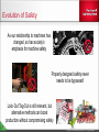
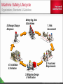
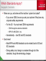
T60 - Integrated Safety with Kinetix® and PowerFlex® drives PUBLIC PUBLIC - 5058-CO900G Copyright © 2014 Rockwell Automation, Inc. All Rights Reserved. Agenda Introduction Machine Safety Lifecycle Motor Safety Drive Safety Tools & Services PUBLIC Copyright © 2014 Rockwell Automation, Inc. All Rights Reserved. 2 Definition of Safety Safety Freedom from unacceptable risk Functional Safety Part of the safety of the machine and the machine control system which depends on the correct functioning of: the safety related electrical control system other technology safety-related systems external risk reduction facilities PUBLIC Copyright © 2014 Rockwell Automation, Inc. All Rights Reserved. 3 Evolution of Safety As our relationship to machines has changed, so has society’s emphasis for machine safety Properly designed safety never needs to be bypassed! Lock-Out Tag-Out is still relevant, but alternative methods can boost production without compromising safety PUBLIC Copyright © 2014 Rockwell Automation, Inc. All Rights Reserved. 4 Machine Safety Lifecycle Organizations, Standards & Guidelines 5. Manage Change & Improve Safety Org, Stds & Guidelines 1. Risk Assessment 2. Functional Requirements 4. Installation & Validation 3. Mitigation Design & Verification PUBLIC Copyright © 2014 Rockwell Automation, Inc. All Rights Reserved. 5 Safety Organizations PUBLIC Copyright © 2014 Rockwell Automation, Inc. All Rights Reserved. 6 Which Standards Apply? Geographic Constraints Where are you, and where will the machine / system be located? If you are an OEM, be sure you ask your customer if they have any corporate safety requirements For the US - You must meet OSHA requirements OSHA recognizes consensus standards NFPA 79, ANSI Z244.1, etc. Internationally – Use ISO and IEC standards Good news! Most NFPA and ANSI standards can be related back to ISO and IEC standards Strong safety circuit design is consistent through all of the standards, though the terminology changes PUBLIC Copyright © 2014 Rockwell Automation, Inc. All Rights Reserved. Organization of Standards All functional safety standards are used to demonstrate compliance to global, regional and sometimes, national legal requirements Three types of Standards “A” Standards basic concepts principles for design general aspects “B” Standards B1 - safety distances, surface temps, noise B2 - components or devices “C” Standards vertical standards covering a single type of machine or group of machines. Use A and B standards to create C standards. PUBLIC Copyright © 2014 Rockwell Automation, Inc. All Rights Reserved. 8 Type A & Type B Standards North America ANSI B11.0 General Requirements and Risk Assessment ANSI B11.19 Performance Criteria for Safeguarding These two standards can get you most of the way with most safety applications in North America These are not recognized by the international community These standards do recognize the international community PUBLIC Copyright © 2014 Rockwell Automation, Inc. All Rights Reserved. 9 Type A & Type B Standards International ISO 12100 Safety of Machinery – General Principles for Design – Risk Assessment and Risk Reduction ISO 13849-1 Safety of Machinery – Safety Related Parts of Control Systems Part 1: General Principles for Design Replaced EN 954 in 2008 Simple devices, including electromechanical devices Common Terms: Categories (structure), Diagnostic Coverage (DC), Performance Levels (PL), Probability of Dangerous Failure per Hour (PFHD) PUBLIC Copyright © 2014 Rockwell Automation, Inc. All Rights Reserved. 10 Going Between Standards ANSI B11.19 & ISO 13849-1 While the requirements of control reliability are not directly comparable to the requirements of ISO 13849-1 (1999) or EN/ISO 13849-1 (2008), for the purposes of this standard, complying with Category 3 or 4 and/or Performance Level ―d or ―e, at a minimum, will satisfy the requirements of control reliability. Other Categories and Performance Levels per EN/ISO 13849-1, and Safety Integrity Levels (SILs) per IEC 61508 and IEC 62061 can also satisfy the requirements of this sub-clause depending on the design, construction, fault exclusions, installation, and maintenance of the safety-related function and a documented risk assessment. Right out of ANSI B11.19, E6.1 PUBLIC Copyright © 2014 Rockwell Automation, Inc. All Rights Reserved. 11 Summary of Standards Standards are there to help you by taking the guesswork out of your safety system design Use Type C standards when you can, otherwise use Type A & Type B Don’t be afraid to ask for help to understand them There are a lot of good interpretations online My recommended “desert island” standards: ANSI B11.0 / ANSI B11.TR3 or ISO 12100 ANSI B11.19 ISO 13849-1 & -2 IEC 60204-1 or NFPA 79 Use the standards to your advantage! PUBLIC Copyright © 2014 Rockwell Automation, Inc. All Rights Reserved. 12 Principles of Risk Assessments Risk Reduction Hierarchy of Protective Measures Inherently safe design Fixed guards Complementary protective measures Awareness (signs, signals, user manual) Personal protective equipment Some can be implemented by the machine builder Some rely on the end user’s organization PUBLIC Copyright © 2014 Rockwell Automation, Inc. All Rights Reserved. 13 Performing Risk Assessments Risk How Bad? How Often? Consequences Frequency How Likely? Chances Important to remember: What is the operating mode? Who is interacting with the machine? When in the lifecycle is this activity? What has already been done for protection? PUBLIC Copyright © 2014 Rockwell Automation, Inc. All Rights Reserved. 14 Functional Requirements Basic Concepts Functional Safety Specifications outline how a safety system responds from system inputs to control system outputs Functional safety specifications should address the following items: All modes of operation (Auto/Manual/Jog) All machine interactions (Jam removal/Cleaning/Set-up/Adjustment) Speed control and monitoring (Safe-speed/Safe-stop/etc.) Drive control (Braking/Accel/Decel) Special safety functions (Blanking/Muting/Zone Control) Keep them as simple as possible! PUBLIC Copyright © 2014 Rockwell Automation, Inc. All Rights Reserved. 15 Functional Requirements Basic Concepts Safety functions should always be written as Input – Interlocks, Sensors, E-stops, Light Curtains Logic – Safety Logic Relays, Safety Controllers Output – Contactors, Drives Below is an example of a simple Functional Safety System using a simple door interlock, a safety relay and safety contactors Input PUBLIC Logic Output Copyright © 2014 Rockwell Automation, Inc. All Rights Reserved. 16 Mitigation Design & Verification Basic Concepts Mitigation Design Which products are used How components are wired Where they are placed on the machine Code is written Verification Determine if the implementation meets the requirements Perform PL or SIL calculations at this time SISTEMA can be used when ISO 13849-1 is the standard to verify PUBLIC Copyright © 2014 Rockwell Automation, Inc. All Rights Reserved. 17 Mitigation Design & Verification SISTEMA for ISO 13849-1 Developed and maintained by a neutral and well-respected organization specializing in Functional Safety Simplified entry of safety related reliability information Vendor libraries reduce work to find critical data Reduce risk of mistakes in calculations Graphical view of safety functions Automatic report generation for faster documentation PUBLIC Copyright © 2014 Rockwell Automation, Inc. All Rights Reserved. 18 Installation & Validation Basic Concepts Follow through with the Mitigation Design Induce faults to validate system Use ISO 13849-2 for techniques, such as Table D.9 shown below PUBLIC Copyright © 2014 Rockwell Automation, Inc. All Rights Reserved. 19 Manage Change & Improve Basic Concepts OEMs Maintain designs to latest standards Perform Risk Assessments whenever designs are improved Add value through documentation Look for feedback from customers PUBLIC End Users Maintain designs to latest standards Perform Risk Assessments whenever designs are improved Expect documentation from OEMs Thoroughly document any changes from original machines Provide feedback to OEMs and governing bodies Copyright © 2014 Rockwell Automation, Inc. All Rights Reserved. 20 Machine Safety Lifecycle Organizations, Standards & Guidelines 5. Manage Change & Improve Safety Org, Stds & Guidelines 1. Risk Assessment 2. Functional Requirements 4. Installation & Validation 3. Mitigation Design & Verification PUBLIC Copyright © 2014 Rockwell Automation, Inc. All Rights Reserved. 21 Agenda Introduction Machine Safety Lifecycle Motor / Drive Safety Drive Safety Tools & Services PUBLIC Copyright © 2014 Rockwell Automation, Inc. All Rights Reserved. 22 AC Motor Safety Basic Concepts and Contactors Motors create some of the most common hazards on a machine Removal of torque producing power is the only method of safe control for motors Dual contactors are the traditional method for safe removal of motor power Contactors must be oversized to increase life and reduce chances of welding Lots of additional wiring PUBLIC Copyright © 2014 Rockwell Automation, Inc. All Rights Reserved. 23 Drive Safety - External Safe Torque-off Maximum amount of panel space required Multiple output contactors required for Cat 3 & 4 Maximum amount of installation/down time Tedious wiring Work increases with desired Category level Contactor welding may occur Lowest level of system reliability No Diagnostics Equipment required: Power wiring - $$$ Control wiring - $$$ Labor - $$$ PUBLIC 1769-L30ER CompactLogix™ 1 MB EtherNet/IP Controller 1769-IQ16 CompactLogix™ 16 Pt 24VDC D/I Module 1769-OB8 CompactLogix™ 8 Pt 24VDC D/O Module 1769-OF4VI CompactLogix™ 4 Pt A/O VoltageModule (3) 25A-D6P0N104 3HP PowerFlex® 523 AC Drive (6) 100S-C12D14BC 12 A Safety Contactor (3) 440R-D22R2 Guardmaster® Dual Input Safety Relay 30 control terminations for contactors, 4 safety input terminations, 18 I/O terminations for drives at $25/termination 36 extra power terminations for contactors Copyright © 2014 Rockwell Automation, Inc. All Rights Reserved. 24 Drive Safety - Safe Torque-off Remove torque by preventing the Inverter from synchronized switching Gate Control Circuitry creates waveforms to Inverter By disabling the Gate Control Circuitry, the Inverter cannot create torque at the motor Safety Control removes signals to Enable and Power of the Gate Control Circuitry Components have excellent reliability in a dual channel configuration PUBLIC Copyright © 2014 Rockwell Automation, Inc. All Rights Reserved. 25 Drive Safety – Hardwired Safe Torque-off Low level of panel space required Diagnostics: Basic fault information – Drive detects something is wrong, 440R also reports faults in components but reasons for safety demand require further investigation. Moderate amount of installation time Significantly improved level of reliability No contactors required Fewer opportunities for installation error Equipment required: PUBLIC 1769-L30ER CompactLogix™ 1 MB EtherNet/IP Controller (3) 25B-D6P0N104 PowerFlex® 525 AC Drives 1783 – BMS06SL Stratix™ 5700 6 Port Managed Switch 1734-AENTR POINT I/O™ Dual Port Network Adaptor 1734-IB8 24V DC 8 Channel Sink Input Module 1734-OB4 24V DC 4 Channel Source Output Module 440R-ENETR GSR Ethernet Interface 440R-D22R2 Guardmaster® Dual Input Safety Relay 8 safety terminations/4 safety input terminations at $25/termination Copyright © 2014 Rockwell Automation, Inc. All Rights Reserved. 26 Drive Safety Functions Safe Torque-off – Hardwired vs Integrated Hardwired Safety • Drive based monitoring • Safety relay for input devices • Discrete safety wiring Integrated Safety • Controller based monitoring • Guard Point I/O input devices • Communication via EtherNet/IP PUBLIC Copyright © 2014 Rockwell Automation, Inc. All Rights Reserved. 27 Drive Safety – Integrated Safe Torque-off Advanced level of diagnostics: Specific information on what component faulted / experienced safety demand and why Lowest level of panel space required No contactors No safety relays Lowest amount of installation time No bothering with small terminals Fewer user manuals to read Low opportunity for wiring error Highest level of reliability Only EtherNet/IP cable required Equipment required: PUBLIC 1769-L30ERMS Compact GuardLogix® Controller (3) 25C-D6P0N104 3HP PowerFlex® 527 AC Drive 1734-AENTR POINT I/O™ Dual Port Network Adaptor 1734-IB8S 8 Channel Safety Sinking Input Module 1734-IB8 24V DC 8 Channel Sink Input Module 1734-OB4 24V DC 4 Channel Source Output Module Copyright © 2014 Rockwell Automation, Inc. All Rights Reserved. 28 Drive Safety Functions Integrated Safe Torque-off Safety Message Producer to Consumer Data A Mode CRC-A Data Section Normal data Inverted data Data B CRC-B Time_Stamp CRC Time Stamp Section > Duality > Diagnostics > Diversity Capable of SIL3 / PLe Independent of network media Wired and wireless Works across many different networks A B Output A Output B STO STO EtherNet/IP CIP Safety Packet provides Duality, Diagnostics and Diversity! PUBLIC Copyright © 2014 Rockwell Automation, Inc. All Rights Reserved. Agenda Introduction Machine Safety Lifecycle Motor / Drive Safety Integrated Safety Tools & Services PUBLIC Copyright © 2014 Rockwell Automation, Inc. All Rights Reserved. 30 Integrated Safety on EtherNet/IP Flexibility with standard connection configurations PUBLIC Copyright © 2014 Rockwell Automation, Inc. All Rights Reserved. 31 Integrated Safety on EtherNet/IP Integrated Safety Enhances Machine Performance and Flexibility PUBLIC Copyright © 2014 Rockwell Automation, Inc. All Rights Reserved. 32 Application Example #1: GuardLogix® for Safety and Motion Control Zone 2 Zone 1 Zone 1 Zone 2 Zone 2 Zone 2 GuardLogix® allows machine flexibility for Motion and Safety PUBLIC Copyright © 2014 Rockwell Automation, Inc. All Rights Reserved. Safety Zoning in Logix Designer Zone 1 Zone 2 Zone 1 • • • Machine safety is configured in the safety task of Logix Designer. Safety connections made through EtherNet/IP. No additional wiring is required. Zone 1 Zone 2 Zone 2 34 Programmatically change the safety zones in Logix Designer PUBLIC Copyright © 2014 Rockwell Automation, Inc. All Rights Reserved. Safety Zoning in Logix Designer Zone 1 Zone 1 • • • • Machine safety is configured in the safety task of Logix Designer. Cut/paste Axis from one zone to another. Safety connection to the drive via EtherNet/IP. No additional wiring is required. Zone 2 Zone 1 Zone 2 Zone 2 35 Programmatically change the safety zones in Logix Designer PUBLIC Copyright © 2014 Rockwell Automation, Inc. All Rights Reserved. Application Example #1: GuardLogix® for Safety and Motion Control Zone 1 Zone 2 Zone 2 Machine flexibility for modular design, configuration and safety zoning PUBLIC Copyright © 2014 Rockwell Automation, Inc. All Rights Reserved. Application Example #2: GuardLogix® for Safety and CompactLogix™ for Motion Zone 1 Zone 2 Zone 3 Machine flexibility with separated control for Motion and Safety PUBLIC Copyright © 2014 Rockwell Automation, Inc. All Rights Reserved. Safety Reaction Time Explanation Hardwired Safety Light Curtain vs Light Curtain Light Curtain 1 Light curtain MSR input MSR (delayed) output 2 Guard Point input 3 4 Report to safety controller 5 Report STO to Drive 6 Drive STO Drive STO Safety task processing Integrated Safety Drive reaction time 10ms HW Drive reaction time 10ms 0 ms Integrated Safety 1 2 3 4 1 2 3 4 5 6 Use Safety reaction time tool to calculate system reaction time. PUBLIC Copyright © 2014 Rockwell Automation, Inc. All Rights Reserved. Safety Comparison Drive Based vs Integrated Drive Based Integrated Safety Configuration Specific to each device Unified in controller Wiring to Drive Often intensive wiring Reduced or eliminated Diagnostics Limited Detailed Integration Very little controller integration Seamlessly part of controller Maintenance Manual operation for replacement Automatic device configuration Application Space Only for specific problems Easily customized for anything Code Validation Must be repeated every time Simplified through code re-use Increasing customer value by integrating safety into the architecture. PUBLIC Copyright © 2014 Rockwell Automation, Inc. All Rights Reserved. 39 Integrated Safety Features and Benefits Reduce System Cost Perform SIL3 PLe Safe Torque-off safety functions over EtherNet/IP connection. Reduction in wiring of safety circuit. Fewer number of components required. Safety system validation through code reuse. Reduction in cabinet space requirements. Ease of Use Complete project integration in Logix Designer of control, safety and motion. Increased flexibility and modularity of system design and safety zoning. Detailed diagnostics to assist in commissioning and troubleshooting safety related faults. Safety zone configuration change without changing hardware. Integrated Safety Enhances Machine Performance PUBLIC Copyright © 2014 Rockwell Automation, Inc. All Rights Reserved. Common User Experience for Safety PowerFlex® 527 Kinetix® 5500 Integrated Motion and Safety configuration is identical in Logix Designer PUBLIC Copyright © 2014 Rockwell Automation, Inc. All Rights Reserved. 41 Logix Designer Configuration Complete and easy configuration for safety with Logix Designer. PUBLIC Copyright © 2014 Rockwell Automation, Inc. All Rights Reserved. Safe Torque-off Certification Kinetix® 5500 and PowerFlex® 527 TÜV Rheinland Approved Integrated safety with EtherNet/IP PLe, CAT3 per ISO 13849-1 SIL3 per IEC EN 61508, EN 62061 and EN 61800-5-2 Stop Category 0, EN 60204 Stop Category 0 Speed Stopping Time Time Motor Power Coast Time Increased safety rating using Kinetix® 5500 with Integrated Safety. PUBLIC Copyright © 2014 Rockwell Automation, Inc. All Rights Reserved. 43 Drive Safety - Diagnostics Diagnostics Contactors Only Diagnostics Contemporary Drive PUBLIC Diagnostics Traditional Drive Diagnostics Diagnostics Integrated Safety Drive Copyright © 2014 Rockwell Automation, Inc. All Rights Reserved. 44 Drive Safety Functions Reset Function & Feedback Circuits Network integration gives access to the drive status Apply these to Indicator Lights or HMI screens for faster troubleshooting PUBLIC Copyright © 2014 Rockwell Automation, Inc. All Rights Reserved. 45 Agenda Introduction Machine Safety Lifecycle Motor / Drive Safety Integrated Safety Tools & Services PUBLIC Copyright © 2014 Rockwell Automation, Inc. All Rights Reserved. 46 Rockwell Automation® Safety Tools Safety Return-On-Investment Tool Find out how to quantify the savings and productivity gains from safety investments. The Rockwell Automation® Safety Return-OnInvestment Tool accounts for improved safety, reduced claims, improved productivity, and other issues unique to safety applications. Safety Functions SAB Connected Components BB Safety Functions Program The Safety Functions Program is building block approach to designing safety systems. Each building block has a complete documentation package that includes a description of each safety function, an electrical schematic, a bill of material, a SISTEMA verification calculation and a verification and validation plan. Safety Automation Builder The Safety Automation Builder software package that allows users to import images of their machines. Users can identify hazardous access points and the associated hazards in order to develop a list of safety products that will be used to mitigate the risk. This gives the customer a complete drawing, a bill of material and SISTEMA calculation. Safety Connected Components Building Blocks The Connected Components Building Blocks provide users with pre-designed safety solutions that have panel drawings, wiring diagrams, programs, HMI screens and start-up manuals make the design and integration of safety systems quick and easy. Safety Solutions Toolkit Safety Solutions Toolkit The Safety Solutions Toolkit is a tool that presents all safety-related product launches, presentations, videos & animations, literature, event archives, and many other additional resources that the Rockwell Automation® Safety Solutions program provides. Safety Accelerator Toolkit Safety Accelerator Toolkit The Safety Accelerator Toolkit provides easy to use system design, programming, and diagnostic tools to assist you in the rapid development and deployment of your safety systems using GuardLogix®, Compact GuardLogix®, or SmartGuard™ 600 Controllers, Guard I/O™, and Safety Devices. The toolkit includes a risk assessment and system design guide, hardware selection guide, CAD drawings, safety logic routines, and operator status and diagnostic faceplates. Pro-Safe Builder Pro-Safe Trapped Key Builder The Pro-safe Trapped Key Builder tool allows you to build safety solutions using a broad range of trapped key switches and devices that can isolate pneumatic, hydraulic and electrical sources in a systematic repeatable process. Pro-safe builder is linked to ProposalWorks™ to allow users to generate complete Bills of Materials (BOM). PUBLIC Copyright © 2014 Rockwell Automation, Inc. All Rights Reserved. 47 Safety Function Library Overview “Building Blocks” approach to safety Combine blocks together for more complex functions Available for GuardLogix® controller or GuardMaster relay solutions Each one includes: System descriptions of operations Parts lists Electrical drawings SISTEMA calculations Verification & Validation plans PUBLIC Copyright © 2014 Rockwell Automation, Inc. All Rights Reserved. 48 Safety Automation Builder Overview Use Safety Automation Builder to: Layout machine hazards and access points Define safety functions and select safety products Export data to SISTEMA for analysis* Outputs of Safety Automation Builder include: Bill of Material Conceptual safety layout drawings SISTEMA project files* * Safety Automation Builder and SISTEMA tools must be used in conjunction with each other to provide this output PUBLIC Copyright © 2014 Rockwell Automation, Inc. All Rights Reserved. 49 Safety Accelerator Toolkit Overview Details the integration of multiple safety functions Includes importable wiring diagrams, logic, and HMI files Designed for use with programmable safety controllers, such as GuardLogix® and SmartGuard™ 600 Available on DVD or as a download from the web PUBLIC Copyright © 2014 Rockwell Automation, Inc. All Rights Reserved. 50 Rockwell Automation® Safety Services START Safety System Implementation Safety System Requirements • Consulting Services • Safety Summits to Drive Process • LOTO Consulting • Safety Circuit Design & Review • Safety Distance Calculations • Control Reliable Safety Designs • Safety Integration Services Safety System Validation • Validation Testing / Documentation • Conformity Audits Risk / Hazard Assessment • Conformance Audits • Risk Mitigation Consulting • Hazard Assessment • Risk Assessment • Safety Audit • SIL / Category Calculations PUBLIC Maintain & Improve Safety System • Training Services • Preventive Maintenance Programs • LOTO Consulting Copyright © 2014 Rockwell Automation, Inc. All Rights Reserved. 51 Safebook 4 PUBLIC Copyright © 2014 Rockwell Automation, Inc. All Rights Reserved. 52 Machine Safety Resources ANSI – American National Standards Institute www.ansi.org Explanation and Interpretation of Standards from Rockwell Automation® www.ab.com → Product Catalogs → Safety Products → Principles, Standards and Implementation → Standards Information on Rockwell Automation® Safety Solutions and Services www.rockwellautomation.com → Solutions & Services → Safety Solutions Safety Functions, User Manuals, Safebook 4, and more… literature.rockwellautomation.com Talk to Your Distributor Specialists and Rockwell Automation® Specialists! PUBLIC Copyright © 2014 Rockwell Automation, Inc. All Rights Reserved. 53