1
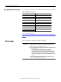
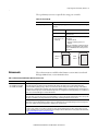
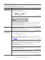
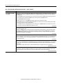
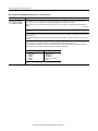
Release Notes CompactLogix 5370 L3 Controllers, Revision 20 Catalog Numbers 1769-L30ER, 1769-L30ER-NSE, 1769-L30ERM, 1769-L33ER, 1769-L33ERM, 1769-L36ERM About This Publication Topic Page Compatible Software Versions 2 Before You Begin 2 Enhancements 3 Corrected Anomalies 4 Known Anomalies 5 Restrictions 13 Install the Controller Revision 16 Additional Resources 16 This publication describes enhancements, known anomalies, and restrictions for CompactLogix™ 5370 L3 controllers, firmware revisions 20.011…20.013. Information that has been added or changed since the last revision of this publication is indicated by a change bar as shown to the side of this paragraph. In addition to information specific to the most recent firmware revision, the information from previous minor revisions is retained in these release notes. We strongly recommend that you review the information provided regarding previous firmware revisions. We recommend that you do so because, if you are upgrading your firmware through multiple previous revisions, all of the information specific to all of the revisions is applicable. For example, if you need to upgrade your 1769-L30ER controller from revision 20.011…20.012, all of the information specific to revisions 20.011 and 20.012 is applicable. 2 CompactLogix 5370 L3 Controllers, Revision 20 Compatible Software Versions To use firmware revision 20.013, these minimum software versions are required. Table 1 - Compatible Software Versions Software Required Software Version, Min. Compare Tool 3.20.02 ControlFLASH 11.00.00 FactoryTalk AssetCentre 4.00.00 (CPR 9, SR3) FactoryTalk Services Platform 2.50.00 (CPR 9, SR5) FactoryTalk Activation 3.50.00 (CPR 9, SR5) RSLinx Classic 2.59.01 (CPR 9, SR5) RSLinx Enterprise 5.50.04 (CPR 9, SR5) RSLogix 5000 20.01.00 (CPR 9, SR5) RSNetWorx for DeviceNet 11.00.00 (CPR 9, SR5) RSNetWorx for EtherNet/IP For system requirements, go to http://www.rockwellautomation.com/rockwellsoftware/design/rslogix5000/sys req.html. Before You Begin Before you upgrade your firmware, consider the following. IMPORTANT Loss of communication or power during a controller firmware upgrade can result in the controller rejecting the new firmware. Upon the rejection of new firmware, the controller reverts to the out-of-the-box firmware revision: • If the controller firmware upgrade fails and the OK status indicator flashes red, take these corrective actions: – Cycle controller power and attempt the firmware upgrade again. – If, after attempting another upgrade, the controller’s OK status indicator continues to flash red, cycle power and attempt another firmware upgrade. – If repeated attempts to upgrade the controller firmware continue to result in the OK status indicator flashing red, contact Rockwell Automation Technical Support. • If the controller firmware upgrade fails and the OK status indicator is solid red, contact Rockwell Automation Technical Support. Rockwell Automation Publication 1769-RN020C-EN-P - November 2012 CompactLogix 5370 L3 Controllers, Revision 20 3 These preliminary actions are required before using your controller. Table 2 - Before You Begin If Then You are updating a controller Before you begin updating your controller, check the status of your Secure Digital (SD) card. If your SD card is Then Unlocked You can successfully upgrade the firmware to the intended revision. Locked and the Load Image option is set to On Power Up You should complete these steps before beginning the upgrade: • Unlock the SD card. • Change the Load Image option to User Initiated. If the card is locked when you attempt to upgrade the firmware, the upgrade fails and the controller reverts to the firmware revision already stored on the SD card. Unlocked Position Locked Position These enhancements are available when firmware revision 20.011 is used with RSLogix 5000 software, version 20.00.00 or later. Enhancements Table 3 - Enhancements with Firmware Revision 20.011 or Later Cat. No. Description 1769-L30ER, 1769-L30ERM, 1769-L30ER-NSE, 1769-L33ER, 1769-L33ERM, 1769-L36ERM Automatic Device Configuration for Drives This feature supports the automatic device replacement functionality for drives. This makes it easier to perform quick, efficient drive replacement without requiring any laptop, software, or user intervention aside from wiring in the new drive and setting a network address. Previously, device configuration data for PowerFlex® drives was kept in the ACD file and had to be manually managed via the AOP of the device. Now, when a module is replaced, the controller will automatically send it to the configuration data. Always supported by Sercos and CIP motion drives. Version 20 extends ADC support to the PowerFlex 755 drives. Electronic Data Sheet AOP This feature allows select devices that have properly configured EDS sheets to integrate directly with Logix without the need for a device profile. This improves the flexibility of the Integrated Architecture™ by providing a richer integrated experience to more devices. Finding/Adding Devices to the Logix Tree Enhancements to the Select Module dialog box make it easier to use and find devices. The Select Module dialog box now shows all registered devices. It also includes new string and category filters, a wildcard search, and a favorites list. Security To enhance system and device-level security in systems that use our products, Rockwell Automation prescribes validated, defense-in-depth measures and design practices to enhance system and device-level security. For the latest information on security solutions and enhancements, visit http://www.rockwellautomation.com/solutions/security. Rockwell Automation Publication 1769-RN020C-EN-P - November 2012 4 CompactLogix 5370 L3 Controllers, Revision 20 Table 3 - Enhancements with Firmware Revision 20.011 or Later (continued) Cat. No. Description 1769-L30ER, 1769-L30ERM, 1769-L30ER-NSE, 1769-L33ER, 1769-L33ERM, 1769-L36ERM Security Authority Binding By checking the Require Matching Security Authority ID for Authentication and Authorization checkbox, you can bind the project file to a specific instance of the FactoryTalk Security directory. This lets you to verify the identity of the FactoryTalk Security directory that was used to authenticate and authorize users of a secured project file or secured controller. Once this is assigned, the project file or the controller containing the project file cannot be accessed by any users unless they are authenticated by this specific FactoryTalk Security directory. For more information, see the FactoryTalk Security System Configuration Guide, publication FTSEC-QS001. Change Detection When online with a controller, a 64-bit integer is displayed in the Audit Value dialog box. This Audit Value changes every time an event listed in the Changes To Detect configuration dialog box occurs. By inspecting this value, you can quickly determine if the behavior of a controller has been modified since the last time it was inspected. The Change Detection Audit Value is also exposed as a predefined tag by RSLinx Enterprise software for use in HMI displays or other applications. Additionally, it is included in every entry of the Controller Log. These anomalies have been corrected with these firmware revisions: • Corrected Anomalies with Firmware Revision 20.013 on page 4 • Corrected Anomalies with Firmware Revision 20.012 on page 4 Corrected Anomalies This anomaly has been corrected with firmware revision 20.013. Table 4 - Corrected Anomalies with Firmware Revision 20.013 Cat. No. Description 1769-L30ER, 1769-L30ER-NSE, 1769-L30ERM, 1769-L33ER, 1769-L33ERM, 1769-L36ERM CORRECTED: When using PowerFlex 750 series drives with firmware that supports Drives ADC (Automatic Drive Configuration) on power up, the controller can become stuck in the transition to Run mode. When stuck in the transition to Run mode, the application is not executing and the outputs are not being updated. For more information, refer to Knowledgebase document 493802. Lgx00135067, Lgx00130112 These anomalies have been corrected with firmware revision 20.012. Table 5 - Corrected Anomalies with Firmware Revision 20.012 Cat. No. Description 1769-L30ER, 1769-L30ERM, 1769-L30ER-NSE, 1769-L33ER, 1769-L33ERM, 1769-L36ERM CORRECTED: Safe State Values out does not work for 1794-IE4XOE2, 1794-OE12, and 1794-OE8H modules. IMPORTANT: This is an RSLogix 5000 software anomaly that requires version 20.01.00 software for the correction (PSA 2012-02-006). Lgx00126967, Lgx00126968, Lgx00127022 1769-L30ERM, 1769-L33ERM, 1769-L36ERM CORRECTED: A program with coordinated motion using the Merge All parameter set at low velocity can cause the controller to generate unintended motion. Lgx00124761, Lgx00119183 CORRECTED: Overshooting of an MCLM instruction while using an MCCD instruction can occur. In an application, the AccOverrideFactor cannot be changed, but an open list of path segments is processed. Lgx00124758, Lgx00124134 Rockwell Automation Publication 1769-RN020C-EN-P - November 2012 CompactLogix 5370 L3 Controllers, Revision 20 5 These anomalies have been identified with firmware revisions 20.011…20.013. Known Anomalies Table 6 - Known Anomalies with Firmware Revision 20.011…20.013 Cat. No. Description 1769-L30ER, 1769-L30ERM, 1769-L30ER-NSE, 1769-L33ER, 1769-L33ERM, 1769-L36ERM This anomaly occurs only in applications that use Integrated Motion on the EtherNet/IP network. An axis position register can roll back one motor revolution at powerup in the following conditions: • The axis uses a rotary feedback device. • The axis is configured for Cyclic Travel mode. • The axis windup point configuration is greater than the rotary feedback device’s hardware rollover point. • Either of the following scenarios occurs. Scenario #1 1. The axis stops close to the feedback device’s hardware rollover point. 2. The axis is powered down. 3. The axis moves across the hardware rollover point while powered down. 4. The axis is powered up again. Scenario #2 The axis moves beyond the cyclic windup point and power is cycled to the axis. An axis that uses a linear feedback device can also lose its absolute position if the axis is beyond half of the travel range of the feedback device and a power cycle occurred on the axis. Lgx00135078, Lgx00134920 If motion is initiated while a Motion Redefine Position (MRP) instruction is in the process of redefining an axis’ position on an absolute basis, the controller experiences a fault that is indicated by error code 85. Lgx00135082, Lgx00134472 An autotune does not take into consideration the Motion Polarity bit properly. The Motion Polarity bit is currently used by the controller when it generates motion commands to the drive, but when the autotune is done by the drive it does not use the bit. This could cause unexpected motion. Lgx00135084, Lgx00133874 Changes have been made to make recovery from a Soft Overtravel (SOT) condition on an AXIS_CIP_DRIVE easier. A SOT fault is currently defined such that the following conditions cause the fault: • The commanded position is on or beyond the SOT position. • The commanded motion is in the direction of the overtravel. Complete the following tasks to recover from the SOT fault. 1. Reset the SOT fault. 2. Enable the drive, if it is disabled. 3. Command motion in the opposite direction of the SOT position. These conditions can occur as a result of this anomaly correction: • The SOT fault will not immediately recur if the drive is enabled outside of the SOT position range. • No SOT exceptions will be generated when the axis is in the Stopped state. Lgx00135087, Lgx00129646 Rockwell Automation Publication 1769-RN020C-EN-P - November 2012 6 CompactLogix 5370 L3 Controllers, Revision 20 Table 6 - Known Anomalies with Firmware Revision 20.011…20.013 (continued) Cat. No. Description 1769-L30ER, 1769-L30ERM, 1769-L30ER-NSE, 1769-L33ER, 1769-L33ERM, 1769-L36ERM A combination of two application conditions may cause the System Task that manages the local CompactBus to stop functioning, resulting in a number of unexpected control system behaviors. The first application condition includes any of the following: • Your controller is sending MSG instructions to modules on the local CompactBus. • Your controller is sending MSG instructions across the CompactBus and through a network communication module to remote modules, for example, through a local 1769-SDN module to I/O modules on a DeviceNet network or a 1769-SM1 module to modules on a DPI/SCANport™ network. • Your controller is online with or browsing a DeviceNet network via a 1769-SDN scanner module via a controller connection, that is, through an EtherNet/IP communication module or USB cable. • Your controller’s project includes the maximum number of local expansion modules with each module’s RPI configured for a very fast rate. The second application condition is that you change the RPI rate for one or more Compact I/O™ modules in the control system via a project download or online change. When the anomaly occurs, the following events occur: • The Continuous Task no longer executes. • All User tasks, that is, Periodic and Event Tasks, configured at priority 6 and lower no longer execute. • All communication coming to the controller and going out from the controller stops. • I/O processing on the local CompactBus stops. In this case, outputs operate in their commanded state. • I/O connections over an EtherNet/IP network will continue to operate. However, the connections may no longer update, depending on where they are controlled in the application code. For example, if the I/O connections over an EtherNet/IP network are controlled via the Continuous Task, they no longer update. You can correct this anomaly by cycling power to the controller. Lgx00128715, Lgx00129742 Your controller might experience an anomaly when browsing the 1769 CompactBus or through a 1769-SDN on the 1769 CompactBus. Signs of the anomaly are as follows. 1. Browsing of the DeviceNet network will not occur. 2. Browsing of the local 1769 CompactBus will not occur. 3. Messages targeted to I/O modules on the local 1769 CompactBus will continuously error. 4. Messages to devices on DeviceNet will continuously error. Once the controller has entered this state, the only way to correct the anomalous behavior is to do the following. 1. Power down the controller. 2. Remove the battery. 3. Let the controller set for approximately five minutes. 4. Reconnect the battery. 5. Redownload the application. Lgx00117103, Lgx00129067 When using the Automatic Device Configuration (ADC) feature, the Logix controller ‘owns’ the configuration in the drive. Do not use the HIM or other external tools, such as DriveExplorer, to change drive parameters. Doing so may cause a sequence of events to occur that results in the connection between the controller and the drive to be dropped, and causes the controller to not be able to re-establish the connection. Consider using the Write Mask function (drive Parameter 888 - [Write Mask Cfg]) to prevent tools connected to ports other than the Embedded EtherNet/IP port from writing to the drive. Lgx00129012, Lgx00129165 Rockwell Automation Publication 1769-RN020C-EN-P - November 2012 CompactLogix 5370 L3 Controllers, Revision 20 7 Table 6 - Known Anomalies with Firmware Revision 20.011…20.013 (continued) Cat. No. Description 1769-L30ER, 1769-L30ERM, 1769-L30ER-NSE, 1769-L33ER, 1769-L33ERM, 1769-L36ERM Your controller might experience a major nonrecoverable fault if it uses an RSLogix 5000 project that requires most of the controller’s available memory and power is cycled to the controller. If the RSLogix 5000 project is so large that fewer than 25,000 bytes of controller memory remain free before power is cycled, the controller might experience this anomaly. Complete these steps to best determine how much controller memory the project uses. 1. If your controller is online, go offline. 2. Download the RSLogix 5000 project to the controller. 3. Cycle through all screens on each HMI device used in the application. Often, the inclusion of HMI devices, such as PanelView Plus terminals, in the project causes it to use a large portion of the controller’s memory. 4. Go online with the controller. 5. Access the Memory tab on the Controller Properties dialog box: – If your controller has 25,000 or more bytes of memory free, it should not experience this anomaly. – If your controller has fewer than 25,000 bytes of memory free, it is more likely to experience this anomaly after the next power cycle on the controller. If this anomaly occurs, clear the fault and download the project. Lgx00127414, Lgx00127450 Your controller’s domain name, an IP address setting, will not be retained if the name uses 48 characters and power is cycled to the controller. The maximum number of characters available in the domain name field is 48. Therefore, if you use all of the available characters in the domain name field and power is cycled to the controller, the domain name is not retained. This anomaly will not occur if the domain name field uses 47 or fewer characters. Lgx00126785, Lgx00126981 When the following conditions exist in your CompactLogix 5370 L3 control system, the controller may log a major recoverable fault, Type 2/Code 23: • The control system includes remote POINT I/O™ modules over an EtherNet/IP network. • Any of the POINT I/O modules are configured to Major Fault On Controller if Connection Fails While in Run Mode. • A power cycle occurs on the controller. To work around this anomaly, do not configure any remote POINT I/O modules over an EtherNet/IP network to Major Fault On Controller if Connection Fails While in Run Mode. Lgx00129095, Lgx00129057 In some conditions, an RSLogix 5000 project might not be restored or loaded from an installed SD card at controller powerup despite being configured to do so. This anomaly can occur when these conditions exist at powerup: • The controller is using firmware revision 1.x. Either of the following conditions result in the controller using firmware revision 1.x: – You apply power to the controller for the first time after taking it out of the box. – A disruption occurs during the process of upgrading controller firmware via the ControlFLASH utility. • The RSLogix 5000 project is configured with these parameters: – Load Image = On Corrupt Memory – Load Mode = Remote Run You can work around this anomaly by taking either of these actions before attempting to restore the RSLogix 5000 project for an SD card: • Upgrade the controller firmware revision to revision 20.011 or later. • Change the RSLogix 5000 project to Load Image = On Power Up. Lgx00126635, Lgx00125820 When using a 1747-AENTR SLC™ 500 EtherNet/IP Adapter and more than five modules in a remote SLC chassis connected to your CompactLogix 5370 L3 controller, the second download of a project to your controller causes the controller to lose communication with the remote SLC chassis. After losing communication with the remote SLC chassis, you also cannot communicate with the controller via the USB nor Ethernet port. You must disconnect the Ethernet cable from the 1747-AENTR adapter. After the Ethernet cable is disconnected from the 1747-AENTR adapter, you can re-establish communication to the controller. However, the controller contains no program at that point. You must re-download the program to the controller and then reconnect the Ethernet cable to the 1747-AENTR adapter to resume normal operations. Lgx00128819, Lgx00127668 Rockwell Automation Publication 1769-RN020C-EN-P - November 2012 8 CompactLogix 5370 L3 Controllers, Revision 20 Table 6 - Known Anomalies with Firmware Revision 20.011…20.013 (continued) Cat. No. Description 1769-L30ER, 1769-L30ERM, 1769-L30ER-NSE, 1769-L33ER, 1769-L33ERM, 1769-L36ERM When you browse the controller via RSLinx Classic software using the USB driver and click the + to open the EtherNet/IP network, the IP address for the controller will not indicate the configured values. Instead, the software shows an IP address of 0.0.0.0 as shown below. Lgx00128816, Lgx00128101 If a single module on the CompactBus experiences a fault or connection loss, all bits in the Fault word transition to 1. The Fault word bits for only the faulted module should transition to 1 and the Fault word bits for the other modules on the CompactBus remain 0. However, the Fault word bits for all modules transition to 1. Despite the Fault word bit transition to 1, the other modules on the CompactBus should be operating as expected. The controller incorrectly reports that the unaffected modules have experienced a fault. You must cycle power to the controller for the bits to return to the correct status, that is, 0, when all modules are in the running state. Lgx00126024, Lgx00125644 1769-L30ERM, 1769-L33ERM, 1769-L36ERM If your application includes Integrated Motion on an EtherNet/IP network and power is cycled to the drives in the project or to the controller, the controller may experience a major nonrecoverable fault. If your controller experiences a major nonrecoverable fault as a result of this anomaly, that is, power was cycled on a drive or the controller, clear the fault and then download the RSLogix 5000 project to the controller again. Lgx00126026, Lgx00125266 1769-L30ER, 1769-L30ERM, 1769-L30ER-NSE, 1769-L33ER, 1769-L33ERM, 1769-L36ERM PI function block appears to stop executing as the output does not change and no instruction faults are logged. If the PI instruction is being used in Linear mode, this floating-point equation is used to calculate the ITerm. WldInput + WldInput n – 1 Kp Wld ----------------------------------------------------------------- DeltaT + ITerm n – 1 2 Due to the use of the single-precision floating point values, it may be possible, depending on the values of WLD and KP, for the ITerm value to be small enough, less than 0.0000001, to be lost when adding to the ITermn-1. For more information regarding the PI instruction, see the Logix5000Controllers Process Control and Drives Instructions User Manual, publication 1756-RM006. Lgx00070832 Changes made to the Buffer Timeout value for FactoryTalk Alarms and Events subscribers do not take effect until the existing buffer has been deleted. The FactoryTalk alarm buffer (stored in Logix controller memory) is designed to persist through power cycles. If you change the Buffer Timeout value (via the Communication Setup dialog box in FactoryTalk View SE software), the controller does not use the new timeout value until the existing buffer is deleted and then recreated. To force recreation of this buffer, do one of the following: • Redownload the project to the controller. • Disconnect the FactoryTalk Alarms and Events subscriber and leave it disconnected until the existing timeout expires. Lgx00069461 The MinDurationPRE and MinDurationACC members of ALARM_ANALOG and ALARM_DIGITAL tags are defined as DINT (signed double integer) but they are treated as UDINT (unsigned double integer) by Logix firmware. This causes negative values of the tag members to be handled as large positive numbers when they should be handled as zero. Lgx00119996, Lgx00119981 When you accept edits in LD, ST, and FBD, the controller will log an ‘Online Edit’ entry in the controller log. Accepting edits in a SFC routine is done by performing a partial import, resulting in a ‘Transaction Commit’ entry in the controller log. This is confusing because you can select to mask both entries separately. Selecting only Online edits would cause the Audit Value to change only when FBD, ST, and LD edits are made. SFC online edits would change the Audit Value only if the ‘Partial Import Online Transaction Completed’ bit was set. Lgx00122528, Lgx00122622 Rockwell Automation Publication 1769-RN020C-EN-P - November 2012 CompactLogix 5370 L3 Controllers, Revision 20 9 Table 6 - Known Anomalies with Firmware Revision 20.011…20.013 (continued) Cat. No. Description 1769-L30ER, 1769-L30ERM, 1769-L30ER-NSE, 1769-L33ER, 1769-L33ERM, 1769-L36ERM In SFCs, when using time-limited actions in steps, if the program stays on a given step for greater than 24 days (2**32 ms) the timer’s accumulator (ACC) will roll over and the action body starts to execute again. The time-limited action initializes its timer when it starts (step is first scanned). On subsequent scans, it compares the timers PRE and ACC value. If ACC<PRE, the action body will execute. If ACC >=PRE, it is not executed. When the roll over occurs, the ACC, PRE, and the action body will again execute when it should not. Lgx00124689, Lgx00124697 The controller supports only three active reconfigure messages at a time. If more than three are triggered at a time, they will complete (DN bit will go high), but not all the modules will be reconfigured. For example, if you send five reconfiguration messages at the same time, three reconfigure messages will truly complete (DN bit will go high), and the I/O modules will be reconfigured. The other two reconfigure messages will indicate complete (DN bit will go high), but the I/O modules will not be reconfigured. In this case, the last two should have errored (ER bit), but do not. Lgx00125204, Lgx00124996 When launching RSLogix 5000 software, the Log On to FactoryTalk dialog box can be displayed. This dialog box can be seen when you do not have Administrator privileges on the personal computer and the current user does not exist in the FactoryTalk directory. If you cancel this dialog box, RSLogix 5000 software will not be launched. When the dialog box is displayed, entering the credentials for a user that has Administrator privileges on the personal computer will then allow RSLogix 5000 software to be launched. To avoid seeing this dialog box, you can add the current user or user group to the FactoryTalk directory. Follow these steps to add a user or user group to the FactoryTalk directory. 1. Launch the FactoryTalk Administration Console (available from the Start menu). 2. Select the Network directory when prompted. (You may need to provide credentials for a user with Administrator privileges in order to continue.) 3. To allow access for a particular user, navigate to Network\System\Users and Groups\Users, right-click the Users folder and choose New>Windows Linked User. 4. Click Add and provide the domain\logon name for the desired user. (You can click Check Names to verify that the name was found.) 5. To allow access for all authenticated users, navigate to Network\System\Users and Groups\User Groups, right-click the User Groups folder and choose New>Windows Linked User Group. 6. Click Add and type the name of the user group, Authenticated Users. The Log On to FactoryTalk dialog box can also display when using Remote Desktop to connect to the personal computer running RSLogix 5000 software. This is due to FactoryTalk Security not recognizing the computer name. To enable access through Remote Desktop for a specific computer, add the name of the computer initiating the Remote Desktop connection to the Network\System\Computers and Groups\Computers folder in the FactoryTalk Administration Console. To allow all computers to connect, follow these steps. 1. Open the FactoryTalk Administration Console and log in to the Network directory by using your domain credentials. 2. Navigate to Network\System\Security Policy. 3. In the Computer Policy Settings section, set Identify terminal server clients using the name to Server Computer. IMPORTANT: If Use single sign-on is set to disable in FactoryTalk software, then the Log On to FactoryTalk dialog box will be displayed each time RSLogix 5000 software is launched and proper user credentials must be entered in order to continue. (By default, ‘Use single sign-on’ is set to enable.) Lgx00124955 Rockwell Automation Publication 1769-RN020C-EN-P - November 2012 10 CompactLogix 5370 L3 Controllers, Revision 20 Table 6 - Known Anomalies with Firmware Revision 20.011…20.013 (continued) Cat. No. Description 1769-L30ER, 1769-L30ERM, 1769-L30ER-NSE, 1769-L33ER, 1769-L33ERM, 1769-L36ERM If the power to the controller is lost when the controller is writing a file to the SD card via a MSG instruction, the access can fail. The result of the failure is that the file or the file allocation table (FAT) can be corrupted on the SD card. Consequently, all future attempts to read from or write to the SD card can also fail. If your program is structured to attempt to access the SD card, it will repeatedly fail and experience a timeout condition on the operation. While these attempts are occurring, the controller does not service other message communication as expected, resulting in slower controller communication performance. IMPORTANT: As long as the corrupted file exists on the SD card, you cannot use the SD card in other controllers. You must first clear all files from the SD card before it can be used again. If you experience this anomaly, complete these steps to attempt to correct it. 1. Change your controller to Program mode. 2. Remove the SD card. 3. Delete the corrupted file from the card or format the card. 4. Re-install the SD card. 5. Re-attempt to write the file to the SD card via a MSG instruction. If you complete these steps and the issue persists, contact Rockwell Automation Technical Support. TIP: The life expectancy of flash media is dependent on the number of write cycles that are performed. Flash media controllers use wear leveling but you should avoid frequent writes. Avoiding frequent writes is particularly important when logging data. We recommend that you log data to a buffer in your controller’s memory and limit the number of times data is written to removable media. Lgx00124850, Lgx00124576 Your controller can experience a Module RPI Overlap minor fault (Type 03/Code 94) when you perform any of the following actions: • Download an RSLogix 5000 project to the controller. Typically, a project download results in this anomaly if the project includes modules with large I/O sizes, such as a 1769-SDN scanner module, or high numbers of I/O modules. • While the controller is online, you attempt to change the RPI value for an I/O module. • While the controller is online, you attempt to inhibit and then uninhibit an I/O connection. When your controller experiences a Module RPI Overlap minor fault as a result of these actions, use the Controller Properties dialog box to clear the fault. Lgx00125049, Lgx00124926, Lgx00124927 When a controller transmits unconnected MSG instructions over the CompactBus and through a 1769-SDN scanner module, the instruction execution time can be longer than expected. Slower execution times can cause some MSG instructions to timeout. This anomaly occurs when the MSG instruction is targeted at or through any of the following modules: • 1769-SDN scanner module • 1769-SM1 Compact I/O to DPI/SCANport module • 1769-SM2 Compact I/O DSI/Modbus communication module • ProSoft modules Lgx00124799, Lgx00122887, Lgx00124720 You must inhibit all controller connections to local expansion modules, including the 1769-SDN scanner module, before uploading a scanlist from, or downloading a scanlist to, a 1769-SDN scanner module. If you attempt to upload or download a scanlist without inhibiting connections to the local expansion modules, the scanlist upload or download can fail. To work around this anomaly, use one of the following options: • Change your RSLogix 5000 project to increase the controller’s available bandwidth and, thus, make processing communication requests easier. For example, if you slow RPI rates for local expansion modules or change user task timing and priorities, the controller is more likely to upload or download a scanlist successfully. • Access the 1769-SDN scanner module via the DeviceNet network, for example, through a 1784-U2DN USB-to-DeviceNet cable or 1788-EN2DN Ethernet-to-DeviceNet linking device, to upload or download a scanlist. Rockwell Automation Publication 1769-RN020C-EN-P - November 2012 CompactLogix 5370 L3 Controllers, Revision 20 11 Table 6 - Known Anomalies with Firmware Revision 20.011…20.013 (continued) Cat. No. Description 1769-L30ER, 1769-L30ERM, 1769-L30ER-NSE, 1769-L33ER, 1769-L33ERM, 1769-L36ERM You must inhibit all controller connections to local expansion modules, including the 1769-SDN scanner module, before updating firmware to a 1769-SDN scanner module. If you attempt a firmware update to a 1769-SDN scanner module without inhibiting the connections, the firmware update can timeout, rendering the scanner module inoperable. To work around this anomaly, use one of the following options. Option One 1. In a separate system, update the firmware revision on a replacement 1769-SDN scanner module to the desired revision. 2. Remove power from the CompactLogix 5370 L3 control system. 3. Replace the existing 1769-SDN scanner module with the updated scanner module. 4. Change the original RSLogix 5000 project so the 1769-SDN scanner module is configured with the new firmware revision. 5. Power the control system. 6. Download the original RSLogix 5000 project, updated with the new 1769-SDN scanner module firmware revision, to the CompactLogix 5370 L3 controller. Option Two 1. Download a new, blank RSLogix 5000 project to the CompactLogix 5370 L3 controller. 2. Update the firmware revision of the 1769-SDN scanner module. 3. Change the original RSLogix 5000 project so the 1769-SDN scanner module is configured with the new firmware revision. 4. Download the original RSLogix 5000 project, updated with the new 1769-SDN scanner module firmware revision, to the CompactLogix 5370 L3 controller. Option Three 1. Access the 1769-SDN scanner module via the DeviceNet network, for example, through a 1784-U2DN USB-to-DeviceNet cable or 1788-EN2DN Ethernet-to-DeviceNet linking device. 2. Update the firmware revision of the 1769-SDN scanner module. 3. Change the original RSLogix 5000 project so the 1769-SDN scanner module is configured with the new firmware revision. 4. Download the original RSLogix 5000 project, updated with the new 1769-SDN scanner module firmware revision, to the CompactLogix 5370 L3 controller. IMPORTANT: When using any of the options described above, consider the Electronic Keying configuration for the 1769-SDN scanner module in your RSLogix 5000 project and any impact the configuration choice might have on your control system operation. The controller does not correctly display the active ring supervisor on the Ring Statistics webpage available from the Diagnostics folder. The webpage displays the active ring supervisor IP address in reverse order. For example, an active ring supervisor using an IP address of 192.168.1.4 appears on the Ring Statistics webpage as 4.1.168.192. Lgx00125647, Lgx00125517 The controller’s Ethernet port settings, for example, the IP address or Subnet Mask, are always loaded from the SD card regardless of the Load Image parameter configuration on the Nonvolatile Memory Load/Store dialog box. Lgx00126022, Lgx00125674 When modifying the controller’s Ethernet configuration with RSLinx Classic software, you may experience a Module Configuration Invalid: Parameter error (16#0009). This anomaly occurs if you try to apply two network configuration changes without closing the Controller Properties dialog box between the changes. To work around this anomaly, close the Controller Properties dialog box after making every Ethernet configuration change in RSLinx Classic software. Lgx00126023, Lgx00125612 If the controller sends MSG instructions across the CompactBus through a 1769-SDN scanner module to nodes on a DeviceNet network, and a targeted node does not exist on the network, the .DN bit may be set for that MSG instruction when the .ER bit should be set. Lgx00126025, Lgx00125534 Rockwell Automation Publication 1769-RN020C-EN-P - November 2012 12 CompactLogix 5370 L3 Controllers, Revision 20 Table 6 - Known Anomalies with Firmware Revision 20.011…20.013 (continued) Cat. No. Description 1769-L30ERM, 1769-L33ERM, 1769-L36ERM Under some rare occurrences, if a Motion Axis Move (MAM) instruction with Merge Enabled is activated during the deceleration segment of an active MAM instruction then the new MAM instruction can overshoot its programmed endpoint. The occurrence of the overshoot depends on the following factors: • The original MAM instruction’s remaining travel distance at the time of the merge and the new MAM instruction’s remaining travel distance • The relationship of the decel jerk of the new MAM instruction to the decel jerk of the original MAM instruction • If the original MAM instruction is decelerating Typically, the overshoot does not occur. If either of the following conditions exist, you will avoid the overshoot: • The new MAM instruction is programmed with Merge Disabled. If there is no other motion active at the time of the merge, then the Merge Disable results in the same operation as the Merge Enable. • The new MAM instruction has a slightly higher jerk (in units/seconds3) than the original MAM instruction. You should note, though, lower value of jerk in % of time results in higher value of jerk (in units/seconds3). Lgx00078822 If a Motion Group Shutdown Reset (MGSR) instruction is executed while a Motion Group Shutdown (MGSD) is still executing, motion error #7, that is, Shutdown State Error, results. The purpose of an MGSR instruction is to bring an axis group out of the shutdown state. However, when the scenario described in the previous paragraph exists, the MGSR instruction is not executed because the shutdown procedure, initiated by the MGSD instruction, has precedence. Thus, the MGSR instruction generates motion error #7 because the shutdown procedure has not completed. The shutdown procedure must complete before any attempt to reset the shutdown. Lgx00095484 This anomaly occurs only in applications that use Integrated Motion on the EtherNet/IP network. With any coordinated move in a system that uses two or more Integrated Motion on the EtherNet/IP network axes, if one axis is disabled by using a Motion Servo Off (MSF) instruction, any remaining Integrated Motion on the EtherNet/IP network axes will generate an Excessive Velocity Error, that is, Drive Error S55. Lgx00105360 This anomaly occurs only in applications that use Integrated Motion on the EtherNet/IP network. When you create a new Integrated Motion on the EtherNet/IP network axis, the default value for Mechanical Brake Delay = 0. If you are using a motor with a brake on this axis and do not change the Mechanical Brake Delay value, the motor will not work properly when you attempt to execute motion. To work around this anomaly, make sure that you set the Mechanical Brake Delay to the appropriate value before executing motion. Lgx00113541, Lgx00107169 This anomaly occurs only in applications that use Integrated Motion on the EtherNet/IP network. Every time there is a Motion Servo Off (MSF) instruction/Motion Servo On (MSO) instruction cycle, the Position Trim value is added to the axis position. This change in axis position causes the axis to move unexpectedly by a distance equal to the Position Trim value. Lgx00113540, Lgx00108486 Rockwell Automation Publication 1769-RN020C-EN-P - November 2012 CompactLogix 5370 L3 Controllers, Revision 20 13 These restrictions exist with firmware revisions 20.011…20.013. Restrictions Table 7 - Restrictions with Firmware Revisions 20.011…20.013 Cat. No. Description 1769-L30ER, 1769-L30ERM, 1769-L30ER-NSE, 1769-L33ER, 1769-L33ERM, 1769-L36ERM Tasks are the basic scheduling mechanism for executing a program and are created as part of the project and program creation process. In addition to other internal tasks, the CompactLogix controllers have an internal task to provide communication with the 1769 I/O modules. This task executes periodically at the Requested Packet Interval (RPI) selected in the properties of the CompactBus. If the task has not completed before it is time to execute again, a task overlap occurs. This task overlap causes the packaged controller to declare a minor fault of Type = 6 (Task Overlap), Code = 4 (VA task). You can use various strategies to resolve minor faults due to task watchdog timeout and/or task overlap. For more information, see RSLogix 5000 Online Help ‘Identifying and Managing Tasks’. In the case of a minor fault caused by VA task overlap, increase the RPI until the overlap no longer occurs. • If you use a CE 6.0 Operating System PanelView Plus terminal in your CompactLogix 5370 L3 control system, you must upgrade to firmware upgrade package 6.10 for the controller to communicate with the terminal. This firmware upgrade file for package 6.10 is available at http://support.rockwellautomation.com/ControlFlash/FUWCom.asp. • If you use a CE 4.1 Operating System PanelView Plus terminal in your CompactLogix 5370 L3 control system, you must upgrade to firmware upgrade package 5.10.08 for the new CompactLogix 5370 L3 controller to communicate. The firmware upgrade file is available at http://support.rockwellautomation.com/ControlFlash/FUW.asp. For more information, see KnowledgeBase article #473017 - CompactLogix 5370 Controllers Compatibility with PanelView Plus. Lgx00127906 These are the Arithmetic State flags anomalies: • When dealing with Floating point numbers, the controller does not truncate denormalized values or -0.0…0.0. • For an integer divide, when the denominator is 0, the S:N and S:Z are not set. • For the MOD instruction, the S:V is not set if an overflow occurred during the calculation. Lgx00122480 The Logix CPU security tool does not work with V20 controllers. The RSLogix 5000 Clock Update tool does not support Windows 7 or Windows Server 2008 operating system. The Totalizer (TOT) instruction may not function properly when a project used with a 1756-L7x controller is converted to be used with a CompactLogix 5370 L3 controller and then downloaded to a CompactLogix 5370 L3 controller. This anomaly can occur under these conditions: • An RSLogix 5000 project is running on a ControlLogix controller, catalog numbers 1756-L7x, revision 18, with the TOT instruction in Run mode. • The project is uploaded and saved to a new file. • The new file is changed from the 1756-L7x controller, revision 18, to a CompactLogix 5370 L3 controller, revision 20. • The project is downloaded to the new CompactLogix 5370 L3 controller. • The project transitions to Run mode. Upon transitioning to Run mode, the TOT instruction’s output value is different from the last value generated when the same project was running on the first controller. To reset an invalid Totalizer value, set the ProgResetReq or OperResetReq to move the value of the instruction’s Reset input parameter to the instruction’s Total output parameter. Repeat this task once more to move the invalid value out of the instruction’s OldTotal output parameter. Lgx00114767, Lgx00114731 Rockwell Automation Publication 1769-RN020C-EN-P - November 2012 14 CompactLogix 5370 L3 Controllers, Revision 20 Table 7 - Restrictions with Firmware Revisions 20.011…20.013 (continued) Cat. No. Description 1769-L30ER, 1769-L30ERM, 1769-L30ER-NSE, 1769-L33ER, 1769-L33ERM, 1769-L36ERM If the controller is connected to a computer via a USB cable and the computer is restarted while the cable remains connected, you must disconnect and reconnect the cable between the controller and computer after the computer restart is complete. Failure to disconnect and reconnect the cable results in a failure of the computer to recognize the controller when browsing in RSLinx Classic software. Lgx00122143 The end cap must be attached to the CompactLogix 5370 L3 control system before you update the firmware to a controller or I/O module on the 1769 bus. If a 1769 I/O module fault occurs, you must cycle power to the controller after clearing the major fault. I/O communication is not restored until after the power cycle. Never use the fault handling routine to clear local I/O faults. Clear local I/O faults manually on a per instance basis, and then cycle power to the controller. With RSLogix 5000 software, version 20.01.00, or later, and controller firmware revisions 20.012 or 20.011, the Fault/Program states for Compact I/O modules are not supported and cannot be configured by using the Module Configuration dialog box. Because the CompactLogix system does not provide support for local modules to use the alternate outputs, do not configure the attributes or tags listed below. These tags are still created when you add the I/O modules to the configuration. For Digital Output Modules For Analog Output Modules • • • • • • • • • ProgToFaultEn ProgMode ProgValue FaultMode FaultValue CHxProgToFaultEn CHxProgMode CHxFaultMode Where CHx = the channel number Rockwell Automation Publication 1769-RN020C-EN-P - November 2012 CompactLogix 5370 L3 Controllers, Revision 20 15 Table 7 - Restrictions with Firmware Revisions 20.011…20.013 (continued) Cat. No. Description 1769-L30ER, 1769-L30ERM, 1769-L30ER-NSE, 1769-L33ER, 1769-L33ERM, 1769-L36ERM When you use some I/O modules in a CompactLogix 5370 L3 control system, they can cause the controller to fail its power-up sequence. When this occurs, the controller remains in a state with the OK status indicator solid red. If you use any of the modules listed below in your CompactLogix 5370 L3 control system, make sure you use the series and firmware revisions, or later, listed. Cat. No. 1769-ARM 1769-ASCII 1769-BOOLEAN 1769-HSC 1769-IA16 1769-IA8I 1769-IF16C 1769-IF16V 1769-IF4 1769-IF4FXOF2F 1769-IF4I 1769-IF4XOF2 1769-IF8 1769-IG16 1769-IM12 1769-IQ16 1769-IQ16F 1769-IQ32 1769-IQ6XOW4 1769-IR6 1769-IT6 1769-OA16 1769-OA8 1769-OB16 1769-OB16P 1769-OB32 1769-OB32T 1769-OB8 1769-OF2 1769-OF4 1769-OF4CI 1769-OF4VI 1769-OF8C 1769-OF8V 1769-OG16 1769-OV16 1769-OV32T 1769-OW16 1769-OW8 1769-OW8I 1769-SDN Series A A A A A A A A B A A A A A A A A A B A A A B B B A A A B A A A A A A B A A B B B Firmware Revision 3.1 2.001 1.2 1.1 3.1 3.1 1.2 1.2 2.1 1.2 1.2 1.1 1.1 3.1 3.1 3.1 3.1 3.1 3.1 3.1 2.2 3.1 3.1 3.1 3.1 3.1 3.1 3.1 2.1 1.1 2.1 2.1 2.1 2.1 3.1 3.1 3.1 3.1 3.1 3.1 2.2 Lgx00127867, Lgx00127768 Rockwell Automation Publication 1769-RN020C-EN-P - November 2012 16 CompactLogix 5370 L3 Controllers, Revision 20 Install the Controller Revision Install the Controller Revision To download the latest CompactLogix 5370 L3 controllers firmware revision, go to http://www.rockwellautomation.com/support/downloads and select your desired revision. Then, use the ControlFLASH utility to upgrade your controller. Alternatively, if you have installed RSLogix 5000 software, version 20, and related firmware, you may not need to complete the tasks described. The AutoFlash feature of RSLogix 5000 software detects if your controller firmware needs to be upgraded upon a program download to the controller. If a firmware upgrade is necessary, AutoFlash will initiate an upgrade. After you have completed your firmware upgrade, complete these steps to verify that the upgrade was successful. 1. Cycle power to the controller. 2. Go online with the controller and view controller properties. 3. Verify that the firmware revision listed matches the firmware to which you intended to upgrade. 4. If the controller’s firmware is not correct, initiate another firmware upgrade. For more information about errors when completing a ControlFLASH upgrade, see the ControlFLASH Firmware Upgrade Kit Quick Start, publication 1756-QS105. Additional Resources These documents contain additional information concerning related products from Rockwell Automation. Resource Description CompactLogix 5370 Controllers User Manual, publication 1769-UM021 Describes how to install, use and troubleshoot your CompactLogix 5370 controllers ControlFLASH Firmware Upgrade Kit Quick Start, publication 1756-QS105 Contains informations about firmware upgrades, installation instructions, and error messages You can view or download publications at http://www.rockwellautomation.com/literature/. To order paper copies of technical documentation, contact your local Allen-Bradley distributor or Rockwell Automation sales representative. Rockwell Automation Publication 1769-RN020C-EN-P - November 2012 CompactLogix 5370 L3 Controllers, Revision 20 17 Notes: Rockwell Automation Publication 1769-RN020C-EN-P - November 2012 Rockwell Automation Support Rockwell Automation provides technical information on the Web to assist you in using its products. At http://www.rockwellautomation.com/support, you can find technical manuals, technical and application notes, sample code and links to software service packs, and a MySupport feature that you can customize to make the best use of these tools. You can also visit our Knowledgebase at http://www.rockwellautomation.com/knowledgebase for FAQs, technical information, support chat and forums, software updates, and to sign up for product notification updates. For an additional level of technical phone support for installation, configuration, and troubleshooting, we offer TechConnectSM support programs. For more information, contact your local distributor or Rockwell Automation representative, or visit http://www.rockwellautomation.com/support/. Installation Assistance If you experience a problem within the first 24 hours of installation, review the information that is contained in this manual. You can contact Customer Support for initial help in getting your product up and running. United States or Canada 1.440.646.3434 Outside United States or Canada Use the Worldwide Locator at http://www.rockwellautomation.com/support/americas/phone_en.html, or contact your local Rockwell Automation representative. New Product Satisfaction Return Rockwell Automation tests all of its products to ensure that they are fully operational when shipped from the manufacturing facility. However, if your product is not functioning and needs to be returned, follow these procedures. United States Contact your distributor. You must provide a Customer Support case number (call the phone number above to obtain one) to your distributor to complete the return process. Outside United States Please contact your local Rockwell Automation representative for the return procedure. Documentation Feedback Your comments will help us serve your documentation needs better. If you have any suggestions on how to improve this document, complete this form, publication RA-DU002, available at http://www.rockwellautomation.com/literature/. Allen-Bradley, Compact I/O, CompactLogix, ControlFLASH, ControlLogix, FactoryTalk, Logix5000, PanelView, POINT I/O, Rockwell Software, Rockwell Automation, RSLinx, RSLogix, RSNetworx, SCANport, SLC, PowerFlex, and TechConnect are trademarks of Rockwell Automation, Inc. Trademarks not belonging to Rockwell Automation are property of their respective companies. Rockwell Otomasyon Ticaret A.Ş., Kar Plaza İş Merkezi E Blok Kat:6 34752 İçerenköy, İstanbul, Tel: +90 (216) 5698400 Publication 1769-RN020C-EN-P - November 2012 Supersedes Publication 1769-RN020B-EN-P - May 2012 PN-181236 Copyright © 2012 Rockwell Automation, Inc. All rights reserved. Printed in the U.S.A.