1
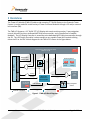
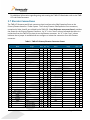
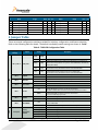
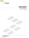
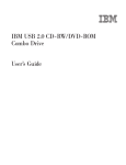
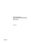
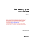
TWR-LCD
User’s Manual
Rev. 1.1
Freescale Semiconductor Inc.
Contents
1 Overview ......................................................................................................................................................3
2 Reference Documents ..............................................................................................................................4
3 Hardware Features ...................................................................................................................................4
3.1 Power Supply ....................................................................................................................................................................... 4
3.2 LCD Display / Controller ................................................................................................................................................. 5
3.2.1 Communication Mode ...................................................................................................................................................................... 5
3.2.2 MCU Selection ...................................................................................................................................................................................... 5
3.2.3 Resistive Touch Overlay .................................................................................................................................................................. 6
3.3 MicroSD Card........................................................................................................................................................................ 7
3.4 5-way Navigation Switch ................................................................................................................................................. 8
3.5 Mini-B USB Connection .................................................................................................................................................... 8
3.6 Bootloader ............................................................................................................................................................................. 9
3.6.1 Obtaining the S19 file........................................................................................................................................................................ 9
3.6.2 Using the Bootloader ........................................................................................................................................................................ 9
3.7 Elevator Connections ..................................................................................................................................................... 10
4 Jumper Table ........................................................................................................................................... 12
4.1 Mechanical Form Factor ............................................................................................................................................... 13
TWR-LCD User’s Manual
Page 2 of 13
1 Overview
The Tower LCD Module (TWR-LCD) adds a side mounting TFT QVGA Display to the Freescale Tower
System. It can be used with a wide variety of Tower Processor Modules through a SPI and/or external
bus interface (EBI).
The TWR-LCD features a 3.2” QVGA TFT LCD Display with touch sensitive overlay, 5-way navigation
control, MicroSD Card slot, dedicated MCF51JM microcontroller, and a Piezo Buzzer for audible
feedback. The LCD Display Controller is accessible to the dedicated MCF51JM microcontroller through
the SPI. The LCD Display Controller is also accessible to any capable Tower MCU module utilizing
either the SPI or the EBI. A block diagram for the TWR-LCD is shown in the figure below.
PWM
5.0V
SPI2
SPI1, IRQ, GPIO
I2C
Piezo
SPI0
Power Regulation
15.5V
3.3V
Backlight
Driver
Core
Voltage
PWM
LCD Display Controller
External Bus
Interface (EBI)
Resistive
Touch Panel
LCD Display
Tower Primary Side Expansion Ports
(Sides A and B)
Analog
Analog
mini-B USB
Recepticle
5.0V
External Connectors
SPI1, KBI, GPIO
MCF51JM
ColdFire® V1
Microcontroller
USB (DP/DN)
Interface Component
microSD
Card
Socket
5-Way Navigation
Switch
Freescale Device
Power
Figure 1 - TWR-LCD Block Diagram
TWR-LCD User’s Manual
Page 3 of 13
Figure 2 - Tower System with TWR-LCD
2 Reference Documents
The documents listed below should be referenced for more information on the Freescale Tower
system and the TWR-LCD. Refer to http://www.freescale.com/tower for the latest revision of all
Tower documentation.
TWR-LCD Schematics
TWR-LCD Quick Start Guide
Truly TFT2N0451-E LCD Module Specification
3 Hardware Features
This section provides more details about the features and functionality of the TWR-LCD.
3.1 Power Supply
The TWR-LCD can be powered as a standalone device from the Mini-B USB connector. The TWR-LCD
can also be powered from a source in an assembled Tower System via the 5.0V supply on the TWRELEV Side Expansion Port. When attached to a Tower Elevator board, it is required that the board be
externally powered from the Elevator board; additionally the USB connector on the TWR-LCD can still
be used to communicate over USB to the on-board MCF51JM MCU. On-board power regulation will
provide the necessary core voltage (3.3V) and backlight driver voltage (15.5V).
TWR-LCD User’s Manual
Page 4 of 13
3.2 LCD Display / Controller
The TWR-LCD features a Truly Semiconductor 3.2” TFT LCD with an analog resistive touch overlay.
3.2.1 Communication Mode
The LCD utilizes a 240 RGB x 320 QVGA display controller. The display controller is accessible to the
on-board MCF51JM MCU through SPI. The controller is also accessible to any compatible Tower MCU
module through SPI or the External Bus Interface (EBI) via the primary Tower Side Expansion Ports.
Use SW1-DIP1 and DIP2 to configure the desired interface mode (SPI or EBI). Refer to Section 4 for
more configuration details.
Table 1 - LCD Communication Mode Settings
SW1-DIP1
(PS2)
SW1-DIP 2
(PS0)
OFF
ON
ON
OFF
ON
ON
Description
Enables SPI communication mode to the LCD Display; can be
driven by SPI0 on the Primary Elevator or by the on-board
MCF51JM, selectable by JM/ELE (SW1-DIP3)
Enables EBI (16b mode) communication to the LCD Display
This interface is only accessible from the Tower Elevator MCU
Enables EBI (8b mode) communication to the LCD Display
This interface is only accessible from the Tower Elevator MCU
3.2.2 MCU Selection
The LCD can be controlled by either the on-board MCF51JM MCU or a compatible Tower MCU
Module.
Use SW1-DIP3 to specify which MCU has access to the display controller. Refer to Section 4 for more
configuration details.
Table 2 - Display Driver MCU Selection
JM/ELE
(SW1-DIP3)
ON
OFF
Enables SPI connection from SPI0 of Primary Elevator Connector
Enables SPI connection from on-board MCF51JM MCU
Setting the JM/ELE (SW1-DIP3) configuration switch to the “Off” position will isolate the SPI signals
from the Tower MCU allowing a direct connection between the on-board MCF51JM MCU and the LCD
display controller.
Setting the JM/ELE configuration switch to the “On” position will cause both the on-board MCF51JM
MCU and Tower MCU SPI signals to be simultaneously connected to the LCD display controller. It is
required that on-board MCF51JM MCU firmware detect the status of the JM/ELE signal and tri-state
the on-board MCF51JM MCU SPI signals.
TWR-LCD User’s Manual
Page 5 of 13
If utilizing a Tower MCU module to drive the SPI to the LCD display controller, use SW1-DIP5 to specify
the desired SPI chip select.
Table 3 - Tower MCU SPI CS Selection
SPI CS SEL
(SW1-DIP5)
ON
OFF
Select SPI0 CS1 as the chip-select for LCD SPI interface
Select SPI0 CS0 as the chip-select for LCD SPI interface
3.2.3 Resistive Touch Overlay
The TWR-LCD display features an integrated analog resistive touch panel. The panel can be access by
either the on-board MCF51JM MCU or a compatible Tower MCU module. The selection of which MCU
interfaces the Touch Panel is independent of which MCU is driving the LCD display controller
(designated by JM/ELE).
Use SW1-DIP6 to specify which MCU has access to the resistive touch panel. Refer to Section 4 for
more configuration details.
Table 4 - Resistive Touch MCU Selection
TP SEL
(SW1-DIP6)
ON
OFF
Disables MCF51JM connection to the LCD Touch Panel
Use SW5 to enable ADC connection from Primary Elevator Connector
Enables MCF51JM connection to the LCD Touch Panel
Ensure that all switches on SW5 DIP are OFF
Setting the TP SEL (SW1-DIP6) configuration switch to the “Off” position will indicate to the on-board
MCF51JM MCU that it is the interfacing MCU to the touch panel’s analog signals.
Setting the TP SEL configuration switch to the “On” position will indicate to the on-board MCF51JM
MCU that the tower MCU Module is the interfacing MCU to the touch panel’s analog signals. It is
required that on-board MCF51JM MCU firmware detect the status of the To SEL signal and tri-state
the respective on-board MCF51JM MCU ADC signals.
SW5 is used to isolate the touch panel’s analog signals from the Tower Elevator Side Expansion Port.
This ensures correct isolation of the analog signals when the on-board MCF51JM MCU is used. SW5DIP[4:1] should all be set to the “Off” position if the on-board MCF51JM MCU is being used to
interface the resistive touch panel.
Table 5 - Resistive Touch Analog Isolation Settings
SW5-DIP 1
SW5-DIP 2
Touch Panel
Isolation (XPLS)
Touch Panel
Isolation (XMNS)
ON
OFF
ON
OFF
Connects AN4 (TWR-ELEV) to XPLS Touch Panel Signal
Disconnects AN4 from Touch Panel
Connects AN5 (TWR-ELEV) to XMNS Touch Panel Signal
Disconnects AN5 from Touch Panel
TWR-LCD User’s Manual
Page 6 of 13
SW5-DIP 3
SW5-DIP 4
Touch Panel
Isolation (YMNS)
Touch Panel
Isolation (YPLS)
ON
OFF
ON
OFF
Connects AN6 (TWR-ELEV) to YMNS Touch Panel Signal
Disconnects AN6 from Touch Panel
Connects AN7 (TWR-ELEV) to YPLS Touch Panel Signal
Disconnects AN7 from Touch Panel
3.3 MicroSD Card
The Tower System defines a Secure Digital interface as shown in 0. The SD Card interface is
multiplexed over the SPI1 signals and two GPIOs such that the host can communicate with the SD
memory card in the SD Card slot using the SPI mode or the one- or four-bit SD mode.
The MicroSD Card slot is accessible to either the on-board MCF51JM MCU or a compatible Tower MCU
Module. Use SW1 –DIP4 to select which MCU has access to the MicroSD Card slot. Refer to Section 4
for more configuration details.
Table 6 - MicroSD Card Slot MCU Selection
ELE uSD
(SW1-DIP4)
ON
OFF
MicroSD is connected to the SPI1 of Primary Elevator Connector
MicroSD is connected to the on-board MCF51JM MCU
Setting the EuSD (SW1-DIP4) configuration switch to the “Off” position will isolate the SD signals from
the Tower MCU allowing a direct connection between the on-board MCF51JM MCU and the MicroSD
Card slot.
Setting the EuSD configuration switch to the “On” position will cause both the on-board MCF51JM
MCU and Tower MCU SD signals to be simultaneously connected to the MicroSD Card slot. It is
required that on-board MCF51JM MCU firmware detects the status of the EuSD signal and tri-state the
on-board MCF51JM MCU SD signals.
Table 7 - Tower System SD Card Interface Pinout
Elevator
Pin #
Name
Group
Description
I/O
B7
B9
B10
B11
B22
A10
SDHC_CLK / SPI1_CLK
SDHC_D3 / SPI1_CS0_b
SDHC_CMD / SPI1_MOSI
SDHC_D0 / SPI1_MISO
GPIO2 / SDHC_D1
GPIO8 / SDHC_D2
SDHC / SPI 1
SDHC / SPI 1
SDHC / SPI 1
SDHC / SPI 1
GPIO / SDHC
GPIO / SDHC
SDHC or SPI Clock
SDHC Chip Select / Data or SPI Chip Select
SDHC Command or SPI Master Out / Slave In
SDHC Data or SPI Master In / Slave Out
General Purpose I/O or SDHC Data
General Purpose I/O or SDHC Data
O
O
O
I
I/O
I/O
The SD Card Detect signal is connected to KBI7 on the on-board MCF51JM MCU and, if configured via
EuSD (SW1-DIP4), IRQ_H on the Primary Tower Elevator. This will allow the host controller to monitor
the presence of an SD memory card. To ensure that he SD Card Detect is handled properly, the
MCF51JM must configure the SD Card Detect GPIO/KBI (PTG3 / KBIP7) as an internal pull-up. This is
TWR-LCD User’s Manual
Page 7 of 13
done by setting the appropriate register values for PTEPE (PTGPE3=1) for GPIO and additionally KBI1ES
(KBEDG7=0) for KBI functionality. Refer to the MCF51JM128 Reference Manual, Section 9, for
additional details. The SD Card Detect signal must be configured as an internal pull-up regardless of
which host MCU is accessing the MicroSD Card slot.
3.4 5-way Navigation Switch
The TWR-LCD features a 5-way Navigation Switch. This switch will allow user interaction with the
TWR-LCD providing a method to indicate Up (North), Down (South), Right (East), Left (West), and
Select (Center). The corresponding directional signals are connected to the on-board MCF51JM MCU.
It is intended that the on-board MCF51JM MCU firmware either respond directly to the Navigation
Switch or relay the signal detection to the Tower MCU module through the I2C interface.
It is possible to connect the 5-way Navigation Switch directly to the Tower Elevator by making a
hardware modification to the TWR-LCD.
The following resister will should to be populated to create a direct connection to the Tower Elevator:
R19, R22, R23, R24, R26, R28, R29, R32, R41, R44
The resisters are intentionally unpopulated in the final design to ensure maximum compatibility with
additional Freescale Tower MCU and Peripheral Modules.
Populating these resisters will enable to following connections:
Navigation Direction
Up (North)
Down (South)
Right (East)
Left (West)
Select (Center)
Tower Elevator Connection
GPIO7 (Pin A11)
GPIO8 (Pin A10)
GPIO5 (Pin B52)
GPIO1 (Pin B21)
GPIO9 (Pin A9)
Refer to the “Optional Nav Switch Connections to Elevator” section within the TWR-LCD schematics for
additional details.
3.5 Mini-B USB Connection
The TWR-LCD features a Mini-B USB connection on the lower right corner of the module. The USB
connector is used to provide power to the TWR-LCD module when operating in stand-alone mode (not
connected to the tower system). The USB data signals are connected to the on-board MCF51JM MCU
allow a connection to exist between a host device and the TWR-LCD.
In Boot Loader mode, if the USB cable is connected to a host PC, the TWR-LCD will enumerate as a
Mass Storage Device. If an appropriate compiled binary (.s19) file is placed in the root directory of the
TWR-LCD User’s Manual
Page 8 of 13
enumerated storage drive, the TWR-LCD will parse the binary file and reprogram the main application
running on the TWR-LCD. Refer to Section 3.6 for more details.
3.6 Bootloader
The TWR-LCD includes a USB bootloader that allows simple “drag and drop” reprogramming. This
section will describe how to use the bootloader.
3.6.1 Obtaining the S19 file
The bootloader accepts srecord or S19 files that it uses to program the board. In the example
projects this file can be found in the <project directory>/bin/ folder and will end in an “.s19” file
extension. This file will get overwritten every time the project is compiled.
To create an S19 file, click on the “Standard Settings…” button on your project, and look for the
Linker category. Select “ColdFire Linker” and make sure that the “Generate S-Record File” option is
checked. Also make sure that the “Max S-Record Length” field is set to 32.
3.6.2 Using the Bootloader
Connect the on-board USB connector to a Windows computer using the included mini-B to A USB
cable and press reset while holding down the BTLD push button.
The badge board will then enumerate as a Mass Storage Device. Inside the newly added storage
device, there will be an empty file named “READY.TXT”.
Copy and paste the S19 file into the enumerated drive. Upon successful programming, you will
hear two beeps from the board and the S19 file will appear on the removable drive.
Reset or power cycle to TWR-LCD to execute the new application.
TWR-LCD User’s Manual
Page 9 of 13
For additional information regarding using and creating the TWR-LCD Bootloader refer to the TWRLCD Lab Guide Document.
3.7 Elevator Connections
The TWR-LCD features two 80-pin connectors that interface to the Side Expansion Ports on the
Primary Elevator board in a Tower System. The Primary Elevator Side Expansion Port connectors,
comprised of sides A and B, are utilized by the TWR-LCD. Error! Reference source not found. provides
the pinout for the Primary Elevator Connector. An “X” in the “Used” column indicated that there is a
connection from the TWR-LCD to that pin on the Elevator connector. An “X” in the “Jmp” column
indicates that a jumper is available that can configure or isolate the connection from the Elevator
connector.
Table 8 - TWR-LCD Primary Elevator Connector Pinout
TWR-LCD Primary Connector
Pin
Name
B1
5V
B2
GND
B3
3.3V
B4
ELE_PS_SENSE
B5
GND
B6
GND
SDHC_CLK
/ SPI1_CLK
B7
B8 SDHC_D3 / SPI1_CS1_b
B9 SDHC_D3 / SPI1_CS0_b
B10 SDHC_CMD / SPI1_MOSI
B11 SDHC_D0 / SPI1_MISO
B12
B13
B14
B15
B16
B17
B18
B19
B20
B21
B22
B23
B24
B25
B26
B27
B28
B29
Usage
5V Power
Ground
Ground
Ground
uSD Clock
uSD Chip Select / Data3
uSD MOSI / Command
uSD MISO / Data0
Used Jmp Pin
Name
X
A1
5V
X
A2
GND
A3
3.3V
A4
3.3V
X
A5
GND
X
A6
GND
SCL0
X
X
A7
SDA0
A8
X
X
A9
GPIO9 / CTS1
X
X A10 GPIO8 / SDHC_D2
X
X A11 GPIO7 / SD_WP_DET
ETH_COL
ETH_RXER
ETH_TXCLK
ETH_TXEN
ETH_TXER
ETH_TXD3
ETH_TXD2
ETH_TXD1
ETH_TXD0
GPIO1 / RTS1
GPIO2 / SDHC_D1
GPIO3
CLKIN0
CLKOUT1
GND
AN7
AN6
AN5
SD Data1
X
Ground
Touch Panel YPLS
Touch Panel XMNS
Touch Panel YMNS
X
X
X
X
X
X
X
X
A12
A13
A14
A15
A16
A17
A18
A19
A20
A21
A22
A23
A24
A25
A26
A27
A28
A29
Usage
5V Power
Ground
Used Jmp
X
X
Ground
Ground
X
X
X
X
uSD Data2
X
ETH_CRS
ETH_MDC
ETH_MDIO
ETH_RXCLK
ETH_RXDV
ETH_RXD3
ETH_RXD2
ETH_RXD1
ETH_RXD0
SSI_MCLK
SSI_BCLK
SSI_FS
SSI_RXD
SSI_TXD
GND
AN3
AN2
AN1
TWR-LCD User’s Manual
Page 10 of 13
X
TWR-LCD Primary Connector
Pin
B30
B31
B32
B33
B34
B35
B36
B37
B38
B39
B40
B41
B42
B43
B44
B45
B46
B47
B48
B49
B50
B51
B52
B53
B54
B55
B56
B57
B58
B59
B60
B61
B62
B63
B64
B65
B66
B67
B68
B69
B70
B71
B72
B73
B74
Name
AN4
GND
DAC1
TMR3
TMR2
GPIO4
3.3V
PWM7
PWM6
PWM5
PWM4
CANRX0
CANTX0
1WIRE
SPI0_MISO
SPI0_MOSI
SPI0_CS0_b
SPI0_CS1_b
SPI0_CLK
GND
SCL1
SDA1
GPIO5 / SD_CARD_DET
USB0_DP_PDOWN
USB0_DM_PDOWN
IRQ_H
IRQ_G
IRQ_F
IRQ_E
IRQ_D
IRQ_C
IRQ_B
IRQ_A
EBI_ALE / EBI_CS1_b
EBI_CS0_b
GND
EBI_AD15
EBI_AD16
EBI_AD17
EBI_AD18
EBI_AD19
EBI_R/W_b
EBI_OE_b
EBI_D7
EBI_D6
Usage
Touch Panel XPLS
Ground
LCD SPI MISO
LCD SPI MOSI
LCD SPI Chip Select
LCD SPI Chip Select
LCD SPI Clock
Ground
SD Detect
LCD EBI Chip Select
Ground
LCD EBI
LCD EBI
LCD EBI R/W_b
Used Jmp Pin
X
X A30
X
A31
A32
A33
A34
A35
A36
A37
A38
A39
A40
A41
A42
A43
X
X A44
X
X A45
X
X A46
X
X A47
X
X A48
X
A49
A50
A51
A52
A53
A54
X
X A55
A56
A57
A58
A59
A60
A61
A62
A63
X
X A64
X
A65
X
A66
X
A67
A68
A69
A70
X
A71
A72
A73
A74
Name
AN0
GND
DAC0
TMR1
TMR0
GPIO6
3.3V
PWM3
PWM2
PWM1
PWM0
RXD0
TXD0
RXD1
TXD1
Analog VDD
Analog VSS
Analog Vref
Analog Vref
GND
GPIO14
GPIO15
GPIO16
GPIO17
USB0_DM
USB0_DP
USB0_ID
USB0_VBUS
TMR7
TMR6
TMR5
TMR4
RSTIN_b
RSTOUT_b
CLKOUT0
GND
EBI_AD14
EBI_AD13
EBI_AD12
EBI_AD11
EBI_AD10
EBI_AD9
EBI_AD8
EBI_AD7
EBI_AD6
TWR-LCD User’s Manual
Usage
Used Jmp
Ground
X
Piezo Buzzer
X
Reset
X
Ground
LCD EBI
LCD EBI
LCD EBI
LCD EBI
LCD EBI
LCD EBI
LCD EBI
LCD EBI
LCD EBI
X
X
X
X
X
X
X
X
X
X
Page 11 of 13
X
TWR-LCD Primary Connector
Pin
B75
B76
B77
B78
B79
B80
Name
EBI_D5
EBI_D4
EBI_D3
EBI_D2
EBI_D1
EBI_D0
Usage
Used Jmp Pin
A75
A76
A77
A78
A79
A80
Name
EBI_AD5
EBI_AD4
EBI_AD3
EBI_AD2
EBI_AD1
EBI_AD0
Usage
LCD EBI
LCD EBI
LCD EBI
LCD EBI
LCD EBI
LCD EBI
Used Jmp
X
X
X
X
X
X
4 Jumper Table
There are several configuration switches provided for isolation, configuration, and feature selection.
Refer to the following table for details. The default installed dip switch settings are shown in *bold*.
Table 9 - TWR-LCD Configuration Table
Configuration
Settings
SW1
DIP 1 / DIP 2
Option
PS2 / PS0
DIP 3
JM/ELE
DIP 4
ELE uSD
DIP 5
SPI CS SEL
Setting
Description
DIP 1
(PS2)
DIP 2
(PS0)
OFF
OFF
*OFF*
*ON*
ON
OFF
ON
ON
ON
*OFF*
ON
*OFF*
ON
*OFF*
Disables MCF51JM connection to the LCD Touch Panel
Use SW5 to enable ADC connection from Primary Elevator Connector
TP SEL
Enables MCF51JM connection to the LCD Touch Panel
Ensure that SW5 DIP[4:1] are OFF
SW2
*OFF*
DIP 7
LCD BL
DIP 8
ELE PWM0
5-way Nav
5-way
Navigation
Switch
Enables EBI (8b mode) communication to the LCD Display
This interface is only accessible from the Tower Elevator MCU
Enables SPI connection from SPI0 of Primary Elevator Connector
Enables SPI connection from on-board MCF51JM MCU
MicroSD is connected to the SPI1 of Primary Elevator Connector
MicroSD is connected to the on-board MCF51JM MCU
Select SPI0 CS1 as the chip-select for LCD SPI interface
Select SPI0 CS0 as the chip-select for LCD SPI interface
ON
DIP 6
Not a valid setting
Enables SPI communication mode to the LCD Display; can be driven by
SPI0 on the Primary Elevator or by the on-board MCF51JM, selectable by
JM/ELE (SW1-DIP3)
Enables EBI (16b mode) communication to the LCD Display
This interface is only accessible from the Tower Elevator MCU
ON
OFF
ON
*OFF*
North (Up)
East (Right)
South (Down)
West (Left)
Center (Enter)
Enables LCD Backlight
Disables LCD Backlight
Piezo Buzzer is controlled by PWM0 of Primary Elevator Connector and
on-board MCF51JM
Piezo Buzzer is controlled by on-board MCF51JM only
Indicates "North" signal to onboard MCU
Indicates "East" signal to onboard MCU
Indicates "South" signal to onboard MCU
Indicates "West" signal to onboard MCU
Indicates "Center" signal to onboard MCU
TWR-LCD User’s Manual
Page 12 of 13
Configuration
Settings
DIP 1
SW5
DIP 2
DIP 3
DIP 4
Option
Touch Panel
Isolation
(XPLS)
Touch Panel
Isolation
(XMNS)
Touch Panel
Isolation
(YMNS)
Touch Panel
Isolation
(YPLS)
Setting
Description
ON
Connects AN4 of Primary Elevator Connector to XPLS Touch Panel Signal
*OFF*
Disconnects AN4 from Touch Panel
ON
Connects AN5 of Primary Elevator Connector to XMNS Touch Panel Signal
*OFF*
Disconnects AN5 from Touch Panel
ON
Connects AN6 of Primary Elevator Connector to YMNS Touch Panel Signal
*OFF*
Disconnects AN6 from Touch Panel
ON
Connects AN7 of Primary Elevator Connector to YPLS Touch Panel Signal
*OFF*
Disconnects AN7 from Touch Panel
4.1 Mechanical Form Factor
The TWR-LCD is designed for the Freescale Tower System as a side mounting peripheral and complies
with the electrical and mechanical specification as described in Freescale Tower Electromechanical
Specification.
Freescale™ and the Freescale logo are trademarks of
Freescale Semiconductor, Inc. All other product or service names
are the property of their respective owners.
© Freescale Semiconductor, Inc. 2009. All rights reserved.
TWR-LCD User’s Manual
Page 13 of 13