1
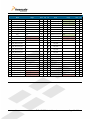
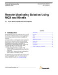
TWR-LCD-RGB User’s Manual Rev. 1.0 Freescale Semiconductor Inc. Contents 1 Overview ......................................................................................................................................................3 2 Reference Documents ..............................................................................................................................4 3 Hardware Features ...................................................................................................................................4 3.1 Tower System connection............................................................................................................................................... 4 3.2 Power Supply ....................................................................................................................................................................... 5 3.3 LCD Display / Driver ......................................................................................................................................................... 5 3.3.1 Timing parameters ............................................................................................................................................................................ 5 3.3.2 Communication Mode ...................................................................................................................................................................... 5 3.3.3 Resistive Touch Overlay .................................................................................................................................................................. 6 3.4 4-way Navigation Pad ....................................................................................................................................................... 7 4 Software Features .....................................................................................................................................7 4.1 Swell Software - http://swellsoftware.com ............................................................................................................ 7 4.2 eGUI Software - http://freescale.com/eGUI ........................................................................................................... 8 4.3 Loading Example Pre-Compiled Applications ........................................................................................................ 9 4.3.1 Setup the Tower System .................................................................................................................................................................. 9 4.3.2 Create a New Project for Flashing the TWR-K70F120M ................................................................................................... 9 5 Elevator Connections ............................................................................................................................ 10 6 Jumper Table ........................................................................................................................................... 13 6.1 Mechanical Form Factor ............................................................................................................................................... 13 TWR-LCD-RGB User’s Manual Page 2 of 13 1 Overview The Tower LCD RGB Module (TWR-LCD-RGB) adds a side mounting TFT WQVGA Display to the Freescale Tower System. It can be used with Tower Processor Modules featuring an RGB interfacing LCD Controller. The TWR-LCD-RGB features a 4.3” WQVGA TFT LCD Display with touch sensitive overlay. The LCD interfaces to the Tower System through a 24-bit RGB interface. The 4-wire resistive touch overlay can interface directly with a compatible Tower Processor Module using GPIO enabled ADC lines, or can offload the resistive touch sensing to the on-board Xtrinsic Touch Sensing Platform (CRTouch). 4.3" WQVGA (480x272) 24-bit TFT LCD w/ Resistive Touch Overlay Analog SPI Resistive Touch Analog (4x) Jumpers Analog TWR-ELEV (Secondary Expansion Port) 24-bit RGB, I2C, TSS, Analog 24-bit RGB HSYNC, VSYNC, CLK I2C CRTOUCH ReadyPlay Solution Capacitive Touch Pads Figure 1 - TWR-LCD-RGB Block Diagram TWR-LCD-RGB User’s Manual Page 3 of 13 Figure 2 - Tower System with TWR-LCD-RGB 2 Reference Material The documents listed below should be referenced for more information on the Freescale Tower system and the TWR-LCD-RGB. Refer to http://www.freescale.com/tower for the latest revision of all Tower documentation. TWR-LCD-RGB Schematics TWR-LCD-RGB Quick Start Guide Example Binary Application featuring Swell Software For additional software applications supporting the TWR-LCD-RGB refer to: http://freescale.com/eGUI http://freescale.com/peg http://swellsoftware.com 3 Hardware Features This section provides more details about the hardware specific features and functionality of the TWRLCD-RGB. 3.1 Tower System connection The TWR-LCD-RGB is designed to interface with the secondary side of the Freescale Tower System. The TWR-LCD-RGB comes pre-attached to an additional TWR-SELE (Secondary Elevator). The LCD module can be detached from the included TWR-SELE, but it is recommended that the modules remain attached to avoid any damage to the LCD glass when attempting to reconnect the modules. For Tower System assemblies that require use of the TWR-LCD-RGB, use the included pre-assembled TWR-LCD-RGB + TWR-SELE. TWR-LCD-RGB User’s Manual Page 4 of 13 3.2 Power Supply The TWR-LCD-RGB is designed to be powered via the Tower System and does not require a direct power source. The Freescale Tower System is capable of being powered directly over USB using the TWR-ELEV, the Processor Module, or specific peripheral modules. Depending on the number of modules in the Tower System and the amount of power required for each module it may be required to use a power source that can supply more than 500mA. Up to 2A may be required depending on the Tower System configuration. This can be accomplished by either a USB wall adapter or a 5V power supply, attached to the screw terminal of the TWR-ELEV. 3.3 LCD Display / Driver The TWR-LCD features an NEC color LCD module (NL4827HC19-05B), which his composed of an amorphous silicon thin film transistor liquid crystal display (a-Si TFT LCD) panel structure with driver LSIs for driving the TFT array, touch panel, and backlight. The display panel a 4.3” a-Si TFT active matrix with 16,777,216 colors, 480(H) x 272 (V) pixels, 24-bit RGB (8-bit per signal). 3.3.1 Timing parameters The following “typical” timing parameters are taken from the NL4827HC19-05B specification, for complete details refer to NEC for the latest data. Table 1 - NEC TFT Timing Parameters Parameter Clock Frequency HSYNC Cycle HSYNC Display Period HSYNC Front porch HSYNC Pulse width HSYNC Back porch VSYNC Cycle VSYNC Display Period VSYNC Front porch VSYNC Pulse width VSYNC Back porch Typical Value 10.87 20.7 480 2 41 2 75 272 1 2 1 Unit MHz kHz CLK CLK CLK CLK Hz CLK H H H 3.3.2 Communication Mode The TWR-LCD-RGB is accessible through the 24-bit RGB interface defined on the Secondary Tower Elevator Pin out. The integrated 4-wire resistive touch panel is accessible via the CRTouch using the I2C interface or optionally through the ADC signals. TWR-LCD-RGB User’s Manual Page 5 of 13 The signal specification required to drive the display is as follows: Table 2 – TWR-LCD-RGB TFT Signals TWR-SELE Description LCD_D[23:16] 8-bit Red data signal: LCD_D[23:16] -> R[7:0] LCD_D[15:8] 8-bit Green data signal: LCD_D[15:8] -> G[7:0] LCD_D[7:0] 8-bit Blue data signal: LCD_D[7:0] -> B[7:0] LCD_HSYNC Horizontal Sync Signal LCD_VSYNC Vertical Sync Signal LCD_CLK Clock LCD_DE Data Enable GPIO22 PWM15 Backlight Enable Signal ON/OFF signal, requires jumper J9 shunted on pins 2-3 Backlight Dimming Control signal, requires jumper J9 shunted on pins 1-2 Either GPIO22 or PWM15 must be appropriately driven. 3.3.3 Resistive Touch Overlay The TWR-LCD-RGB display features an integrated analog resistive touch panel. The panel can be access by either the on-board CRTouch Xtrinsic Touch Sensing Solution or a compatible Tower MCU module. The CRTouch is the preferred interface, allowing the most compatibility within the Freescale Tower System. The CRTouch features gesture detection such as slide, two-point zoom, and two-point rotate. The signal specification available to interface the 4-wire resistive touch overlay using the on-board CRTouch Xtrinsic Touch Sensing Solution is as follows: Table 3 – TWR-LCD-RGB 4-Wire Resistive Overlay Digital Signals TWR-SELE Description SDA2 I2C SDA signal from the CRTouch SCL2 I2C SCL signal from the CRTouch IRQ_I IRQ_M Optional Touch Pending Interrupt from CRTouch, Requires jumper J10 shunted on pins 1-2 Optional Touch Pending Interrupt from CRTouch, Requires jumper J10 shunted on pins 2-3 TWR-LCD-RGB User’s Manual Page 6 of 13 The signal specification available to interface the 4-wire resistive touch overlay directly from the MCU using GPIO capable ADC signals is as follows: Table 4 – TWR-LCD-RGB 4-Wire Resistive Overlay Analog Signals TWR-SELE AN11 AN10 AN9 AN8 Description X-axis right analog signal (XR) direct access to MCU ADC, requires jumper J8 shunted on pins 2-3 Y-axis down analog signal (YD) direct access to MCU ADC, requires jumper J5 shunted on pins 2-3 X-axis left analog signal (XL) direct access to MCU ADC, requires jumper J3 shunted on pins 2-3 Y-axis up analog signal (YU) direct access to MCU ADC, requires jumper J2 shunted on pins 2-3 3.4 4-way Navigation Pad The TWR-LCD-RGB features a 4-way navigation pad implemented using capacitive electrodes. The touch enables electrodes are accessible only through the CRTouch Xtrinsic Touch Sensing Solution. Refer to the CRTouch datasheet for details in reading the capacitive electrode states. 4 Software Features This section provides more details about the software specific features and enablement of the TWRLCD-RGB. 4.1 Swell Software - http://swellsoftware.com Swell Software provides Graphical User Interface (GUI) Solutions for Embedded Devices. Swell's PEG Pro, PEG+ and C/PEG product offering includes a Graphical User Interface (GUI) library for embedded development that works tightly with real-time operating systems. The development tool allows developers to layout user interface screens and controls using the PEG library and external resources to generate C/C++ code. The PEG WindowBuilder automatically generates C++ source code that is ready to be compiled and linked into any application, further accelerating the deployment of the final product. The TWR-LCD-RGB is supported in PEG Pro and PEG+ versions of the Swell Software GUI development suite. Official support is included PEG v2.3.13 and later. Screen drivers featuring the TWR-LCD-RGB are included for the following Tower Controller Modules: TWR-K70F120M TWR-PXD10 TWR-PXD20 TWR-VF65GS10 TWR-LCD-RGB User’s Manual Page 7 of 13 Selection of the TWR-LCD-RGB specific pre-defined Screen Driver is done using the “Screen Driver Configuration” panel within the Swell Window Builder application. The use of the CRTouch is specified using the appropriate pre-defined Touch Screen driver from the “Input/Output Configuration” panel within the Swell Window Builder application. Figure 3 - Window Builder Configuration Example projects are included with the installation of PEG Pro and PEG+. Additionally example precompiled applications are available for download at from the TWR-LCD-RGB webpage located on http://freescale.com/tower 4.2 eGUI Software - http://freescale.com/eGUI The complimentary Freescale embedded graphical user interface (eGUI) allows single chip microcontroller (MCU) systems to implement a graphical user interface and drive the latest generation of color graphics LCD panels with integrated display RAM and simple serial peripheral interface (SPI) or parallel bus interface. The TWR-LCD-RGB is officially supported in eGUI 3.0 and later releases. Selection of a low-level driver that utilizes the TWR-LCD-RGB is done through the d4d_user_cfg.h header file included with the installation of eGUI. As an reference example, below are the defines required to support the TWR-K70F120M with the TWR-LCD-RGB #define D4D_LLD_LCD d4dlcd_frame_buffer #define D4D_LLD_LCD_HW d4dlcdhw_k70_lcdc #define D4D_LLD_TCH d4dtch_cr_touch TWR-LCD-RGB User’s Manual Page 8 of 13 4.3 Loading Example Pre-Compiled Applications Several example applications are posted on the TWR-LCD-RGB webpage. The section below provides details regarding loading these applications on to the Tower System. These specific instructions detail flashing an example application on the TWR-K70F120M with the TWR-LCD-RGB. 4.3.1 Setup the Tower System Install the Tower System with the following Tower System modules: TWR-ELEV (Primary Elevator) Preassembled TWR-LCD-RGB + TWR-SELE (Secondary Elevator) TWR-K70F120M TWR-SER Attach the miniUSB connector between the TWR-K70F120M and the host PC. This will enable programming the TWR-K70F120M over the Open Source JTAG interface. Be aware that the example projects include a large amount of graphical assets that are compiled directly into the application. This results in a fairly large flash file. Using the Open Source JTAG interface can result in approximately a 5 minute flash process. 4.3.2 Create a New Project for Flashing the TWR-K70F120M Using CodeWarrior for MCU version 10.x 1. Open CodeWarrior for MCU v10.x 2. If required specify the desired workspace 3. Create a new project: File -> New -> Bareboard Project 4. Project a Project name, select Next 5. Select the following device: Kinetis -> K70 Family -> K70 (120 MHz) Family -> MK70FN1M0, select Finish 6. Right-click the newly created project and select Run -> Run Configuration 7. From the CodeWarrior Download section, select the <project_name>_MK70FN1M0_INTERNAL_FLASH_PnE U-Multilink option 8. From the C/C++ application section, select the Browse option associates with the Application field 9. Navigate to the location of the downloaded .out file and select Open 10. Select Run TWR-LCD-RGB User’s Manual Page 9 of 13 Using IAR Embedded Workbench 1. Open IAR Embedded Workbench for ARM 6.40 2. Create a new workspace: File -> New -> Workspace 3. Create a new project within blank workspace: Project -> Create New Workspace 4. Tool chain: ARM, Project Template: Externally built executable 5. Save the resulting project (.ewp) to a desired location 6. Right-click the project and select Options o General Options: Under Processor variant select Device and choose Freescale -> K70 -> Freescale MK70FN1M0xxx12 o Debugger: Under the Setup tab, Select the PE Micro Driver o Debugger: Under the Download tab, check the Use flash loader(s) option. 7. Add the .out file to the project: Project -> Add Files, navigate to the location of the .out file and select Open (make sure the File Filter is set to All Files (*.*) 8. Save the resulting workspace (.eww) to a desired location using File -> Save Workspace As 9. Flash the project using Project -> Download and Debug 10. Run the resulting application using Debug -> Go 5 Elevator Connections The TWR-LCD features two 80-pin connectors that interface to the Side Expansion Ports on the Secondary Elevator board in a Tower System. The Secondary Elevator Side Expansion Port connectors, comprised of sides C and D, are utilized by the TWR-LCD-RGB. The table below provides the pinout for the Secondary Elevator Connector. An “X” in the “Used” column indicated that there is a connection from the TWR-LCD-RGB to that pin on the Elevator connector. An “X” in the “Jmp” column indicates that a jumper is available that can configure or isolate the connection from the Elevator connector. Table 5 - TWR-LCD-RGB Secondary Elevator Expansion Pinout TWR-LCD-RGB Secondary Connector Pin Name D1 5V Pin Name 5.0V Power Usage Used X Jmp C1 5V D2 D3 GND Ground X C2 3.3V 3.3V Power X C3 D4 ELE_PS_SENSE D5 GND Ground D6 GND SPI2_CLK Ground D7 D8 SPI2_CS1_b D9 SPI2_CS0_b C9 GPIO25 D10 SPI2_MOSI C10 ULPI_STOP D11 SPI2_MISO C11 C11 D12 ETH_COL C12 GPIO26 D13 ETH_RXER C13 ETH_MDC Usage Used 5.0V Power X GND Ground X 3.3V 3.3V Power X C4 3.3V 3.3V Power X X C5 GND Ground X X C6 C7 GND SCL2 Ground CRTOUCH SCL X X C8 SDA2 CRTOUCH SDA X RESET_IN_B X Elevator Power Sense TWR-LCD-RGB User’s Manual Page 10 of 13 Jmp X TWR-LCD-RGB Secondary Connector Pin D14 Name ETH_TXCLK Usage Used Jmp Pin C14 Name ETH_MDIO D15 ETH_TXEN C15 ETH_RXCLK D16 GPIO18 C16 ETH_RXDV D17 GPIO19 / SDHC_D4 C17 GPIO27 / SDHC_D6 D18 GPIO20 / SDHC_D5 C18 GPIO28 / SDHC_D7 D19 ETH_TXD1 C19 ETH_RXD1 D20 ETH_TXD0 C20 D21 ULPI_NEXT / USB1_DM C21 D22 ULPI_DIR / USB1_DP C22 D23 UPLI_DATA5 / USB2_DM C23 D24 ULPI_DATA6 / USB2_DP C24 D25 ULPI_DATA7 ETH_RXD0 ULPI_DATA0 / USB3_DM ULPI_DATA1 / USB3_DP ULPI_DATA2 / USB4_DM ULPI_DATA3 / USB4_DP ULPI_DATA4 D26 D27 GND LCD_HSYNC / LCD_P24 Ground RGB_Hsync X X D28 LCD_VSYNC / LCD_P25 RGB_Vsync X D29 D30 D31 D32 GND LCD_CLK / LCD_P26 D33 C25 Used Jmp C27 GND AN11 Ground Resistive Touch XR X X X C28 AN10 Resistive Touch YD X X AN13 C29 AN9 Resistive Touch XL X X AN12 C30 AN8 Resistive Touch YU X X C31 GND GPIO29 Ground X C32 TMR11 C33 TMR9 D34 TMR10 C34 TMR8 D35 GPIO21 C35 GPIO30 D36 C36 X C37 3.3V PWM11 3.3V Power D37 3.3V PWM15 D38 PWM14 C38 PWM10 D39 PWM13 C39 PWM9 D40 PWM12 C40 PWM8 D41 CANRX1 C41 RXD2 / TSI0 D42 CANTX1 C42 TXD2 / TSI1 D43 GPIO22 / Backlight LCD_ENABLE X C43 RTS2 / TSI2 D44 LCD_OE / LCD_P27 RGB_DE X C44 CTS2 / TSI3 D45 LCD_D0 / LCD_P0 BLUE Data Signal B0 (LSB) X C45 RXD3 / TSI4 D46 LCD_D1 / LCD_P1 BLUE Data Signal B1 X C46 TXD3 / TSI5 D47 LCD_D2 / LCD_P2 BLUE Data Signal B2 X C47 RTS3 / TSI6 D48 LCD_D3 / LCD_P3 BLUE Data Signal B3 X C48 CTS3 / TSI7 D49 Ground X C49 GND D50 GND GPIO23 C50 LCD_D4 / LCD_P4 Ground BLUE Data Signal B4 X X D51 GPIO24 C51 LCD_D5 / LCD_P5 BLUE Data Signal B5 X D52 LCD_D12 / LCD_P12 GREEN Data Signal G4 X C52 LCD_D6 / LCD_P6 X D53 LCD_D13 / LCD_P13 GREEN Data Signal G5 X C53 LCD_D7 / LCD_P7 D54 LCD_D14 / LCD_P14 GREEN Data Signal G6 X C54 BLUE Data Signal B6 BLUE Data Signal B7 (MSB) GREEN Data Signal G0 (LSB) Ground RGB_CLK C26 Usage X X 3.3V Power LED_PWM X X X X LCD_D8 / LCD_P8 TWR-LCD-RGB User’s Manual X X Page 11 of 13 TWR-LCD-RGB Secondary Connector Pin D55 Name IRQ_P / SPI2_CS2_b Usage C55 Name LCD_D9 / LCD_P9 D56 IRQ_O / SPI2_CS3_b C56 LCD_D10 / LCD_P10 GREEN Data Signal G2 X D57 IRQ_N C57 LCD_D11 / LCD_P11 GREEN Data Signal G3 X D58 IRQ_M C58 TMR16 D59 IRQ_L C59 TMR15 D60 IRQ_K C60 TMR14 D61 IRQ_J C61 TMR13 IRQ_B Used X Jmp X Pin Usage GREEN Data Signal G1 Used X D63 LCD_D18 / LCD_P18 RED Data Signal R2 X C63 LCD_D16 / LCD_P16 GREEN Data Signal G7 (MSB) RED Data Signal R0 (LSB) D64 LCD_D19 / LCD_P19 RED Data Signal R3 X C64 LCD_D17 / LCD_P17 RED Data Signal R1 X D65 GND Ground X C65 Ground X D66 EBI_AD20 / LCD_P42 C66 D67 EBI_AD21 / LCD_P43 C67 D68 EBI_AD22 / LCD_P44 C68 D69 C69 D70 EBI_AD23 / LCD_P45 EBI_AD24 / LCD_P46 GND EBI_BE_32_24_b / LCD_P28 EBI_BE_23_16_b / LCD_P29 EBI_BE_15_8_b / LCD_P30 EBI_BE_7_0_b / LCD_P31 C70 EBI_TSIZE0 / LCD_P32 D71 EBI_AD25 / LCD_P47 C71 EBI_TSIZE1 / LCD_P33 D72 EBI_AD26 / LCD_P48 C72 EBI_TS_b / LCD_P34 D73 EBI_AD27 / LCD_P49 C73 EBI_TBST_b / LCD_P35 D74 EBI_AD28 / LCD_P50 C74 EBI_TA_b / LCD_P36 D75 EBI_AD29 / LCD_P51 C75 EBI_CS4_b / LCD_P37 D76 EBI_AD30 / LCD_P52 C76 EBI_CS3_b / LCD_P38 D77 EBI_AD31 / LCD_P53 C77 EBI_CS2_b / LCD_P39 D78 LCD_D20 / LCD_P20 RED Data Signal R4 X C78 EBI_CS1_b / LCD_P40 D79 LCD_D21 / LCD_P21 RED Data Signal R5 X C79 GPIO31 / LCD_P41 D80 LCD_D22 / LCD_P22 RED Data Signal R6 X C80 LCD_D23 / LCD_P23 RED Data Signal R7 (MSB) X D62 IRQ_I IRQ_A X X C62 LCD_D15 / LCD_P15 TWR-LCD-RGB User’s Manual X X Page 12 of 13 Jmp 6 Jumper Table The following configuration switches provided for isolation, configuration, and feature selection. Refer to the following table for details. The default installed dip switch settings are shown in bold. Table 6 - TWR-LCD-RGB Configuration Table Jumper Option J2 Y+ Selection J3 X- Selection J5 Y- Selection J8 X+ Selection J9 LED DIM Control J10 IRQ Selection Setting 1-2 2-3 1-2 2-3 1-2 2-3 1-2 2-3 1-2 2-3 1-2 2-3 Description Use the onboard CRTouch Routes the Y+ signal to the AN8 (ELEV C30) Use the onboard CRTouch Routes the X- signal to the AN9 (ELEV C29) Use the onboard CRTouch Routes the Y- signal to the AN10 (ELEV C28) Use the onboard CRTouch Routes the X+ signal to the AN11 (ELEV C27) Uses PWM15 (ELEV D37) to control the LED brightness Uses GPIO22 (ELEV D43) to control the LED on/off state CRTouch IRQ is connected to IRQ_I (ELEV D62) CRTouch IRQ is connected to IRQ_K (ELEV D64) 6.1 Mechanical Form Factor The TWR-LCD-RGB is designed for the Freescale Tower System as a side mounting peripheral and complies with the electrical and mechanical specification as described in Freescale Tower Electromechanical Specification. The TWR-LCD-RGB is intended for use on the secondary side only and come pre-assembled to the TWR-SELE. Freescale™ and the Freescale logo are trademarks of Freescale Semiconductor, Inc. All other product or service names are the property of their respective owners. © Freescale Semiconductor, Inc. 2009. All rights reserved. TWR-LCD-RGB User’s Manual Page 13 of 13