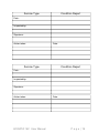
1
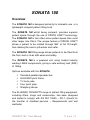
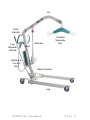
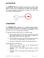
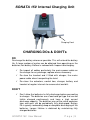
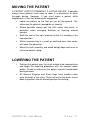
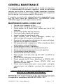
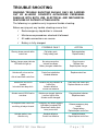
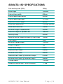
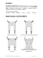
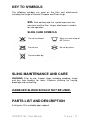
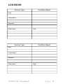
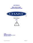
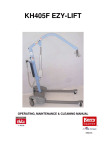
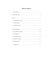
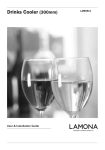
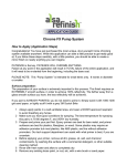
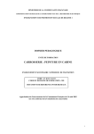
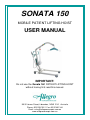
SONATA 150
MOBILE PATIENT LIFTING HOIST
USER MANUAL
IMPORTANT:
Do not use the Sonata 150 PATIENT LIFTING HOIST
without having first read this manual.
30-32 James Street, Lidcombe, NSW 2141 Australia
Phone: 02 9749 7812 Fax: 02 9749 2144
Email: [email protected]
www.allegroconcepts.com.au
CONTENTS
SONATA 150 Overview
3
Important safety considerations
4
SONATA 150 Assembly instructions
6
Hoist operation and charging
7
Lifting procedures
10
Maintenance
12
Trouble shooting 13
Specifications
14
Warranty 15
SONATA 150 User Manual
Slings
16
Key to symbols
17
Parts list
17
Log Book
18
Page |2
SONATA 150
Overview
The SONATA 150 is designed primarily for domestic use or a
lightweight compact patient lifting hoist
The SONATA 150 whilst being compact, provides superior
patient space through the use of SPACE LINK™ technology.
The SONATA 150 in fact offers more patient space than most
other larger size lifters. The unique feature of SPACE LINK™
allows a patient to be rotated through 360° at full lift height,
thus making the carer’s job easier and safer.
The SONATA 150 lifting range allows patients to be lifted from
the floor, bed or chair with ease and safety.
The SONATA 150 is a powered unit using trusted industry
leading LINAK components, giving a safe working load (SWL)
of 150kg
Options available with the SONATA
Standard padded spreader bar
ALLEGRO pivot frame
Tri hook yoke
Four point yoke
Weighing device
The ALLEGRO CONCEPTS range of patient lifting equipment,
including lifters, slings and accessories, has been designed
and tested to comply with AS ISO 10535 – 2011, (Hoists for
the transfer of disabled persons – Requirements and test
methods)
SONATA 150 User Manual
Page |3
IMPORTANT SAFETY CONSIDERATIONS
INTENDED USE OF THE PRODUCT
The SONATA 150 compact mobile patient lifting hoist has been
designed to lift and transfer a less able person with the assistance of
a carer.
The SONATA 150 should be used with one of the ALLEGRO range
of patient slings, as assessed by a competent trained person.
NB. Not all slings and accessories are compatible with this hoist. If
you are unsure please contact ALLEGRO CONCEPTS.
The correct and appropriate use of the SONATA 150 hoist will
reduce the risks associated with manual patient handling. The lifting /
transferring task should be assessed & planned by a trained user.
SAFETY CONSIDERATIONS
Ensure that all users read this guide before operating the
hoist.
Do not operate the hoist without training in the safe
operation of hoists & slings. IF IN DOUBT DO NOT USE.
Only use slings which have been assessed as suitable by a
competent trained professional.
Read the relevant sling users guide which is provided with
each sling, before use.
Do not use the hoist if there is any doubt about wear or
damage to the unit. In particular the spreader bar or the
ALLEGRO Pivot Frame.
Do not use the hoist if there is any fraying or stitch damage
to the sling or if the sling is damaged in any other way.
DO NOT EXCEED THE SAFE WORKING LOAD OF THE
SONATA 150 HOIST – 150kg
Ensure when the hoist is in use that the surrounding area is
clear and the person being lifted is clear of all obstructing
objects.
SONATA 150 User Manual
Page |4
Jib
Push
Handle
Leg
Adjuster
Handle
Padded
Spreader
Bar
Actuator
Mast
Battery &
Control
Box
Base Chassis
Leg
SONATA 150 User Manual
Page |5
ASSEMBLY INSTRUCTIONS
SONATA 150
The ALLEGRO range of patient lifting and transfer hoists are fully
assembled, load tested and certified at the factory before being partially
dismantled for packing and shipping.
Use the instructions below as a guide to assemble your SONATA 150
hoist.
1.
Remove lifter components from protective packing and lay out
on a smooth surface to prevent damage to powder coating on
lifter sub assemblies.
2.
Lift the mast assembly and slide into mast holder receiving
socket on base chassis. Ensure the mast assembly is
completely engaged in the mast socket. Tighten the locking
clamp hex bolt to prevent movement between mast and base
chassis.
3.
Attach lift actuator to jib, by aligning actuator clevis with actuator
mount bracket. Insert bolt and tighten nylock nut.
4.
Attach push handle assembly with hex bolts supplied with
handle assembly.
5.
Insert the leg adjusting handle into the socket of the leg
adjustable pivot mounted on the base chassis. Ensure handle
key is aligned with cut-outs on the pivot
6.
Check the operation of the leg adjustment mechanism to ensure
the adjuster handle engages the three detent positions with
ease of movement
7.
Attach battery by clipping battery pack on top of control box.
8.
Plug the lift actuator cable into port 1 positioned on the
underside of the control box, ensuring it is driven firmly home in
the socket.
9.
Plug the handset lead into the large socket on underside of
control box. (See next diagram) ensure alignment of tongue on
handset plug with groove in control box handset connection
port. When aligned press home firmly. A smear of Vaseline on
the o ring may assist if plug is tight.
10. Check operation of lifter via handset, ensuring that the RED
EMERGENCY STOP BUTTON ON THE CONTROL BOX IS
RELEASED. Turn the knob quarter turn clockwise to release.
SONATA 150 User Manual
Page |6
HOIST OPERATION AND CHARGING
HANDSET
The handset activates the lift actuator by the use of two low
pressure buttons, protected by a strong plastic cover. These
are symbolised by arrows (diagram). The arrows indicate the
direction of travel to raise or lower the hoist jib. When either
button is released the jib will remain in position.
The SONATA 150 hoist incorporates an actuator driven leg
opening adjustment. Two buttons will be seen on the
handset with arrows and symbolised legs indicating the
direction of travel. This function allows an unrestricted range
of leg adjustment.
The handset is also fitted with a battery indicator light. This
will flash when the batteries reach a maximum discharge of
18 volts. NB the light will only flash when the hoist is under
load.
The connection for the handset is located on the underside
of the control box.
Handset Port
Lift Actuator –
Port 1
SONATA 150 User Manual
Page |7
ACTUATOR
The SONATA 150 mobile patient lifting hoist uses a LINAK single
speed actuator with an emergency controlled lowering release
handle. (Twist red collar located at top of actuator shaft clockwise).
This allows the patient to be lowered in the event of a fault in the
hoist or deep discharged batteries.
CHARGING
The SONATA 150 is supplied with a integrated battery charger.
This is powered by plugging the 3 pin plug into a standard 240V ac
outlet when lifter is not in use. The charger may be plugged in at any
time whilst not in use, to top up battery charging.
To recharge the battery pack, perform the following steps
1) Release battery pack from control box by pulling the handle
on the pack towards you. Use both hands to support the
battery pack when removing nor replacing it.
2) Clip the battery pack from the control box onto the charging
unit, ensuring it is seated properly on the charger base
3) Charger will automatically activate the charging sequence
CHARGING INDICATOR DISPLAY
GREEN mains power on light will be illuminated when
connected to 240 v power supply.
ORANGE LIGHT illuminated indicates battery currently
charging.
ORANGE LIGHT will extinguish when battery pack is fully
charged.
SONATA 150 User Manual
Page |8
SONATA 150 Internal Charging Unit
Charging Cord
CHARGING DOs & DON’Ts
DO
Do charge the battery whenever possible. This will extend the battery
life. A large number of cycles can be obtained from operating on the
batteries, but battery lifetime is reduced with frequent discharging.
Do inspect all cables particularly the mains power cable on
the charger for any damage; replace where necessary.
Do stow the handset and if fitted with charger, the mains
power cable when transporting the hoist.
Do clean the actuators, control box, charger, battery and
handset at regular intervals to remove dust and dirt.
DON’T
Don’t allow the batteries to fully discharge before connecting
to charger. The batteries are a lead acid gel type that can be
trickle charged continuously and have a high current
discharge capacity. The batteries are not the nickel cadmium
type and must not be periodically fully discharged. Battery
life is greatly reduced by deep or complete discharging of the
batteries. Longer lifetime is obtained by maintaining fully
charged batteries.
SONATA 150 User Manual
Page |9
LIFTING PROCEDURES
Carer should be fully conversant and trained in the use of
lifter and sling. This will decrease patient apprehension and
increase their co-operation and overall safety of the lifting
process.
Where possible always pull the lifter for maximum safety and
comfort.
Move the hoist slowly to avoid patient swing whilst standing.
The hoist should not be used on uneven surfaces or on an
incline greater than 5 deg.
Never leave a patient in a sling unattended.
Ensure brakes of the chair, bed, trolley that the patient is
being lifted from are locked.
The braking castors on the lifter should be off. This allows
the lifter to create its own centre of gravity (C.G,) over the
weight of the patient. N,B. This action may result in the lifter
moving slightly during the initial phase of the lift.
GENERAL LIFTING PROCEDURE
The information supplied below is not intended to be construed as a
training manual but as a general guide to lifting procedure only.
Fit sling to patient (REFER TO SLING INSTRUCTION FOR USE).
Manoeuvre the hoist around the patient, adjusting the legs to
fit around chair, wheel chair etc. If lifting from a bed ensure
under bed clearance is sufficient to manoeuvre the lifter legs.
Lower the spreader bar sufficiently to allow fitting of sling
attachment loops onto the spreader bar hooks. Ensure
spreader bar does not contact with patients face or body.
If using the ALLEGRO Pivot Frame, lower the Pivot Frame
sufficiently to allow attachment of the keyhole buckles onto
the Pivot Frame studs.
Use the handset to raise the hoist boom enough to take up
the patients weight. At this point stop the lift, check all sling
attachments are secure and that the sling is positioned
correctly. Check patient comfort. Lower and realign sling if
necessary.
Continue to lift until patient is clear of chair, bed etc.
ensuring that during the course of the lift the patient is clear
of any obstructions.
SONATA 150 User Manual
P a g e | 10
MOVING THE PATIENT
A PATIENT HOIST IS PRIMARILY A LIFTING DEVICE. If possible
always move patients from room to room in a wheelchair or other
transport device. However, If you must move a patient while
supported in a lifter the following are suggested:
Lower the patient so the feet are just off the ground. This
enhances the patients’ perception of security.
Where possible always pull the lifter rather than push, in
particular when changing direction or steering around
corners.
Walk the rear of the hoist around so that it is heading in the
new direction.
Whilst manoeuvring in a small or confined area, two carers
will make the job easier.
Move the hoist smoothly and avoid abrupt stops and turns to
minimise patient swing.
LOWERING THE PATIENT
Position the patient over the chair or bed to be lowered onto
and begin the lowering procedure with the handset down
button. Check to make sure the patient remains comfortable
during descent.
.
All General Purpose and Pivot slings have handles sewn
onto the back of the sling. These will assist the carer to pull
back the patient into the correct position for seating.
SONATA 150 User Manual
P a g e | 11
GENERAL MAINTENANCE
To prolong the working life of the lifter and for trouble free operation
it is recommended that periodic inspections should be performed
routinely and as often as necessary. Periodic inspections should be
performed by a person who is suitably qualified and well acquainted
with the design, use and care of patient lifting hoists.
If inspection reveals that the safety of the hoist is jeopardised in any
way the hoist should be IMMEDIATELY WITHDRAWN FROM
SERVICE, tagged as such and the owner notified.
MAINTENANCE GUIDE & CHECK LIST
General visual inspection of lifter.
Check castors are tightly attached to legs.
Check castors run & swivel freely, remove any hair & fluff
from axle.
Check castor brakes operate efficiently.
Over haul castors & pack with grease.
Inspect surfaces for scratches & chips
Clean surfacers with a neutral detergent; remove any
adhesive tape with orange or eucalyptus oil.
Examine all moving parts and fasteners for wear and fatigue,
lubricate and /or adjust as required.
NB leg pivot bushes incorporate a Teflon coated pivot bush
which requires minimal lubrication.
Check tightness of bolt in leg bushes.
Check linkages are secure in leg adjuster ball joints.
Check all electrical components for correct operation.
Check battery charger operation.
Remove dirt & dust from actuator.
Wipe actuator shaft with oiled rag (DO NOT use WD40 or
equivalent.)
Check SPACE LINK pivot link and regrease.
Check spreader bar/tilt frame attachment to SPACE LINK.
Remove bolt & regrease. Ensure SPACE LINK and
attachments move freely.
Check mast to boom pivot point, remove bolts and lightly
regrease bush and retighten, ensuring free movement at
pivot.
A MAJOR SERVICE SHOULD BE CARRIED OUT EVERY 12
MONTHS AS A MINIMUM REQUIREMENT.
IMPORTANT: An annual load test to the safe working load (swl)
is required for compliance with AS ISO 10535 – 2011
SONATA 150 User Manual
P a g e | 12
TROUBLE SHOOTING
WARNING TROUBLE SHOOTING SHOULD ONLY BE CARRIED
OUT BY ALLEGRO CONCEPTS AUTHORISED PERSONNEL
FAMILIAR WITH BOTH USE, ELECTRICAL AND MECHANICAL
FEATURES OF PATIENT LIFTING HOISTS.
The following is a guideline only to general trouble shooting.
Before carrying out any trouble shooting ensure that.
Red emergency stop button is released.
Maintenance procedures checked & followed.
All cable connections are secure.
Battery is fully charged.
POSSIBLE FAULT
ACTION
Warning buzzer sounds within
control box
Flat battery pack.
Faulty battery pack.
Recharge battery.
Replace battery.
Battery charger power indicator
LED does not light up.
No mains connection.
Internal fuse blown.
Battery chargers is defective.
Plug into mains.
Replace fuse.
Repair/replace charger.
Actuator will not run and no
relay
click is heard from control box.
Control box is defective.
Handset defective
Replace control box.
Actuator will not run via
handset
but control box relays click.
Actuator plug not pushed in to
control box,
Actuator defective.
Control box defective.
Push firmly into correct port.
Replace actuator or control.
Actuator cannot lift full load or
runs slow.
Batteries not charged / defective.
Charge/replace batteries.
Replace actuator.
No response from control box,
no clicking of relays is heard.
Emergency stop button engaged.
Hoist battery completely flat.
Blown fuse in battery pack.
Actuator works in one
direction only
Load too high for lifter.
Actuator motor damaged.
Faulty control box.
Release emergency stop
button.
Charge battery.
Replace/repair control box.
Handset defective.
Control box defective.
Replace handset.
Repair/replace control box.
SONATA 150 User Manual
P a g e | 13
SONATA 150 SPECIFICATIONS
Safe working load (SWL)
150kg
Base length
1005mm
External base width
605mm
Internal base width closed
530mm
Internal base width open
1010mm
Maximum internal length
860mm
Base width adjustment
3 Position Manually
Under bed clearance
125mm
Minimum height of spreader bar
340mm
Maximum height of spreader bar
1685mm
Hoisting range
930mm
Height of centre suspension point @ max reach
134mm
Lifter weight
39kg
Minimum storage height
1235mm
Patient lift space
165
Under base height
50mm
Maximum hoist reach
875mm
Minimum hoist reach
445mm
Maximum hoist reach @ maximum height
610mm
Minimum hoist reach @ minimum height
435mm
Turning radius
1100mm
Weight of heaviest part (Base assembly)
17.5kg
SONATA 150 User Manual
P a g e | 14
WARRANTY
ALLEGRO CONCEPTS PTY LTD warrants its products to be free
from defects in materials and workmanship under normal use and
service and will within the period stated below, from the date of
purchase, repair or replace without cost to the original customer, any
part assembly or portion thereof which shall be returned to
ALLEGRO CONCEPTS PTY LTD and from OUR inspection shows
to be defective.
Patient lifter including electronics 2 years
Accessories on lifter 2 years
Patient slings 1 year
Weighing devices 1 year
Batteries 3 months
ALLEGRO CONCEPTS PTY LTD cannot be held responsible for
any personal injury, damage to the hoist or damage to property as a
result of the improper or unsafe use of the product.
No warranty claim shall apply where the product or any part thereof
has been modified, varied, altered or damaged either accidentally or
through improper or negligent use
No warranty claim shall apply where the hoist is repaired or serviced
by any persons not accredited by the authorised distributor.
Warranty does not extend to items or components which may require
replacement due to normal wear and tear ( e.g. castors, mouldings
and paint work ) for which ALLEGRO CONCEPTS PTY LTD nor its
distributors can be held responsible.
BATTERIES
Batteries carry a limited warranty from the original manufacturer
which is subject to a stringent wear and tear clause. Any battery
faults due to defect in original manufacture will normally become
apparent within the first two months of use.
Any gradual deterioration in performance after this period is normally
associated with fair wear and tear, misuse and accidental damage,
and as such is not covered by the manufacturers’ warranty.
SONATA 150 User Manual
P a g e | 15
SLINGS
ALLEGRO CONCEPTS PTY LTD manufactures a large range of
patient lifting slings in both mesh and fabric to suit the ALLEGRO
range of patient lifting hoists. A range of custom made to
specification slings are available on request.
SLING SIZES AVAILABLE
• X small, • Small, • Medium,
• Large,
• X large,
• XX large
MAIN SLING CATEGORIES
General Purpose Sling
General Purpose Sling with Head Support
Pivot Sling
Amputee Sling
SONATA 150 User Manual
P a g e | 16
KEY TO SYMBOLS
The following symbols are used on the lifter and attachments
including the range of General Purpose and Pivot slings.
SWL Safe working load: this symbol represents the
maximum load the lifter, sling or attachment is rated to
for safe operation.
SLING CARE SYMBOLS
Do not use bleach.
Wash at a max temp of
85º Celsius.
Do not iron.
Do not dry clean.
Do not tumble dry.
SLING MAINTENANCE AND CARE
WARNING: Prior to use, inspect slings including webbing, straps
and key hole buckles for wear. Examine stitching for fraying,
breakage and unravelling.
DAMAGED SLINGS SHOULD NOT BE USED.
PARTS LIST AND DESCRIPTION
A full parts lift is available upon request
SONATA 150 User Manual
P a g e | 17
LOG BOOK
Service Type
Condition Report
Date:
Inspected by:
Signature:
Action taken:
Date:
Service Type
Condition Report
Date:
Inspected by:
Signature:
Action taken:
SONATA 150 User Manual
Date:
P a g e | 18
Service Type
Condition Report
Date:
Inspected by:
Signature:
Action taken:
Date:
Service Type
Condition Report
Date:
Inspected by:
Signature:
Action taken:
SONATA 150 User Manual
Date:
P a g e | 19
Distributed By:
30-32 James Street, Lidcombe, NSW 2141 Australia
Phone: 02 9749 7812 Fax: 02 9749 2144
Email: [email protected]
www.allegroconcepts.com.au
SONATA 150 User Manual
P a g e | 20