1
Drehstrom-Synchronmotoren 8LS Anwenderhandbuch
ACOPOSmulti
User´s Manual
MAACP2-GER
Version 1.1
MAACPM-ENG
ACOPOSmulti
User's Manual
Version:
Model number:
0.31 (May 2007)
MAACPM-ENG
All information contained in this manual is current as of its creation/publication. We reserve the
right to change the contents of this manual without warning. The information contained herein is
believed to be accurate as of the date of publication; however, Bernecker + Rainer IndustrieElektronik Ges.m.b.H. makes no warranty, expressed or implied, with regard to the products or
the documentation contained within this book. In addition, Bernecker + Rainer IndustrieElektronik Ges.m.b.H. shall not be liable in the event of incidental or consequential damages in
connection with or resulting from the furnishing, performance, or use of these products. The
software names, hardware names, and trademarks used in this document are registered by the
respective companies.
ACOPOSmulti User's Manual V 0.31
1
2
ACOPOSmulti User's Manual V 0.31
Chapter 1: General information
Chapter 2: Technical data
Chapter 3: Mounting
Chapter 4: Dimensioning
Chapter 5: Wiring
Chapter 6: Getting Started
ACOPOSmulti User's Manual V 0.31
3
4
ACOPOSmulti User's Manual V 0.31
Chapter 7: Standards and certifications
Figure index
Table index
Index
Model number index
ACOPOSmulti User's Manual V 0.31
5
6
ACOPOSmulti User's Manual V 0.31
Table of contents
Table of contents
Chapter 1: General information ..................................................... 13
1. Manual history ....................................................................................................................
2. Safety guidelines ................................................................................................................
2.1 General information .......................................................................................................
2.2 Intended use ..................................................................................................................
2.3 Protection against electrostatic discharges ...................................................................
2.3.1 Packaging ...............................................................................................................
2.3.2 Guidelines for proper ESD handling .......................................................................
2.4 Transport and storage ...................................................................................................
2.5 Installation .....................................................................................................................
2.6 Operation .......................................................................................................................
2.6.1 Protection against touching electrical parts ............................................................
2.6.2 Protection from dangerous movements ..................................................................
2.7 Organization of safety notices .......................................................................................
13
16
16
16
17
17
17
18
18
19
19
20
20
Chapter 2: Technical data .............................................................. 21
1. Configuration of an ACOPOSmulti drive system ................................................................
2. Indications ...........................................................................................................................
2.1 8BVP power supply modules ........................................................................................
2.1.1 LED Status .............................................................................................................
2.2 8B0C auxiliary supply module .......................................................................................
2.2.1 LED Status .............................................................................................................
2.3 8BVI inverter modules ...................................................................................................
2.3.1 Single-axis modules ................................................................................................
2.3.2 Two-axis modules ...................................................................................................
2.4 LED Status ....................................................................................................................
2.4.1 Ethernet POWERLINK ............................................................................................
2.4.2 Status changes when booting the operating system loader ...................................
3. Line filter 8BVF ...................................................................................................................
3.1 Order data .....................................................................................................................
3.2 Technical data ...............................................................................................................
4. 8BVR regeneration chokes .................................................................................................
4.1 Order data .....................................................................................................................
4.2 Technical data ...............................................................................................................
5. 8B0M mounting plates ........................................................................................................
5.1 Order data .....................................................................................................................
5.2 Technical data ...............................................................................................................
6. 8BVP power supply modules ..............................................................................................
6.1 Order data .....................................................................................................................
6.2 Technical data ...............................................................................................................
7. 8B0C control supply unit - 400W ........................................................................................
7.1 Order data .....................................................................................................................
7.2 Technical data ...............................................................................................................
8. 8B0C control supply units - 800W ......................................................................................
8.1 Order data .....................................................................................................................
8.2 Technical data ...............................................................................................................
ACOPOSmulti User's Manual V 0.31
21
22
22
23
24
24
25
25
27
29
29
29
30
30
31
33
33
33
35
35
36
38
38
40
44
44
45
49
49
50
7
Table of contents
9. Inverter modules 8BVI 1kW ... 8kW (single-axis modules) .................................................
9.1 Order data .....................................................................................................................
9.2 Technical data ...............................................................................................................
10. Inverter modules 8BVI 1kW ... 4kW (two-axis modules) ...................................................
10.1 General information .....................................................................................................
10.2 Order data ...................................................................................................................
10.3 Technical data .............................................................................................................
11. 8BVI inverter modules, 32kW ...........................................................................................
11.1 Order data ...................................................................................................................
11.2 Technical data .............................................................................................................
12. 8BVI inverter modules, 64kW ...........................................................................................
12.1 Order data ...................................................................................................................
12.2 Technical data .............................................................................................................
13. EnDat 2.1 plug-in module 8BAC0120.000-1 .....................................................................
13.1 General description .....................................................................................................
13.2 Order data ...................................................................................................................
13.3 Technical data .............................................................................................................
13.3.1 Indications .............................................................................................................
13.3.2 Firmware ...............................................................................................................
14. HIPERFACE plug-in module 8BAC0121.000-1 ................................................................
14.1 General description .....................................................................................................
14.2 Order data ...................................................................................................................
14.3 Technical data .............................................................................................................
14.3.1 Indications .............................................................................................................
14.3.2 Firmware ...............................................................................................................
15. Resolver plug-in module 8BAC0122.000-1 ......................................................................
15.1 General description .....................................................................................................
15.2 Order data ...................................................................................................................
15.3 Technical data .............................................................................................................
15.3.1 Indications .............................................................................................................
15.3.2 Firmware ...............................................................................................................
16. SinCos plug-in module 8BAC0124.000-1 .........................................................................
16.1 General description .....................................................................................................
16.2 Order data ...................................................................................................................
16.3 Technical data .............................................................................................................
16.3.1 Indications .............................................................................................................
16.3.2 Firmware ...............................................................................................................
54
54
55
60
60
60
61
66
66
67
72
72
73
78
78
79
80
82
82
83
83
84
84
86
86
87
87
87
88
90
90
91
91
91
91
94
94
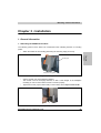
Chapter 3: Installation .................................................................... 95
1. General information ............................................................................................................
1.1 Mounting ACOPOSmulti modules .................................................................................
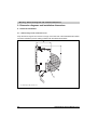
2. Dimension diagrams and installation dimensions ...............................................................
2.1 General information .......................................................................................................
2.1.1 Swivel range of the connector cover .......................................................................
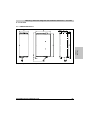
2.2 Line filter ........................................................................................................................
2.2.1 8BVF0440H000.001-1 ............................................................................................
8
95
95
96
96
96
97
97
ACOPOSmulti User's Manual V 0.31
Table of contents
2.2.2 8BVF0880H000.000-1 ............................................................................................ 98
2.3 Regeneration chokes .................................................................................................... 99
2.3.1 8BVR0440H000.100-1 ............................................................................................ 99
2.3.2 8BVR0880H000.100-1 .......................................................................................... 100
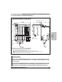
2.4 Wall mounting .............................................................................................................. 101
2.4.1 Mounting plate 8B0MnnnnHW00.000-1 ............................................................... 101
2.4.2 Inverter module 8BVI0055HWD0.000-1 ............................................................... 102
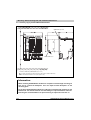
2.5 Cold plate mounting .................................................................................................... 103
2.5.1 Mounting plate 8B0MnnnnHC00.000-1 ................................................................ 103
2.5.2 Power supply module 8BVP0880HC00.000-1 ...................................................... 104
2.5.3 Auxiliary supply module 8B0C0160HC00.000-1 ................................................... 105
2.5.4 Auxiliary supply module 8B0C0160HC00.001-1 ................................................... 106
2.5.5 Inverter module 8BVI0055HCS0.000-1 ................................................................ 107
2.5.6 Inverter module 8BVI0055HCD0.000-1 ................................................................ 108
2.5.7 Inverter module 8BVI0880HC00.000-1 ................................................................. 109
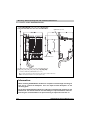
2.6 Feed-through mounting ............................................................................................... 110
2.6.1 Mounting plate 8B0MnnnnHF00.000-1 ................................................................ 110
2.6.2 Power supply module 8BVP0880HC00.000-1 ...................................................... 111
2.6.3 Auxiliary supply module 8B0C0160HC00.000-1 ................................................... 112
2.6.4 Inverter module 8BVI0055HCS0.000-1 ................................................................ 113
2.6.5 Inverter module 8BVI0055HCD0.000-1 ................................................................ 114
2.6.6 Inverter module 8BVI0880HC00.000-1 ................................................................. 115
Chapter 4: Dimensioning ............................................................. 117
1. Power mains connection ...................................................................................................
1.1 General information .....................................................................................................
1.1.1 System configuration ............................................................................................
1.1.2 Supply voltage range ............................................................................................
1.1.3 Protective Ground Connection (PE) ......................................................................
1.2 Dimensioning ...............................................................................................................
1.2.1 Design of the ACOPOSmulti power mains connections .......................................
1.3 Fault current protection ...............................................................................................
1.3.1 Rated fault current ................................................................................................
1.3.2 Estimating possible ACOPOSmulti drive system configurations ..........................
1.3.3 Manufacturers of fault current protection devices that can be used .....................
1.3.4 Examples ..............................................................................................................
2. Motor connection ..............................................................................................................
117
117
117
118
118
121
121
123
123
124
125
126
127
Chapter 5: Wiring .......................................................................... 129
1. General information ..........................................................................................................
1.1 Electromagnetic Compatibility of the Installation .........................................................
1.1.1 General information ..............................................................................................
1.1.2 Installation notes ...................................................................................................
1.1.3 Connection diagrams for ground and shield connections .....................................
1.2 Insulation and high voltage test ...................................................................................
1.2.1 Insulation resistance according to EN 60204 ........................................................
ACOPOSmulti User's Manual V 0.31
129
129
129
130
131
136
136
9
Table of contents
1.2.2 High voltage test ...................................................................................................
1.2.3 Typical procedure .................................................................................................
1.3 Standard safety technology ("Wired safety technology") ............................................
1.3.1 General information ..............................................................................................
1.3.2 Principle - Realization of the Safety Function .......................................................
1.3.3 Enable input circuit in accordance with the required safety category / SIL / PL ...
1.3.4 Enable input circuits according to the required safety category / SIL / PL and
functionality (STO, SS1, SS2, SLS, SOS) .....................................................................
1.4 Overview of the terminal cross sections ......................................................................
1.4.1 8BVF line filter .......................................................................................................
1.4.2 8BVR regeneration chokes ...................................................................................
1.4.3 8BVP power supply units ......................................................................................
1.4.4 8B0C auxiliary supply modules .............................................................................
1.4.5 8BVI inverter modules ...........................................................................................
2. Line filter 8BVF .................................................................................................................
2.1 8BVF0440H000.001-2 .................................................................................................
2.1.1 Pin assignments - X1 plug ....................................................................................
2.1.2 Pin assignments - X2 plug ....................................................................................
2.1.3 Pin assignments - X3 plug ....................................................................................
2.1.4 Protective Ground Connection (PE) (mains and load side) ..................................
2.2 8BVF0880H000.000-1 .................................................................................................
2.2.1 X1 pin assignments ...............................................................................................
2.2.2 Pin assignments X2 ..............................................................................................
2.2.3 Pin assignments - X3 plug ....................................................................................
3. 8BVR regeneration chokes ...............................................................................................
3.1 8BVR0440H000.100-1 ................................................................................................
3.2 8BVR0880H000.100-1 ................................................................................................
4. 8BVP power supply modules ............................................................................................
4.1 8BVP0880Hx00.000-1 .................................................................................................
4.1.1 Pin assignments - X1 plug ....................................................................................
4.1.2 Pin assignments - X2 plug ....................................................................................
4.1.3 Pin assignments - X3A, X3B plugs .......................................................................
4.1.4 Pin assignments - X4A plug ..................................................................................
4.1.5 Pin assignments - X5A plug ..................................................................................
5. 8B0C auxiliary supply module ..........................................................................................
5.1 8B0C0160Hx00.000-1 .................................................................................................
5.1.1 Pin assignments - X1 plug ....................................................................................
5.2 8B0C0160Hx00.001-1 .................................................................................................
5.2.1 Pin assignments - X1 plug ....................................................................................
5.2.2 Pin assignments - X2 plug ....................................................................................
5.2.3 Pin assignments - X3 plug ....................................................................................
5.3 8B0C0160HC00.A01-1 ................................................................................................
5.3.1 Pin assignments - X1 plug ....................................................................................
5.3.2 Pin assignments - X2 plug ....................................................................................
5.3.3 Pin assignments - X3 plug ....................................................................................
5.4 8B0C0320Hx00.000-1 .................................................................................................
5.4.1 Pin assignments - X1 plug ....................................................................................
10
138
140
141
141
142
144
148
167
167
167
168
169
170
171
171
172
172
172
173
174
175
175
175
176
176
177
178
178
179
179
179
180
180
183
183
184
185
186
186
186
187
188
188
188
189
190
ACOPOSmulti User's Manual V 0.31
Table of contents
5.5 8B0C0320Hx00.002-1 .................................................................................................
5.5.1 Pin assignments - X1 plug ....................................................................................
5.5.2 Pin assignments - X2 plug ....................................................................................
5.5.3 Pin assignments - X3 plug ....................................................................................
6. 8BVI inverter modules ......................................................................................................
6.1 8BVI0055HxS0.000-1 ..................................................................................................
6.1.1 Pin assignments - X1 plug ....................................................................................
6.1.2 Pin assignments - X2 plug ....................................................................................
6.1.3 Pin assignments - X3A, X3B plugs .......................................................................
6.1.4 Pin assignments - X4A plug ..................................................................................
6.1.5 Pin assignments - X5A plug ..................................................................................
6.2 8BVI0055HxD0.000-1 .................................................................................................
6.2.1 Pin assignments - X1 plug ....................................................................................
6.2.2 Pin assignments - X2 plug ....................................................................................
6.2.3 Pin assignments - X3A, X3B plugs .......................................................................
6.2.4 Pin assignments - X4A plug ..................................................................................
6.2.5 Pin assignments - X4B plug ..................................................................................
6.2.6 Pin assignments - X5A plug ..................................................................................
6.2.7 Pin assignments - X5B plug ..................................................................................
6.3 8BVI0880HxS0.000-1 ..................................................................................................
6.3.1 Pin assignments - X1 plug ....................................................................................
6.3.2 Pin assignments - X2 plug ....................................................................................
6.3.3 Pin assignments - X3A, X3B plugs .......................................................................
6.3.4 Pin assignments - X4A plug ..................................................................................
6.3.5 Pin assignments - X5A plug ..................................................................................
7. Plug-in modules ................................................................................................................
7.1 EnDat 2.1 interface 8BAC0120.000-1 .........................................................................
7.1.1 Pin assignments ....................................................................................................
7.1.2 Input/output circuit diagram ...................................................................................
7.2 HIPERFACE interface 8BAC0121.000-1 ....................................................................
7.2.1 Pin assignments ....................................................................................................
7.3 Resolver interface 8BAC0122.000-1 ...........................................................................
7.3.1 Pin assignments ....................................................................................................
7.3.2 Input/output circuit diagram ...................................................................................
7.4 SinCos interface 8BAC0124.000-1 .............................................................................
7.4.1 Pin assignments ....................................................................................................
7.4.2 Input/output circuit diagram ...................................................................................
8. Fan modules .....................................................................................................................
8.1 8B0M0040HFF0.000-1 ................................................................................................
8.1.1 Pin assignments - X1 plug ....................................................................................
8.1.2 Pin assignments - X2 plug ....................................................................................
191
192
192
192
193
193
194
194
194
195
195
196
197
197
198
198
198
199
199
200
201
201
201
202
202
204
204
204
205
206
206
207
207
208
209
209
210
211
211
212
212
Chapter 6: Getting started ........................................................... 213
Chapter 7: Standards and certifications ..................................... 215
1. Valid European guidelines ................................................................................................ 215
ACOPOSmulti User's Manual V 0.31
11
Table of contents
2. Valid standards .................................................................................................................
3. Environmental limits ..........................................................................................................
3.1 Mechanical conditions according to EN 61800-2 ........................................................
3.1.1 Operation ..............................................................................................................
3.1.2 Transport ...............................................................................................................
3.2 Climate conditions according to IEC 61800-2 .............................................................
3.2.1 Operation ..............................................................................................................
3.2.2 Storage .................................................................................................................
3.2.3 Transport ...............................................................................................................
4. Requirements for immunity to disturbances (EMC) ..........................................................
4.1 Evaluation criteria (performance criteria) ....................................................................
4.2 Low frequency disturbances according to EN 61800-3 ...............................................
4.2.1 Power mains harmonics and commutation notches / voltage distortions .............
4.2.2 Voltage changes, deviations, dips and
short-term interruptions .................................................................................................
4.2.3 Asymmetric voltage und frequency changes ........................................................
4.3 High frequency disturbances according to EN 61800-3 ..............................................
4.3.1 Electrostatic discharge ..........................................................................................
4.3.2 Electromagnetic fields ...........................................................................................
4.3.3 Burst ......................................................................................................................
4.3.4 Surge ....................................................................................................................
4.3.5 High frequency conducted disturbances ...............................................................
5. Requirements for emissions (EMC) ..................................................................................
5.1 High frequency emissions according to EN 61800-3 ..................................................
5.1.1 Emissions on the power connections ....................................................................
5.1.2 Electromagnetic emissions ...................................................................................
6. Other environmental limit values according to IEC 61800-2 .............................................
7. International certifications .................................................................................................
8. Standards & definitions for safety techniques ...................................................................
12
215
216
216
216
216
216
216
216
217
218
218
218
218
218
219
219
219
219
219
220
220
221
221
221
221
222
223
224
ACOPOSmulti User's Manual V 0.31
Chapter 1
General information
General information • Manual history
Chapter 1 • General information
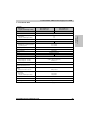
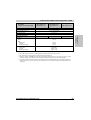
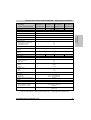
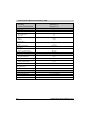
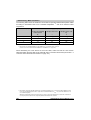
1. Manual history
Version
Date
Comment
0.10 Preliminary
16.03.2006
Changes / new features
• First version.
0.20 Preliminary
16.03.2006
Changes / new features
• Pin assignments for the line filter and regeneration choke added
• Pins assignments for additional auxiliary power supplies added
• Safety guidelines updated to include guidelines for handling ESD
0.21 Preliminary
30.03.2006
Changes / new features
• "Preliminary" deleted except in the manual history
• Images of the plug used for 8BVF.... changed (coding was not shown correctly)
0.22 Preliminary
16.05.2006
Changes / new features
• Dummy chapter with technical data added
• Wiring:
New overview images added, previous overview images deleted
0.23 Preliminary
19.05.2006
Changes / new features
• Order data in chapter 2 updated
Required and optional accessories added
• Overview images revised in chapter 5
0.24 Preliminary
04.07.2006
Changes / new features
• Additional shielding component set added (8SCS005.0000-00)
• Model numbers for plugs:
8TB3104.201A-00 --> 8TB3104.201A-10
8TB4104.202D-00 --> 8TB4104.206D-10
8TB4104.202N-00 --> 8TB4104.202N-10
• Technical data from exhibition brochures added
• Technical data:
Layout changes made to the required optional accessories
• Auxiliary supply modules:
New coding for X3 plug
0.25 Preliminary
06.07.2006
Changes / new features
• Auxiliary supply modules:
Numbering in the overview diagram for X3 plug corrected
0.26 Preliminary
18.07.2006
Changes / new features
• Technical data:
Revisions according to PA and discussion on July 05, 2006
New: EnDat plug-in module according to PA
New: Distribution of inverter modules according to PA
New: Additional auxiliary supply modules according to PA
New: Additional power supply modules according to PA
Table 1: Manual history
ACOPOSmulti User's Manual V 0.31
13
General information • Manual history
Version
Date
Comment
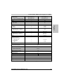
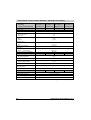
0.27 Preliminary
xx.08.2006
Changes / new features
• Technical data:
Revisions according to PA and Bernd on 04.08.06
Additional plug-in modules: EnDat 2.1, EnDat 2.2, SinCos
Inverter modules: Distribution of single and double-axis modules in different sections
0.28 Preliminary
xx.09.2006
Changes / new features
• Pin assignments:
Additional plug-in modules: EnDat 2.1, EnDat 2.2, SinCos
0.29 Preliminary
xx.11.2006
Changes / new features
• Technical data for inverter modules:
Cable length depending on the switching frequency
• Module images added
• Cross references from modules to plug-in modules
• Installation diagrams for mounting plate wall mounting
• Weights/dimensions updated for line filter and regeneration choke
• Figure index, Table index and Model number index added
0.30 Preliminary
31.01.2007
Changes / new features
• Installation:
Installation diagrams for inverter module wall mounting
• Wiring:
Insulation and high voltage test
• Wiring of plug-in modules:
Inner connection updated
• Technical data:
Indicator descriptions and LED status updated
• Dimensioning: Power connection updated
• Technical data, regeneration choke:
Screw connector added
• Technical data, inverter modules:
Nominal currents and derating updated (8BVI0014, 8BVI0028, 8BVI0055)
• Technical data, auxiliary supply modules:
Peak current (>4 s) 24 VDC internal system supply voltage changed
• Technical data, inverter:
Dependency of the motor cable length on the switching frequency documented
• Technical data, regeneration chokes:
8BVR0880H000.100-1 updated
• Technical data, line filter:
8BVF0880H000.000-1 updated
• Dimension diagrams and installation dimensions, wiring for regeneration chokes:
8BVR0880H000.100-1 updated
• Dimension diagrams and installation dimensions, wiring for line filter:
8BVF0880H000.000-1 updated
• Plug-in module pin assignments:
Plug name changed from X1 to X11
• Fan module pin assignments added
Table 1: Manual history (cont.)
14
ACOPOSmulti User's Manual V 0.31
Version
Date
Comment
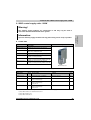
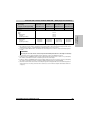
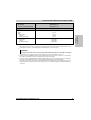
0.31 Preliminary
11.05.2007
Changes / new features
• Wiring of 8B0C0160HC00.A05-1:
Pin 4 of X2 connection wired incorrectly (+42V) --> corrected to +24V
• Technical data / wiring:
HIPERFACE plug-in module 8BAC0121.000-1 added
• Wiring / 8BAC0124.000-1
Inner connection modified / corrected
• Technical data 8BVI0440HxS0.000-1 / Required accessories:
Model number of plug for X5 connection added
• Wiring:
Section "Wired safety technology" added
• Wiring:
Section "Overview of the terminal cross sections" added
• Wiring / General information:
Section "General information" updated (shielding)
• Technical data for 8BVI..., 8BVP...
Electrical isolation of trigger inputs (8BVP, 8BVI) / Enable inputs (8BVP) corrected
• Technical data / wiring / mounting of 8BVR0440:
Changeover to 8BVR0110H000.100-1 and 8BVR0440H000.100-1
• Wiring of 8BVP0880 / 8BVI0880:
Mounting instructions added for X5 connection
• Wiring / General information:
Section "General information" updated (shielding)
• Technical data for 8BAC0120 / 0121 / 0122 / 0124:
Corrections / updates made to the technical data.
• Technical data for 8B0MxxxxHWxx / Dimensions:
Calculation of the width of the mounting plates modified/simplified
• Mounting / Wall mounting:
Diagrams modified according to the change in width of the mounting plates (n * 53.5 mm)
• General information / Safety notices:
The term "Servo drive" replaced with "drive system".
• Mounting / Cold-plate mounting, wall mounting:
Diagrams adjusted (calculation of the width of the mounting plates)
Chapter 1
General information
General information • Manual history
Table 1: Manual history (cont.)
Information:
B&R does its best to keep the printed versions of its user's manuals as current as
possible. However, any newer versions of the User's Manual are always available for
downloaded in electronic form (PDF) from the B&R homepage www.brautomation.com.
ACOPOSmulti User's Manual V 0.31
15
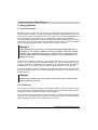
General information • Safety guidelines
2. Safety guidelines
2.1 General information
B&R drive systems and servo motors have been designed, developed and manufactured for
conventional use in industry. They were not designed, developed, and manufactured for any use
involving serious risks or hazards that could lead to death, injury, serious physical damage, or
loss of any kind without the implementation of exceptionally stringent safety precautions.
Such risks include in particular the use of these devices to monitor nuclear reactions in nuclear
power plants, as well as flight control systems, flight safety, the control of mass transportation
systems, medical life support systems, and the control of weapons systems.
Danger!
Drive systems and servo motors can have bare parts with voltages applied (e. g.
terminals) or hot surfaces. Additional sources of danger result from moving
machine parts. Improperly removing the required covers, inappropriate use,
incorrect installation or incorrect operation can result in severe personal injury or
damage to property.
All tasks, such as transport, installation, commissioning and service, are only permitted to be
carried out by qualified personnel. Qualified personnel are persons familiar with transport,
mounting, installation, commissioning and operation of the product and have the respective
qualifications (e. g. IEC 60364). National accident prevention guidelines must be followed.
The safety guidelines, connection descriptions (type plate and documentation), and limit values
listed in the technical data are to be read carefully before installation and commissioning and
must be observed.
Danger!
Handling drive systems and servo motors incorrectly can cause severe personal
injury or damage to property!
2.2 Intended use
Servo drives are components designed to be installed in electrical systems or machines. They
are not being used as intended unless the machine meets EG regulation 98/37/EG (machine
regulation) as well as regulation 89/336/EWG (EMC regulation).
Drive systems are only permitted to be operated directly on grounded, three-phase industrial
mains (TN, TT power mains). When using them in living areas, shops and small businesses,
additional filtering measures must be implemented by the user.
16
ACOPOSmulti User's Manual V 0.31
Danger!
Drive systems are not permitted to be operated directly on IT and TN-S mains with
a grounded phase conductor and protective ground conductor!
The technical data as well as the values for connection and environmental specifications can be
found on the type plate and in the user's manual. The connection and environmental
specifications must be met!
Danger!
Electronic devices are generally not failsafe. If the drive systems fails, the user is
responsible for making sure that the motor is placed in a secure state.
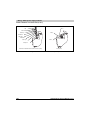
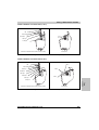
2.3 Protection against electrostatic discharges
Electrical components that are vulnerable to electrostatic discharge (ESD) must be handled
accordingly.
2.3.1 Packaging
Electrical components with housing do not require special ESD packaging, but must be handled
properly (see "Electrical components with housing").
Electrical components with housing must be protected by ESD-suitable packaging.
2.3.2 Guidelines for proper ESD handling
Electrical components with housing
•
Do not touch the contacts of connectors on connected cables.
•
Do not touch the contact tips on the circuit boards.
ACOPOSmulti User's Manual V 0.31
17
Chapter 1
General information
General information • Safety guidelines
General information • Safety guidelines
Electrical components without housing
In addition to "Electrical components with housing", the following also applies:
•
Any persons handling electrical components or devices that will be installed in the
electrical components must be grounded.
•
Components can only be touched on the small sides or on the front plate.
•
Components should always be stored in a suitable medium (ESD packaging, conductive
foam, etc.).
Metallic surfaces are not suitable storage surfaces!
•
Electrostatic discharges should be avoided on the components (e.g. through charged
plastics).
•
A minimum distance of 10 cm must be kept from monitors and TV sets.
•
Measurement devices and equipment must be grounded.
•
Measurement probes on potential-free measurement devices must be discharged on
sufficiently grounded surfaces before taking measurements.
Individual components
•
ESD protective measures for individual components are thoroughly integrated at B&R
(conductive floors, footwear, arm bands, etc.).
•
The increased ESD protective measures for individual components are not necessary for
our customers for handling B&R products.
2.4 Transport and storage
During transport and storage, devices must be protected from excessive stress (mechanical
load, temperature, humidity, aggressive atmosphere, etc.).
Drive systems contain components sensitive to electrostatic charges which can be damaged by
inappropriate handling. It is therefore necessary to provide the required safety precautions
against electrostatic discharges during installation or removal of drive systems.
2.5 Installation
The installation must take place according to the user's manual using suitable equipment and
tools.
Devices may only be installed without voltage applied and by qualified personnel. Before
installation, voltage to the switching cabinet should be switched off and prevented from being
switched on again.
The general safety regulations and national accident prevention guidelines (e. g. VBG 4) must
be observed when working with high voltage systems.
18
ACOPOSmulti User's Manual V 0.31
The electrical installation must be carried out according to the relevant guidelines (e. g. line cross
section, fuse, protective ground connection, also see chapter 4 "Dimensioning").
2.6 Operation
2.6.1 Protection against touching electrical parts
Danger!
To operate drive systems, it is necessary for certain parts to carry dangerous
voltages over 42 VDC. A life-threatening electrical shock could occur if you come
into contact with these parts. This could result in death, severe injury, or material
damage.
Before turning on a drive system, make sure that the housing is properly connected to ground
(PE rail). The ground connection must be made, even when testing the drive system or when
operating it for a short time!
Before turning the device on, make sure that all voltage-carrying parts are securely covered.
During operation, all covers and switching cabinet doors must remain closed.
Danger!
If an application uses safety functions integrated in the drive system, then the safety
functions must be fully validated before being turned on for the first time. This could
result in death, severe injury, or material damage.
Control and high power contacts can have voltage applied, even when the motor is not turning.
Touching the contacts when the device is switched on is not permitted.
Before working on drive systems, they must be disconnected from the power mains and
prevented from being switched on again.
Danger!
Dangerously High Voltage
Before beginning work, remove the supply voltage and wait 5 minutes to ensure that
the capacitors have discharged. Be sure to follow the regulations!
The connections for the signal voltages (5 to 30 V) found on the drive system are isolated
circuits. Therefore, the signal voltage connections and interfaces are only permitted to be
connected to devices or electrical components with sufficient isolation according to IEC 603644-41 or EN 50178 and which correspond to SELV / PELV.
ACOPOSmulti User's Manual V 0.31
19
Chapter 1
General information
General information • Safety guidelines
General information • Safety guidelines
Never remove the electrical connections from the drive system with voltage applied. In
unfavorable conditions, arcs can occur causing personal injury and damage to contacts.
2.6.2 Protection from dangerous movements
Danger!
Incorrect control of motors can cause unwanted and dangerous movements! Such
incorrect behavior can have various causes:
•
Incorrect installation or an error when handling the components
•
Incorrect or incomplete wiring
•
Defective devices (drive system, motor, position encoder, cable, brake)
•
Incorrect control (e. g. caused by software error)
Some of these causes can be recognized and prevented by the drive system using internal
monitoring. However, it is generally possible for the motor shaft to move every time the device
is switched on! Therefore protection of personnel and the machine can only be guaranteed using
higher level safety precautions.
The movement area of machines must be protected to prevent accidental access. This type of
protection can be obtained by using stabile mechanical protection such as protective covers,
protective fences, protective gates or photocells.
Removing, bridging or bypassing these safety features and entering the movement area is
prohibited.
A sufficient number of emergency stop switches are to be installed directly next to the machine.
The emergency stop equipment must be checked before commissioning the machine.
Remove shaft keys on free running motors or prevent them from being catapulted.
The holding brake built into the motors cannot prevent hoists from allowing the load to sink.
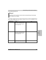
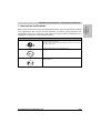
2.7 Organization of safety notices
The safety notices in this manual are organized as follows:
Safety notice
Description
Danger!
Disregarding the safety regulations and guidelines can be life-threatening.
Warning!
Disregarding the safety regulations and guidelines can result in severe injury or major damage to material.
Caution!
Disregarding the safety regulations and guidelines can result in injury or damage to material.
Information:
Important information for preventing errors.
Table 2: Description of the Safety Guidelines
20
ACOPOSmulti User's Manual V 0.31
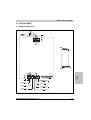
Technical data • Configuration of an ACOPOSmulti drive system
Chapter 2 • Technical data
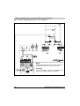
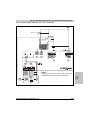
The ACOPOSmulti drive system consists of a mounting plate, different modules (power supply,
auxiliary supply and inverter modules) as well as a line filter and a regeneration choke.
The configuration significantly depends on the following factors:
•
Cooling method
•
Mean and maximum total power of the inverter and the peripheral supply (e.g. PLC,
actuators, motor holding brakes, sensors)
•
Mean and maximum power and current of the individual drive units (motors)
The configuration of an ACOPOSmulti drive system is done in 9 steps:
1) Determe cooling method
2) Determine the supply voltage range
3) Select the ACOPOSmulti inverter modules according to application requirements
4) Select the ACOPOSmulti plug-in modules for motor encoder and external axis encoder
according to the application requirements
5) If the ACOPOSmulti drive system should be expandable: Determine the number of additional
slots for other ACOPOSmulti modules
6) Select the ACOPOSmulti power supply module based on the total power required for the
ACOPOSmulti inverter modules (with a mains supply voltage of 3 x 220 VAC, select the next
larger power supply module)
7) Select the ACOPOSmulti auxiliary supply module based on the total power required for the
ACOPOSmulti inverter modules as well as the peripheral supply (e.g. PLC, actuators, motor
holding brakes, sensors)
8) Determine the total number of slots by adding the width units of all modules (including
optional slots)
9) Select the appropriate ACOPOSmulti mounting plate according to the total number of slots
ACOPOSmulti User's Manual V 0.31
21
Chapter 2
Technical data
1. Configuration of an ACOPOSmulti drive system
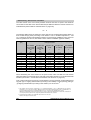
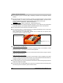
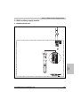
Technical data • Indications
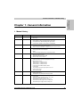
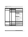
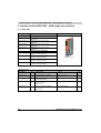
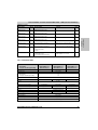
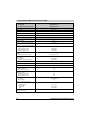
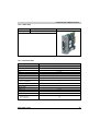
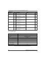
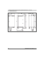
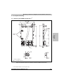
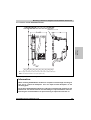
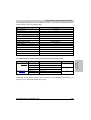
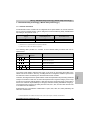
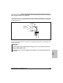
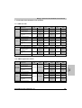
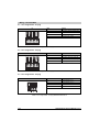
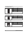
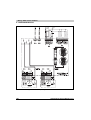
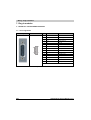
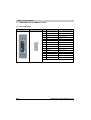
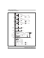
2. Indications
The indicators are located on the black cover of the respective ACOPOSmulti module.
2.1 8BVP power supply modules
Image
Indicator group
Label
Color
Function
Ethernet POWERLINK
R/E
Green/re
d
Ready/Error
L/D1
Green
Link / Data activity Port 1
L/D2
Green
Link / Data activity Port 2
RDY
Green
Ready
RUN
Orange
Run
ERR
Red
Error
Supply voltage
24V
Green
24 V OK
Encoder slot 1
UP
Orange
Encoder direction of rotation +
DN
Orange
Encoder direction of rotation -
Encoder slot 2
UP
Orange
Encoder direction of rotation +
DN
Orange
Encoder direction of rotation -
Inverter - Power
Table 3: Status LEDs, 8BVP power supply modules
22
ACOPOSmulti User's Manual V 0.31
Technical data • Indications
Indicator group
Label
Function
Description
Ethernet POWERLINK
R/E
Ready/Error
see LED status ETHERNET Powerlink
L/D1
Link / Data activity Port 1
Inverter - Power
L/D2
Link / Data activity Port 2
RDY
Ready
The module is operational and the power stage can be
enabled (operating system present and booted, no
permanent or temporary errors).
RUN
Run
The module' power stage is enabled.
ERR
Error
A permanent or temporary error exists on the module.
Chapter 2
Technical data
2.1.1 LED Status
Examples of permanent errors:
• Low level on an enable input
• Internal error on the device (e.g. IGBT heat sink
temperature sensor defective)
Examples of temporary errors:
• 24 VDC supply voltage exceeds the tolerance
range
• DC bus voltage exceeds the tolerance range
• Internal 15 VDC control voltage exceeds the
tolerance range
• Over-temperature on the module (IGBT junction,
heat sink)
• Powerlink network disturbance
• Over-temperature on the line filter / regeneration
choke (temperature sensor)
Supply voltage
24V
24 V OK
The 24V module supply voltage is within the tolerance
range
Encoder slot 1
UP
Encoder direction of rotation +
The encoder position of the connected encoder changed
in the positive direction. The faster the encoder position
changes, the brighter the LED is lit.
DN
Encoder direction of rotation -
The encoder position of the connected encoder changed
in the negative direction. The faster the encoder position
changes, the brighter the LED is lit
UP
Encoder direction of rotation +
See encoder slot 1
DN
Encoder direction of rotation -
Encoder slot 2
Table 4: LED status - 8BVP power supply module
ACOPOSmulti User's Manual V 0.31
23
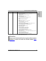
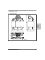
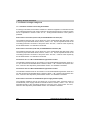
Technical data • Indications
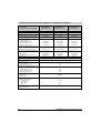
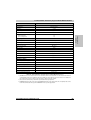
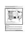
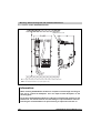
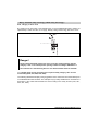
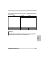
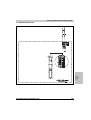
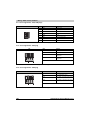
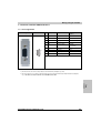
2.2 8B0C auxiliary supply module
Image
Indicator group
Label
Color
Supply voltage
24V
Green
42V1)
Function
24 V OK
42 V OK 1)
Overload
ERR
Red
Overload
24 V Out and 42 V Out 2)
24V
Green
24 V Out OK
42V1)
ERR
42 V Out OK 1)
Red
24 V Out error
42 V Out error 1)
Table 5: Status LEDs, 8B0C auxiliary supply modules
1) Only on 8B0C0160HC00.A01-1.
2) Only on 8B0C0160Hx00.001-1, 8B0C0160HC00.A01-1 and 8B0C0320Hx00.002-1.
2.2.1 LED Status
Indicator group
Label
Function
Description
Supply voltage
24V
24 V OK
The 24 VDC internal system supply voltage is within the
permissible tolerance
Overload
24 V Out and 42 V Out 2)
42V1)
42 V OK
The 42 VDC supply is within the permissible tolerance
ERR
Overload
The 24 VDC internal system supply voltage or 42 VDC
supply is outside of the permissible tolerance (overload,
over-temperature, short-circuit, etc)
One of the switchable 24 VDC outputs or 42 VDC outputs
is active and the output voltage is within the permissible
tolerance
The 24 VDC internal system supply voltage is within the
permissible tolerance 3)
24V
24 V Out OK
42V1)
42 V Out OK
ERR
24 V Out error
42 V Out error 1)
The 24 VDC internal system supply voltage or 42 VDC
supply is outside of the permissible tolerance (overload,
over-temperature, short-circuit, etc)
At least one of the switchable outputs is active and the
electronic fuse has been triggered on one or more
switchable outputs.
Table 6: LED status - 8B0C auxiliary supply modules
1) Only on 8B0C0160HC00.A01-1.
2) Only on 8B0C0160Hx00.001-1, 8B0C0160HC00.A01-1 and 8B0C0320Hx00.002-1.
3) Only on 8B0C0160Hx00.001-1 and 8B0C0320Hx00.002-1.
24
ACOPOSmulti User's Manual V 0.31
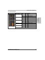
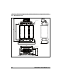
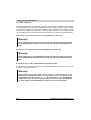
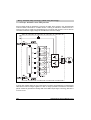
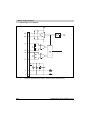
Technical data • Indications
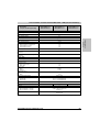
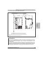
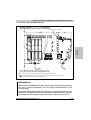
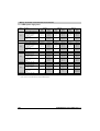
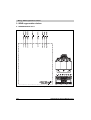
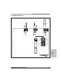
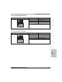
2.3 8BVI inverter modules
Image
Indicator group
Label
Color
Function
Ethernet POWERLINK
R/E
Green/re
d
Ready/Error
L/D1
Green
Link / Data activity Port 1
L/D2
Green
Link / Data activity Port 2
RDY
Green
Ready
RUN
Orange
Run
ERR
Red
Error
Supply voltage
24V
Green
24 V OK
Encoder slot 1
UP
Orange
Encoder direction of rotation +
DN
Orange
Encoder direction of rotation -
Encoder slot 2
UP
Orange
Encoder direction of rotation +
DN
Orange
Encoder direction of rotation -
Inverter axis 1
Chapter 2
Technical data
2.3.1 Single-axis modules
Table 7: Status LEDs, 8BVI inverter modules (single-axis modules)
ACOPOSmulti User's Manual V 0.31
25
Technical data • Indications
LED Status
Indicator group
Label
Function
Description
Ethernet POWERLINK
R/E
Ready/Error
see LED status ETHERNET Powerlink
L/D1
Link / Data activity Port 1
Inverter axis 1
L/D2
Link / Data activity Port 2
RDY
Ready
RUN
Run
The module' power stage is enabled.
ERR
Error
A permanent or temporary error exists on the module.
The module is operational and the power stage can be
enabled (operating system present and booted, no
permanent or temporary errors).
Examples of permanent errors:
• Low level on an enable input
• Internal error on the device (e.g. IGBT heat sink
temperature sensor defective)
• Motor feedback not connected or defective
• Motor temperature sensor not connected or
defective
Examples of temporary errors:
• 24 VDC supply voltage exceeds the tolerance
range
• DC bus voltage exceeds the tolerance range
• Internal 15 VDC control voltage exceeds the
tolerance range
• Over-temperature on the module (IGBT junction,
heat sink)
• Powerlink network disturbance
• IGBT current limit reached
• Over-temperature on the motor (temperature
sensor)
Supply voltage
24V
24 V OK
The 24V module supply voltage is within the tolerance
range
Encoder slot 1
UP
Encoder direction of rotation +
The encoder position of the connected encoder changed
in the positive direction. The faster the encoder position
changes, the brighter the LED is lit.
DN
Encoder direction of rotation -
The encoder position of the connected encoder changed
in the negative direction. The faster the encoder position
changes, the brighter the LED is lit
UP
Encoder direction of rotation +
See encoder slot 1
DN
Encoder direction of rotation -
Encoder slot 2
Table 8: LED status, 8BVI inverter modules (single-axis modules)
26
ACOPOSmulti User's Manual V 0.31
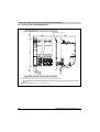
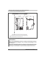
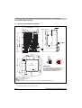
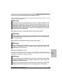
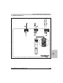
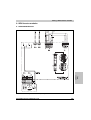
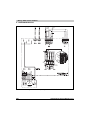
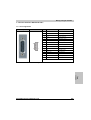
Technical data • Indications
Image
Indicator group
Label
Color
Function
Ethernet POWERLINK
R/E
Green/re
d
Ready/Error
L/D1
Green
Link / Data activity Port 1
L/D2
Green
Link / Data activity Port 2
RDY
Green
Ready
RUN
Orange
Run
Inverter axis 1
Inverter axis 2
ERR
Red
Error
RDY
Green
Ready
RUN
Orange
Run
ERR
Red
Error
Supply voltage
24V
Green
24 V supply voltage OK
Encoder Slot1
UP
Orange
Encoder direction of rotation +
DN
Orange
Encoder direction of rotation -
Encoder slot 2
UP
Orange
Encoder direction of rotation +
DN
Orange
Encoder direction of rotation -
Chapter 2
Technical data
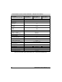
2.3.2 Two-axis modules
Table 9: Status LEDs, 8BVI inverter modules (two-axis modules)
ACOPOSmulti User's Manual V 0.31
27
Technical data • Indications
LED Status
Indicator group
Label
Function
Description
Ethernet POWERLINK
R/E
Ready/Error
see LED status ETHERNET Powerlink
L/D1
Link / Data activity Port 1
Inverter axis 1
L/D2
Link / Data activity Port 2
RDY
Ready
RUN
Run
The module' power stage is enabled.
ERR
Error
A permanent or temporary error exists on the module.
The module is operational and the power stage can be
enabled (operating system present and booted, no
permanent or temporary errors).
Examples of permanent errors:
• Low level on an enable input
• Internal error on the device (e.g. IGBT heat sink
temperature sensor defective)
• Motor feedback not connected or defective
• Motor temperature sensor not connected or
defective
Examples of temporary errors:
• 24 VDC supply voltage exceeds the tolerance
range
• DC bus voltage exceeds the tolerance range
• Internal 15 VDC control voltage exceeds the
tolerance range
• Over-temperature on the module (IGBT junction,
heat sink)
• Powerlink network disturbance
• IGBT current limit reached
• Over-temperature on the motor (temperature
sensor)
Inverter axis 2
RDY
Ready
RUN
Run
See inverter axis 1
ERR
Error
Supply voltage
24V
24 V OK
The 24V module supply voltage is within the tolerance
range
Encoder slot 1
UP
Encoder direction of rotation +
The encoder position of the connected encoder changed
in the positive direction. The faster the encoder position
changes, the brighter the LED is lit.
DN
Encoder direction of rotation -
The encoder position of the connected encoder changed
in the negative direction. The faster the encoder position
changes, the brighter the LED is lit
UP
Encoder direction of rotation +
See encoder slot 1
DN
Encoder direction of rotation -
Encoder slot 2
Table 10: LED status, 8BVI inverter modules (two-axis modules)
28
ACOPOSmulti User's Manual V 0.31
Technical data • Indications
2.4 LED Status
Indicator group
Label
Function
Description
Ethernet POWERLINK
R/E
Ready/Error
Red: The Powerlink node number of the module is 0
L/D1
Link / Data activity Port 1
L/D2
Link / Data activity Port 2
Chapter 2
Technical data
2.4.1 Ethernet POWERLINK
Table 11: See LED status ETHERNET Powerlink
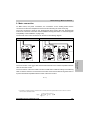
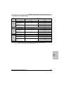
2.4.2 Status changes when booting the operating system loader
The following timing is used for the indication diagrams:
Block size:
125 ms
Repeats after:
3000 ms
Status
1.
LED
Boot procedure for basic hardware active
Display
RDY
RUN
ERR
2.
Configuration network active
RDY
RUN
ERR
3.
Waiting for network telegram
RDY
RUN
ERR
4.
Network communication active
RDY
RUN
ERR
Table 12: Status changes when booting the operating system loader
ACOPOSmulti User's Manual V 0.31
29
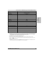
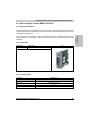
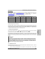
Technical data • Line filter 8BVF
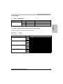
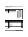
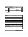
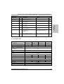
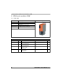
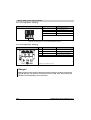
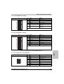
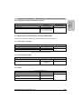
3. Line filter 8BVF
3.1 Order data
Model number
Short description
Image
Line filters
8BVF0110H000.000-1
ACOPOSmulti line filter 15A, 480V
8BVF0440H000.001-2
ACOPOSmulti line filter 44A, 480V, increased peak current
load capacity
8BVF0880H000.000-1
ACOPOSmulti line filter 89A, 480V
8BVF0440H000.001-2
Table 13: Order data - 8BVF line filter
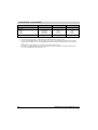
Required accessories
Model number
Amoun
t
Short description
Comment
Page
In preparation1)
1
Screw terminal 4 pins, 1 row RM7,62
Label 2: L1 L2 L3 PE
Coding N: 1100
Plug for X1 connection
171
8TB4104.202N-10 2)
1
Screw terminal 4 pins, 1 row RM10,16
Label 2: L1 L2 L3 PE
Coding N: 1100
Plug for X1 connection
171
In preparation1)
1
Screw terminal 4 pins, 1 row RM7,62
Label 2: L1´ L2´ L3´ PE
Coding D: 0011
Plug for X2 connection
171
8TB4104.206D-10 2)
1
Screw terminal 4 pins, 1 row RM10,16
Label 2: L1´ L2´ L3´ PE
Coding D: 0011
Plug for X2 connection
171
8TB2104.204A-00
1
Screw terminal 4 pins, 1 row RM5,08
Label 4: T- T+ F- F+
Coding A: 0000
Plug for X3 connection
171
Table 14: Required accessory for 8BVF line filters
1) Only for 8BVF0110H000.001-1.
2) Only for 8BVF0440H000.001-1.
30
ACOPOSmulti User's Manual V 0.31
Technical data • Line filter 8BVF
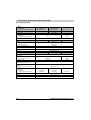
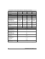
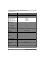
3.2 Technical data
Product ID
8BVF0110H000.000-1
8BVF0440H000.001-2
8BVF0880H000.000-1
General information
C-UL-US listed
In preparation
Cooling and mounting methods
Wall mounting
Power mains connection
3x220 to 3x480VAC ±10 %
Frequency
50 / 60 Hz ± 4%
Allocation to the power supply module
10 kW
32 kW
60 kW
Continuous current 1)
15 Aeff
44 Aeff
89 Aeff
Peak current < 10 s
In preparation
110 Aeff
162 Aeff
Reduction of continuous current according to
the ambient temperature above 40 °C
In preparation
In preparation
In preparation
Power loss at rated current
In preparation
250 W
470 W
Line filter according to EN61800-3-A11
second environment (Limits from CISPR11,
Group 2, Class A) 2)
Yes
Design
L1, L2, L3, PE and L1´, L2´, L3´, PE
PU
Shield connection
on the mains
on the device
Terminal connection cross section
Flexible and fine wire lines with wire tip
sleeves
UL/cUlus
CSA
Terminal outer cross-section dimension of
the shield connection
Chapter 2
Technical data
Mains input voltage
Connectors
Threaded bolt M5
Feed-through terminals
No
No
Yes 3)
No
Yes 3)
0.5 - 6 mm²
0.5 - 16 mm²
10 - 50 mm²
22 - 10
22 - 10
20 - 6
20 - 6
6-1/0
6-1/0
12 - 22 mm
23 - 35 mm
32 - 50 mm
Temperature sensor
Temperature sensor type
EPCOS B59100M1155A070
Design
T+, T-
Connectors
Fan connection
Design
F+, F-
Connectors
Table 15: Technical data - 8BVF line filters
ACOPOSmulti User's Manual V 0.31
31
Technical data • Line filter 8BVF
Product ID
8BVF0110H000.000-1
8BVF0440H000.001-2
8BVF0880H000.000-1
Dimensions
Width
Height
Depth
In preparation
In preparation
In preparation
135 mm
378 mm
212 mm
175 mm
436 mm
212 mm
Weight
In preparation
15 kg
23.5 kg
Mechanical characteristics
Table 15: Technical data - 8BVF line filters (cont.)
1) Valid in the following conditions: 40 °C ambient temperature, installation altitude< 500 m above sea level.
2) To avoid exceeding the EMC limit values, the total length of all motor cables for each mounting plate (and therefore each line filter)
should be limited to a maximum of 900 m. The cable length between the line filter and the power supply module is limited to a maximum
of 5 m.
The maximum motor cable length per motor connection is also limited (see inverter modules).
3) The cable does not require shielding up to a total cable length between the line filter, regeneration choke and power supply module of
3 m. Please contact B&R when using cable lengths > 3 m.
32
ACOPOSmulti User's Manual V 0.31
Technical data • 8BVR regeneration chokes
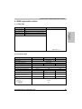
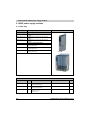
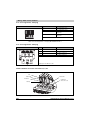
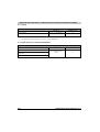
4. 8BVR regeneration chokes
4.1 Order data
Model number
Short description
Image
8BVR0110H000.100-1
ACOPOSmulti regeneration choke 15A, 480V, terminals
8BVR0440H000.100-1
ACOPOSmulti regeneration choke 44A, 480V, terminals
8BVR0880H000.100-1
ACOPOSmulti regeneration choke 89A, 480V, terminals
Chapter 2
Technical data
Regeneration choke
8BVR0440H000.100-1
Table 16: Order data - 8BVR regeneration chokes
4.2 Technical data
Product ID
8BVR0110H000.100-1
8BVR0440H000.100-1
8BVR0880H000.100-1
General information
C-UL-US listed
In preparation
Cooling and mounting methods
Wall mounting
Power mains connection
Mains input voltage
3x220 to 3x480VAC ±10 %
Frequency
50 / 60 Hz ± 4%
Allocation to the power supply module
10 kW
32 kW
60 kW
Continuous current 1)
15 Aeff
44 Aeff
89 Aeff
Peak current < 10 s
In preparation
110 Aeff
162 Aeff
Reduction of continuous current according to
the ambient temperature above 40 °C
In preparation
In preparation
In preparation
Power loss at rated current
In preparation
330 W
470 W
Design
U1, V1, W1
U2, V2, W2
Shield connection 2)
on the mains
on the device
Terminals
Terminals
No
No
Table 17: Technical data - 8BVR regeneration chokes
ACOPOSmulti User's Manual V 0.31
33
Technical data • 8BVR regeneration chokes
Product ID
8BVR0110H000.100-1
Terminal connection cross section
Flexible and fine wire lines with wire tip
sleeves
UL/cUlus
CSA
Terminal outer cross-section dimension of
the shield connection
8BVR0440H000.100-1
8BVR0880H000.100-1
1.5 - 16 mm²
2.5 - 35 mm²
18 - 4
18 - 4
12 - 1
12 - 2
---
Temperature sensor
Temperature sensor type
EPCOS B59100M1155A070
Design
T+, T-
Terminals
Mechanical characteristics
Dimensions
Width
Height
Depth
In preparation
In preparation
In preparation
240 mm
280 mm
125 mm
290 mm
406 mm
135 mm
Weight
In preparation
24.1 kg
40.2 kg
Table 17: Technical data - 8BVR regeneration chokes (cont.)
1) Valid in the following conditions: 40 °C ambient temperature, installation altitude< 500 m above sea level.
2) The cable does not require shielding up to a total cable length between the line filter, regeneration choke and power supply module of
3 m. Please contact B&R when using cable lengths > 3 m.
34
ACOPOSmulti User's Manual V 0.31
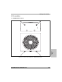
Technical data • 8B0M mounting plates
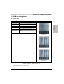
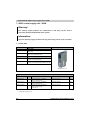
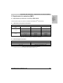
5. 8B0M mounting plates
5.1 Order data
Model number1)
Short description
Image
Wall mounting
8B0MnnnnHW00.000-1 2) ACOPOSmulti mounting plate with backplane nnnn slots,
800V, wall mounting, 75mm² and 22mm², complete
8B0MnnnnHC00.000-1
ACOPOSmulti mounting plate with backplane, nnnn slots,
800V, cold plate mounting, 75mm² and 22mm², complete
8B0MnnnnHF00.000-1 3)
ACOPOSmulti mounting plate with backplane nnnn slots,
800V, feed-through mounting, 75mm² and 22mm², complete
Chapter 2
Technical data
Cold plate mounting
Feed-through mounting
8B0MnnnnHW00.000-1
8B0MnnnnHC00.000-1
8B0MnnnnHF00.000-1
Table 18: Order data - 8B0M mounting plates
1) The desired number of slots must be specified in the model number by nnnn (0160 equals 16 slots).
2) Only mounting plates with 2 or more slots are possible.
3) The number of slots must be a multiple of 4.
ACOPOSmulti User's Manual V 0.31
35
Technical data • 8B0M mounting plates
SOptional accessories
Model number
Amount Short description
Comment
Page
8B0M0040HFF0.000-1 1)
---
ACOPOSmulti fan module for mounting plate,
4 slots, 800V, feed-through mounting
One fan module is required for every 4 slots
X67CA0P20.xxxx 1) 2)
1
Power connection cable, xxxx m
24 VDC connection cable for
ACOPOSmulti fan modules
8B0M0040HFF0.000-1
max. 2
Power connection cable, 0.2 m
24 VDC connection cable between two
ACOPOSmulti fan modules
8B0M0040HFF0.000-1
X67CA0P00.0002 1)
Table 19: Optional accessory for 8B0M mounting plates
1) Only for 8B0MnnnnHF00.000-1.
2) The cable length is specified in decimeters by xxxx (0010 equals a cable length of 1 m).
5.2 Technical data
Product ID 1)
8B0MnnnnHW00.000-1
8B0MnnnnHC00.000-1
8B0MnnnnHF00.000-1
Wall mounting
Cold plate mounting
Feed-through mounting
nnnn 2)
27
nnnn
27
nnnn 3)
27
General information
C-UL-US listed
In preparation
Cooling and mounting methods
Number of slots
Max.
DC bus
Voltage
Max.
800 VDC
900 VDC
Continuous power 4)
200 kW
Reduction of continuous current according to
the ambient temperature above 40 °C
In preparation
Reduction of continuous power depending on
altitude
Starting at 500 m above sea level
In preparation
In preparation
20 kW per 1,000 m
Cross section
DC+, DCPU
72 mm²
72 mm²
24 VDC auxiliary supply
Voltage
25 VDC ± 1.6 %
Continuous power 4)
1500 W
Reduction of continuous current according to
the ambient temperature above 40 °C
Reduction of continuous power depending on
altitude
Starting at 500 m above sea level
Cross section
24 VDC, COM
In preparation
In preparation
In preparation
150 W per 1000 m
21.3 mm²
Table 20: Technical data - 8B0M mounting plates
36
ACOPOSmulti User's Manual V 0.31
Technical data • 8B0M mounting plates
Product ID 1)
8B0MnnnnHW00.000-1
8B0MnnnnHC00.000-1
8B0MnnnnHF00.000-1
Operational conditions
Ambient temperature during operation
Max. ambient temperature 5)
0 to 40 °C
+55 °C
Relative humidity during operation
5 to 95 %, non-condensing
0 to 500 m
4,000 m
Installation at altitudes above sea level
Maximum installation altitude 6)
Degree of pollution according to EN 60664-1
2 (non-conductive material)
III
EN 60529 protection
IP20
Chapter 2
Technical data
Overvoltage category according to
IEC 60364-4-443:1999
IP64
Fan module IP54
(8B0M0040HFF0.000-1)
Storage and transport conditions
Storage temperature
-25 to +55 °C
Relative humidity during storage
5 to 95 %, non-condensing
Transport temperature
-25 to +70 °C
Relative humidity during transport
95 % at +40 °C
Mechanical characteristics
Dimensions 7)
Width
Height
Depth
(n * 53.5) mm
385 mm
13.5 mm
(37 + n * 53.5) mm
378 mm
17 mm
(64 + n * 53.5) mm
378 mm
14 mm
Weight
In preparation
(0.94 * number of slots) kg
(1.6 * number of slots) kg
Table 20: Technical data - 8B0M mounting plates (cont.)
1)
2)
3)
4)
5)
The desired number of slots must be specified in the model number by nnnn (0160 equals 16 slots).
Only mounting plates with 2 or more slots are possible.
The number of slots must be a multiple of 4.
Valid in the following conditions: 40 °C ambient temperature, installation altitude< 500 m above sea level.
Continuous operation of ACOPOSmulti mounting plates at an ambient temperature ranging from 40 °C to max. 55 °C is possible (taking
the continuous power reductions listed into consideration).
6) Continuous operation of ACOPOSmulti mounting plates at altitudes ranging from 500 m to 4000 m above sea level is possible (taking
the continuous power reductions listed into consideration). Additional requirements are to be arranged with B&R.
7) The dimensions define the actual size of the mounting plate. Make sure to leave additional space above and below the mounting plate
for mounting, connections and air circulation (see 2 "Dimension diagrams and installation dimensions" on page 96).
ACOPOSmulti User's Manual V 0.31
37
Technical data • 8BVP power supply modules
6. 8BVP power supply modules
6.1 Order data
Model number
Short description
Image
Wall mounting
8BVP0110HW00.000-1
ACOPOSmulti power supply module 11A, 800V, wall
mounting
8BVP0440HW00.000-1
ACOPOSmulti power supply module 44A, 800V, wall
mounting
8BVP0880HW00.000-1
ACOPOSmulti power supply module 88A, 800V, wall
mounting
8BVP0110HC00.000-1
ACOPOSmulti power supply module 11A, 800V, cold plate or
feed-through mounting
8BVP0440HC00.000-1
ACOPOSmulti power supply module 11A, 800V, cold plate or
feed-through mounting
8BVP0880HC00.000-1
ACOPOSmulti power supply module 88A, 800V, cold plate or
feed-through mounting
Cold plate or feed-through mounting
8BVP0110HC00.000-1
8BVP0880HC00.000-1
Table 21: Order data - 8BVP power supply modules, 10kW ... 60kW
Required accessories
Model number
Amoun
t
Short description
Comment
Page
8TB2106.2010-00
1
Screw terminal 6 pins, 1 row RM5,08
Label 1: numbered serially
Plug for X1 connection
178
8TB2108.2010-00
1
Screw terminal 8 pins, 1 row RM5,08
Label 1: numbered serially
Plug for X2 connection
178
8TB2104.204A-00
1
Screw terminal 4 pins, 1 row RM5,08
Label 4: T- T+ F- F+
Coding A: 0000
Plug for X4A connection
178
Table 22: Required accessories - 8BVP power supply modules (10kW ... 60kW)
38
ACOPOSmulti User's Manual V 0.31
Technical data • 8BVP power supply modules
Required accessories
Model number
Amoun
t
Short description
Comment
Page
In preparation1)
1
Screw terminal 4 pins, 1 row RM10,16
Label 2: L1 L2 L3 PE
Coding N: 1100
Plug for X5A connection
178
In preparation2)
1
Screw terminal 4 pins, 1 row RM10,16
Label 2: L1 L2 L3 PE
Coding N: 1100
Plug for X5A connection
178
Chapter 2
Technical data
Table 22: Required accessories - 8BVP power supply modules (10kW ... 60kW) (cont.)
1) Only for 8BVP0110Hx00.000-1.
2) Only for 8BVP0440Hx00.000-1.
Optional accessories
Model number
Amoun
t
Short description
Comment
Page
8BAC0120.000-1
max. 2
ACOPOSmulti plug-in module,
EnDat 2.1 interface
---
78
8BAC0120.001-1
max. 2
ACOPOSmulti plug-in module,
EnDat 2.2 interface
---
85
8BAC0122.000-1
max. 2
ACOPOSmulti plug-in module,
Resolver interface
---
87
8BAC0124.000-1
max. 2
ACOPOSmulti plug-in module,
SinCos interface
---
91
8SCS005.0000-00
Up to 2
Shield component set consisting of:
1 slot cover shield sheet
Shield sheet for covering free plug-in
module slots
---
8SCS002.0000-00
1
Shield component set consisting of:
1 clamping plate
2 clamps D 4-13.5mm
2 screws
Shield component set for I/O cable with a
cable diameter of 4 - 13.5 mm
---
8SCS000.0000-00 1)
1
Shield component set consisting of:
1 shield plate 1x type 0
1 hose clamp, W 9mm, D 12-22mm
Shield component set for power cables with
a diameter of 12 - 22 mm
---
In preparation2)
1
Shield component set consisting of:
1 shield plate 1x type 0
1 hose clamp, W 9mm, D 23-35mm
Shield component set for power cables with
a diameter of 23 - 35 mm
---
8SCS003.0000-00 3)
1
Shield component set consisting of:
1 shield mounting plate, 4x, 45°
8 screws
Base plate for mounting shield component
set 8SCS001.0000-00 or 8SCS004.000000
---
8SCS004.0000-00 3)
1
Shield component set consisting of:
1 shield plate, 4x, type 0
2 hose clamps, W 9mm, D 32-50mm
Shield component set for power cables with
a diameter of 32 - 50 mm
---
8SCS001.0000-00 3)
3
Shield component set consisting of:
1 shield plate, 4x, type 1
1 hose clamp, W 9mm, D 12-22mm
Shield component set for individual wires
with a diameter of 12 - 22 mm
---
Table 23: Optional accessories - 8BVP power supply modules (10kW ... 60kW)
1) Only for 8BVP0110Hx00.000-1.
2) Only for 8BVP0440Hx00.000-1.
3) Only for 8BVP0880Hx00.000-1.
ACOPOSmulti User's Manual V 0.31
39
Technical data • 8BVP power supply modules
6.2 Technical data
Product ID
Wall mounting
Cold plate or feed-through mounting
8BVP0110HW00.000-1
8BVP0110HC00.000-1
8BVP0440HW00.000-1
8BVP0440HC00.000-1
8BVP0880HW00.000-1
8BVP0880HC00.000-1
General information
C-UL-US listed
In preparation
Available cooling and mounting methods
Wall mounting
Cold plate or feed-through mounting
Module width
Yes
Yes
Yes
Yes
Yes
Yes
1
2
4
Power mains connection
Mains input voltage 1)
3x220 to 3x480VAC ±10 %
System configuration
TT, TN-S, TN-C-S
Frequency
50 / 60 Hz ± 4%
Installed load
In preparation
Power loss at max. device power
In preparation
Starting current at 400 VAC
In preparation
Switch-on interval
> 10 s
Max. chargeable DC bus voltage
2 mF
Rated switching frequency
4 mF
Integrated line filter according to EN 61800-3A11 second environment (limits from
CISPR11, group 2, class A)
No
Integrated regeneration choke
No
Capable of regeneration
Yes
Power Factor Control (PFC)
Yes
Design
L1, L2, L3, PE
PU
Shield connection
Terminal connection cross sections
Flexible and fine wire lines
with wire tip sleeves
Approbation data
UL/C-UL-US
CSA
Terminal cable outer-cross-section
dimension of the shield connection
8 mF
5 kHz
Connectors
Threaded bolt M5
Yes 2)
Connectors
Threaded bolt M5
Yes 2)
Threaded bolt M8
No
Yes 2)
0.5 - 6 mm²
0.5 - 16 mm²
6 - 50 mm² 3)
22 - 10
22 - 10
20 - 6
20 - 6
In preparation
In preparation
12 - 22 mm
23 - 35 mm
32 - 50 mm
Table 24: Technical data - 8BVP power supply modules (10kW ... 60kW)
40
ACOPOSmulti User's Manual V 0.31
Technical data • 8BVP power supply modules
Product ID
Wall mounting
Cold plate or feed-through mounting
8BVP0110HW00.000-1
8BVP0110HC00.000-1
8BVP0440HW00.000-1
8BVP0440HC00.000-1
8BVP0880HW00.000-1
8BVP0880HC00.000-1
DC bus connection
800 VDC
900 VDC
Continuous power (supply and regeneration)
10 kW
25 kW
60 kW
Reduction of continuous power according to
the ambient temperature above 40 °C
In preparation
In preparation
In preparation
Reduction of continuous power depending on
altitude
starting at 500 m above sea level
1 kW per 1,000 m
2.5 kW per 1,000 m
6 kW per 1,000 m
Reduction of continuous power depending on
cooling method
Wall mounting
Cold plate or feed-through mounting
In preparation
In preparation
In preparation
In preparation
In preparation
In preparation
4)
Peak power (supply and regeneration)
Power loss at max. device power
25 kW
50 kW
121 kW
In preparation
In preparation
In preparation
DC bus capacitance
In preparation
Protective measures
Overload protection
Short circuit and ground fault
Chapter 2
Technical data
Voltage
Max.
1650 µF
Yes
No
Design
ACOPOSmulti backplane
24 VDC supply 5)
Input voltage
25 VDC ± 1.6 %
Input capacitance
In preparation
Power consumption
4.7 µF
In preparation
Design
ACOPOSmulti backplane
Line filter fan connection
Output voltage
24V +5.8 / -0.1 %
Continuous current
2.1 A
4.2 A
Protective measures
Overload and short circuit protection
Cable breakage monitoring
Undervoltage monitoring
Yes
No
No
Max. over-current limitation
8A
Table 24: Technical data - 8BVP power supply modules (10kW ... 60kW) (cont.)
ACOPOSmulti User's Manual V 0.31
41
Technical data • 8BVP power supply modules
Product ID
Wall mounting
Cold plate or feed-through mounting
8BVP0110HW00.000-1
8BVP0110HC00.000-1
8BVP0440HW00.000-1
8BVP0440HC00.000-1
8BVP0880HW00.000-1
8BVP0880HC00.000-1
Trigger inputs
Number of inputs
2
Wiring
Sink
Electrical isolation
Input - Power supply module
Input - Input
Yes
Yes
Input voltage
Rated
Maximum
24 VDC
30 VDC
Switching threshold
LOW
HIGH
Input current at rated voltage
Switching delay
Positive edge
Negative edge
Modulation compared to ground potential
<5 V
>15 V
approx. 10 mA
52 µs ± 0.5 µs (digitally filtered)
53 µs ± 0.5 µs (digitally filtered)
Max. ±38 V
24 V Out
Amount
2
Output voltage
DC bus voltage 260 ... 315 VDC
DC bus voltage 315 ... 900 VDC
Fuse protection
25 VDC * (DC bus voltage / 315)
24 VDC ± 6 %
500 mA (slow-blow) electronic,
automatic reset
Operational conditions
Ambient temperature during operation
Max. ambient temperature 6)
Relative humidity during operation
Installation at altitudes above sea level
Maximum installation altitude 7)
Degree of pollution according to EN 60664-1
Overvoltage category according to
IEC 60364-4-443:1999
EN 60529 protection
0 to 40 °C
+55 °C
5 to 95 %, non-condensing
0 to 500 m
4,000 m
2 (non-conductive material)
III
IP20
Storage and transport conditions
Storage temperature
Relative humidity during storage
Transport temperature
Relative humidity during transport
-25 to +55 °C
5 to 95 %, non-condensing
-25 to +70 °C
95 % at +40 °C
Table 24: Technical data - 8BVP power supply modules (10kW ... 60kW) (cont.)
42
ACOPOSmulti User's Manual V 0.31
Technical data • 8BVP power supply modules
Product ID
Wall mounting
Cold plate or feed-through mounting
8BVP0110HW00.000-1
8BVP0110HC00.000-1
8BVP0440HW00.000-1
8BVP0440HC00.000-1
8BVP0880HW00.000-1
8BVP0880HC00.000-1
53 mm
317 mm
106.5 mm
317 mm
213.5 mm
317 mm
263 mm
212 mm
209 mm
263 mm
212 mm
209 mm
263 mm
212 mm
209 mm
Dimensions 8)
Width
Height
Depth
Wall mounting
Cold-plate
Feed-through mounting
Weight
Wall mounting
Cold-plate
Feed-through mounting
In preparation
In preparation
In preparation
Chapter 2
Technical data
Mechanical characteristics
In preparation
approx. 7.6 kg
approx. 7.6 kg
Table 24: Technical data - 8BVP power supply modules (10kW ... 60kW) (cont.)
1) When operating with 3 x 220 VAC to 3 x 400 VAC, the continuous power is derated (250 W per volt).
2) The cable does not require shielding up to a total cable length between the line filter, regeneration choke and power supply module of
3 m. Please contact B&R when using cable lengths > 3 m.
3) The connection is made with cable lugs using an M8 threaded bolt.
4) Valid in the following conditions: 40 °C ambient temperature, installation altitude< 500 m above sea level.
5) In the power supply modules a DC bus power supply is integrated for the electronic supply. The 24 VDC supply from the ACOPOSmulti
backplane only feeds the +24 VDC of the trigger inputs and the encoder power supplies on the encoder modules.
6) Continuous operation of ACOPOSmulti power supply modules at ambient temperatures ranging from 40 °C to max. 55 °C is possible
(taking the continuous current reductions listed into consideration), but results in a shorter lifespan.
7) Continuous operation of ACOPOSmulti power supply modules at altitudes ranging from 500 m to 4000 m above sea level is possible
(taking the continuous current reductions listed into consideration). Additional requirements are to be arranged with B&R.
8) The dimensions define the true device dimensions including the respective mounting plate. Make sure to leave additional space above
and below the device for mounting, connections and air circulation (see section 2 "Dimension diagrams and installation dimensions"
on page 96).
ACOPOSmulti User's Manual V 0.31
43
Technical data • 8B0C control supply unit - 400W
7. 8B0C control supply unit - 400W
Warning!
The auxiliary supply modules are components of and may only be used in
connection with the ACOPOSmulti drive system.
Information:
Up to five auxiliary supply modules with any power rating can be set up in parallel.
7.1 Order data
Model number
Short description
Image
Wall mounting
8B0C0160HW00.000-1
ACOPOSmulti auxiliary supply module 16A, 800V,
Wall mounting
8B0C0160HW00.001-1
ACOPOSmulti auxiliary supply module 16A, 800V,
Wall mounting, 24VOut 1x16A, 1x5A
8B0C0160HC00.000-1
ACOPOSmulti auxiliary supply module 16A, 800V,
Cold plate or feed-through mounting
8B0C0160HC00.001-1
ACOPOSmulti auxiliary supply module 16A, 800V,
Cold plate or feed-through mounting, 24VOut 1x16A, 1x5A
Cold plate or feed-through mounting
8B0C0160HC00.001-1
Table 25: Order data for 8B0C control supply units 400W
Required accessories
Model number
Amoun
t
Short description
Comment
Page
8TB2106.2010-00
1
Screw terminal 6 pins, 1 row RM5,08
Label 1: numbered serially
Plug for X1 connection
183
8TB2104.2010-00 1)
1
Screw terminal 4 pins, 1 row RM5,08
Label 1: numbered serially
Plug for X2 connection
185
8TB3104.201M-10 1)
1
Screw terminal 4 pins, 1 row RM7,62
Label 1: numbered serially
Coding M: 1011
Plug for X3 connection
185
Table 26: Required accessories for 8B0C auxiliary supply modules 400W
1) Only for 8B0C0160Hx00.001-1.
44
ACOPOSmulti User's Manual V 0.31
Technical data • 8B0C control supply unit - 400W
7.2 Technical data
Product ID
Wall mounting
Cold plate or feed-through mounting
8B0C0160HW00.000-1
8B0C0160HC00.000-1
8B0C0160HW00.001-1
8B0C0160HC00.001-1
General information
In preparation
Available cooling and mounting methods
Wall mounting
Cold plate or feed-through mounting
Module width
Yes
Yes
Chapter 2
Technical data
C-UL-US listed
1
DC bus connection
Voltage
Operating range in continuous operation
Full continuous power
800 VDC
260 - 900 VDC
315 - 900 VDC
Continuous power consumption
Max. 470 W
Power loss at max. device power
In preparation
DC bus capacitance
In preparation
Design
ACOPOSmulti backplane
24 VDC output
Continuous power 1)
400 W
Output voltage
DC bus voltage 260 ... 315 VDC
DC bus voltage 315 ... 900 VDC
Continuous current
25 VDC * (DC bus voltage / 315)
24 VDC ± 6 %
16 ADC
Reduction of continuous power according to
ambient temperature above 40 °C
No reduction
Reduction of continuous power depending on
altitude
Starting at 500 m above sea level
40 W per 1000 m
Reduction of continuous power depending on
cooling method
Wall mounting
Cold plate or feed-through mounting
In preparation
In preparation
Startup delay
Max. 1 sec.
Startup time
Approx. 5 - 20 ms
Residual ripple
Typ. 50 mVSS
Table 27: Technical data for 8B0C control supply units 400W
ACOPOSmulti User's Manual V 0.31
45
Technical data • 8B0C control supply unit - 400W
Product ID
Wall mounting
Cold plate or feed-through mounting
8B0C0160HW00.000-1
8B0C0160HC00.000-1
8B0C0160HW00.001-1
8B0C0160HC00.001-1
24 VDC internal system supply voltage
Output voltage
25 VDC ± 1.6 %
Peak current (< 4 s)
DC bus voltage (UDC): 350 ... 900 VDC
21 ADC
Protective measures
Open circuit protection
Overload protection
Short circuit protection
Feedback protection
Over-temperature protection
Dielectric strength to ground
Output / input isolation
Yes
Yes
Yes
Max. 26 VDC (also when turned off)
Yes
±50 VDC
SELV / PELV requirements
Design
ACOPOSmulti backplane
24 VDC Out
Output voltage
DC bus voltage 260 ... 315 VDC
DC bus voltage 315 ... 900 VDC
-----
25 VDC * (DC bus voltage / 315)
24 VDC ± 6 %
Peak current (< 4 s) over the total operating
range of the DC bus voltage.
---
---
Protection of 24 VDC Out 1 output
---
16 A (slow-blow) electronic,
automatic reset
Protection of 24 VDC Out 2 output
---
5 A (slow-blow) electronic,
automatic reset
Protective measures
Open circuit protection
Overload protection
Short circuit protection
Feedback protection
---------
Yes
Yes
Yes
Max. 35 VDC (also when turned off)
Yes
±50 VDC
SELV / PELV requirements
Over-temperature protection
Dielectric strength to ground
Output / input isolation
Design
24 VDC, COM
---------
Connectors
Terminal connection cross section of 24 VDC
Out 1 output
Flexible and fine wire lines
with wire tip sleeves
Approbation data
UL/C-UL-US
CSA
---
0.5 - 6 mm²
-----
22 - 10
22 - 10
Terminal connection cross section of 24 VDC
Out 2 output
Flexible and fine wire lines
with wire tip sleeves
Approbation data
UL/C-UL-US
CSA
---
0.2 - 2.5 mm²
-----
22 - 12
22 - 12
Table 27: Technical data for 8B0C control supply units 400W (cont.)
46
ACOPOSmulti User's Manual V 0.31
Technical data • 8B0C control supply unit - 400W
Product ID
Wall mounting
Cold plate or feed-through mounting
8B0C0160HW00.000-1
8B0C0160HC00.000-1
8B0C0160HW00.001-1
8B0C0160HC00.001-1
Wiring
---
Sink
Electrical isolation
Input - 24 VDC
---
Yes
Modulation compared to ground potential
---
Max. ±50 V
Input voltage
Rated
Maximum
-----
24 VDC
30 VDC
Switching threshold
LOW (24 VDC Out 1 is switched on)
HIGH (24 VDC Out 1 is switched off)
-----
<5 V
>15 V
Input current at rated voltage
---
approx. 10 mA
Switching delay
ON (24 VDC Out 1 is switched on)
OFF (24 VDC Out 1 is switched off) 2)
-----
Max. 25 ms
Max. 0.25 ms
Design
---
Connectors
Terminal connection cross section of the 24
VDC Out 1 control input
Flexible and fine wire lines
with wire tip sleeves
Approbation data
UL/C-UL-US
CSA
---
0.2 - 2.5 mm²
-----
30 - 12
22 - 12
Chapter 2
Technical data
24 VDC Out 1 controller input
Operational conditions
Ambient temperature during operation
Max. ambient temperature
Relative humidity during operation
Installation at altitudes above sea level
Maximum installation altitude 3)
Degree of pollution according to EN 60664-1
Overvoltage category according to
IEC 60364-4-443:1999
EN 60529 protection
0 to 40 °C
+55 °C
5 to 95 %, non-condensing
0 to 500 m
4,000 m
2 (non-conductive material)
III
IP20
Storage and transport conditions
Storage temperature
-25 to +55 °C
Relative humidity during storage
Transport temperature
5 to 95 %, non-condensing
-25 to +70 °C
Relative humidity during transport
95 % at +40 °C
Table 27: Technical data for 8B0C control supply units 400W (cont.)
ACOPOSmulti User's Manual V 0.31
47
Technical data • 8B0C control supply unit - 400W
Product ID
Wall mounting
Cold plate or feed-through mounting
8B0C0160HW00.000-1
8B0C0160HC00.000-1
8B0C0160HW00.001-1
8B0C0160HC00.001-1
Mechanical characteristics
Dimensions 4)
Width
Height
Depth
Wall mounting
Cold-plate
Feed-through mounting
Weight
Wall mounting
Cold-plate
Feed-through mounting
53 mm
317 mm
263 mm
212 mm
209 mm
In preparation
approx. 2.6 kg
approx. 2.6 kg
Table 27: Technical data for 8B0C control supply units 400W (cont.)
1) Valid in the following conditions: 55 °C ambient temperature, installation altitude< 500 m above sea level.
2) The output and any connected loads are not actively discharged when switching off.
3) Continuous operation of ACOPOSmulti control supply units at altitudes ranging from 500 m to 4000 m above sea level is possible
(taking the continuous power reductions listed into consideration). Additional requirements are to be arranged with B&R.
4) The dimensions define the true device dimensions including the respective mounting plate. Make sure to leave additional space above
and below the device for mounting, connections and air circulation (see section 2 "Dimension diagrams and installation dimensions"
on page 96).
48
ACOPOSmulti User's Manual V 0.31
Technical data • 8B0C control supply units - 800W
8. 8B0C control supply units - 800W
Warning!
The auxiliary supply modules are components of and may only be used in
connection with the ACOPOSmulti drive system.
Chapter 2
Technical data
Information:
Up to five auxiliary supply modules with any power rating can be set up in parallel.
8.1 Order data
Model number
Short description
Image
Wall mounting
8B0C0320HW00.000-1
ACOPOSmulti auxiliary supply module 32A, 800V,
Wall mounting
8B0C0320HW00.002-1
ACOPOSmulti auxiliary supply module 32A, 800V,
Wall mounting, 24VOut 1x32A, 1x5A
8B0C0320HC00.000-1
ACOPOSmulti auxiliary supply module 32A, 800V,
Cold plate or feed-through mounting
8B0C0320HC00.002-1
ACOPOSmulti auxiliary supply module 32A, 800V,
Cold plate or feed-through mounting, 24VOut 1x32A, 1x5A
8B0C0160HC00.A01-1
ACOPOSmulti auxiliary supply module 16A, 800V,
Cold plate or feed-through mounting, 42VOut 1x16A, 1x3A
Cold plate or feed-through mounting
8B0C0320HC00.002-1
Table 28: Order data for 8B0C control supply units 800W
Required accessories
Model number
Amoun
t
Short description
Comment
Page
8TB2106.2010-00
1
Screw terminal 6 pins, 1 row RM5,08
Label 1: numbered serially
Plug for X1 connection
183
8TB2104.2010-00 1)
1
Screw terminal 4 pins, 1 row RM5,08
Label 1: numbered serially
Plug for X2 connection
185
8TB3104.201M-10 2)
1
Screw terminal 4 pins, 1 row RM7,62
Label 1: numbered serially
Coding M: 1011
Plug for X3 connection
185
8TB3104.201H-10 3)
1
Screw terminal 4 pins, 1 row RM7,62
Label 1: numbered serially
Coding H: 0111
Plug for X3 connection
185
Table 29: Required accessories for 8B0C control supply units 800W
1) Only for 8B0C0320Hx00.002-1 und 8B0C0160HC00.A01-1.
2) Only for 8B0C0320Hx00.002-1.
3) Only for 8B0C0160HC00.A01-1.
ACOPOSmulti User's Manual V 0.31
49
Technical data • 8B0C control supply units - 800W
8.2 Technical data
Product ID
Wall mounting
Cold plate or feed-through mounting
8B0C0320HW00.000-1
8B0C0320HC00.000-1
8B0C0320HW00.002-1
8B0C0320HC00.002-1
--8B0C0160HC00.A01-1
General information
C-UL-US listed
In preparation
Available cooling and mounting methods
Wall mounting
Cold plate or feed-through mounting
Yes
Yes
Module width
No
Yes
1
DC bus connection
Voltage
Operating range in continuous operation
Full continuous power
800 VDC
260 - 900 VDC
315 - 900 VDC
Continuous power consumption
Max. 940 W
Power loss at max. device power
80 W
DC bus capacitance
220 nF
Design
ACOPOSmulti backplane
24 VDC or 42 VDC output
Continuous power 1)
800 W
Output voltage
DC bus voltage 260 ... 315 VDC
DC bus voltage 315 ... 900 VDC
25 VDC * (DC bus voltage / 315)
24 VDC ± 6 %
0V
42 VDC
32 ADC
16 ADC
Continuous current
Reduction of continuous power according to
ambient temperature above 40 °C
No reduction
Reduction of continuous power depending on
altitude
Starting at 500 m above sea level
Reduction of continuous power depending on
cooling method
Wall mounting
Cold plate or feed-through mounting
80 W per 1000 m
In preparation
In preparation
In preparation
In preparation
Startup delay
Max. 1 sec.
Startup time
Approx. 5 - 20 ms
Residual ripple
--In preparation
Typ. 50 mVSS
Table 30: Technical data for 8B0C control supply units 800W
50
ACOPOSmulti User's Manual V 0.31
Technical data • 8B0C control supply units - 800W
Product ID
Wall mounting
Cold plate or feed-through mounting
8B0C0320HW00.000-1
8B0C0320HC00.000-1
8B0C0320HW00.002-1
8B0C0320HC00.002-1
--8B0C0160HC00.A01-1
Output voltage
25 VDC ± 1.6 %
---
42 ADC
---
Yes
Yes
Yes
Max. 26 VDC (also when turned off)
Yes
±50 VDC
SELV / PELV requirements
---------------
Peak current (< 4 s)
DC bus voltage (UDC): 350 ... 900 VDC
Protective measures
Open circuit protection
Overload protection
Short circuit protection
Feedback protection
Over-temperature protection
Dielectric strength to ground
Output / input isolation
Design
Chapter 2
Technical data
24 VDC internal system supply voltage
ACOPOSmulti backplane
24 VDC or 42 VDC Out
Output voltage
DC bus voltage 260 ... 315 VDC
---
25 VDC *
(DC bus voltage / 315)
24 VDC ± 6 %
Peak current (< 4 s) over the total operating
range of the DC bus voltage.
---
---
21 ADC
Protection of 24 VDC Out 1 output
---
32 A (slow-blow) electronic,
automatic reset
---
Protection of 24 VDC Out 2 output
---
5 A (slow-blow) electronic,
automatic reset
---
Protection of 42 VDC Out 1 output
---
---
16 A (slow-blow) electronic,
automatic reset
Protection of 42 VDC Out 2 output
---
---
3 A (slow-blow) electronic,
automatic reset
Protective measures
Open circuit protection
Overload protection
Short circuit protection
Feedback protection
---------
DC bus voltage 315 ... 900 VDC
Over-temperature protection
Dielectric strength to ground
Output / input isolation
Design
24 VDC or 42 VDC, COM
Terminal connection cross section of 24 VDC
or 42 VDC Out 1 output
Flexible and fine wire lines
with wire tip sleeves
Approbation data
UL/C-UL-US
CSA
---
0V
42 VDC ± 6 %
-------
Yes
Yes
Yes
Yes
Yes
Yes
Max. 35 VDC (also when turned Max. 60 VDC (also when turned
off)
off)
Yes
Yes
±50 VDC
±96 VDC
SELV / PELV requirements
SELV / PELV requirements
---
Connectors
---
0.5 - 6 mm²
-----
22 - 10
22 - 10
Table 30: Technical data for 8B0C control supply units 800W (cont.)
ACOPOSmulti User's Manual V 0.31
51
Technical data • 8B0C control supply units - 800W
Product ID
Wall mounting
Cold plate or feed-through mounting
8B0C0320HW00.000-1
8B0C0320HC00.000-1
Terminal connection cross section of 24 VDC
or 42 VDC Out 2 output
Flexible and fine wire lines
with wire tip sleeves
Approbation data
UL/C-UL-US
CSA
---
0.2 - 2.5 mm²
-----
22 - 12
22 - 12
Wiring
---
Sink
Electrical isolation
Input - 24 VDC or 42 VDC
---
Yes
Modulation compared to ground potential
---
Max. ±50 V
Input voltage
Rated
Maximum
-----
24 VDC
30 VDC
---
<5 V
---
>15 V
---
approx. 10 mA
---
Max. 25 ms
---
Max. 0.25 ms
---
Connectors
---
0.2 - 2.5 mm²
-----
30 - 12
22 - 12
8B0C0320HW00.002-1
8B0C0320HC00.002-1
--8B0C0160HC00.A01-1
24 VDC or 42 VDC Out 1 control input
Switching threshold
LOW (24 VDC or 42 VDC Out 1 is switched
on)
HIGH (24 VDC or 42 VDC Out 1 is switched
off)
Input current at rated voltage
Switching delay
ON (24 VDC or 42 VDC Out 1 is switched
on)
OFF (24 VDC or 42 VDC Out 1 is switched
off) 2)
Design
Terminal connection cross section of 24 VDC
or 42 VDC Out 1 control input
Flexible and fine wire lines
with wire tip sleeves
Approbation data
UL/C-UL-US
CSA
Operational conditions
Ambient temperature during operation
Max. ambient temperature
Relative humidity during operation
Installation at altitudes above sea level
Maximum installation altitude 3)
Degree of pollution according to EN 60664-1
Overvoltage category according to
IEC 60364-4-443:1999
EN 60529 protection
0 to 40 °C
+55 °C
5 to 95 %, non-condensing
0 to 500 m
4,000 m
2 (non-conductive material)
III
IP20
Table 30: Technical data for 8B0C control supply units 800W (cont.)
52
ACOPOSmulti User's Manual V 0.31
Technical data • 8B0C control supply units - 800W
Product ID
Wall mounting
Cold plate or feed-through mounting
8B0C0320HW00.000-1
8B0C0320HC00.000-1
8B0C0320HW00.002-1
8B0C0320HC00.002-1
--8B0C0160HC00.A01-1
Storage and transport conditions
Storage temperature
-25 to +55 °C
Relative humidity during storage
Transport temperature
5 to 95 %, non-condensing
-25 to +70 °C
Relative humidity during transport
95 % at +40 °C
Dimensions 4)
Width
Height
Depth
Wall mounting
Cold-plate
Feed-through mounting
Weight
Wall mounting
Cold-plate
Feed-through mounting
Chapter 2
Technical data
Mechanical characteristics
53 mm
317 mm
263 mm
212 mm
209 mm
In preparation
approx. 2.6 kg
approx. 2.6 kg
Table 30: Technical data for 8B0C control supply units 800W (cont.)
1) Valid in the following conditions: 55 °C ambient temperature, installation altitude< 500 m above sea level.
2) The output and any connected loads are not actively discharged when switching off.
3) Continuous operation of ACOPOSmulti control supply units at altitudes ranging from 500 m to 4000 m above sea level is possible
(taking the continuous power reductions listed into consideration). Additional requirements are to be arranged with B&R.
4) The dimensions define the true device dimensions including the respective mounting plate. Make sure to leave additional space above
and below the device for mounting, connections and air circulation (see section 2 "Dimension diagrams and installation dimensions"
on page 96).
ACOPOSmulti User's Manual V 0.31
53
Technical data • Inverter modules 8BVI 1kW ... 8kW (single-axis modules)
9. Inverter modules 8BVI 1kW ... 8kW (single-axis modules)
9.1 Order data
Model number
Short description
Image
Wall mounting
8BVI0014HWS0.000-1
ACOPOSmulti inverter module 1.4A, 800V,
Wall mounting
8BVI0028HWS0.000-1
ACOPOSmulti inverter module 2.8A, 800V,
Wall mounting
8BVI0055HWS0.000-1
ACOPOSmulti inverter module 5.5A, 800V,
Wall mounting
8BVI0110HWS0.000-1
ACOPOSmulti inverter module 11A, 800V,
Wall mounting
8BVI0014HCS0.000-1
ACOPOSmulti inverter module 1.4A, 800V,
Cold plate or feed-through mounting
8BVI0028HCS0.000-1
ACOPOSmulti inverter module 2.8A, 800V,
Cold plate or feed-through mounting
8BVI0055HCS0.000-1
ACOPOSmulti inverter module 5.5A, 800V,
Cold plate or feed-through mounting
8BVI0110HCS0.000-1
ACOPOSmulti inverter module 11A, 800V,
Cold plate or feed-through mounting
Cold plate or feed-through mounting
8BVI0055HCS0.000-1
Table 31: Order data - 8BVI inverter modules, 1kW ... 8kW (single-axis modules)
Required accessories
Model number
Amoun
t
Short description
Comment
Page
8TB2106.2010-00
1
Screw terminal 6 pins, 1 row RM5,08
Label 1: numbered serially
Plug for X1 connection
193
8TB2108.2010-00
1
Screw terminal 8 pins, 1 row RM5,08
Label 1: numbered serially
Plug for X2 connection
193
8TB2104.203L-00
1
Screw terminal 4 pins, 1 row RM5,08
Label 3: T- T+ B- B+
Coding L: 1010
Plug for X4A connection
193
8TB3104.204G-00
1
Screw terminal 4 pins, 1 row RM7,62
Label 4: PE W V U
Coding G: 0110
Plug for X5A connection
193
Table 32: Required accessory for 8BVI inverter modules, 1kW ... 8kW (single-axis modules)
54
ACOPOSmulti User's Manual V 0.31
Technical data • Inverter modules 8BVI 1kW ... 8kW (single-axis modules)
Model number
Amoun
t
Short description
Comment
Page
8BAC0120.000-1
max. 2
ACOPOSmulti plug-in module,
EnDat 2.1 interface
---
78
8BAC0120.001-1
max. 2
ACOPOSmulti plug-in module,
EnDat 2.2 interface
---
85
8BAC0122.000-1
max. 2
ACOPOSmulti plug-in module,
Resolver interface
---
87
8BAC0124.000-1
max. 2
ACOPOSmulti plug-in module,
SinCos interface
---
91
8SCS005.0000-00
Up to 2
Shield component set consisting of:
1 slot cover shield sheet
Shield sheet for covering free plug-in
module slots
---
8SCS002.0000-00
1
Shield component set consisting of:
1 clamping plate
2 clamps D 4-13.5mm
2 screws
Shield component set for I/O cable with a
cable diameter of 4 - 13.5 mm
---
8SCS000.0000-00
1
Shield component set consisting of:
1 shield plate 1x type 0
1 hose clamp, W 9mm, D 12-22mm
Shield component set for motor cables with
a cable diameter of 12 - 22 mm
---
Chapter 2
Technical data
SOptional accessories
Table 33: Optional accessory for 8BVI inverter modules, 1kW ... 8kW (single-axis modules)
9.2 Technical data
Product ID
Wall mounting
Cold plate or feed-through mounting
8BVI0014HWS0.000-1 8BVI0028HWS0.000-1 8BVI0055HWS0.000-1 8BVI0110HWS0.000-1
8BVI0014HCS0.000-1 8BVI0028HCS0.000-1 8BVI0055HCS0.000-1 8BVI0110HCS0.000-1
General information
C-UL-US listed
In preparation
Available cooling and mounting methods
Wall mounting
Cold plate or feed-through mounting
Yes
Yes
Module width
1
DC bus
Voltage
Max.
800 VDC
900 VDC
Continuous power consumption
In preparation
In preparation
In preparation
In preparation
Power loss at max. device power
In preparation
In preparation
In preparation
In preparation
DC bus capacitance
Design
165 µF
330 µF
ACOPOSmulti backplane
24 VDC supply
Input voltage
25 VDC ± 1.6 %
Input capacitance
In preparation
Power consumption
In preparation
Table 34: Technical data - 8BVI inverter modules, 1kW ... 8kW (single-axis modules)
ACOPOSmulti User's Manual V 0.31
55
Technical data • Inverter modules 8BVI 1kW ... 8kW (single-axis modules)
Product ID
Wall mounting
Cold plate or feed-through mounting
8BVI0014HWS0.000-1 8BVI0028HWS0.000-1 8BVI0055HWS0.000-1 8BVI0110HWS0.000-1
8BVI0014HCS0.000-1 8BVI0028HCS0.000-1 8BVI0055HCS0.000-1 8BVI0110HCS0.000-1
Design
ACOPOSmulti backplane
Motor connector
Continuous power 1)
1 kW
2 kW
4 kW
8 kW
Continuous current
1.93 Aeff
3.86 Aeff
7.6 Aeff
11 Aeff
In preparation
In preparation
In preparation
In preparation
Reduction of continuous current depending on
the switching frequency
Switching frequency 20 kHz
Switching frequency 10 kHz
Switching frequency 5 kHz
In preparation
In preparation
No reduction
In preparation
In preparation
No reduction
In preparation
In preparation
No reduction
In preparation
In preparation
No reduction
Reduction of continuous power depending on
altitude
Starting at 500 m above sea level
0.19 Aeff per 1,000 m
0.39 Aeff per 1,000 m
0.76 Aeff per 1,000 m
1.1 Aeff per 1,000 m
Reduction of continuous current depending on
cooling method
Wall mounting
Cold plate or feed-through mounting
In preparation
In preparation
In preparation
In preparation
In preparation
In preparation
In preparation
In preparation
3.4 Aeff
6.9 Aeff
13.7 Aeff
27.5 Aeff
Reduction of continuous current according to
the ambient temperature above 40 °C
Maximum current
Rated switching frequency
5 kHz
Possible switching frequencies
5 / 10 / 20 kHz
Protective measures
Overload protection
Short circuit and ground fault
Yes
Yes
Maximum motor line length depending on the
switching frequency 2)
Switching frequency 5 kHz
Switching frequency 10 kHz
Switching frequency 20 kHz
25 m
25 m
10 m
Design
U, V, W, PE
Shield connection
Terminal connection cross sections
Flexible and fine wire lines
with wire tip sleeves
Approbation data
UL/C-UL-US
CSA
Terminal cable outer-cross-section dimension
of the shield connection
Connectors
Yes
0.25 - 4 mm²
30 - 10
28 - 10
12 - 22 mm
Table 34: Technical data - 8BVI inverter modules, 1kW ... 8kW (single-axis modules) (cont.)
56
ACOPOSmulti User's Manual V 0.31
Technical data • Inverter modules 8BVI 1kW ... 8kW (single-axis modules)
Product ID
Wall mounting
Cold plate or feed-through mounting
8BVI0014HWS0.000-1 8BVI0028HWS0.000-1 8BVI0055HWS0.000-1 8BVI0110HWS0.000-1
8BVI0014HCS0.000-1 8BVI0028HCS0.000-1 8BVI0055HCS0.000-1 8BVI0110HCS0.000-1
Motor holding brake connection
24 VDC +5.8 % / +0.2 %
Continuous current
1.1 A
Max. internal resistance
0,5 Ω
Extinction potential
approx. 30 V
Max. extinction energy per connection
1.5 Ws
Max. switching frequency
0.5 Hz
Protective measures
Overload and short circuit protection
Cable breakage monitoring
Undervoltage monitoring
Yes
Yes
Yes
Max. over-current limitation
8A
Response threshold for cable breakage
monitoring
Response threshold for undervoltage
monitoring
Chapter 2
Technical data
Output voltage
approx. 0.25 A
24 VDC +0 % / -5 %
Trigger inputs
Number of inputs
2
Wiring
Sink
Electrical isolation
Input - inverter module
Input - Input
Yes
Yes
Input voltage
Rated
Maximum
Switching threshold
LOW
HIGH
Input current at rated voltage
Switching delay
Positive edge
Negative edge
Modulation compared to ground potential
24 VDC
30 VDC
<5 V
>15 V
approx. 10 mA
52 µs ± 0.5 µs (digitally filtered)
53 µs ± 0.5 µs (digitally filtered)
Max. ±38 V
24 V Out
Amount
2
Output voltage
DC bus voltage 260 ... 315 VDC
DC bus voltage 315 ... 900 VDC
Fuse protection
25 VDC * (DC bus voltage / 315)
24 VDC ± 6 %
500 mA (slow-blow) electronic,
automatic reset
Table 34: Technical data - 8BVI inverter modules, 1kW ... 8kW (single-axis modules) (cont.)
ACOPOSmulti User's Manual V 0.31
57
Technical data • Inverter modules 8BVI 1kW ... 8kW (single-axis modules)
Product ID
Wall mounting
Cold plate or feed-through mounting
8BVI0014HWS0.000-1 8BVI0028HWS0.000-1 8BVI0055HWS0.000-1 8BVI0110HWS0.000-1
8BVI0014HCS0.000-1 8BVI0028HCS0.000-1 8BVI0055HCS0.000-1 8BVI0110HCS0.000-1
Enable inputs
Number of inputs
2
Wiring
Sink
Electrical isolation
Input - inverter module
Input - Input
Yes
Yes
Input voltage
Rated
Maximum
Switching threshold
LOW
HIGH
Input current at rated voltage
24 VDC
30 VDC
<5 V
>15 V
approx. 30 mA
Switching delay
Enable 1 -> 0, PWM off
Enable 0 -> 1, Ready for PWM
Max. 2.0 ms
Max. 100 µs
Modulation compared to ground potential
Max. ±38 V
Operational conditions
Ambient temperature during operation
Max. ambient temperature 3)
Relative humidity during operation
Installation at altitudes above sea level
Maximum installation altitude 4)
Degree of pollution according to EN 60664-1
Overvoltage category according to
IEC 60364-4-443:1999
EN 60529 protection
0 to 40 °C
+55 °C
5 to 95 %, non-condensing
0 to 500 m
4,000 m
2 (non-conductive material)
III
IP20
Storage and transport conditions
Storage temperature
Relative humidity during storage
Transport temperature
Relative humidity during transport
-25 to +55 °C
5 to 95 %, non-condensing
-25 to +70 °C
95 % at +40 °C
Table 34: Technical data - 8BVI inverter modules, 1kW ... 8kW (single-axis modules) (cont.)
58
ACOPOSmulti User's Manual V 0.31
Technical data • Inverter modules 8BVI 1kW ... 8kW (single-axis modules)
Product ID
Wall mounting
Cold plate or feed-through mounting
8BVI0014HWS0.000-1 8BVI0028HWS0.000-1 8BVI0055HWS0.000-1 8BVI0110HWS0.000-1
8BVI0014HCS0.000-1 8BVI0028HCS0.000-1 8BVI0055HCS0.000-1 8BVI0110HCS0.000-1
Mechanical characteristics
Dimensions 5)
Width
Height
Depth
Wall mounting
Cold-plate
Feed-through mounting
263 mm
212 mm
209 mm
In preparation
In preparation
In preparation
In preparation
In preparation
In preparation
In preparation
approx. 2.25 kg
approx. 2.25 kg
Chapter 2
Technical data
Weight
Wall mounting
Cold-plate
Feed-through mounting
53 mm
317 mm
In preparation
In preparation
In preparation
Table 34: Technical data - 8BVI inverter modules, 1kW ... 8kW (single-axis modules) (cont.)
1) The continuous power and continuous current applies to the following boundary conditions: Nominal DC bus voltage 800 VDC, nominal
switching frequency 5 kHz, 40 °C ambient temperature, installation altitudes < 500 m above sea level.
2) To avoid exceeding the EMC limit values, the maximum motor cable length per motor connection is reduced at switching frequencies
> 10 kHz.
Information:
When using two motor cables that are connected in parallel, the maximum permissible motor cable lengths are reduced by
The total length of all motor cables per backplane module is limited (see section 3 "Line filter 8BVF" on page 30).
3) Continuous operation of ACOPOSmulti inverter modules at ambient temperatures ranging from 40 °C to max. 55 °C is possible (taking
the continuous current reductions listed into consideration), but results in a shorter lifespan.
4) Continuous operation of ACOPOSmulti inverter modules at altitudes ranging from 500 m to 4000 m above sea level is possible (taking
the continuous current reductions listed into consideration). Additional requirements are to be arranged with B&R.
5) The dimensions define the true device dimensions including the respective mounting plate. Make sure to leave additional space above
and below the device for mounting, connections and air circulation (see section 2 "Dimension diagrams and installation dimensions"
on page 96).
ACOPOSmulti User's Manual V 0.31
59
Technical data • Inverter modules 8BVI 1kW ... 4kW (two-axis modules)
10. Inverter modules 8BVI 1kW ... 4kW (two-axis modules)
10.1 General information
Double axis modules contain two complete standalone inverters in an inverter module.
10.2 Order data
Model number
Short description
8BVI0014HWD0.000-1
ACOPOSmulti inverter module 1.4A, 800V,
Wall mounting, 2 axes
8BVI0028HWD0.000-1
ACOPOSmulti inverter module 2.8A, 800V,
Wall mounting, 2 axes
8BVI0055HWD0.000-1
ACOPOSmulti inverter module 5.5A, 800V,
Wall mounting, 2 axes
Image
Wall mounting
Cold plate or feed-through mounting
8BVI0014HCD0.000-1
ACOPOSmulti inverter module 1.4A, 800V,
Cold plate or feed-through mounting, 2 axes
8BVI0028HCD0.000-1
ACOPOSmulti inverter module 2.8A, 800V,
Cold plate or feed-through mounting, 2 axes
8BVI0055HCD0.000-1
ACOPOSmulti inverter module 5.5A, 800V,
Cold plate or feed-through mounting, 2 axes
8BVI0055HCD0.000-1
Table 35: Order data - 8BVI inverter modules, 1kW ... 4kW (two-axis modules)
Required accessories
Model number
Amoun
t
Short description
Comment
Page
8TB2112.2010-00
1
Screw terminal 12 pins, 1 row RM5,08
Label 1: numbered serially
Plug for X1 connection
196
8TB2108.2010-00
1
Screw terminal 8 pins, 1 row RM5,08
Label 1: numbered serially
Plug for X2 connection
193
8TB2104.203L-00
1
Screw terminal 4 pins, 1 row RM5,08
Label 3: T- T+ B- B+
Coding L: 1010
Plug for X4A connection
193
8TB2104.203F-00
1
Screw terminal 4 pins, 1 row RM5,08
Label 3: T- T+ B- B+
Coding F: 0101
Plug for X4B connection
196
8TB3104.204G-00
1
Screw terminal 4 pins, 1 row RM7,62
Label 4: PE W V U
Coding G: 0110
Plug for X5A connection
193
8TB3104.204K-00
1
Screw terminal 4 pins, 1 row RM7,62
Label 4: PE W V U
Coding K: 1001
Plug for X5B connection
196
Table 36: Required accessory for 8BVI inverter modules, 1kW ... 4kW (two-axis modules)
60
ACOPOSmulti User's Manual V 0.31
Technical data • Inverter modules 8BVI 1kW ... 4kW (two-axis modules)
Model number
Amoun
t
Short description
Comment
Page
8BAC0120.000-1
max. 2
ACOPOSmulti plug-in module,
EnDat 2.1 interface
---
78
8BAC0120.001-1
max. 2
ACOPOSmulti plug-in module,
EnDat 2.2 interface
---
85
8BAC0122.000-1
max. 2
ACOPOSmulti plug-in module,
Resolver interface
---
87
8BAC0124.000-1
max. 2
ACOPOSmulti plug-in module,
SinCos interface
---
91
8SCS005.0000-00
Up to 2
Shield component set consisting of:
1 slot cover shield sheet
Shield sheet for covering free plug-in
module slots
---
8SCS002.0000-00
1
Shield component set consisting of:
1 clamping plate
2 clamps D 4-13.5mm
2 screws
Shield component set for I/O cable with a
cable diameter of 4 - 13.5 mm
---
8SCS000.0000-00
Up to 2
Shield component set consisting of:
1 shield plate 1x type 0
1 hose clamp, W 9mm, D 12-22mm
Shield component set for motor cables with
a cable diameter of 12 - 22 mm
---
Chapter 2
Technical data
SOptional accessories
Table 37: Optional accessory for 8BVI inverter modules, 1kW ... 4kW (two-axis modules)
10.3 Technical data
Product ID
Wall mounting
Cold plate or feed-through mounting
8BVI0014HWD0.000-1
8BVI0014HCD0.000-1
8BVI0028HWD0.000-1
8BVI0028HCD0.000-1
8BVI0055HWD0.000-1
8BVI0055HCD0.000-1
General information
C-UL-US listed
In preparation
Available cooling and mounting methods
Wall mounting
Cold plate or feed-through mounting
Yes
Yes
Module width
1
DC bus
Voltage
Max.
800 VDC
900 VDC
Continuous power consumption
In preparation
In preparation
In preparation
Power loss at max. device power
In preparation
In preparation
In preparation
DC bus capacitance
Design
165 µF
330 µF
ACOPOSmulti backplane
24 VDC supply
Input voltage
25 VDC ± 1.6 %
Input capacitance
In preparation
Power consumption
In preparation
Design
ACOPOSmulti backplane
Table 38: Technical data - 8BVI inverter modules, 1kW ... 4kW (two-axis modules)
ACOPOSmulti User's Manual V 0.31
61
Technical data • Inverter modules 8BVI 1kW ... 4kW (two-axis modules)
Product ID
Wall mounting
Cold plate or feed-through mounting
8BVI0014HWD0.000-1
8BVI0014HCD0.000-1
8BVI0028HWD0.000-1
8BVI0028HCD0.000-1
8BVI0055HWD0.000-1
8BVI0055HCD0.000-1
Motor connector
Continuous power 1)
1 kW
2 kW
4 kW
Continuous current
1.93 Aeff
3.86 Aeff
7.6 Aeff
In preparation
In preparation
In preparation
Reduction of continuous current depending on
the switching frequency
Switching frequency 20 kHz
Switching frequency 10 kHz
Switching frequency 5 kHz
In preparation
In preparation
No reduction
In preparation
In preparation
No reduction
In preparation
In preparation
No reduction
Reduction of continuous power depending on
altitude
Starting at 500 m above sea level
0.19 Aeff per 1,000 m
0.39 Aeff per 1,000 m
0.76 Aeff per 1,000 m
Reduction of continuous current depending on
cooling method
Wall mounting
Cold plate or feed-through mounting
In preparation
In preparation
In preparation
In preparation
In preparation
In preparation
3.4 Aeff
6.9 Aeff
13.7 Aeff
Reduction of continuous current according to
the ambient temperature above 40 °C
Maximum current
Rated switching frequency
5 kHz
Possible switching frequencies
5 / 10 / 20 kHz
Protective measures
Overload protection
Short circuit and ground fault
Yes
Yes
Maximum motor line length depending on the
switching frequency 2)
Switching frequency 5 kHz
Switching frequency 10 kHz
Switching frequency 20 kHz
25 m
25 m
10 m
Design
U, V, W, PE
Shield connection
Terminal connection cross sections
Flexible and fine wire lines
with wire tip sleeves
Approbation data
UL/C-UL-US
CSA
Terminal cable outer-cross-section dimension
of the shield connection
Connectors
Yes
0.25 - 4 mm²
30 - 10
28 - 10
12 - 22mm
Table 38: Technical data - 8BVI inverter modules, 1kW ... 4kW (two-axis modules) (cont.)
62
ACOPOSmulti User's Manual V 0.31
Technical data • Inverter modules 8BVI 1kW ... 4kW (two-axis modules)
Product ID
Wall mounting
Cold plate or feed-through mounting
8BVI0014HWD0.000-1
8BVI0014HCD0.000-1
8BVI0028HWD0.000-1
8BVI0028HCD0.000-1
8BVI0055HWD0.000-1
8BVI0055HCD0.000-1
Motor holding brake connection
24 VDC +5.8 % / +0.2 %
Continuous current
1.1 A
Max. internal resistance
0,5 Ω
Extinction potential
approx. 30 V
Max. extinction energy per connection
1.5 Ws
Max. switching frequency
0.5 Hz
Protective measures
Overload and short circuit protection
Cable breakage monitoring
Undervoltage monitoring
Max. over-current limitation
Response threshold for cable breakage
monitoring
Response threshold for undervoltage
monitoring
Chapter 2
Technical data
Output voltage
Yes
Yes
Yes
8A
approx. 0.25 A
24 VDC +0 % / -5 %
Trigger inputs
Number of inputs
2
Wiring
Sink
Electrical isolation
Input - inverter module
Input - Input
Yes
Yes
Input voltage
Rated
Maximum
Switching threshold
LOW
HIGH
Input current at rated voltage
Switching delay
Positive edge
Negative edge
Modulation compared to ground potential
24 VDC
30 VDC
<5 V
>15 V
approx. 10 mA
52 µs ± 0.5 µs (digitally filtered)
53 µs ± 0.5 µs (digitally filtered)
Max. ±38 V
24 VDC Out
Amount
2
Output voltage
DC bus voltage 260 ... 315 VDC
DC bus voltage 315 ... 900 VDC
Fuse protection
25 VDC * (DC bus voltage / 315)
24 VDC ± 6 %
500 mA (slow-blow) electronic,
automatic reset
Table 38: Technical data - 8BVI inverter modules, 1kW ... 4kW (two-axis modules) (cont.)
ACOPOSmulti User's Manual V 0.31
63
Technical data • Inverter modules 8BVI 1kW ... 4kW (two-axis modules)
Product ID
Wall mounting
Cold plate or feed-through mounting
8BVI0014HWD0.000-1
8BVI0014HCD0.000-1
8BVI0028HWD0.000-1
8BVI0028HCD0.000-1
8BVI0055HWD0.000-1
8BVI0055HCD0.000-1
Enable inputs
Number of inputs
2
Wiring
Sink
Electrical isolation
Input - inverter module
Input - Input
Yes
Yes
Input voltage
Rated
Maximum
Switching threshold
LOW
HIGH
Input current at rated voltage
24 VDC
30 VDC
<5 V
>15 V
approx. 30 mA
Switching delay
Enable 1 -> 0, PWM off
Enable 0 -> 1, Ready for PWM
Max. 2.0 ms
Max. 100 µs
Modulation compared to ground potential
Max. ±38 V
Operational conditions
Ambient temperature during operation
Max. ambient temperature 3)
Relative humidity during operation
Installation at altitudes above sea level
Maximum installation altitude 4)
Degree of pollution according to EN 60664-1
Overvoltage category according to
IEC 60364-4-443:1999
EN 60529 protection
0 to 40 °C
+55 °C
5 to 95 %, non-condensing
0 to 500 m
4,000 m
2 (non-conductive material)
III
IP20
Storage and transport conditions
Storage temperature
Relative humidity during storage
Transport temperature
Relative humidity during transport
-25 to +55 °C
5 to 95 %, non-condensing
-25 to +70 °C
95 % at +40 °C
Table 38: Technical data - 8BVI inverter modules, 1kW ... 4kW (two-axis modules) (cont.)
64
ACOPOSmulti User's Manual V 0.31
Technical data • Inverter modules 8BVI 1kW ... 4kW (two-axis modules)
Product ID
Wall mounting
Cold plate or feed-through mounting
8BVI0014HWD0.000-1
8BVI0014HCD0.000-1
8BVI0028HWD0.000-1
8BVI0028HCD0.000-1
8BVI0055HWD0.000-1
8BVI0055HCD0.000-1
Mechanical characteristics
Dimensions 5)
Width
Height
Depth
Wall mounting
Cold-plate
Feed-through mounting
263 mm
212 mm
209 mm
In preparation
In preparation
In preparation
In preparation
In preparation
In preparation
Chapter 2
Technical data
Weight
Wall mounting
Cold-plate
Feed-through mounting
53 mm
317 mm
In preparation
approx. 2.25 kg
approx. 2.25 kg
Table 38: Technical data - 8BVI inverter modules, 1kW ... 4kW (two-axis modules) (cont.)
1) The continuous power and continuous current applies to the following boundary conditions: Nominal DC bus voltage 800 VDC, nominal
switching frequency 5 kHz, 40 °C ambient temperature, installation altitudes < 500 m above sea level.
2) To avoid exceeding the EMC limit values, the maximum motor cable length per motor connection is reduced at switching frequencies
> 10 kHz.
Information:
When using two motor cables that are connected in parallel, the maximum permissible motor cable lengths are reduced by
The total length of all motor cables per backplane module is limited (see section 3 "Line filter 8BVF" on page 30).
3) Continuous operation of ACOPOSmulti inverter modules at ambient temperatures ranging from 40 °C to max. 55 °C is possible (taking
the continuous current reductions listed into consideration), but results in a shorter lifespan.
4) Continuous operation of ACOPOSmulti inverter modules at altitudes ranging from 500 m to 4000 m above sea level is possible (taking
the continuous current reductions listed into consideration). Additional requirements are to be arranged with B&R.
5) The dimensions define the true device dimensions including the respective mounting plate. Make sure to leave additional space above
and below the device for mounting, connections and air circulation (see section 2 "Dimension diagrams and installation dimensions"
on page 96).
ACOPOSmulti User's Manual V 0.31
65
Technical data • 8BVI inverter modules, 32kW
11. 8BVI inverter modules, 32kW
11.1 Order data
Model number
Short description
Image
Wall mounting
8BVI0440HWS0.000-1
ACOPOSmulti inverter module 44A, 800V,
Wall mounting
Cold plate or feed-through mounting
8BVI0440HCS0.000-1
ACOPOSmulti inverter module 44A, 800V,
Cold plate or feed-through mounting
8BVI0440HCS0.000-1
Table 39: Order data - 8BVI inverter modules, 32kW
Required accessories
Model number
Amoun
t
Short description
Comment
Page
8TB2106.2010-00
1
Screw terminal 6 pins, 1 row RM5,08
Label 1: numbered serially
Plug for X1 connection
193
8TB2108.2010-00
1
Screw terminal 8 pins, 1 row RM5,08
Label 1: numbered serially
Plug for X2 connection
193
8TB2104.203L-00
1
Screw terminal 4 pins, 1 row RM5,08
Label 3: T- T+ B- B+
Coding L: 1010
Plug for X4A connection
193
8TB4104.204G-00
1
Screw terminal 4 pins, 1 row RM10,16
Label 4: PE W V U
Coding G: 0110
Plug for X5A connection
193
Table 40: Required accessory for 8BVI inverter modules, 32kW
66
ACOPOSmulti User's Manual V 0.31
Technical data • 8BVI inverter modules, 32kW
Model number
Amoun
t
Short description
Comment
Page
8BAC0120.000-1
max. 2
ACOPOSmulti plug-in module,
EnDat 2.1 interface
---
78
8BAC0120.001-1
max. 2
ACOPOSmulti plug-in module,
EnDat 2.2 interface
---
85
8BAC0122.000-1
max. 2
ACOPOSmulti plug-in module,
Resolver interface
---
87
8BAC0124.000-1
max. 2
ACOPOSmulti plug-in module,
SinCos interface
---
91
8SCS005.0000-00
Up to 2
Shield component set consisting of:
1 slot cover shield sheet
Shield sheet for covering free plug-in
module slots
---
8SCS002.0000-00
1
Shield component set consisting of:
1 clamping plate
2 clamps D 4-13.5mm
2 screws
Shield component set for I/O cable with a
cable diameter of 4 - 13.5 mm
---
In preparation
1
Shield component set consisting of:
1 shield plate 1x type 1
1 hose clamp, W 9mm, D 23-35mm
Shield component set for motor cables with
a cable diameter of 23 - 35 mm
---
Chapter 2
Technical data
SOptional accessories
Table 41: Optional accessory for 8BVI inverter modules, 32kW
11.2 Technical data
Product ID
Wall mounting
Cold plate or feed-through mounting
8BVI0440HWS0.000-1
8BVI0440HCS0.000-1
General information
C-UL-US listed
In preparation
Available cooling and mounting methods
Wall mounting
Cold plate or feed-through mounting
Module width
Yes
Yes
2
DC bus
Voltage
Max.
800 VDC
900 VDC
Continuous power consumption
In preparation
Power loss at max. device power
In preparation
DC bus capacitance
In preparation
Design
ACOPOSmulti backplane
24 VDC supply
Input voltage
25 VDC ± 1.6 %
Input capacitance
In preparation
Power consumption
In preparation
Table 42: Technical data - 8BVI inverter modules, 32kW
ACOPOSmulti User's Manual V 0.31
67
Technical data • 8BVI inverter modules, 32kW
Product ID
Wall mounting
Cold plate or feed-through mounting
Design
8BVI0440HWS0.000-1
8BVI0440HCS0.000-1
ACOPOSmulti backplane
Motor connector
Continuous power 1)
32 kW
Continuous current
43.9 Aeff
Reduction of continuous current according to
the ambient temperature above 40 °C
In preparation
Reduction of continuous current depending on
the switching frequency
Switching frequency 20 kHz
Switching frequency 10 kHz
Switching frequency 5 kHz
In preparation
In preparation
No reduction
Reduction of continuous power depending on
altitude
Starting at 500 m above sea level
4.39 Aeff per 1,000 m
Reduction of continuous current depending on
cooling method
Wall mounting
Cold plate or feed-through mounting
In preparation
In preparation
Maximum current
87.9 Aeff
Rated switching frequency
5 kHz
Possible switching frequencies
5 / 10 / 20 kHz
Protective measures
Overload protection
Short circuit and ground fault
Yes
Yes
Maximum motor line length depending on the
switching frequency 2)
Switching frequency 5 kHz
Switching frequency 10 kHz
Switching frequency 20 kHz
Design
U, V, W, PE
Shield connection
In preparation
In preparation
In preparation
Connectors
Yes
Terminal connection cross sections
Flexible and fine wire lines
with wire tip sleeves
Approbation data
UL/C-UL-US
CSA
Terminal cable outer-cross-section dimension
of the shield connection
0.5 - 16 mm²
20 - 6
20 - 6
23 - 35 mm
Table 42: Technical data - 8BVI inverter modules, 32kW (cont.)
68
ACOPOSmulti User's Manual V 0.31
Technical data • 8BVI inverter modules, 32kW
Product ID
Wall mounting
Cold plate or feed-through mounting
8BVI0440HWS0.000-1
8BVI0440HCS0.000-1
Motor holding brake connection
Output voltage
24 VDC +5.8 % / -0.1 %
Continuous current
4.2 A
0,15 Ω
Max. internal resistance
approx. 30 V
Max. extinction energy per connection
3 Ws
Max. switching frequency
0.5 Hz
Protective measures
Overload and short circuit protection
Cable breakage monitoring
Undervoltage monitoring
Yes
Yes
Yes
Max. over-current limitation
10 A
Response threshold for cable breakage
monitoring
Response threshold for undervoltage
monitoring
Chapter 2
Technical data
Extinction potential
approx. 0.5 A
24 VDC +0 % / -5 %
Trigger inputs
Number of inputs
2
Wiring
Sink
Electrical isolation
Input - inverter module
Input - Input
Yes
Yes
Input voltage
Rated
Maximum
24 VDC
30 VDC
Switching threshold
LOW
HIGH
<5 V
>15 V
Input current at rated voltage
approx. 10 mA
Switching delay
Positive edge
Negative edge
52 µs ± 0.5 µs (digitally filtered)
53 µs ± 0.5 µs (digitally filtered)
Modulation compared to ground potential
Max. ±38 V
24 V Out
Amount
2
Output voltage
DC bus voltage 260 ... 315 VDC
DC bus voltage 315 ... 900 VDC
Fuse protection
25 VDC * (DC bus voltage / 315)
24 VDC ± 6 %
500 mA (slow-blow) electronic,
automatic reset
Table 42: Technical data - 8BVI inverter modules, 32kW (cont.)
ACOPOSmulti User's Manual V 0.31
69
Technical data • 8BVI inverter modules, 32kW
Product ID
Wall mounting
Cold plate or feed-through mounting
8BVI0440HWS0.000-1
8BVI0440HCS0.000-1
Enable inputs
Number of inputs
2
Wiring
Sink
Electrical isolation
Input - inverter module
Input - Input
Yes
Yes
Input voltage
Rated
Maximum
24 VDC
30 VDC
Switching threshold
LOW
HIGH
<5 V
>15 V
Input current at rated voltage
approx. 30 mA
Switching delay
Enable 1 -> 0, PWM off
Enable 0 -> 1, Ready for PWM
Max. 2.0 ms
Max. 100 µs
Modulation compared to ground potential
Max. ±38 V
Operational conditions
Ambient temperature during operation
Max. ambient temperature 3)
Relative humidity during operation
Installation at altitudes above sea level
Maximum installation altitude 4)
Degree of pollution according to EN 60664-1
Overvoltage category according to
IEC 60364-4-443:1999
EN 60529 protection
0 to 40 °C
+55 °C
5 to 95 %, non-condensing
0 to 500 m
4,000 m
2 (non-conductive material)
III
IP20
Storage and transport conditions
Storage temperature
-25 to +55 °C
Relative humidity during storage
Transport temperature
5 to 95 %, non-condensing
-25 to +70 °C
Relative humidity during transport
95 % at +40 °C
Table 42: Technical data - 8BVI inverter modules, 32kW (cont.)
70
ACOPOSmulti User's Manual V 0.31
Technical data • 8BVI inverter modules, 32kW
Product ID
Wall mounting
Cold plate or feed-through mounting
8BVI0440HWS0.000-1
8BVI0440HCS0.000-1
Mechanical characteristics
Weight
Wall mounting
Cold-plate
Feed-through mounting
106.5 mm
317 mm
263 mm
212 mm
209 mm
Chapter 2
Technical data
Dimensions 5)
Width
Height
Depth
Wall mounting
Cold-plate
Feed-through mounting
In preparation
In preparation
In preparation
Table 42: Technical data - 8BVI inverter modules, 32kW (cont.)
1) The continuous power and continuous current applies to the following boundary conditions: Nominal DC bus voltage 800 VDC, nominal
switching frequency 5 kHz, 40 °C ambient temperature, installation altitudes < 500 m above sea level.
2)
Information:
When using two motor cables that are connected in parallel, the maximum permissible motor cable lengths are reduced by
The total length of all motor cables per backplane module is limited (see section 3 "Line filter 8BVF" on page 30).
3) Continuous operation of ACOPOSmulti inverter modules at ambient temperatures ranging from 40 °C to max. 55 °C is possible (taking
the continuous current reductions listed into consideration), but results in a shorter lifespan.
4) Continuous operation of ACOPOSmulti inverter modules at altitudes ranging from 500 m to 4000 m above sea level is possible (taking
the continuous current reductions listed into consideration). Additional requirements are to be arranged with B&R.
5) The dimensions define the true device dimensions including the respective mounting plate. Make sure to leave additional space above
and below the device for mounting, connections and air circulation (see section 2 "Dimension diagrams and installation dimensions"
on page 96).
ACOPOSmulti User's Manual V 0.31
71
Technical data • 8BVI inverter modules, 64kW
12. 8BVI inverter modules, 64kW
12.1 Order data
Model number
Short description
Image
Wall mounting
8BVI0880HWS0.000-1
ACOPOSmulti inverter module 88A, 800V,
Wall mounting
Cold plate or feed-through mounting
8BVI0880HCS0.000-1
ACOPOSmulti inverter module 88A, 800V,
Cold plate or feed-through mounting
8BVI0880HCS0.000-1
Table 43: Order data - 8BVI inverter modules, 64kW
Required accessories
Model number
Amoun
t
Short description
Comment
Page
8TB2106.2010-00
1
Screw terminal 6 pins, 1 row RM5,08
Label 1: numbered serially
Plug for X1 connection
193
8TB2108.2010-00
1
Screw terminal 8 pins, 1 row RM5,08
Label 1: numbered serially
Plug for X2 connection
193
8TB2104.203L-00
1
Screw terminal 4 pins, 1 row RM5,08
Label 3: T- T+ B- B+
Coding L: 1010
Plug for X4A connection
193
Table 44: Required accessory for 8BVI inverter modules, 64kW
72
ACOPOSmulti User's Manual V 0.31
Technical data • 8BVI inverter modules, 64kW
Model number
Amoun
t
Short description
Comment
Page
8BAC0120.000-1
max. 2
ACOPOSmulti plug-in module,
EnDat 2.1 interface
---
78
8BAC0120.001-1
max. 2
ACOPOSmulti plug-in module,
EnDat 2.2 interface
---
85
8BAC0122.000-1
max. 2
ACOPOSmulti plug-in module,
Resolver interface
---
87
8BAC0124.000-1
max. 2
ACOPOSmulti plug-in module,
SinCos interface
---
91
8SCS005.0000-00
Up to 2
Shield component set consisting of:
1 slot cover shield sheet
Shield sheet for covering free plug-in
module slots
---
8SCS002.0000-00
1
Shield component set consisting of:
1 clamping plate
2 clamps D 4-13.5mm
2 screws
Shield component set for I/O cable with a
cable diameter of 4 - 13.5 mm
---
8SCS003.0000-00
1
Shield component set consisting of:
1 shield mounting plate, 4x, 45°
8 screws
Base plate for mounting shield component
set 8SCS001.0000-00 or 8SCS004.000000
---
8SCS004.0000-00
1
Shield component set consisting of:
1 shield plate, 4x, type 0
2 hose clamp, W 9mm, D 32-50mm
Shield component set for motor cables with
a cable diameter of 32 - 50 mm
---
8SCS001.0000-00
3
Shield component set consisting of:
1 shield plate, 4x, type 1
1 hose clamp, W 9mm, D 12-22mm
Shield component set for individual wires
with a diameter of 12 - 22 mm
---
Chapter 2
Technical data
SOptional accessories
Table 45: Optional accessory for 8BVI inverter modules, 64kW
12.2 Technical data
Product ID
Wall mounting
Cold plate or feed-through mounting
8BVI0880HWS0.000-1
8BVI0880HCS0.000-1
General information
C-UL-US listed
In preparation
Available cooling and mounting methods
Wall mounting
Cold plate or feed-through mounting
Module width
Yes
Yes
2
DC bus
Voltage
Max.
800 VDC
900 VDC
Continuous power consumption
In preparation
Power loss at max. device power
In preparation
DC bus capacitance
1980 µF
Design
ACOPOSmulti backplane
Table 46: Technical data - 8BVI inverter modules, 64kW
ACOPOSmulti User's Manual V 0.31
73
Technical data • 8BVI inverter modules, 64kW
Product ID
Wall mounting
Cold plate or feed-through mounting
8BVI0880HWS0.000-1
8BVI0880HCS0.000-1
24 VDC supply
Input voltage
25 VDC ± 1.6 %
Input capacitance
In preparation
Power consumption
In preparation
Design
ACOPOSmulti backplane
Motor connector
Continuous power 1)
64 kW
Continuous current
87.9 Aeff
Reduction of continuous current according to
the ambient temperature above 40 °C
In preparation
Reduction of continuous current depending on
the switching frequency
Switching frequency 20 kHz
Switching frequency 10 kHz
Switching frequency 5 kHz
In preparation
In preparation
No reduction
Reduction of continuous power depending on
altitude
Starting at 500 m above sea level
8.79 Aeff per 1,000 m
Reduction of continuous current depending on
cooling method
Wall mounting
Cold plate or feed-through mounting
In preparation
In preparation
Maximum current
176 Aeff
Rated switching frequency
5 kHz
Possible switching frequencies
5 / 10 / 20 kHz
Protective measures
Overload protection
Short circuit and ground fault
Yes
Yes
Maximum motor line length depending on the
switching frequency 2)
Switching frequency 5 kHz
Switching frequency 10 kHz
Switching frequency 20 kHz
25 m
25 m
25 m
Design
U, V, W, PE
Shield connection
Threaded bolt M8
Yes
Terminal connection cross sections
Flexible and fine wire lines
with wire tip sleeves
Approbation data
UL/C-UL-US
CSA
Terminal cable outer-cross-section dimension
of the shield connection
6 - 50 mm² 3)
In preparation
In preparation
32 - 50 mm
Table 46: Technical data - 8BVI inverter modules, 64kW (cont.)
74
ACOPOSmulti User's Manual V 0.31
Technical data • 8BVI inverter modules, 64kW
Product ID
Wall mounting
Cold plate or feed-through mounting
8BVI0880HWS0.000-1
8BVI0880HCS0.000-1
Motor holding brake connection
Output voltage
24 VDC +5.8 % / -0.1 %
Continuous current
4.2 A
0,15 Ω
Max. internal resistance
approx. 30 V
Max. extinction energy per connection
3 Ws
Max. switching frequency
0.5 Hz
Protective measures
Overload and short circuit protection
Cable breakage monitoring
Undervoltage monitoring
Yes
Yes
Yes
Max. over-current limitation
10 A
Response threshold for cable breakage
monitoring
Response threshold for undervoltage
monitoring
Chapter 2
Technical data
Extinction potential
approx. 0.5 A
24 VDC +0 % / -5 %
Trigger inputs
Number of inputs
2
Wiring
Sink
Electrical isolation
Input - inverter module
Input - Input
Yes
Yes
Input voltage
Rated
Maximum
24 VDC
30 VDC
Switching threshold
LOW
HIGH
<5 V
>15 V
Input current at rated voltage
approx. 10 mA
Switching delay
Positive edge
Negative edge
52 µs ± 0.5 µs (digitally filtered)
53 µs ± 0.5 µs (digitally filtered)
Modulation compared to ground potential
Max. ±38 V
24 V Out
Amount
2
Output voltage
DC bus voltage 260 ... 315 VDC
DC bus voltage 315 ... 900 VDC
Fuse protection
25 VDC * (DC bus voltage / 315)
24 VDC ± 6 %
500 mA (slow-blow) electronic,
automatic reset
Table 46: Technical data - 8BVI inverter modules, 64kW (cont.)
ACOPOSmulti User's Manual V 0.31
75
Technical data • 8BVI inverter modules, 64kW
Product ID
Wall mounting
Cold plate or feed-through mounting
8BVI0880HWS0.000-1
8BVI0880HCS0.000-1
Enable inputs
Number of inputs
2
Wiring
Sink
Electrical isolation
Input - inverter module
Input - Input
Yes
Yes
Input voltage
Rated
Maximum
24 VDC
30 VDC
Switching threshold
LOW
HIGH
<5 V
>15 V
Input current at rated voltage
approx. 30 mA
Switching delay
Enable 1 -> 0, PWM off
Enable 0 -> 1, Ready for PWM
Max. 2.0 ms
Max. 100 µs
Modulation compared to ground potential
Max. ±38 V
Operational conditions
Ambient temperature during operation
Max. ambient temperature 4)
Relative humidity during operation
Installation at altitudes above sea level
Maximum installation altitude 5)
Degree of pollution according to EN 60664-1
Overvoltage category according to
IEC 60364-4-443:1999
EN 60529 protection
0 to 40 °C
+55 °C
5 to 95 %, non-condensing
0 to 500 m
4,000 m
2 (non-conductive material)
III
IP20
Storage and transport conditions
Storage temperature
-25 to +55 °C
Relative humidity during storage
Transport temperature
5 to 95 %, non-condensing
-25 to +70 °C
Relative humidity during transport
95 % at +40 °C
Table 46: Technical data - 8BVI inverter modules, 64kW (cont.)
76
ACOPOSmulti User's Manual V 0.31
Technical data • 8BVI inverter modules, 64kW
Product ID
Wall mounting
Cold plate or feed-through mounting
8BVI0880HWS0.000-1
8BVI0880HCS0.000-1
Mechanical characteristics
Weight
Wall mounting
Cold-plate
Feed-through mounting
213.5 mm
317 mm
263 mm
212 mm
209 mm
Chapter 2
Technical data
Dimensions 6)
Width
Height
Depth
Wall mounting
Cold-plate
Feed-through mounting
In preparation
approx. 7.05 kg
approx. 7.05 kg
Table 46: Technical data - 8BVI inverter modules, 64kW (cont.)
1) The continuous power and continuous current applies to the following boundary conditions: Nominal DC bus voltage 800 VDC, nominal
switching frequency 5 kHz, 40 °C ambient temperature, installation altitudes < 500 m above sea level.
2)
Information:
When using two motor cables that are connected in parallel, the maximum permissible motor cable lengths are reduced by
3)
4)
5)
6)
The total length of all motor cables per backplane module is limited (see section 3 "Line filter 8BVF" on page 30).
The connection is made with cable lugs using an M8 threaded bolt.
Continuous operation of ACOPOSmulti inverter modules at ambient temperatures ranging from 40 °C to max. 55 °C is possible (taking
the continuous current reductions listed into consideration), but results in a shorter lifespan.
Continuous operation of ACOPOSmulti inverter modules at altitudes ranging from 500 m to 4000 m above sea level is possible (taking
the continuous current reductions listed into consideration). Additional requirements are to be arranged with B&R.
The dimensions define the true device dimensions including the respective mounting plate. Make sure to leave additional space above
and below the device for mounting, connections and air circulation (see section 2 "Dimension diagrams and installation dimensions"
on page 96).
ACOPOSmulti User's Manual V 0.31
77
Technical data • EnDat 2.1 plug-in module 8BAC0120.000-1
13. EnDat 2.1 plug-in module 8BAC0120.000-1
13.1 General description
The EnDat 2.1 plug-in module 8BAC0120.000-1 can be used in an ACOPOSmulti slot. The
module is equipped with an EnDat 2.1 interface.
This module can be used to evaluate encoders which are built into B&R servo motors and also
encoders for external axes (encoders that evaluate any machine movement). The input signals
are monitored. In this way, broken connections, shorted lines and encoder supply failure can be
recognized.
EnDat 2.1 encoder:
EnDat 2.1 is a standard developed by Johannes Heidenhain GmbH (www.heidenhain.de),
incorporating the advantages of absolute and incremental position measurement and also offers
a read/write parameter memory in the encoder. With absolute position measurement (absolute
position is read in serially), the homing procedure is usually not required. When necessary, a
multi-turn encoder (4096 revolutions) should be installed. To save costs, a single-turn encoder
and a reference switch can also be used. In this case, a homing procedure must be carried out.
The incremental process allows the short delay times necessary for position measurement on
drives with exceptional dynamic properties. With the sinusoidal incremental signal and the fine
resolution in the EnDat 2.1 module, a very high positioning resolution is achieved in spite of the
moderate signal frequencies used.
The parameter memory in the EnDat encoder is used by B&R to store motor data (among other
things). In this way, the ACOPOSmulti drive system is always automatically provided the correct
motor parameters and limit values. This is referred to as the "embedded parameter chip".
During start-up, the module is automatically identified, configured and its parameters set by the
ACOPOSmulti drive system's operating system.
78
ACOPOSmulti User's Manual V 0.31
Technical data • EnDat 2.1 plug-in module 8BAC0120.000-1
13.2 Order data
SModel number
Short description
Image
ACOPOSmulti plug-in module. EnDat 2.1 interface
Chapter 2
Technical data
8BAC0120.000-1
Table 47: Order data - EnDat 2.1 plug-in module 8BAC0120.000-1
Optional accessories
Model number
Amoun
t
Short description
Comment
Page
8CE005.12-1
1
EnDat cable, length 5m, 10 x 0.14mm² +
2 x 0.5mm², EnDat connector 17-pin Intercontec
socket, servo connector 15-pin DSUB plug, can
be used in cable drag chains, UL/CSA listed
---
85
8CE007.12-1
1
EnDat cable, length 7m, 10 x 0.14mm² +
2 x 0.5mm², EnDat connector 17-pin Intercontec
socket, servo connector 15-pin DSUB plug, can
be used in cable drag chains, UL/CSA listed
---
85
8CE010.12-1
1
EnDat cable, length 10m, 10 x 0.14mm² +
2 x 0.5mm², EnDat connector 17-pin Intercontec
socket, servo connector 15-pin DSUB plug, can
be used in cable drag chains, UL/CSA listed
---
85
8CE015.12-1
1
EnDat cable, length 15m, 10 x 0.14mm² +
2 x 0.5mm², EnDat connector 17-pin Intercontec
socket, servo connector 15-pin DSUB plug, can
be used in cable drag chains, UL/CSA listed
---
85
8CE020.12-1
1
EnDat cable, length 20m, 10 x 0.14mm² +
2 x 0.5mm², EnDat connector 17-pin Intercontec
socket, servo connector 15-pin DSUB plug, can
be used in cable drag chains, UL/CSA listed
---
85
8CE025.12-1
1
EnDat cable, length 25m, 10 x 0.14mm² +
2 x 0.5mm², EnDat connector 17-pin Intercontec
socket, servo connector 15-pin DSUB plug, can
be used in cable drag chains, UL/CSA listed
---
85
Table 48: Optional accessory for EnDat 2.1 plug-in module 8BAC0120.000-1
ACOPOSmulti User's Manual V 0.31
79
Technical data • EnDat 2.1 plug-in module 8BAC0120.000-1
13.3 Technical data
Product ID
8BAC0120.000-1
General information
C-UL-US listed
In preparation
Module type
ACOPOSmulti plug-in module
Slot 1)
Slots 1 and 2
Power consumption
E0 ... EnDat single-turn, 512 lines
E1 ... EnDat multi-turn, 512 lines
E2 ... EnDat single-turn, 32 lines
(inductive)
E3 ... EnDat multi-turn, 32 lines (inductive)
E4 ... EnDat single-turn, 512 lines
E5 ... EnDat multi-turn, 512 lines
In preparation
In preparation
In preparation
In preparation
In preparation
In preparation
Encoder connection 2)
Connection, module-side
15-pin DSUB socket
Indicators
UP/DN LEDs
Electrical isolation
Encoder - ACOPOSmulti
No
Encoder monitoring
Yes
Maximum encoder cable length
75 m
Encoder supply
Output voltage
5 V ± 5%
Load capacity
250 mA3)
Sense lines
2, compensation of max. 2 x 0.7 V
Sine-cosine inputs
Signal transfer
Differential signals, symmetric
Differential Voltage
0.5 to 1.25 Vss
Common mode voltage
Max. ±7 V
120 Ω
Terminating resistors
Signal frequency (-5 dB)
DC up to 400 kHz
Signal frequency (-3 dB)
DC up to 300 kHz
ADC resolution
12-bit
Synchronous serial interface
Signal transfer
RS485
Data transfer rate
781.25 kBit/s
Position
Resolution @ 1 VSS 4)
Number of encoder lines * 5700
Precision 5)
---
Noise 5)
---
Operational conditions
Ambient temperature during operation
--- 6)
Table 49: Technical data - EnDat 2.1 plug-in module 8BAC0120
80
ACOPOSmulti User's Manual V 0.31
Technical data • EnDat 2.1 plug-in module 8BAC0120.000-1
Product ID
8BAC0120.000-1
Relative humidity during operation
--- 6)
Chapter 2
Technical data
Table 49: Technical data - EnDat 2.1 plug-in module 8BAC0120 (cont.)
ACOPOSmulti User's Manual V 0.31
81
Technical data • EnDat 2.1 plug-in module 8BAC0120.000-1
Product ID
8BAC0120.000-1
Storage and transport conditions
Storage temperature
-25 to +55 °C
Relative humidity during storage
Transport temperature
5 to 95 %, non-condensing
-25 to +70 °C
Relative humidity during transport
95 % at +40 °C
Table 49: Technical data - EnDat 2.1 plug-in module 8BAC0120 (cont.)
1) The 8BAC0120.000-1 is an encoder module. Up to two encoder modules can be connected. In this case, the encoder module in the
first slot automatically serves as motor feedback for the first axis and the encoder module in the second slot serves as motor feedback
for the second axis. The second slot can be used for other purposes when in single-axis operation.
2) The EnDat encoder must be wired using a cable with a single shield.
3) An additional reserve of 57 mA is available for terminating resistors.
4) This value does not correspond to the encoder resolution that must be configured in Automation Studio (16384 * number of encoder
lines).
5) In the field, this is limited by the encoder.
6) ACOPOSmulti plug-in modules can be used in an ACOPOSmulti inverter or power supply module; the corresponding values can be
found in the technical data of the respective ACOPOSmulti inverter or power supply module.
13.3.1 Indications
The indicators (UP/DN LEDs) are located on the front of the ACOPOSmulti drive or power supply
module where the plug-in module is installed.
The UP/DN LEDs are lit depending on the rotational direction and the speed of the connected
encoder. 1)
UP LED ... indicates when the encoder position changes in the positive direction.
DN LED ... indicates when the encoder position changes in the negative direction.
13.3.2 Firmware
The firmware is part of the operating system for the ACOPOSmulti drive system. The firmware
is updated by updating the ACOPOSmulti operating system.
1) The count direction of the encoder can be configured in Automation Studio. However, changing the count direction in Automation Studio
does not change the actual count direction of the encoder and therefore does not affect the UP/DN LEDs!
82
ACOPOSmulti User's Manual V 0.31
Technical data • HIPERFACE plug-in module 8BAC0121.000-1
14. HIPERFACE plug-in module 8BAC0121.000-1
14.1 General description
This module can be used to evaluate encoders which are built into OEM motors and also
encoders for external axes (encoders that evaluate any machine movement). The input signals
are monitored. In this way, broken connections, shorted lines and encoder supply failure can be
recognized.
HIPERFACE is a standard developed by Max Stegmann GmbH (www.stegmann.de), similar to
EnDat, incorporating the advantages of absolute and incremental position measurement and
also offers a read/write parameter memory in the encoder. With absolute position measurement
(absolute position is read in serially), the homing procedure is usually not required. When
necessary, a multi-turn encoder (4096 revolutions) should be installed. To save costs, a singleturn encoder and a reference switch can also be used. In this case, a homing procedure must
be carried out.
The incremental process allows the short delay times necessary for position measurement on
drives with exceptional dynamic properties. With the sinusoidal incremental signal and the fine
resolution in the HIPERFACE module, a very high positioning resolution is achieved in spite of
the moderate signal frequencies used.
The parameter memory contained in the HIPERFACE encoder is currently not used by B&R.
Therefore, the "embedded parameter chip" function is currently not available. 1)
During start-up, the module is automatically identified, configured and its parameters set by the
ACOPOSmulti drive system's operating system.
1) "Embedded parameter chip" function available starting with Firmware version V1.221.
ACOPOSmulti User's Manual V 0.31
83
Chapter 2
Technical data
The HIPERFACE plug-in module 8BAC0121.000-1 can be used in an ACOPOSmulti slot. The
module is equipped with a HIPERFACE encoder interface.
Technical data • 8BAC0121.000-1
14.2 Order data
SModel number
Short description
8BAC0121.000-1
Image
ACOPOSmulti plug-in module. HIPERFACE Interface
Table 50: Order data for HIPERFACE plug-in module 8BAC0121.000-1
14.3 Technical data
Product ID
8BAC0121.000-1
General information
C-UL-US listed
In preparation
Module type
ACOPOSmulti plug-in module
Slot 1)
Slots 1 and 2
Encoder connection 2)
Connection, module-side
15-pin DSUB socket
Indicators
UP/DN LEDs
Electrical isolation
Encoder - ACOPOSmulti
No
Encoder monitoring
Yes
Maximum encoder cable length
75 m
Encoder supply
Output voltage
Typ. 10 V
Load capacity
130 mA3)
Sense lines
--- 4)
Protective measures
Overload protection
Short circuit protection
Yes
Yes
Table 51: Technical data - HIPERFACE plug-in module 8BAC0121
Data sheet V 1.00
84
Technical data • HIPERFACE plug-in module 8BAC0121.000-1
Product ID
8BAC0121.000-1
Sine-cosine inputs
Signal transfer
Differential signal, asymmetric
Differential Voltage
0.5 to 1.25 Vss
Common mode voltage
Max. ±7 V
Signal frequency
DC up to 200 kHz
ADC resolution
12-bit
Chapter 2
Technical data
120 Ω
Terminating resistors
Asynchronous serial interface
Signal transfer
RS485
Data transfer rate
9600 bit/s
Position
Resolution @ 1 VSS 5)
Number of encoder lines * 5700
Precision 6)
---
Noise 6)
---
Operational conditions
Ambient temperature during operation
--- 7)
Relative humidity during operation
--- 7)
Storage and transport conditions
Storage temperature
-25 to +55 °C
Relative humidity during storage
Transport temperature
Relative humidity during transport
5 to 95 %, non-condensing
-25 to +70 °C
95 % at +40 °C
Table 51: Technical data - HIPERFACE plug-in module 8BAC0121 (cont.)
1) The 8BAC0121.000-1 is an encoder module. Up to two encoder modules can be connected. In this case, the encoder module in the
first slot automatically serves as motor feedback for the first axis and the encoder module in the second slot serves as motor feedback
for the second axis. The second slot can be used for other purposes when in single-axis operation.
2) The HIPERFACE encoder must be wired using a cable with a single shield.
3) An additional reserve of 40 mA is available for terminating resistors.
4) No sense lines are present because the supply voltage for the HIPERFACE encoder is permitted to lie between 7 and 12 V.
5) This value does not correspond to the encoder resolution that must be configured in Automation Studio (16384 * number of encoder
lines).
6) In the field, this is limited by the encoder.
7) ACOPOSmulti plug-in modules can be used in an ACOPOSmulti inverter or power supply module; the corresponding values can be
found in the technical data of the respective ACOPOSmulti inverter or power supply module.
ACOPOSmulti User's Manual V 0.31
85
Technical data • HIPERFACE plug-in module 8BAC0121.000-1
14.3.1 Indications
The indicators (UP/DN LEDs) are located on the front of the ACOPOSmulti drive or power supply
module where the plug-in module is installed.
The UP/DN LEDs are lit depending on the rotational direction and the speed of the connected
encoder. 1)
UP LED ... indicates when the encoder position changes in the positive direction.
DN LED ... indicates when the encoder position changes in the negative direction.
14.3.2 Firmware
The firmware is part of the operating system for the ACOPOSmulti drive system. The firmware
is updated by updating the ACOPOSmulti operating system.
1) The count direction of the encoder can be configured in Automation Studio. However, changing the count direction in Automation Studio
does not change the actual count direction of the encoder and therefore does not affect the UP/DN LEDs!
86
ACOPOSmulti User's Manual V 0.31
Technical data • Resolver plug-in module 8BAC0122.000-1
15. Resolver plug-in module 8BAC0122.000-1
15.1 General description
The plug-in module handles the output from resolvers which are built into B&R servo motors or
used as an encoder for external axes. This resolver delivers the absolute position over one
revolution. Normally, the movement path is longer than one revolution. In this case, a reference
switch must be used and a homing procedure carried out.
The encoder input signals are monitored. In this way, broken connections, shorted lines and
encoder supply failure (reference signal) can be recognized.
During start-up, the AC122 module is automatically identified by the ACOPOSmulti operating
system. Making automatic adjustments to the motor (resolution parameter) and reading the
motor parameters and limit values is not possible because the resolver does not have parameter
memory like the EnDat encoder.
If the precision, resolution, bandwidth or ease of setting parameters is not sufficient with the
resolver, the EnDat system should be used (see ).
15.2 Order data
SModel number
8BAC0122.000-1
Short description
Image
ACOPOSmulti plug-in module, resolver interface
Table 52: Order data - resolver plug-in module 8BAC0122
ACOPOSmulti User's Manual V 0.31
87
Chapter 2
Technical data
The Resolver plug-in module 8BAC0122.000-1 can be used in an ACOPOSmulti slot. The
module contains a resolver interface for evaluating BRX resolvers.
Technical data • Resolver plug-in module 8BAC0122.000-1
Optional accessories
Model number
Amoun
t
Short description
Comment
Page
8CR005.12-1
1
Resolver cable, length 5m, 3 x 2 x 24 AWG/19,
resolver plug 12-pin Intercontec socket, servo
plug 9-pin DSUB plug, can be used in cable drag
chains, UL/CSA listed
---
87
8CR007.12-1
1
Resolver cable, length 7m, 3 x 2 x 24 AWG/19,
resolver plug 12-pin Intercontec socket, servo
plug 9-pin DSUB plug, can be used in cable drag
chains, UL/CSA listed
---
87
8CR010.12-1
1
Resolver cable, length 10m, 3 x 2 x 24 AWG/19,
resolver plug 12-pin Intercontec socket, servo
plug 9-pin DSUB plug, can be used in cable drag
chains, UL/CSA listed
---
87
8CR015.12-1
1
Resolver cable, length 15m, 3 x 2 x 24 AWG/19,
resolver plug 12-pin Intercontec socket, servo
plug 9-pin DSUB plug, can be used in cable drag
chains, UL/CSA listed
---
87
8CR020.12-1
1
Resolver cable, length 20m, 3 x 2 x 24 AWG/19,
resolver plug 12-pin Intercontec socket, servo
plug 9-pin DSUB plug, can be used in cable drag
chains, UL/CSA listed
---
87
8CR025.12-1
1
Resolver cable, length 25m, 3 x 2 x 24 AWG/19,
resolver plug 12-pin Intercontec socket, servo
plug 9-pin DSUB plug, can be used in cable drag
chains, UL/CSA listed
---
87
Table 53: Optional accessory for resolver plug-in module 8BAC0122
15.3 Technical data
Product ID
8BAC0122.000-1
General information
C-UL-US listed
Module type
In preparation
ACOPOSmulti plug-in module
Slot 1)
Slots 1 and 2
Power consumption
In preparation
Encoder connection 2)
Connection, module-side
Indicators
9-pin DSUB socket
UP/DN LEDs
Electrical isolation
Encoder - ACOPOSmulti
No
Encoder monitoring
Yes
Max. encoder cable length
100 m
Table 54: Technical data - resolver plug-in module 8BAC0122
88
ACOPOSmulti User's Manual V 0.31
Technical data • Resolver plug-in module 8BAC0122.000-1
Product ID
8BAC0122.000-1
Encoder supply
Signal transfer
Differential signals
10 kHz
Output voltage
Typ. 3 Veff
Output current
Max. 50 mAeff
Protective measures
Overload protection
Short circuit protection
Yes
Yes
Chapter 2
Technical data
Frequency
Analog inputs
Signal transfer
Differential signals
Input voltage
Resolver transfer: 0,5 ±10 %
Input Impedance
10.4 kΩ - j 11.1 kΩ
Common mode voltage
Max. ±20 V
ADC resolution
14-bit
Position
Resolution @ ü = 0.5
Number of pole pairs * 22600
Bandwidth
In preparation
Accuracy
In preparation
Noise
In preparation
Operational conditions
Ambient temperature during operation
--- 3)
Relative humidity during operation
--- 3)
Storage and transport conditions
Storage temperature
-25 to +55 °C
Relative humidity during storage
Transport temperature
5 to 95 %, non-condensing
-25 to +70 °C
Relative humidity during transport
95 % at +40 °C
Table 54: Technical data - resolver plug-in module 8BAC0122 (cont.)
1) The 8BAC0122.000-1 is an encoder module. Two encoder modules can also be inserted. In this case, the encoder module in the first
slot automatically serves as motor feedback for the first axis and the encoder module in the second slot serves as motor feedback for
the second axis. The second slot can be used for other purposes when in single-axis operation.
2) The resolver must be wired using a cable with a single shield and twisted pair signal lines.
3) ACOPOSmulti plug-in modules can be used in an ACOPOSmulti inverter or power supply module; the corresponding values can be
found in the technical data of the respective ACOPOSmulti inverter or power supply module.
ACOPOSmulti User's Manual V 0.31
89
Technical data • Resolver plug-in module 8BAC0122.000-1
15.3.1 Indications
The indicators (UP/DN LEDs) are located on the front of the ACOPOSmulti drive or power supply
module where the plug-in module is installed.
The UP/DN LEDs are lit depending on the rotational direction and the speed of the connected
encoder. 1)
UP LED ... indicates when the encoder position changes in the positive direction.
DN LED ... indicates when the encoder position changes in the negative direction.
15.3.2 Firmware
The firmware is part of the operating system for the ACOPOSmulti drive system. The firmware
is updated by updating the ACOPOSmulti operating system.
1) The count direction of the encoder can be configured in Automation Studio. However, changing the count direction in Automation Studio
does not change the actual count direction of the encoder and therefore does not affect the UP/DN LEDs!
90
ACOPOSmulti User's Manual V 0.31
Technical data • SinCos plug-in module 8BAC0124.000-1
16. SinCos plug-in module 8BAC0124.000-1
16.1 General description
The input signals are monitored. In this way, broken connections, shorted lines and encoder
supply failure can be recognized. The encoder power supply has overload and short-circuit
protection.
16.2 Order data
SModel number
8BAC0124.000-1
Short description
Image
ACOPOSmulti plug-in module, SinCos interface
Table 55: Order data - SinCos plug-in module 8BAC0124
16.3 Technical data
Product ID
8BAC0124.000-1
General information
C-UL-US listed
In preparation
Module type
ACOPOSmulti plug-in module
Slot 1)
Slots 1 and 2
Power consumption
In preparation
Table 56: Technical data - SinCos plug-in module 8BAC0124
ACOPOSmulti User's Manual V 0.31
91
Chapter 2
Technical data
The SinCos plug-in module 8BAC0124.000-1 can be used in an ACOPOSmulti slot. The module
contains one interface for evaluating incremental encoders a with sinusoidal output signal. Limit
switches can be connected.
Technical data • SinCos plug-in module 8BAC0124.000-1
Product ID
8BAC0124.000-1
Encoder connection 2)
Connection, module-side
15-pin DSUB socket
Indicators
UP/DN LEDs
Electrical isolation
Encoder - ACOPOSmulti
No
Encoder monitoring
Yes
Max. encoder cable length
75 m
Encoder supply
Output voltage
5 V ± 5%
Load capacity
300 mA3)
Sense lines
2, compensation of max. 2 x 0.7 V
Protective measures
Overload protection
Short circuit protection
Yes
Yes
Sine-cosine inputs
Signal transfer
Differential signals, symmetric
Differential voltage
0.5 to 1.25 Vss
Common mode voltage
Max. ±7 V
120 Ω
Terminating resistors
Signal frequency (-5 dB)
DC up to 400 kHz
Signal frequency (-3 dB)
DC up to 300 kHz
ADC resolution
12-bit
Reference input
Signal transfer
Differential signal, symmetric
Differential voltage for high
Differential voltage for low
Common mode voltage
Terminating resistors
≥ +0.2 V
≤ -0.2 V
Max. ±7 V
120 Ω
Position
Resolution @ 1 VSS 4)
Precision 5)
Noise 5)
Number of encoder lines * 5700
-----
Table 56: Technical data - SinCos plug-in module 8BAC0124 (cont.)
92
ACOPOSmulti User's Manual V 0.31
Technical data • SinCos plug-in module 8BAC0124.000-1
Product ID
8BAC0124.000-1
Limit switch inputs 6)
Number of inputs
2
Wiring
Source
Input resistance
1470 Ω
Electrical isolation
Input - ACOPOSmulti
Input - Input
Input voltage
Minimum
Rated
Maximum
-12 V
+5 V
+20 V
Switching threshold
LOW
HIGH
<0.8 V
>2 V
Switching delay
Chapter 2
Technical data
No
No
Max. 100µs
Operational conditions
Ambient temperature during operation
--- 7)
Relative humidity during operation
--- 7)
Storage and transport conditions
Storage temperature
-25 to +55 °C
Relative humidity during storage
Transport temperature
5 to 95 %, non-condensing
-25 to +70 °C
Relative humidity during transport
95 % at +40 °C
Table 56: Technical data - SinCos plug-in module 8BAC0124 (cont.)
1) The 8BAC0124.000-1 is an encoder module. Up to two encoder modules can be connected. In this case, the encoder module in the
first slot automatically serves as motor feedback for the first axis and the encoder module in the second slot serves as motor feedback
for the second axis. The second slot can be used for other purposes when in single-axis operation.
2) The encoder must be wired using a cable with a single shield and twisted pair signal lines.
3) An additional reserve of 12 mA is available for terminating resistors and limit switch inputs.
4) This value does not correspond to the encoder resolution that must be configured in Automation Studio (16384 * number of encoder
lines).
5) In the field, this is limited by the encoder.
6) The measurement system offered by Heidenhain with limit switch outputs LIDA 47x, LIDA 48x and LIF4x1 was tested for compatibility.
In the field, the cable length is limited by the encoder.
7) ACOPOSmulti plug-in modules can be used in an ACOPOSmulti inverter or power supply module; the corresponding values can be
found in the technical data of the respective ACOPOSmulti inverter or power supply module.
ACOPOSmulti User's Manual V 0.31
93
Technical data • SinCos plug-in module 8BAC0124.000-1
16.3.1 Indications
The indicators (UP/DN LEDs) are located on the front of the ACOPOSmulti drive or power supply
module where the plug-in module is installed.
The UP/DN LEDs are lit depending on the rotational direction and the speed of the connected
encoder. 1)
UP LED ... indicates when the encoder position changes in the positive direction.
DN LED ... indicates when the encoder position changes in the negative direction.
16.3.2 Firmware
The firmware is part of the operating system for the ACOPOSmulti drive system. The firmware
is updated by updating the ACOPOSmulti operating system.
1) The count direction of the encoder can be configured in Automation Studio. However, changing the count direction in Automation Studio
does not change the actual count direction of the encoder and therefore does not affect the UP/DN LEDs!
94
ACOPOSmulti User's Manual V 0.31
Mounting • General information
Chapter 3 • Installation
1. General information
1.1 Mounting ACOPOSmulti modules
The following points must be taken into consideration when installing modules on mounting
plates:
Attach the module to the mounting plate using the mounting clip(s) on the top:
Chapter 3
Mounting
•
Mounting plate
Backplane modules
Figure 1: Attaching modules
•
Clip the module onto the backplane module(s).
The module must be thoroughly attached, so that it rests straight in the backplane
module(s) in order for the module contacts to function properly.
•
Tighten M6 screws (2 per module width) on the module, with a torque of max. 5 Nm:
Figure 2: Tightening the fasting screws
ACOPOSmulti User's Manual V 0.31
95
Mounting • Dimension diagrams and installation dimensions
2. Dimension diagrams and installation dimensions
2.1 General information
2.1.1 Swivel range of the connector cover
Keep the swivel range of the connector cover(s) on the front side of the ACOPOSmulti modules
free when installed to prevent cabling problems with ACOPOSmulti modules:
A ... Swivel range of the connector cover
Figure 3: Swivel range of the connector cover
96
ACOPOSmulti User's Manual V 0.31
Mounting • Dimension diagrams and installation dimensions • Line filter
2.2 Line filter
Chapter 3
Mounting
2.2.1 8BVF0440H000.001-1
Figure 4: Dimensional diagram and installation dimensions for 8BVF0440H000.001-1
ACOPOSmulti User's Manual V 0.31
97
Mounting • Dimension diagrams and installation dimensions • Line filter
2.2.2 8BVF0880H000.000-1
Figure 5: Dimensional diagram and installation dimensions for 8BVF8800H000.000-1
98
ACOPOSmulti User's Manual V 0.31
Mounting • Dimension diagrams and installation dimensions • Regeneration chokes
2.3 Regeneration chokes
Chapter 3
Mounting
2.3.1 8BVR0440H000.100-1
Figure 6: Dimensional diagram and installation dimensions for 8BVR0440H000.100-1
ACOPOSmulti User's Manual V 0.31
99
Mounting • Dimension diagrams and installation dimensions • Regeneration chokes
2.3.2 8BVR0880H000.100-1
286
406
LL 14 x 9
258
117
290
199
135
4 x LL 18 x 10
95,20
185
Figure 7: Dimensional diagram and installation dimensions for 8BVR0880H000.100-1
100
ACOPOSmulti User's Manual V 0.31
Mounting • Dimension diagrams and installation dimensions • Wall mounting
2.4 Wall mounting
Chapter 3
Mounting
2.4.1 Mounting plate 8B0MnnnnHW00.000-1 1)
DC+
DCPU
+24V
0V
n ... Number of width units
... 2 x n Mounting holes Ø 6 mm
Figure 8: Dimensional diagram and installation dimensions for 8B0MnnnnHW00.000-1
1) nnnn indicates the number of slots (0160 equals 16 slots).
ACOPOSmulti User's Manual V 0.31
101
Mounting • Dimension diagrams and installation dimensions
2.4.2 Inverter module 8BVI0055HWD0.000-1
8B0MnnnnHW00.000-1
... For proper air circulation, at least 60 mm has to be left free above and below the module.
To ensure that the fan modules in the mounting plate can be exchanged easily, at least 250 mm has to be left free below the
module.
... nnnn indicates the number of slots (0160 equals 16 slots)
Figure 9: Dimensional diagram and installation dimensions for 8BVI0055HWD0.000-1
102
ACOPOSmulti User's Manual V 0.31
Mounting • Dimension diagrams and installation dimensions
2.5 Cold plate mounting
Chapter 3
Mounting
2.5.1 Mounting plate 8B0MnnnnHC00.000-1 1)
DC+
DCPU
+24V
0V
n ... Number of width units
... 2 x n Mounting holes Ø 6 mm
Figure 10: Dimension diagram and installation dimensions 8B0MnnnnHC00.000-1
1) nnnn indicates the number of slots (0160 equals 16 slots).
ACOPOSmulti User's Manual V 0.31
103
Mounting • Dimension diagrams and installation dimensions
2.5.2 Power supply module 8BVP0880HC00.000-1
8B0MnnnnHC00.000-1
... For proper air circulation, at least 60 mm has to be left free above and below the module.
... The required spacing x to the wiring on the bottom of the module depends on the power cable being used.
... nnnn indicates the number of slots (0160 equals 16 slots)
Figure 11: Dimensional diagram and installation dimensions for 8BVP0880HC00.000-1
Information:
When mounting ACOPOSmulti modules for cold-plate or feed-through mounting, be
sure not to scratch the backplane. This can impair thermal dissipation to the
mounting plate.
Do not place ACOPOSmulti modules for cold-plate or feed-through mounting on the
bottom side. This would create the risk of breaking the clips that hold the unit's fan.
Following this recommendation can prevent having to replace the fans later on.
104
ACOPOSmulti User's Manual V 0.31
Mounting • Dimension diagrams and installation dimensions
2.5.3 Auxiliary supply module 8B0C0160HC00.000-1
Chapter 3
Mounting
8B0MnnnnHC00.000-1
... For proper air circulation, at least 60 mm has to be left free above and below the module.
... nnnn indicates the number of slots (0160 equals 16 slots)
Figure 12: Dimensional diagram and installation dimensions for 8B0C0160HC00.000-1
Information:
When mounting ACOPOSmulti modules for cold-plate or feed-through mounting, be
sure not to scratch the backplane. This can impair thermal dissipation to the
mounting plate.
Do not place ACOPOSmulti modules for cold-plate or feed-through mounting on the
bottom side. This would create the risk of breaking the clips that hold the unit's fan.
Following this recommendation can prevent having to replace the fans later on.
ACOPOSmulti User's Manual V 0.31
105
Mounting • Dimension diagrams and installation dimensions
2.5.4 Auxiliary supply module 8B0C0160HC00.001-1
8B0MnnnnHC00.000-1
... For proper air circulation, at least 60 mm has to be left free above and below the module.
... nnnn indicates the number of slots (0160 equals 16 slots)
Figure 13: Dimensional diagram and installation dimensions for 8B0C0160HC00.001-1
Information:
When mounting ACOPOSmulti modules for cold-plate or feed-through mounting, be
sure not to scratch the backplane. This can impair thermal dissipation to the
mounting plate.
Do not place ACOPOSmulti modules for cold-plate or feed-through mounting on the
bottom side. This would create the risk of breaking the clips that hold the unit's fan.
Following this recommendation can prevent having to replace the fans later on.
106
ACOPOSmulti User's Manual V 0.31
Mounting • Dimension diagrams and installation dimensions
2.5.5 Inverter module 8BVI0055HCS0.000-1
Chapter 3
Mounting
8B0MnnnnHC00.000-1
... For proper air circulation, at least 60 mm has to be left free above and below the module.
... nnnn indicates the number of slots (0160 equals 16 slots)
Figure 14: Dimensional diagram and installation dimensions for 8BVI0055HCS0.000-1
Information:
When mounting ACOPOSmulti modules for cold-plate or feed-through mounting, be
sure not to scratch the backplane. This can impair thermal dissipation to the
mounting plate.
Do not place ACOPOSmulti modules for cold-plate or feed-through mounting on the
bottom side. This would create the risk of breaking the clips that hold the unit's fan.
Following this recommendation can prevent having to replace the fans later on.
ACOPOSmulti User's Manual V 0.31
107
Mounting • Dimension diagrams and installation dimensions
2.5.6 Inverter module 8BVI0055HCD0.000-1
8B0MnnnnHC00.000-1
... For proper air circulation, at least 60 mm has to be left free above and below the module.
... nnnn indicates the number of slots (0160 equals 16 slots)
Figure 15: Dimensional diagram and installation dimensions for 8BVI0055HCD0.000-1
Information:
When mounting ACOPOSmulti modules for cold-plate or feed-through mounting, be
sure not to scratch the backplane. This can impair thermal dissipation to the
mounting plate.
Do not place ACOPOSmulti modules for cold-plate or feed-through mounting on the
bottom side. This would create the risk of breaking the clips that hold the unit's fan.
Following this recommendation can prevent having to replace the fans later on.
108
ACOPOSmulti User's Manual V 0.31
Mounting • Dimension diagrams and installation dimensions
2.5.7 Inverter module 8BVI0880HC00.000-1
Chapter 3
Mounting
8B0MnnnnHC00.000-1
... For proper air circulation, at least 60 mm has to be left free above and below the module.
... The required spacing x to the wiring on the bottom of the module depends on the motor cable being used.
... nnnn indicates the number of slots (0160 equals 16 slots)
Figure 16: Dimensional diagram and installation dimensions for 8BVI0880HC00.000-1
Information:
When mounting ACOPOSmulti modules for cold-plate or feed-through mounting, be
sure not to scratch the backplane. This can impair thermal dissipation to the
mounting plate.
Do not place ACOPOSmulti modules for cold-plate or feed-through mounting on the
bottom side. This would create the risk of breaking the clips that hold the unit's fan.
Following this recommendation can prevent having to replace the fans later on.
ACOPOSmulti User's Manual V 0.31
109
Mounting • Dimension diagrams and installation dimensions • Feed-through
2.6 Feed-through mounting
2.6.1 Mounting plate 8B0MnnnnHF00.000-1 1)
8B0M0040HFF0.000-1
DC+
DCPU
+24V
0V
Cutout
for
Feed-through cooler
Information:
The fastening elements of the feed-through cooler
cannot extend beyond the installation surface!
This would prevent the ACOPOSmulti modules from
being mounted to the feed-through cooler.
n ... Number of width units
... 6 + 1 x n mounting holes Ø 6 mm
... All drilling holes Ø 6 mm
... Seal surface
... Depth of the lamellas on the feed-through cooler with no fan installed 8B0M0040HFF0.000-1
Figure 17: Dimensional diagram and installation dimensions for 8B0MnnnnHF00.000-1
1) nnnn indicates the number of slots (0160 equals 16 slots).
110
ACOPOSmulti User's Manual V 0.31
Mounting • Dimension diagrams and installation dimensions
2.6.2 Power supply module 8BVP0880HC00.000-1
Chapter 3
Mounting
8B0MnnnnHF00.000-1
8B0M0040HFF0.000-1
n ... Number of width units (for 8BVP0880HC00.000-1: n = 4)
... For proper air circulation, at least 60 mm has to be left free above and below the module.
... The required spacing to the wiring on the bottom of the module depends on the power cable being used.
... nnnn indicates the number of slots (0160 equals 16 slots)
Figure 18: Dimensional diagram and installation dimensions for 8BVP0880HC00.000-1
Information:
When mounting ACOPOSmulti modules for cold-plate or feed-through mounting, be
sure not to scratch the backplane. This can impair thermal dissipation to the
mounting plate.
Do not place ACOPOSmulti modules for cold-plate or feed-through mounting on the
bottom side. This would create the risk of breaking the clips that hold the unit's fan.
Following this recommendation can prevent having to replace the fans later on.
ACOPOSmulti User's Manual V 0.31
111
Mounting • Dimension diagrams and installation dimensions
2.6.3 Auxiliary supply module 8B0C0160HC00.000-1
8B0MnnnnHF00.000-1
8B0M0040HFF0.000-1
n ... Number of width units (for 8BVP0880HC00.000-1: n = 4)
... For proper air circulation, at least 60 mm has to be left free above and below the module.
... nnnn indicates the number of slots (0160 equals 16 slots)
Figure 19: Dimensional diagram and installation dimensions for 8B0C0160HC00.000-1
Information:
When mounting ACOPOSmulti modules for cold-plate or feed-through mounting, be
sure not to scratch the backplane. This can impair thermal dissipation to the
mounting plate.
Do not place ACOPOSmulti modules for cold-plate or feed-through mounting on the
bottom side. This would create the risk of breaking the clips that hold the unit's fan.
Following this recommendation can prevent having to replace the fans later on.
112
ACOPOSmulti User's Manual V 0.31
Mounting • Dimension diagrams and installation dimensions
2.6.4 Inverter module 8BVI0055HCS0.000-1
Chapter 3
Mounting
8B0MnnnnHF00.000-1
8B0M0040HFF0.000-1
n ... Number of width units (for 8BVP0880HC00.000-1: n = 4)
... For proper air circulation, at least 60 mm has to be left free above and below the module.
... nnnn indicates the number of slots (0160 equals 16 slots)
Figure 20: Dimensional diagram and installation dimensions for 8BVI0055HCS0.000-1
Information:
When mounting ACOPOSmulti modules for cold-plate or feed-through mounting, be
sure not to scratch the backplane. This can impair thermal dissipation to the
mounting plate.
Do not place ACOPOSmulti modules for cold-plate or feed-through mounting on the
bottom side. This would create the risk of breaking the clips that hold the unit's fan.
Following this recommendation can prevent having to replace the fans later on.
ACOPOSmulti User's Manual V 0.31
113
Mounting • Dimension diagrams and installation dimensions
2.6.5 Inverter module 8BVI0055HCD0.000-1
8B0MnnnnHF00.000-1
8B0M0040HFF0.000-1
n ... Number of width units (for 8BVP0880HC00.000-1: n = 4)
... For proper air circulation, at least 60 mm has to be left free above and below the module.
... nnnn indicates the number of slots (0160 equals 16 slots)
Figure 21: Dimensional diagram and installation dimensions for 8BVI0055HCD0.000-1
Information:
When mounting ACOPOSmulti modules for cold-plate or feed-through mounting, be
sure not to scratch the backplane. This can impair thermal dissipation to the
mounting plate.
Do not place ACOPOSmulti modules for cold-plate or feed-through mounting on the
bottom side. This would create the risk of breaking the clips that hold the unit's fan.
Following this recommendation can prevent having to replace the fans later on.
114
ACOPOSmulti User's Manual V 0.31
Mounting • Dimension diagrams and installation dimensions
2.6.6 Inverter module 8BVI0880HC00.000-1
Chapter 3
Mounting
8B0MnnnnHF00.000-1
8B0M0040HFF0.000-1
n ... Number of width units (for 8BVP0880HC00.000-1: n = 4)
... For proper air circulation, at least 60 mm has to be left free above and below the module.
... The required spacing x to the wiring on the bottom of the module depends on the motor cable being used.
... nnnn indicates the number of slots (0160 equals 16 slots)
Figure 22: Dimensional diagram and installation dimensions for 8BVI0880HC00.000-1
Information:
When mounting ACOPOSmulti modules for cold-plate or feed-through mounting, be
sure not to scratch the backplane. This can impair thermal dissipation to the
mounting plate.
Do not place ACOPOSmulti modules for cold-plate or feed-through mounting on the
bottom side. This would create the risk of breaking the clips that hold the unit's fan.
Following this recommendation can prevent having to replace the fans later on.
ACOPOSmulti User's Manual V 0.31
115
Mounting • Dimension diagrams and installation dimensions
116
ACOPOSmulti User's Manual V 0.31
Dimensioning • Power mains connection
Chapter 4 • Dimensioning
1. Power mains connection
1.1 General information
1.1.1 System configuration
When using ungrounded IT mains (three-phase systems without grounded neutral) or TN-S
mains with grounded phase conductor and protective ground conductor, isolation transformers
must be used. The secondary neutral must be grounded and connected to the ACOPOSmulti
drive system protective ground conductor. In this way, it is possible to prevent over-voltages
between external conductors and the housing for the ACOPOSmulti modules. Three-phase
isolation transformers with the corresponding input and output voltages and a vector group with
secondary neutral can be used (e. g. 3 x 400 V / 3 x 400 V, Dyn5).
Danger!
ACOPOSmulti drive systems are only permitted to be operated directly on
grounded, three-phase industrial mains (TT, TN-S, TN-C-S). When using the
ACOPOSmulti drive system in living areas, shops and small businesses, additional
filtering measures must be implemented by the user.
Danger!
ACOPOSmulti drive systems are not permitted to be operated directly on IT and TNS mains with a grounded phase conductor and protective ground conductor!
Warning!
ACOPOSmulti drive systems are suitable for power mains which can provide a
maximum short circuit current (SCCR) of 10000 Aeff at a maximum of 528 Veff.
ACOPOSmulti User's Manual V 0.31
117
Chapter 4
Dimensioning
The power mains connection for the ACOPOSmulti drive system is made using terminals X1 /
L1, L2, L3 and PE on the ACOPOSmulti line filter. The ACOPOSmulti drive system can be
directly connected to TT and TN systems (these are three-phase systems with grounded
neutral).
Dimensioning • Power mains connection
Warning!
The network's short-circuit capacity Sk must be 10 times greater than the
continuous power of the selected power supply unit.
1.1.2 Supply voltage range
The permissible supply voltage range for ACOPOSmulti drive systems is 3 x 220 VAC to 480
VAC ±10%.
Respective intermediate transformers must be used for other supply voltages. With grounded
power mains, autotransformers can also be used to adjust the voltage. Neutral does not have to
be connected for this type of transformer.
1.1.3 Protective Ground Connection (PE)
The following information concerning the protective ground connection corresponds to
IEC 61800-5, Item 3.2.5.3 "Connection elements for the protective ground conductor" and must
be followed.
A protective ground conductor must be connected to the line filter and also the ACOPOSmulti
power supply module.
Wire cross section
The wire cross section for the protective ground conductor is oriented to the external conductors
and must be selected according to the following table:
Wire cross section for external line A [mm²]
Minimum wire cross section for protective ground connection APE [mm²]
A ≤ 16
A
16 < A ≤ 35
16
35 <A
A/2
Table 57: Selection of the protective ground conductor cross section
118
ACOPOSmulti User's Manual V 0.31
Dimensioning • Power mains connection
Increased Discharge Current
Danger!
ACOPOSmulti drive systems are devices with increased discharge current (larger
than 3.5 mA AC or 10 mA DC).
A permanent (immoble) protective ground connection must be provided for ACOPOSmulti line
filter / power supply units. The following conditions must be met, depending on the
ACOPOSmulti module being used:
Condition
8BVF0110H000.000-1
In addition to the connection of the first protective
ground conductor on terminal X1 / PE, a second
protective ground conductor with the same cross
section must be connected on the designated
connector (threaded bolt M5).
8BVF0440H000.001-2
In addition to the connection of the first protective
ground conductor on terminal X1 / PE, a second
protective ground conductor with the same cross
section must be connected on the designated
connector (threaded bolt M5).
8BVF0880H000.000-1
The cross section of the protective ground conductor
connected to terminal X1 / PE must be at least 10 mm²
Cu.
Image
Chapter 4
Dimensioning
ACOPOSmulti module
Table 58: Protective ground conditions for ACOPOSmulti line filter 8BVF
ACOPOSmulti User's Manual V 0.31
119
Dimensioning • Power mains connection
ACOPOSmulti module
Condition
8BVP0110Hx00.000-1
In addition to the connection of the first protective
ground conductor on terminal X5 / PE, a second
protective ground conductor with the same cross
section must be connected on the designated
connector (threaded bolt M5).
Image
8BVP0440Hx00.000-11-2
In addition to the connection of the first protective
ground conductor on terminal X5 / PE, a second
protective ground conductor with the same cross
section must be connected on the designated
connector (threaded bolt M5).
8BVP0880Hx00.000-1
The cross section of the protective ground conductor
connected to terminal X5 / PE must be at least 10 mm²
Cu.
Table 59: Protective ground conditions for ACOPOSmulti power supply module 8BVP
120
ACOPOSmulti User's Manual V 0.31
Dimensioning • Power mains connection
1.2 Dimensioning
In general, dimensioning the power mains, the over-current protection and (if necessary) the line
contactors depend on the structure of the power mains connection.
1.2.1 Design of the ACOPOSmulti power mains connections
The structure of a power mains connection with circuit breaker can be seen in the following
diagram:
Dimensioning the Power Mains and Over-current Protection
The cross section of the power mains and the rated current for over-current protection should be
dimensioned for the average current load to be expected.
The average current load to be expected can be calculated as follows:
P [ VA ] I Netz [ A ] = ----------------------------------3 ⋅ U Netz [ V ]
The cross section of the power mains and the rated current of the over-current protection used
are chosen according to table 60 "Maximum current load for PVC insulated three-phase cables
or individual wires" on page 122 so that the maximum current load for the cable cross section
selected is greater than or equal to the calculated current load.
I Z ≥ I Netz
ACOPOSmulti User's Manual V 0.31
121
Chapter 4
Dimensioning
Figure 23: Circuit diagram for ACOPOSmulti line filter, power mains connection
Dimensioning • Power mains connection
The rated current of the over-current protection must be less than or equal to the maximum
current load for the cable cross section selected (see table 60 "Maximum current load for PVC
insulated three-phase cables or individual wires" on page 122).
IB ≤ IZ
The following table shows the maximum current load of PVC insulated three-phase cables (or
three current-carrying wires) according to IEC 60204-1 at 40 °C ambient temperature 1) and
70 °C maximum conductor temperature (maximum current load for installation type F and cross
sections greater than 35 mm², IEC 60364-5-523 is used for installation types B1 and B2).
Line cross section
[mm²]
Maximum current load for the cable cross section IZ / rated current for the over-current protection IR [A] depending
on the type of installation
Three individual
wires in insulating
conduit or cable
duct
Three-phase cable
in insulating
conduit or cable
duct
Three-phase cable
on walls
Three-phase cable
in a cable tray
Three individual
wires in a cable tray
B1
B2
C
E
F
1,5
13,5 / 13
2,5
18,3 / 16
12,2 / 10
15,2 / 13
16,1 / 16
---
16,5 /16
21 / 20
22 / 20
---
4
6
25 / 25
23 / 20
28 / 25
30 / 25
---
32 / 32
29 / 25
36 / 32
37 / 32
10
---
44 / 32
40 / 32
50 / 50
52 / 50
---
16
60 / 50
53 / 50
66 / 63
70 / 63
---
25
77 / 63
67 / 63
84 / 80
88 / 80
96 / 80
35
97 / 80
83 / 80
104 / 100
114 / 100
119 / 100
50
117 / 100
103 / 100
123 / 100
123 / 100
145 / 125
70
149 / 125
130 / 125
155 / 125
155 / 125
188 / 160
95
180 / 160
156 / 125
192 / 160
192 / 160
230 / 200
Table 60: Maximum current load for PVC insulated three-phase cables or individual wires
When determining the cross section for the power mains, make sure that the cross section
selected is within the range that can be used with power mains terminal X1 on the ACOPOSmulti
line filter (see section 1.4 "Overview of the terminal cross sections" on page 167).
Over-current protection in the form of a circuit breaker or a fuse is required. Circuit breakers (time
lag) with type C tripping characteristics (according to IEC 60898) or fuses (time lag) with type
gG tripping characteristics (according to IEC 60269-1) are to be used. 2)
1) The maximum current load value in IEC 60204-1 is for an ambient temperature of 40 °C. In IEC 60364-5-523, this reference
temperature is 30 °C. The values in table 60 "Maximum current load for PVC insulated three-phase cables or individual wires" on
page 122 from IEC 60364-5-523 are calculated with the factor kTemp = 0.87 given in the standard and also at 40 °C.
With the specified maximum current load, a reduction factor for groups of cables and individual wires is not taken into consideration. If
necessary, they must be taken from the corresponding standards and included in the calculation.
2) Circuit breakers are available on the market with rated currents from 6 A to 63 A.
Outside of this range, fuses must be used.
122
ACOPOSmulti User's Manual V 0.31
Dimensioning • Power mains connection
North America:
Class J fuses according to UL Standard 248-8 can be used (for example fuses of type AJTxx
from Gould Shawmut (www.gouldshawmut.com) or type LPJ-xxSP from Bussmann
(www.bussmann.com), where xx is the rated current for the respective fuse).
The fuse must have the following tripping characteristics:
Minimum tripping time [s]
Rated current for the fuse at an average expected current load of
12 ... 35 A
50 ... 80 A
100 ... 125 A
160 A
0,2
Approx. 5.1 * Imains
Approx. 4.5 * Imains
Approx. 3.6 * Imains
Approx. 4.0 * Imains
4
Approx. 3.7 * Imains
Approx. 3.3 * Imains
Approx. 2.8 * Imains
Approx. 3.2 * Imains
10
Approx. 2.9 * Imains
Approx. 2.5 * Imains
Approx. 2.0 * Imains
Approx. 2.3 * Imains
240
Approx. 1.7 * Imains
Approx. 1.7 * Imains
Approx. 1.6 * Imains
Approx. 1.8 * Imains
Table 61: Tripping characteristics of the fuse for the power mains connection
Dimensioning the Line Contactor
The rated current of the line contactor is oriented to the over-current protection for the power
mains connection. The line contactor is set up so that nominal operating current specified by the
manufacturer of the line contactor for category AC-1 according to EN 60947-4-1 is approximately
1.3 times the rated current of the over-current protection.
Fault current protection (RCD - residual current-operated protective device) can be used with
ACOPOSmulti drive systems. However the following points must be noted:
ACOPOSmulti drive systems have a power rectifier. If a short-circuit to the frame occurs, a flat
DC fault current can be created which prevents an AC current or pulse current sensitive RCD
(Type A or AC) from being activated, therefore canceling the protective function for all connected
devices.
Danger!
If used for protection during direct or indirect contact of the fault current protection
(RCD), only a Type B RCD (AC-DC sensitive, according to IEC 60755) can be used
for the ACOPOSmulti drive system power mains connection. Otherwise additional
protective measures must be used, such as neutralization or isolation from the
power mains using an isolation transformer.
1.3.1 Rated fault current
On ACOPOSmulti drive systems, fault current protection with a rated fault current of ≥ 300 mA
can be used. However, errors can occur:
•
When connecting ACOPOSmulti drive systems to the power mains, contact chatter
ACOPOSmulti User's Manual V 0.31
123
Chapter 4
Dimensioning
1.3 Fault current protection
Dimensioning • Power mains connection
causes single or two-phase operation. This results in short-term increases to discharge
currents via the bypass capacitors in the line filter and in the power supply and inverter
modules.
•
Because of high frequency discharge currents occurring during operation via the bypass
capacitors in the power supply and inverter modules.
•
Because of high frequency discharge currents occurring during operation via long motor
cables.
1.3.2 Estimating possible ACOPOSmulti drive system configurations
Estimating ACOPOSmulti drive system configurations that can be used with certain fault current
protection is somewhat imprecise for two reasons:
1) The rated fault currents listed by the manufacturer are maximum currents which will definitely
trip the fault current protection device. Normally, the fault current protection device is tripped
at approximately 60% of the rated fault current.
2) Contact chatter when connecting the ACOPOSmulti drive system to the power mains
depends on the switching device used.
To reduce problems with tripping currents, B&R carried out tests with several fault current
protection device types available on the market. To reduce problems with contact chatter, B&R
recommends connecting the ACOPOSmulti drive system to the power mains with a line
contactor. This normally results in sufficiently short contact chatter times.
To determine if an ACOPOSmulti drive system can be operated with a certain fault current
protection device, the sums of all discharge capacitances CA in the drive system must be
determined:
C A [ µF ] = C A
124
Netzfilter
[ µF ] + C A
LVM
[ µF ] + ∑ C A
WRM
[ µF ]
ACOPOSmulti User's Manual V 0.31
Dimensioning • Power mains connection
The discharge capacitances for the individual modules in the respective ACOPOSmulti drive
system can be found in the following table:
ACOPOSmulti line filter
Discharge capacitance CD
8BVF0110H000.000-1
In preparation
8BVF0440H000.001-2
14.1 µF
8BVF0880H000.000-1
14.1 µF
ACOPOSmulti power supply modules
Discharge capacitance CD
8BVP0110Hx00.000-1
In preparation
8BVP0440Hx00.000-1
0.9 µF
8BVP0880Hx00.000-1
0.9 µF
ACOPOSmulti inverter modules
Discharge capacitance CD
8BVI0014Hxx0.000-1
0.14 µF
8BVI0028Hxx0.000-1
0.14 µF
8BVI0055Hxx0.000-1
0.14 µF
8BVI0110HxS0.000-1
0.14 µF
8BVI0440HxS0.000-1
0.22 µF
8BVI0880HxS0.000-1
0.45 µF
Table 62: Discharge capacitances CA of ACOPOSmulti modules
1.3.3 Manufacturers of fault current protection devices that can be used
Type
Doepke (www.doebke.de)
DFS 4B SK 63-4/0.3
AC-DC sensitive
DFS 4B SKS 63-4/0.3
AC-DC sensitive selective (delayed)
ABB (www.abb.com)
Comment
DFS 4B SK 63-4/0.5
AC-DC sensitive
DFS 4B SKS 63-4/0.5
AC-DC sensitive selective (delayed)
F204 B-63/0.3
AC-DC sensitive
F204 BS-63/0.3
AC-DC sensitive selective (delayed)
Rated current [mA]
Chapter 4
Dimensioning
Manufacturer
300
500
300
Table 63: Manufacturers of fault current protection devices that can be used
These fault current protection devices can be used up to a total discharge capacitance CA of
approx. 20 µF for the ACOPOSmulti drive system.
ACOPOSmulti User's Manual V 0.31
125
Dimensioning • Power mains connection
1.3.4 Examples
Example 1
A check must be carried out to determine if the following ACOPOSmulti drive system can be
operated with the fault current protection device ABB F204B-63/0.3:
ACOPOSmulti drive system consisting of
Quantity
Module name
1
8BVF0440H000.001-2
Discharge capacitance CD
per Module
Total
14.1 µF
14.1 µF
1
8BVR0440H000.001-2
---
---
1
8BVP0440HC00.000-1
0.9 µF
0.9 µF
1
8BVI0440HCS0.000-1
0.22 µF
0.22 µF
5
8BVI0028HCD0.000-1
0.14 µF
0.7 µF
Total discharge capacitance CA
15.92 µF
Table 64: Checking if fault current protection devices can be used, Example 1
The total discharge capacitance CA for this ACOPOSmulti drive system is lower than 20 µF. This
ACOPOSmulti drive system can therefore be operated with the fault current protection device
ABB F204B-63/0.3.
Example 2
It's necessary to check if the following ACOPOSmulti drive system can be operated with the
Doepke DFS 4B SK 63-4/0.5 fault current protection device:
ACOPOSmulti drive system consisting of
Quantity
Module name
1
Discharge capacitance CD
per Module
Total
8BVF0880H000.000-1
14.1 µF
14.1 µF
1
8BVR0880H000.000-1
---
---
1
8BVP0880HC00.000-1
0.9 µF
0.9 µF
1
8BVI0880HCS0.000-1
0.45 µF
0.45 µF
1
8BVI0440HCS0.000-1
0.22 µF
0.22 µF
2
8BVI0110HCS0.000-1
0.14 µF
0.28 µF
3
8BVI0055HCD0.000-1
0.14 µF
Total discharge capacitance CA
0.42 µF
16.37 µF
Table 65: Checking if fault current protection devices can be used, Example 2
The total discharge capacitance CA for this ACOPOSmulti drive system is lower than 20 µF. This
ACOPOSmulti drive system can therefore be operated with the Doepke DFS 4B SK 63-4/0.5
fault current protection device.
126
ACOPOSmulti User's Manual V 0.31
Dimensioning • Motor connection
2. Motor connection
On B&R motors, the power connections, the connections for the holding brake and the
connections for the motor temperature sensor are all made using the same motor plug.
The motor connection is made on the ACOPOSmulti drive system using the ACOPOSmulti
inverter unit. The motor connection must be shielded correctly (see section 1.1 "Electromagnetic
Compatibility of the Installation" on page 129).
The structure of the motor connection can be seen in the following diagram:
Two-axis modules
Figure 24: Circuit diagram for ACOPOSmulti inverter modules, motor connection
The cross section of the motor cable must be dimensioned for the thermal equivalent effective
value of the motor current. 1)
The cross section of the motor cable is chosen for B&R motor cables according to the following
table so that the maximum current load for the cable cross section selected is greater than or
equal to the thermal equivalent effective value of the motor current:
IZ ≥ Iq
1) If information concerning load torque, inertia and friction are available, the thermal equivalent effective value for the motor current of
the motor used is calculated as follows:
Iq [ A ] =
1
-------------------------⋅
I [ A ]2 ⋅ ti [ s ]
T Zyklus [ s ] ∑ i
i
ACOPOSmulti User's Manual V 0.31
127
Chapter 4
Dimensioning
Single-axis modules
Dimensioning • Motor connection
The following table shows the maximum current load for special insulated three-phase cables
according to IEC 60364-5-523 at 40 °C ambient temperature 1) and 90 °C maximum cable
temperature.
Line cross section [mm²]
Maximum current load on the line IZ [A] depending on type of installation
Three-phase cable in insulating
conduit or cable duct
Three-phase cable on walls
Three-phase cable in a cable
tray
B2
C
E
1,5
17,8
20
20,9
4
31,9 1)
36,4 1)
38,2 1)
10
54,6
64,6
68,3
35
116,5
133,8
143,8
Table 66: Maximum current load for special insulated three-phase cables
1) The plug pins on the prefabricated B&R motor cable 8CMxxx.12-3 can only handle a max. load of 30 A
(See also section 4.2.2 "Technische Daten für 8PM001.00-1 und 8PM002.00-1" on page 117).
When determining the cross section for the motor cable, make sure that the cross section
selected is within the range that can be used with motor connection terminal X5 (see section 1.4
"Overview of the terminal cross sections" on page 167).
1) The maximum current load value in IEC 60364-5-523 is for an ambient temperature of 30 °C. The values in table 66 "Maximum current
load for special insulated three-phase cables" on page 128 are calculated with the factor kTemp = 0.91 given in the standard for use at
40 °C ambient temperature.
With the specified maximum current load, a reduction factor for groups of cables and individual wires is not taken into consideration. If
necessary, they must be taken from the corresponding standards and included in the calculation.
128
ACOPOSmulti User's Manual V 0.31
Wiring • General information
Chapter 5 • Wiring
1. General information
1.1 Electromagnetic Compatibility of the Installation
1.1.1 General information
If the guidelines for elecromagnetic compatibility of the installation are followed, the
ACOPOSmulti drive system meets the EMC guidelines 89/336/EWG and low-voltage guidelines
73/23/EWG. It meets the requirements for harmonized EMC product standard IEC 618003:1996 + A11:2000 for industry (second environment).
Additional EMC measures must be implemented by the manufacturer of machines or systems if
the product standards for the machine has lower limits or if the machine should conform to
generic standard IEC 61000-6-4. Proof of conformity to the necessary limits must be provided
according to the documentation for use of the EMC guidelines from the manufacturer or
distributor of the machine or system.
Chapter 5
Wiring
Additional EMC measures are needed when operating ACOPOSmulti drive systems in a living
area or when connecting ACOPOSmulti drive systems to a low voltage system which supplies
buildings in living areas without an intermediate transformer (first environment).
ACOPOSmulti User's Manual V 0.31
129
Wiring • General information
1.1.2 Installation notes
1) The switching cabinet or the system must be constructed appropriately.
2) To prevent the effects of disturbances, the following lines must be properly shielded:
•
motor lines
•
encoder cables
•
control lines
•
data cables
3) Inductive switching elements such as contactors or relays are to be equipped with
corresponding suppressor elements such as varistors, RC elements or damping diodes.
4) All electrical connections are to be kept as short as possible.
5) Cable shields are to be attached to the designated shield terminals and the plug housing.
6) Shielded cables with copper mesh or tinned copper mesh are to be used. Twisting or
extending the protective mesh using single conductors is not allowed.
7) Unused cable conductors are to be grounded on both sides if possible.
130
ACOPOSmulti User's Manual V 0.31
Wiring • General information
1.1.3 Connection diagrams for ground and shield connections
The ground connections and shield connections for ACOPOSmulti drive system have to be
made as illustrated in the following diagrams.
Chapter 5
Wiring
8BVF line filter
Figure 25: Ground connections and shield connections for 8BVF line filter
ACOPOSmulti User's Manual V 0.31
131
Wiring • General information
8BVP power supply modules
Figure 26: Ground connections and shield connections for 8BVP power supply units
132
ACOPOSmulti User's Manual V 0.31
Wiring • General information
Chapter 5
Wiring
8BVI inverter modules
Figure 27: Ground connections and shield connections for 8BVI inverter modules
ACOPOSmulti User's Manual V 0.31
133
Wiring • General information
n The protective ground connection (PE) is internally connected to the respective module
housing.
o The second protective ground conductor connection is required because of the increased
discharge current (> 3.5 mA) on the following ACOPOSmulti modules. The same cross
section as the protective ground conductor for the power mains must be used:
Line filter: 8BVF0110H000.000-1, 8BVF0440H000.000-1
Power supply units: 8BVP0110H000.000-1, 8BVP0440H000.000-1
p Both trigger inputs are only filtered internally with approx. 50 µs. Make sure the cable shield
is grounded properly. The optional shield set 8SCS002.0000-00 can be used with this.
q The cable shield must be attached to the shield connector.
r All mounting brackets on ACOPOSmulti plug-in modules automatically come in contact with
the housing when inserted in the module slot.
Open module slots on ACOPOSmulti modules can be closed with the optional shield
set 8SCS005.0000-00 available from B&R:
Shield set 8SCS005.0000-00
ACOPOSmulti plug-in module
Figure 28: Use of the shield set 8SCS005.0000-00
s Cable connection via DSUB plug:
The cable shield must be connected using the designated clamp in the metallic or metal
plated plug housing. The fastening screws must be tightened.
Cable connection via terminals:
The cable shield must be connected to the ACOPOmulti module housing using the optional
shield set 8SCS002.0000-00.
Cable connection via RJ45 plug:
Also grounding the cable shield provides an improvement in EMC properties. Both sides
should be properly grounded near the connector. The optional shield set 8SCS002.0000-00,
available from B&R, can be used on the ACOPOSmulti module.
t The cable shield can be connected with the ACOPOSmulti module housing using the opional
shield sets available from B&R.
u On the motor side, the cable shield for the motor line is connected to the motor housing using
the motor plug and connected to ground via the machine.
134
ACOPOSmulti User's Manual V 0.31
Wiring • General information
v On the motor side, the encoder cable shield must be connected to the motor housing using
the encoder plug and connected to ground via the machine.
Chapter 5
Wiring
For external encoders, the cable shield of the encoder cable must be connected (on the
encoder side) with the machine and therefore with ground using the encoder plug.
ACOPOSmulti User's Manual V 0.31
135
Wiring • General information
1.2 Insulation and high voltage test
1.2.1 Insulation resistance according to EN 60204
According to EN 60204, the insulation resistance of electrical equipment is measured with 500
V DC voltage between the main circuit conductors and the protective ground conductor system
and is not permitted to exceed a value of 1 MΩ. Testing individual sections of the system is
permitted.
Power mains connection (mains side) for ACOPOSmulti line filters (X1)
The insulation resistance test can be carried out on the ACOPOSmulti line filter power mains
connection (X1) as described above; however, values > 1 MΩ are not expected because of the
overvoltage protection connection of the power mains. The 50 kΩ minimum value required by
the EN 60204 Section 19.3 standard is exceeded.
Power mains connection (load side) for ACOPOSmulti line filters (X2)
The insulation resistance test can be carried out on the ACOPOSmulti line filter power mains
connection (X2) as described above; however, values > 1 MΩ are not expected because of the
overvoltage protection connection of the power mains. The 50 kΩ minimum value required by
the EN 60204 Section 19.3 standard is exceeded.
Connections U1 / V1 / W1 of ACOPOSmulti regeneration chokes
The insulation resistance test can be carried out on the ACOPOSmulti regeneration choke U1 /
V1 / W1 connections as described above. However, values > 1 MΩ should not be expected. The
50 kΩ minimum value required by the EN 60204 Section 19.3 standard is exceeded.
Connections U2 / V2 / W2 of ACOPOSmulti regeneration chokes
The insulation resistance test can be carried out on the ACOPOSmulti regeneration choke U2 /
V2 / W2 connections as described above. However, values > 1 MΩ should not be expected. The
50 kΩ minimum value required by the EN 60204 Section 19.3 standard is exceeded.
Power mains connection of ACOPOSmulti power supply modules (X5A)
The insulation resistance test can be carried out on the power mains connection (X5A) of
ACOPOSmulti power supply modules as described above; however, values > 1 MΩ are not
expected because of the overvoltage protection connection of the power mains. The 50 kΩ
minimum value required by the EN 60204 Section 19.3 standard is exceeded.
136
ACOPOSmulti User's Manual V 0.31
Wiring • General information
Motor connection of ACOPOSmulti inverter modules (X5A / X5B)
Warning!
An insulation test is not permitted to be carried out on the motor connection (X5A /
X5B) of ACOPOSmulti inverter modules because that would destroy the
ACOPOSmulti inverter modules!
The motor cable must be removed from the motor connection (X5A / X5B) of the
ACOPOSmulti inverter module before the insulation resistance is measured!
B&R motors and B&R motor cables
In principle, an insulation resistance measurement can be carried out on B&R motor cables and
B&R motors. However, the insulation resistance can be lower than 1 MΩ depending on the motor
that is connected. The 50 kΩ minimum value required by the EN 60204 Section 19.3 standard
is exceeded.
Warning!
An insulation test is not permitted to be carried out on the motor connection (X5A /
X5B) of ACOPOSmulti inverter modules because that would destroy the
ACOPOSmulti inverter modules!
Chapter 5
Wiring
The motor cable must be removed from the motor connection (X5A / X5B) of the
ACOPOSmulti inverter module before the insulation resistance is measured!
ACOPOSmulti User's Manual V 0.31
137
Wiring • General information
1.2.2 High voltage test
According to EN 60204, the electrical equipment must be able to withstand a test voltage
connected between the conductors of all all circuits and the protective ground conductor system
for at least 1 s (exception: all circuits with a voltage < PELV voltage). The test voltage must be
twice the rated voltage for the equipment, and at least 1000 VAC (50 / 60 Hz). Components that
cannot handle this test voltage must be disconnected before carrying out the high voltage test.
Power mains connection (mains side) for ACOPOSmulti line filters (X1)
Warning!
A high voltage test is not permitted to be carried out on the power mains connection
(X1) of ACOPOSmulti line filters because that would destroy the ACOPOSmulti line
filter!
Power mains connection (load side) for ACOPOSmulti line filters (X2)
Warning!
A high voltage test is not permitted to be carried out on the power mains connection
(X2) of ACOPOSmulti line filters because that would destroy the ACOPOSmulti line
filter!
Connections U1 / V1 / W1 of ACOPOSmulti regeneration chokes
The high voltage test can be carried out on the ACOPOSmulti regeneration choke U1 / V1 / W1
connections as described above.
Warning!
Before performing the high voltage test on the U1 / V1 / W1 connections of the
ACOPOSmulti regeneration choke, the cable between the X2 connection of the
ACOPOSmulti line filter and the U1 / V1 / W1 connections of the ACOPOSmulti
regeneration choke must be removed from the X2 connection of the ACOPOSmulti
line filter. Otherwise the ACOPOSmulti line filter will be severely damaged!
138
ACOPOSmulti User's Manual V 0.31
Wiring • General information
Connections U2 / V2 / W2 of ACOPOSmulti regeneration chokes
The high voltage test can be carried out on the ACOPOSmulti regeneration choke U2 / V2 / W2
connections as described above.
Warning!
Before performing the high voltage test on the U2 / V2 / W2 connections of the
ACOPOSmulti regeneration choke, the cable between the X5A connection of the
ACOPOSmulti power supply module and the U2 / V2 / W2 connections of the
ACOPOSmulti regeneration choke must be removed from the X5A connection of the
ACOPOSmulti power supply module. Otherwise the ACOPOSmulti power supply
module will be severely damaged!
Power mains connection of ACOPOSmulti power supply modules (X5A)
Warning!
A high voltage test cannot be carried out on the power mains connection (X5A) of
the ACOPOSmulti power supply modules because sparks can occur that are caused
by the internal wiring.
Motor connection of ACOPOSmulti inverter modules (X5A / X5B)
Warning!
A high voltage test is not permitted to be carried out on the motor connection (X5A
/ X5B) of ACOPOSmulti inverter modules because that would destroy the
ACOPOSmulti inverter modules!
In principle, a high voltage test can be carried out on B&R motor cables and B&R motors.
Depending on the size of the motor and length of the motor cable, increased measurement
currents can occur because of capacitive coupling.
Warning!
A high voltage test is not permitted to be carried out on the motor connection (X5A
/ X5B) of ACOPOSmulti inverter modules because that would destroy the
ACOPOSmulti inverter modules!
The motor cable must be removed from the motor connection (X5A / X5B) of the
ACOPOSmulti inverter module before the high voltage measurement is made!
ACOPOSmulti User's Manual V 0.31
139
Chapter 5
Wiring
B&R motors and B&R motor cables
Wiring • General information
1.2.3 Typical procedure
Isolation test
1) Remove the motor cable from the X5A / X5B connection of the ACOPOSmulti inverter
module.
2) Perform the insulation test on the X1 power mains connection (mains side) of the
ACOPOSmulti line filter.
3) Perform the insulation test on the B&R motor.
High voltage test
1) Remove the connection cable between the X2 connection of the ACOPOSmulti line filter and
the U1 / V1 / W1 connections of the ACOPOSmulti regeneration choke on the X2 connection
of the ACOPOSmulti line filter.
2) Remove the connection cable between the X5A connection of the ACOPOSmulti power
supply module and the U2 / V2 / W2 connections of the ACOPOSmulti regeneration choke
on the X5A connection of the ACOPOSmulti power supply module.
3) Perform the high voltage test on the U1 / V1 / W1 connections of the ACOPOSmulti
regeneration choke.
4) Remove the motor cable from the X5A / X5B connection of the ACOPOSmulti inverter
module.
5) Perform the high voltage test on the B&R motor.
140
ACOPOSmulti User's Manual V 0.31
Wiring • Standard safety technology ("Wired safety technology")
1.3 Standard safety technology ("Wired safety technology")
1.3.1 General information
ACOPOSmulti inverter modules use an integrated secure pulse inhibitor for secure shutdown
and to prevent unwanted startup. This is designed to meet the following safety classifications
depending on the external circuit: 1)
EN 954-11)
IEC 61508-22)
ISO 13849
Category
SIL (Safety Integrity Level )
PL (Performance Level)
4
3
e
2
d
3
Table 67: Safety classifications in accordance with different standards
1) The EN 954-1 is no longer valid and has been replaced by ISO 13849.
2) Certification in accordance to IEC 61508-2 in preparation.
The following table provides an overview of the individual safety functions that can be
implemented:
Label according to standard
EN 61800-5-2
Short description
EN 60204-1
STO (Safe Torque Off)
Stop category 0
Energy feed cutoff
SS1 (Safe Stop 1)
Stop category 1
Introduction of active braking and activation of the STO function after a defined
amount of time has expired
SS2 (Safe Stop 2)
Stop category 2
Introduction of active braking and activation of the SOS function after a defined
amount of time has expired
SLS (Safely-Limited Speed)
---
Protection against exceeding a defined limit speed
SOS (Safe Operating Stop)
---
Protection against impermissible position deviation
The secure pulse inhibitor interrupts the supply to the motor by preventing the pulses to the
IGBTs over two channels. In this way, a rotating field can no longer be created in synchronous
and induction motors controlled by the ACOPOSmulti inverter modules.
Therefore, the integrated secure pulse inhibitor meets the requirements for preventing unwanted
startup in accordance to EN 1037 as well as the requirements in regard to category 0 and 1 stop
functions in accordance with EN 60204-1. Both stop functions require the supply to the machine
drives to be switched off (immediately for category0 and after reaching standstill for category1).
The requirements in regard to the safety functions STO, SS1, SS2, SLS and SOS are also met
in accordance to EN 61800-5-2.
Subsequently, the nomenclature of EN 61800-5-2 (STO, SS1, SS2, SLS, SOS) will always be
taken into consideration.
1) A detailed explanation of the standards and safety functions can be found in chapter 7, "Standards and Certifications".
ACOPOSmulti User's Manual V 0.31
141
Chapter 5
Wiring
Table 68: Overview of safety functions according to standard
Wiring • Standard safety technology ("Wired safety technology")
1.3.2 Principle - Realization of the Safety Function
Secure restart inhibit is obtained by removing the IGBT driver supply in the ACOPOSmulti
inverter modules. Terminals X1 / Enable1 and X1 / COM (1) as well as X1 / Enable 2 and X1 /
COM (3) are used to supply two integrated DC-DC converters with 24 VDC. The two DC-DC
converters create the supply voltage for the IGBT driver from this voltage.
Figure 29: Block diagram of secure restart inhibit
If the 24 VDC voltage supply for one of the DC-DC converters is interrupted, the corresponding
IGBT driver is also no longer supplied. It is then no longer possible to transfer the modulation
pattern needed to generate the rotating field on the IGBT output stage. The energy feed to the
motor is cut off.
142
ACOPOSmulti User's Manual V 0.31
Wiring • Standard safety technology ("Wired safety technology")
Additional Function
The control unit makes a query to check if the output voltage of the two DC-DC converters is
present. If voltage is not present on the output of one of the two DC-DC converters, then
generation of the modulation pattern is suppressed by the control unit.
Danger!
After activating the secure pulse inhibitor using terminals X1 / Enable 1 and X1 /
COM (1) or X1 / Enable 2 and X1 / COM (3), the motor is de-energized and therefore
torque-free. If the motor was moving before activation of the secure pulse inhibitor,
it is only stopped by a secure operational brake (available under certain conditions)
or from the friction of the entire system. Therefore, the motor is not able to hold
hanging loads. Secure holding brakes must be used for this purpose.
Danger!
Activation of the secure pulse inhibitor via the terminals X1 / Enable1 and X1 / COM
(1) or X1 / Enable 2 and X1 / COM (3) is not sufficient for achieving a voltage-free
drive and therefore does not provide sufficient protection against electrical shock!
Danger!
Depending on the application, it is possible for the drive to startup again after
deactivating the secure pulse inhibitor.
Danger!
Chapter 5
Wiring
The brake controller integrated in the ACOPOSmulti inverter modules and the
holding brake integrated in the B&R standard motors are sufficient for the safety
category B in accordance to EN 954-1.
Additional measures must be taken to achieve higher safety categories.
Danger!
The respective C-standards for the applications must be adhered to!
ACOPOSmulti User's Manual V 0.31
143
Wiring • Standard safety technology ("Wired safety technology")
Information:
Take note that multiple errors in the IGBT bridge can cause a short forward
movement. The maximum rotary angle of the forward movement ϕ on the motor
shaft depends on the motor used. For permanently excited synchronous motors,
ϕ = 360°/2p (for B&R standard motors, p = 3 and the angle is therefore 60°). For
three-phase current asynchronous motors, there is a relatively small angle of
rotation (between 5° and 15°).
This short forward movement can be ruled out as error according to EN 954-1,
chapter 7.2 among other things, due to the improbability that this would occur and
due to general technical experience.
1.3.3 Enable input circuit in accordance with the required safety category / SIL / PL
In the example of the STO safety function, different circuit variations for the Enable input on
ACOPOSmulti inverter modules are displayed according to the required safety category / SIL /
PL.
Danger!
All errors (e.g. cross connections) that are not detected can lead to a loss of safety
functioning.
Suitable measures that justify a faulty connection for the error must be taken. A few
examples of suitable measures include insulated laying of wires or double
insulation.
To achieve safety category 4 / SIL 3 / PL e, it must be ensured that a buildup of errors
does not lead to a loss of safety functioning. Monitoring can be aborted after the
third error if the likelihook that more errors will occur can be considered low.
To achieve safety category 3 / SIL 2 / PL d, it must be ensured that a single error does
not lead to a loss of safety functioning.
144
ACOPOSmulti User's Manual V 0.31
Wiring • Standard safety technology ("Wired safety technology")
STO, category 4 / SIL 3 / PL e (variant A)
An Enable input on the ACOPOSmulti inverter module is supplied with +24 V via a switching
contact of a secure E-stop switching device. The COM of the second Enable input on the
ACOPOSmulti inverter module is supplied with 0 V via an additional switching contact of a
secure E-stop switching device. When the S1 E-stop button is pressed, both switching contacts
on the E-stop switching device are opened and the Enable input as well as the COM of the
second Enable input are separated.
Figure 30: STO, category 4 / SIL 3 / PL e (variant A)
This circuit covers a majority of the wiring and isolation errors in the area of supply lines to the
E-stop switching device and to the Enable inputs.
Error
Error description
Result
Safety function in accordance to
Category 4 / SIL 3 / PL e
Remains?
1
Interruption of the supply line
to connection 13
Energy to the motor is cut off
Yes
2
Interruption of the supply line
to connection 23
Energy to the motor is cut off
Yes
3
Short-circuit between
connection 13 and 23
F1 fuse triggered immediately
Yes
4
Short-circuit between
connection 13 and 0 V
F1 fuse triggered immediately
Yes
Table 69: List of possible errors
1) The connection numbers refer to the image 30 "STO, category 4 / SIL 3 / PL e (variant A)".
ACOPOSmulti User's Manual V 0.31
145
Chapter 5
Wiring
The following errors can occur in the external circuit: 1)
Wiring • Standard safety technology ("Wired safety technology")
Error
Error description
Result
Safety function in accordance to
Category 4 / SIL 3 / PL e
Remains?
5
Short-circuit between
connection 23 and +24 V
F1 fuse triggered immediately
Yes
6
Short-circuit between
connection 13 and 24
F1 fuse triggered by request
from the safety function
Yes
7
Short-circuit between
connection 23 and 14
F1 fuse triggered by request
from the safety function
Yes
8
Short-circuit between
connection 13 and 14
Unknown error
No, safety function relapse to category
3 / SIL 2 / PL d
9
Short-circuit between
connection 23 and 24
Unknown error
No, safety function relapse to category
3 / SIL 2 / PL d
10
Interruption of the supply line
to connection 14
Energy to the motor is cut off
Yes
11
Interruption of the supply line
to connection 24
Energy to the motor is cut off
Yes
12
Short-circuit between
connection 14 and 0 V
F1 fuse triggered by request
from the safety function
Yes
13
Short-circuit between
connection 24 and +24 V
F1 fuse triggered by request
from the safety function
Yes
14
Short-circuit between
connection 14 and +24 V
Unknown error
No, safety function relapse to category
3 / SIL 2 / PL d
15
Short-circuit between
connection 24 and +0 V
Unknown error
No, safety function relapse to category
3 / SIL 2 / PL d
Table 69: List of possible errors (cont.)
Danger!
The S1 switch displayed requires the use of a two-pin switching device with the
category 4 / SIL 3 / PL e with positive opening contact according to EN 60947-5-1.
A two-pin switching device with the category 4 / SIL 3 / PL e must be used for the
displayed K1 relay.
The instructions in the switching device's user documentation must be followed!
The following errors according to table 69 "List of possible errors" must be
eliminated by taking sufficient measures for the wiring (protected against shortcircuit):
146
•
Error 8
•
Error 9
•
Error 14
•
Error 15
ACOPOSmulti User's Manual V 0.31
Wiring • Standard safety technology ("Wired safety technology")
STO, category 4 / SIL 3 / PL e (variant B)
The two Enable inputs on the ACOPOSmulti inverter module are supplied via a secure digital
output (Out1+, Out1-). If the safety function is requested, then the secure digital output separates
the two Enable inputs.
E.g. X20SO2110
Requested
Safety function
Figure 31: STO, category 4 / SIL 3 / PL e (variant B)
Errors in the external wiring do not have to be investigated because they are detected by the
secure digital output.
Danger!
A secure digital output module with the category 4 / SIL 3 / PL e must be used for the
displayed DO1 digital output.
Chapter 5
Wiring
The instructions in the secure digital output module's user documentation must be
followed!
ACOPOSmulti User's Manual V 0.31
147
Wiring • Standard safety technology ("Wired safety technology")
STO, category 3 / SIL 2 / PL d
By pressing an E-stop button, both Enable inputs on the ACOPOSmulti inverter module are
separated by a switch from the +24 V supply, thereby cutting off the energy feed to the motor.
Figure 32: STO, category 3 / SIL 2 / PL d
Danger!
The S1 switch displayed requires the use of a one-pin switching device with the
category 3 / SIL 2 / PL d with positive opening contact according to EN 60947-5-1.
The instructions in the switching device's user documentation must be followed!
1.3.4 Enable input circuits according to the required safety category / SIL / PL and
functionality (STO, SS1, SS2, SLS, SOS)
The following illustrates exemplary wiring suggestions for the external circuit of the Enable inputs
on ACOPOSmulti inverter modules. The examples vary by safety classification in accordance to
EN 60204-1, ISO 13849 and EN 61800-5-2 and according to the safety function (STO, SS1,
SS2, SLS, SOS).
148
ACOPOSmulti User's Manual V 0.31
Wiring • Standard safety technology ("Wired safety technology")
STO, SLS, SOS - Safety category 4 / SIL 3 / PL e
Danger!
The brake shown in this image as well as the brake control from the
ACOPOSmulti inverter module are not part of the safety function!
Figure 33: STO, SLS, SOS - Safety category 4 / SIL 3 / PL e
ACOPOSmulti User's Manual V 0.31
149
Chapter 5
Wiring
Emergency stop
Wiring • Standard safety technology ("Wired safety technology")
Description
STO:
The switching contacts of the K1 E-stop switching device are released when the S1 E-stop
button is pressed. Both Enable inputs on the ACOPOSmulti inverter module are separated. As
a result, the energy feed to the motor is cut off.
This guarantees that the energy feed to the motor is immediately cut off.
Secure restart inhibit:
If you open and lock E-stop switch S1, unexpected startup is prevented.
SLS:
The SLS safety function is activated by opening the S2 switch. The switching contacts of the K2
speed relay are opened when the limit speed set on the speed relay is exceeded. Both Enable
inputs on the ACOPOSmulti inverter module are separated. As a result, the energy feed to the
motor is cut off.
This guarantees that the energy feed to the motor is immediately cut off when the limit speed set
on the K2 speed relay is exceeded.
SOS:
The SOS safety function is activated by opening the S2 switch. The switching contacts of the K2
standstill monitor are opened when the standstill monitor is activated. Both Enable inputs on the
ACOPOSmulti inverter module are separated. As a result, the energy feed to the motor is cut off.
This guarantees that the energy feed to the motor is immediately cut off when the K2 standstill
monitor is activated.
Information about SLS and SOS:
The SLS safety function or the SOS safety function can be implemented depending
on the function of the K2 switching device (speed relay or standstill monitor).
Danger!
The S1 and S2 switches displayed require the use of a two-pin switching device with
the category 4 / SIL 3 / PL e with positive opening contact according to EN 60947-51. A two-pin E-stop switching device with the category 4 / SIL 3 / PL e must be used
for the displayed K1 and K2 relays.
The instructions in the switching device's user documentation must be followed!
150
ACOPOSmulti User's Manual V 0.31
Wiring • Standard safety technology ("Wired safety technology")
SS1, SLS, SS2 - Safety category 4 / SIL 3 / PL e (variant A)
Emergency stop
The brake shown in this image as well as the brake control from the
ACOPOSmulti inverter module are not part of the safety function!
Information:
For this circuit, the input X2 / Trigger2 of the ACOPOSmulti inverter module
must be configured as quickstop for the affected axis.
Figure 34: SS1, SLS, SS2 - Safety category 4 / SIL 3 / PL e (variant A)
ACOPOSmulti User's Manual V 0.31
151
Chapter 5
Wiring
Danger!
Wiring • Standard safety technology ("Wired safety technology")
Description
SS1:
When the S1 E-stop button is pressed, an active braking procedure is triggered via an immediate
switching contact of the K1 E-stop switching device on the input X2 / Trigger2 of the
ACOPOSmulti inverter module. The delayed switching contacts of the K1 E-stop switching
device are released after a defined amount of time. Both Enable inputs on the ACOPOSmulti
inverter module are separated. As a result, the energy feed to the motor is cut off.
This guarantees that the energy feed to the motor is cut off after a defined amount of time.
Secure restart inhibit:
If you open and lock E-stop switch S1, unexpected startup is prevented.
SLS:
The SLS safety function is activated by opening the S2 switch. If the limit speed set on the K2
speed relay is exceeded, an active braking procedure is triggered via an immediate switching
contact of the K2 speed relay on the input X2 / Trigger2 of the ACOPOSmulti inverter module.
The delayed switching contacts of the K2 speed relay are released after a defined amount of
time. Both Enable inputs on the ACOPOSmulti inverter module are separated. As a result, the
energy feed to the motor is cut off.
This guarantees that the energy feed to the motor is cut off after a defined amount of time when
the limit speed set on the K2 speed relay is exceeded.
SS2:
The SS2 safety function is activated by opening the S2 switch. If the K2 standstill monitor is
activated, an active braking procedure is triggered via an immediate switching contact of the K2
standstill monitor on the input X2 / Trigger2 of the ACOPOSmulti inverter module. The delayed
switching contacts of the K2 standstill monitor are released after a defined amount of time. Both
Enable inputs on the ACOPOSmulti inverter module are separated. As a result, the energy feed
to the motor is cut off.
This guarantees that the energy feed to the motor is cut off after a defined amount of time when
the K2 standstill monitor is activated.
Information about SLS and SS2:
The SLS safety function or the SS2 safety function can be implemented depending
on the function of the K2 switching device (speed relay or standstill monitor).
152
ACOPOSmulti User's Manual V 0.31
Wiring • Standard safety technology ("Wired safety technology")
Danger!
The S1 and S2 switches displayed require the use of a two-pin switching device with
the category 4 / SIL 3 / PL e with positive opening contact according to EN 60947-51. A two-pin E-stop switching device with the category 4 / SIL 3 / PL e must be used
for the displayed K1 and K2 relays.
Chapter 5
Wiring
The instructions in the switching device's user documentation must be followed!
ACOPOSmulti User's Manual V 0.31
153
Wiring • Standard safety technology ("Wired safety technology")
SS1, SLS, SS2 - Safety category 4 / SIL 3 / PL e (variant B)
Emergency stop
Danger!
The brake shown in this image as well as the brake control from the
ACOPOSmulti inverter module are not part of the safety function!
Figure 35: SS1, SLS, SS2 - Safety category 4 / SIL 3 / PL e (variant B)
154
ACOPOSmulti User's Manual V 0.31
Wiring • Standard safety technology ("Wired safety technology")
Description
SS1:
After pressing the S1 E-stop button, an active braking procedure is triggered via the Ethernet
POWERLINK network via an immediate switching contact of the K1 E-stop switching device on
the digital input "EmergencyStop" on the controller (see "Code Example" on page 156). The
delayed switching contacts of the K1 E-stop switching device are released after a defined
amount of time. Both Enable inputs on the ACOPOSmulti inverter module are separated. As a
result, the energy feed to the motor is cut off.
This guarantees that the energy feed to the motor is cut off after a defined amount of time.
Secure restart inhibit:
If you open and lock E-stop switch S1, unexpected startup is prevented.
SLS:
The SLS safety function is activated by opening the S2 switch. If the limit speed set on the K2
speed relay is exceeded, an active braking procedure is triggered via the Ethernet POWERLINK
network via an immediate switching contact of the K2 speed relay on the "EmergencyStop"
digital input on the controller (see "Code Example" on page 156). The delayed switching
contacts of the K2 speed relay are released after a defined amount of time. Both Enable inputs
on the ACOPOSmulti inverter module are separated. As a result, the energy feed to the motor
is cut off.
This guarantees that the energy feed to the motor is cut off after a defined amount of time when
the limit speed set on the K2 speed relay is exceeded.
SS2:
This guarantees that the energy feed to the motor is cut off after a defined amount of time when
the K2 standstill monitor is activated.
Information:
The SLS safety function or the SS2 safety function can be implemented depending
on the function of the K2 switching device (speed relay or standstill monitor).
ACOPOSmulti User's Manual V 0.31
155
Chapter 5
Wiring
The SS2 safety function is activated by opening the S2 switch. If the K2 standstill monitor is
activated, an active braking procedure is triggered via the Ethernet POWERLINK network via an
immediate switching contact of the K2 standstill monitor on a digital input of the controller
("nLimit") (see "Code Example" on page 156). The delayed switching contacts of the K2
standstill monitor are released after a defined amount of time. Both Enable inputs on the
ACOPOSmulti inverter module are separated. As a result, the energy feed to the motor is cut off.
Wiring • Standard safety technology ("Wired safety technology")
Danger!
The S1 and S2 switches displayed require the use of a two-pin switching device with
the category 4 / SIL 3 / PL e with positive opening contact according to EN 60947-51. A two-pin E-stop switching device with the category 4 / SIL 3 / PL e must be used
for the displayed K1 and K2 relays.
The instructions in the switching device's user documentation must be followed!
Code Example
Placing the stop command via Ethernet POWERLINK:
if ( ! stop_active )
{
/* Movement stop not active: Test stop inputs */
if ( EmergencyStop == ncLOW )
{
/* Activate movement stop with parameter set for "emergency stop" */
stop_index = E_STOP_INDEX;
step = MOV_STOP;
stop_active = 1;
}
else if ( nLimit == ncLOW )
{
/* Activate movement stop with parameter set for "low speed" */
stop_index = NLIMIT_INDEX;
step = MOV_STOP;
stop_active = 1;
}
}
else
{
/* Movement stop was activated */
if ( EmergencyStop == ncHIGH && nLimit == ncHIGH
&& step!= W_MOVE_STOP )
{
/* Movement stop completed */
stop_active = 0;
}
}
156
ACOPOSmulti User's Manual V 0.31
Wiring • Standard safety technology ("Wired safety technology")
switch(step)
{
...
case MOV_STOP:
/* Call NC action for movement stop */
p_ax_dat->move.stop.index.command = stop_index;
action_status = ncaction(ax_obj,ncMOVE,ncSTOP);
if ( action_status == ncOK )
{
step = W_MOVE_STOP;
}
break;
case W_MOVE_STOP:
/* Wait for completion of movement stop */
if (p_ax_dat->move.mode == ncOFF)
{
/* Movement stop completed */
step = <NEXT_STEP>
}
break;
...
Chapter 5
Wiring
}
ACOPOSmulti User's Manual V 0.31
157
Wiring • Standard safety technology ("Wired safety technology")
STO, SLS, SOS - Safety category 3 / SIL 2 / PL d
Emergency stop
Danger!
This brake shown in this image as well as the brake control from the
ACOPOSmulti inverter module are not part of the safety function!
Figure 36: STO, SLS, SOS - Safety category 3 / SIL 2 / PL d
158
ACOPOSmulti User's Manual V 0.31
Wiring • Standard safety technology ("Wired safety technology")
Description
STO:
Both Enable inputs on the ACOPOSmulti inverter module are separated by pressing the S1 Estop button. As a result, the energy feed to the motor is cut off.
This guarantees that the energy feed to the motor is immediately cut off.
Secure restart inhibit:
If you open and lock E-stop switch S1, unexpected startup is prevented.
SLS:
The SLS safety function is activated by opening the S2 switch. The switching contact of the S3
speed relay is opened when the limit speed set on the speed relay is exceeded. Both Enable
inputs on the ACOPOSmulti inverter module are separated. As a result, the energy feed to the
motor is cut off.
This guarantees that the energy feed to the motor is immediately cut off when the limit speed set
on the S3 speed relay is exceeded.
SOS:
The SOS safety function is activated by opening the S2 switch. The switching contact of the
speed relay is opened when the S3 standstill monitor is activated. Both Enable inputs on the
ACOPOSmulti inverter module are separated. As a result, the energy feed to the motor is cut off.
This guarantees that the energy feed to the motor is immediately cut off when the S3 standstill
monitor is activated.
Information about SLS and SOS:
Danger!
The S1 and S2 switches displayed require the use of a one-pin switching device with
the category 3 / SIL 2 / PL d with positive opening contact according to EN 60947-51. A one-pin switching device with the category 3 / SIL 2 / PL d must be used for the
displayed S3 switching device.
The instructions in the switching device's user documentation must be followed!
ACOPOSmulti User's Manual V 0.31
159
Chapter 5
Wiring
The SLS safety function or the SOS safety function can be implemented depending
on the function of the S3 switching device (speed relay or standstill monitor).
Wiring • Standard safety technology ("Wired safety technology")
SS1, SLS, SS2 - Safety category 3 / SIL 2 / PL d (variant A)
Emergency stop
Danger!
The brake shown in this image as well as the brake control from the
ACOPOSmulti inverter module are not part of the safety function!
Information:
For this circuit, the input X2 / Trigger2 of the ACOPOSmulti inverter
module must be configured as quickstop for the affected axis.
Figure 37: SS1, SLS, SS2 - Safety category 3 / SIL 2 / PL d (variant A)
160
ACOPOSmulti User's Manual V 0.31
Wiring • Standard safety technology ("Wired safety technology")
Description
SS1:
Pressing e-stop switch S1 causes relay K2 to be released. As a result, an active braking
procedure is triggered via the input X2 / Trigger2 of the ACOPOSmulti inverter module.
If the drive, etc. fails, then the K1 auxiliary relay with drop-out time lag is released after a defined
amount of time. Both Enable inputs on the ACOPOSmulti inverter module are separated. As a
result, the energy feed to the motor is cut off.
This guarantees that the energy feed to the motor is cut off after a defined amount of time.
Secure restart inhibit:
If you open and lock E-stop switch S1, unexpected startup is prevented.
SLS:
The SLS safety function is activated by opening the S2 switch. The S3 speed relay and the K2
relay are released when the limit speed set on the S3 speed relay is exceeded. As a result, an
active braking procedure is triggered via the inputX2 / Trigger2 of the ACOPOSmulti inverter
module.
If the drive, etc. fails, then the K1 auxiliary relay with drop-out time lag is released after a defined
amount of time. Both Enable inputs on the ACOPOSmulti inverter module are separated. As a
result, the energy feed to the motor is cut off.
This guarantees that the energy feed to the motor is cut off after a defined amount of time when
the limit speed set on the S3 speed relay is exceeded.
SS2:
If the drive, etc. fails, then the K1 auxiliary relay with drop-out time lag is released after a defined
amount of time. Both Enable inputs on the ACOPOSmulti inverter module are separated. As a
result, the energy feed to the motor is cut off.
This guarantees that the energy feed to the motor is cut off after a defined amount of time when
the S3 standstill monitor is activated.
Information about SLS and SS2:
The SLS safety function or the SS2 safety function can be implemented depending
on the function of the S3 switching device (speed relay or standstill monitor).
ACOPOSmulti User's Manual V 0.31
161
Chapter 5
Wiring
The SS2 safety function is activated by opening the S2 switch. The K2 relay is released when
the S3 standstill monitor is activated. As a result, an active braking procedure is triggered via the
inputX2 / Trigger2 of the ACOPOSmulti inverter module.
Wiring • Standard safety technology ("Wired safety technology")
Danger!
The S1 and S2 switches displayed require the use of a one-pin switching device with
the category 3 / SIL 2 / PL d with positive opening contact according to EN 60947-51. A one-pin switching device with the category 3 / SIL 2 / PL d must be used for the
displayed K1 relay and the S3 switching device.
The instructions in the switching device's user documentation must be followed!
162
ACOPOSmulti User's Manual V 0.31
Wiring • Standard safety technology ("Wired safety technology")
SS1, SLS, SS2 - Safety category 3 / SIL 2 / PL d (variant B)
Emergency stop
The brake shown in this image as well as the brake control from the
ACOPOSmulti inverter module are not part of the safety function!
Figure 38: SS1, SLS, SS2 - Safety category 3 / SIL 2 / PL d (variant B)
ACOPOSmulti User's Manual V 0.31
163
Chapter 5
Wiring
Danger!
Wiring • Standard safety technology ("Wired safety technology")
Description
SS1:
When the e-stop switch S1 is pressed, the "EmergencyStop" digital input on the controller
triggers active braking (see "Code Example" on page 165).
If the drive, etc. fails, then the K1 auxiliary relay with drop-out time lag is released after a defined
amount of time. Both Enable inputs on the ACOPOSmulti inverter module are separated. As a
result, the energy feed to the motor is cut off.
This guarantees that the energy feed to the motor is cut off after a defined amount of time.
Secure restart inhibit:
If you open and lock E-stop switch S1, unexpected startup is prevented.
SLS:
The SLS safety function is activated by opening the S2 switch. If the limit speed set on the speed
relay S3 is exceeded, the speed relay S3 opens and the "nLimit" digital input on the controller
triggers active braking (see "Code Example" on page 165).
If the drive, etc. fails, then the K1 auxiliary relay with drop-out time lag is released after a defined
amount of time. Both Enable inputs on the ACOPOSmulti inverter module are separated. As a
result, the energy feed to the motor is cut off.
This guarantees that the energy feed to the motor is cut off after a defined amount of time when
the limit speed set on the S3 speed relay is exceeded.
SS2:
The SS2 safety function is activated by opening the S2 switch. An active braking procedure is
triggered via the digital input "nLimit" on the controller when the S3 standstill monitor is activated
(see "Code Example" on page 165).
If the drive, etc. fails, then the K1 auxiliary relay with drop-out time lag is released after a defined
amount of time. Both Enable inputs on the ACOPOSmulti inverter module are separated. As a
result, the energy feed to the motor is cut off.
This guarantees that the energy feed to the motor is cut off after a defined amount of time when
the S3 standstill monitor is activated.
Information about SLS and SS2:
The SLS safety function or the SS2 safety function can be implemented depending
on the function of the S3 switching device (speed relay or standstill monitor).
164
ACOPOSmulti User's Manual V 0.31
Wiring • Standard safety technology ("Wired safety technology")
Danger!
The S1 and S2 switches displayed require the use of two and one-pin switching
devices with the category 3 / SIL 2 / PL d with positive opening contact according
to EN 60947-5-1. A one-pin switching device with the category 3 / SIL 2 / PL d must
be used for the displayed K1 relay and the S3 switching device.
The instructions in the switching device's user documentation must be followed!
Code Example
Trigger the stop command (via CAN bus or Ethernet POWERLINK).
if ( ! stop_active )
{
/* Movement stop not active: Test stop inputs */
if ( EmergencyStop == ncLOW )
{
/* Activate movement stop with parameter set for "emergency stop" */
stop_index = E_STOP_INDEX;
step = MOV_STOP;
stop_active = 1;
}
else if ( nLimit == ncLOW )
{
/* Activate movement stop with parameter set for "low speed" */
stop_index = NLIMIT_INDEX;
step = MOV_STOP;
stop_active = 1;
ACOPOSmulti User's Manual V 0.31
Chapter 5
Wiring
}
}
else
{
/* Movement stop was activated */
if ( EmergencyStop == ncHIGH && nLimit == ncHIGH
&& step!= W_MOVE_STOP )
{
/* Movement stop completed */
stop_active = 0;
}
}
165
Wiring • Standard safety technology ("Wired safety technology")
switch(step)
{
...
case MOV_STOP:
/* Call NC action for movement stop */
p_ax_dat->move.stop.index.command = stop_index;
action_status = ncaction(ax_obj,ncMOVE,ncSTOP);
if ( action_status == ncOK )
{
step = W_MOVE_STOP;
}
break;
case W_MOVE_STOP:
/* Wait for completion of movement stop */
if (p_ax_dat->move.mode == ncOFF)
{
/* Movement stop completed */
step = <NEXT_STEP>
}
break;
...
}
166
ACOPOSmulti User's Manual V 0.31
Wiring • Overview of the terminal cross sections
1.4 Overview of the terminal cross sections
1.4.1 8BVF line filter
Connectio
n
X1
Wire Types
Approbation Data
8BVF0110
[mm²]
[AWG]
[mm²]
[AWG]
Solid core / multiple conductor lines
0,2 - 10
24 - 14
0,75 - 16
20 - 6
16 - 50
6-0
Flexible and fine wire lines
without Wire Tip Sleeves
with Wire Tip Sleeves
0,2 - 6
0,2 - 6
24 - 14
24 - 10
0,75 - 16
0,5 - 16
20 - 6
18 - 6
16 - 50
10 - 50
6-0
8-0
-----
24 - 10
---
-----
20 - 6
---
-----
6 - 1/0
---
Holding Torque for the Terminal Screws [Nm]
Min. 0.7
Min. 1.5
Min. 6
Solid core / multiple conductor lines
0,2 - 10
24 - 8
0,75 - 16
20 - 6
16 - 50
6-0
Flexible and fine wire lines
without Wire Tip Sleeves
with Wire Tip Sleeves
0,2 - 6
0,2 - 6
24 - 10
24 - 10
0,75 - 16
0,5 - 16
20 - 6
18 - 6
16 - 50
10 - 50
6-0
8-0
-----
24 - 10
---
-----
20 - 6
---
-----
6 - 1/0
---
Approbation data
UL/C-UL-US
CSA
Holding Torque for the Terminal Screws [Nm]
X3
8BVF0880
[AWG]
Approbation Data
UL/C-UL-US
CSA
X2
8BVF0440
[mm²]
Min. 0.7
Min. 1.5
Min. 6
Solid core / multiple conductor lines
0,2 - 2,5
24 - 12
0,2 - 2,5
24 - 12
0,2 - 2,5
24 - 12
Flexible and fine wire lines
without Wire Tip Sleeves
with Wire Tip Sleeves
0,2 - 2,5
0,25 - 2,5
24 - 12
24 - 12
0,2 - 2,5
0,25 - 2,5
24 - 12
24 - 12
0,2 - 2,5
0,25 - 2,5
24 - 12
24 - 12
-----
30 - 12
28 - 12
-----
30 - 12
28 - 12
-----
30 - 12
28 - 12
Approbation data
UL/C-UL-US
CSA
Holding Torque for the Terminal Screws [Nm]
Min. 0.5
Min. 0.5
Min. 0.5
Table 70: Terminal cross sections of the 8BVF line filter
1.4.2 8BVR regeneration chokes
Wire Types
Approbation Data
8BVR0110H000.100-1
[mm²]
[AWG]
Solid core / multiple conductor lines
U1, V1, W1
U2, V2, W2
Flexible and fine wire lines
without Wire Tip Sleeves
with Wire Tip Sleeves
In preparation
In preparation
Approbation Data
UL/C-UL-US
CSA
Holding Torque for the Terminal Screws [Nm]
T+, T-
In preparation
In preparation
Approbation data
UL/C-UL-US
CSA
Holding Torque for the Terminal Screws [Nm]
In preparation
8BVR0880H000.100-1
[AWG]
[mm²]
[AWG]
1,5 - 25
14 - 2
2,5 - 50
12 - 1/0
1,5 - 25
1,5 - 16
14 - 2
14 - 4
2,5 - 35
2,5 - 35
12 - 1
12 - 1
-----
18 - 4
14 - 6
-----
12 - 1
12 - 2
0,5- 4
18 - 10
0,5- 4
18 - 10
0,5 - 4
0,5 - 2,5
18 - 10
18 - 12
0,5 - 4
0,5 - 2,5
18 - 10
18 - 12
-----
30 - 12
26 - 12
-----
30 - 12
26 - 12
In preparation
Solid core / multiple conductor lines
Flexible and fine wire lines
without Wire Tip Sleeves
with Wire Tip Sleeves
8BVR0440H000.100-1
[mm²]
2 ... 4
4 ... 5
0,4 ... 0,6
0,4 ... 0,6
Table 71: Terminal cross sections of the 8BVR regeneration chokes
ACOPOSmulti User's Manual V 1.0
167
Chapter 5
Wiring
Connectio
n
Wiring • Overview of the terminal cross sections
1.4.3 8BVP power supply units
Connectio
n
X1
Wire Types
Approbation Data
8BVP0110
[mm²]
[AWG]
[mm²]
[AWG]
Solid core / multiple conductor lines
0,2 - 2,5
24 - 12
0,2 - 2,5
24 - 12
0,2 - 2,5
24 - 12
Flexible and fine wire lines
without Wire Tip Sleeves
with Wire Tip Sleeves
0,2 - 2,5
0,25 - 2,5
24 - 12
24 - 12
0,2 - 2,5
0,25 - 2,5
24 - 12
24 - 12
0,2 - 2,5
0,25 - 2,5
24 - 12
24 - 12
-----
30 - 12
22 - 12
-----
30 - 12
22 - 12
-----
30 - 12
22 - 12
Holding torque for the terminal screws [Nm]
Min. 0.5
Min. 0.5
0,2 - 2,5
24 - 12
0,2 - 2,5
24 - 12
0,2 - 2,5
24 - 12
Flexible and fine wire lines
without Wire Tip Sleeves
with Wire Tip Sleeves
0,2 - 2,5
0,25 - 2,5
24 - 12
24 - 12
0,2 - 2,5
0,25 - 2,5
24 - 12
24 - 12
0,2 - 2,5
0,25 - 2,5
24 - 12
24 - 12
-----
30 - 12
22 - 12
-----
30 - 12
22 - 12
-----
30 - 12
22 - 12
Holding torque for the terminal screws [Nm]
Min. 0.5
Min. 0.5
Min. 0.5
Solid core / multiple conductor lines
0,2 - 2,5
24 - 12
0,2 - 2,5
24 - 12
0,2 - 2,5
24 - 12
Flexible and fine wire lines
without Wire Tip Sleeves
with Wire Tip Sleeves
0,2 - 2,5
0,25 - 2,5
24 - 12
24 - 12
0,2 - 2,5
0,25 - 2,5
24 - 12
24 - 12
0,2 - 2,5
0,25 - 2,5
24 - 12
24 - 12
-----
30 - 12
28 - 12
-----
30 - 12
28 - 12
-----
30 - 12
28 - 12
Approbation data
UL/C-UL-US
CSA
Holding torque for the terminal screws [Nm]
X5
Min. 0.5
Solid core / multiple conductor lines
Approbation data
UL/C-UL-US
CSA
X4
8BVP0880
[AWG]
Approbation data
UL/C-UL-US
CSA
X2
8BVP0440
[mm²]
Min. 0.5
Min. 0.5
Min. 0.5
Solid core / multiple conductor lines
0,2 - 10
24 - 8
0,75 - 16
20 - 6
6 - 50
10 - 0
Flexible and fine wire lines
without Wire Tip Sleeves
with Wire Tip Sleeves
0,2 - 6
0,2 - 6
24 - 10
24 - 10
0,75 - 16
0,5 - 16
20 - 6
18 - 6
6 - 50
6 - 50
10 - 0
10 - 0
-----
24 - 10
---
-----
20 - 6
---
-----
In preparation
In preparation
Approbation data
UL/C-UL-US
CSA
Holding torque for the terminal screws [Nm]
Min. 0.7
Min. 1.5
--- 1)
Table 72: Terminal cross sections of the 8BVP power supply units
1) The connection is made with cable lugs using an M8 threaded bolt.
168
ACOPOSmulti User's Manual V 1.0
Wiring • Overview of the terminal cross sections
1.4.4 8B0C auxiliary supply modules
Connectio
n
X1
Wire types
Approbation data
8B0C0160
8B0C0320
[mm²]
[AWG]
Solid core / multiple conductor lines
0,2 - 2,5
24 - 12
Flexible and fine wire lines
without Wire Tip Sleeves
with Wire Tip Sleeves
0,2 - 2,5
0,25 - 2,5
24 - 12
24 - 12
-----
30 - 12
22 - 12
Approbation data
UL/C-UL-US
CSA
Holding torque for the terminal screws [Nm]
X2 1)
Min. 0.5
Solid core / multiple conductor lines
0,2 - 2,5
24 - 12
Flexible and fine wire lines
without Wire Tip Sleeves
with Wire Tip Sleeves
0,2 - 2,5
0,25 - 2,5
24 - 12
24 - 12
-----
30 - 12
22 - 12
Approbation data
UL/C-UL-US
CSA
Holding torque for the terminal screws [Nm]
X3 1)
Min. 0.5
Solid core / multiple conductor lines
0,2 - 10
24 - 8
Flexible and fine wire lines
without Wire Tip Sleeves
with Wire Tip Sleeves
0,2 - 6
0,2 - 6
24 - 10
24 - 10
-----
24 - 10
---
Approbation data
UL/C-UL-US
CSA
Holding torque for the terminal screws [Nm]
Min. 0.7
Table 73: Terminal cross sections of the 8B0C auxiliary supply modules
Chapter 5
Wiring
1) Only for 8B0C0160Hx00.001-1, 8B0C0160HC00.A01-1 and 8B0C0320Hx00.002-1.
ACOPOSmulti User's Manual V 1.0
169
Wiring • Overview of the terminal cross sections
1.4.5 8BVI inverter modules
Connectio
n
X1
Wire types
Approbation data
8BVI0014
8BVI0028
8BVI0055
8BVI0110
[mm²]
[AWG]
[mm²]
[AWG]
[mm²]
[AWG]
0,2 - 2,5
24 - 12
0,2 - 2,5
24 - 12
0,2 - 2,5
24 - 12
Flexible and fine wire lines
without Wire Tip Sleeves
with Wire Tip Sleeves
0,2 - 2,5
0,25 - 2,5
24 - 12
24 - 12
0,2 - 2,5
0,25 - 2,5
24 - 12
24 - 12
0,2 - 2,5
0,25 - 2,5
24 - 12
24 - 12
-----
30 - 12
22 - 12
-----
30 - 12
22 - 12
-----
30 - 12
22 - 12
Holding torque for the terminal screws [Nm]
Min. 0.5
Min. 0.5
0,2 - 2,5
24 - 12
0,2 - 2,5
24 - 12
0,2 - 2,5
24 - 12
Flexible and fine wire lines
without Wire Tip Sleeves
with Wire Tip Sleeves
0,2 - 2,5
0,25 - 2,5
24 - 12
24 - 12
0,2 - 2,5
0,25 - 2,5
24 - 12
24 - 12
0,2 - 2,5
0,25 - 2,5
24 - 12
24 - 12
-----
30 - 12
22 - 12
-----
30 - 12
22 - 12
-----
30 - 12
22 - 12
Holding torque for the terminal screws [Nm]
Min. 0.5
Min. 0.5
Min. 0.5
Solid core / multiple conductor lines
0,2 - 2,5
24 - 12
0,2 - 2,5
24 - 12
0,2 - 2,5
24 - 12
Flexible and fine wire lines
without Wire Tip Sleeves
with Wire Tip Sleeves
0,2 - 2,5
0,25 - 2,5
24 - 12
24 - 12
0,2 - 2,5
0,25 - 2,5
24 - 12
24 - 12
0,2 - 2,5
0,25 - 2,5
24 - 12
24 - 12
-----
30 - 12
28 - 12
-----
30 - 12
28 - 12
-----
30 - 12
28 - 12
Approbation data
UL/C-UL-US
CSA
Holding torque for the terminal screws [Nm]
X5A, X5B
Min. 0.5
Solid core / multiple conductor lines
Approbation data
UL/C-UL-US
CSA
X4A, X4B
8BVI0880
Solid core / multiple conductor lines
Approbation data
UL/C-UL-US
CSA
X2
8BVI0220
8BVI0440
Min. 0.5
Min. 0.5
Min. 0.5
Solid core / multiple conductor lines
0,2 - 10
24 - 8
0,75 - 16
20 - 6
6 - 50
10 - 0
Flexible and fine wire lines
without Wire Tip Sleeves
with Wire Tip Sleeves
0,2 - 6
0,2 - 6
24 - 10
24 - 10
0,75 - 16
0,5 - 16
20 - 6
18 - 6
6 - 50
6 - 50
10 - 0
10 - 0
-----
24 - 10
---
-----
20 - 6
---
-----
In preparation
In preparation
Approbation data
UL/C-UL-US
CSA
Holding torque for the terminal screws [Nm]
Min. 0.7
Min. 1.5
--- 1)
Table 74: Terminal cross sections of the 8BVI inverter modules
1) The connection is made with cable lugs using an M8 threaded bolt.
170
ACOPOSmulti User's Manual V 1.0
Wiring • Line filter 8BVF
2. Line filter 8BVF
Chapter 5
Wiring
2.1 8BVF0440H000.001-2
Figure 39: Overview of pin assignments - 8BVF0440H000.001-2
ACOPOSmulti User's Manual V 0.31
171
Wiring • Line filter 8BVF
2.1.1 Pin assignments - X1 plug
X1
Name
Function
L1
Power mains connection L1 (mains side)
L2
Power mains connection L2 (mains side)
L3
Power mains connection L3 (mains side)
PU
Protective ground conductor
Table 75: Pin assignments - X1 plug 8BVF0440H000.001-2
2.1.2 Pin assignments - X2 plug
X2
Name
Function
L1’
Power mains connection L1 (load side)
L2’
Power mains connection L2 (load side)
L3’
Power mains connection L3 (load side)
PU
Protective ground conductor
Table 76: Pin assignments - X2 plug 8BVF0440H000.001-2
2.1.3 Pin assignments - X3 plug
X3
Name
Function
T-
Load: Temperature sensor -
T+
Load: Temperature sensor +
F-
Load: Fans -
F+
Load: Fans +
Table 77: Pin assignments - X3 plug 8BVF0440H000.001-2
172
ACOPOSmulti User's Manual V 0.31
Wiring • Line filter 8BVF
2.1.4 Protective Ground Connection (PE) (mains and load side)
The protective ground conductor is connected to the threaded bolt M5 provided using a cable
lug. For information concerning dimensioning see section 1.1.3 "Protective Ground Connection
(PE)" on page 118.
Image
Terminal cross sections
Cable lug for threaded bolt M5
Pin
Name
Function
---
PU
Protective ground conductor
[mm²]
AWG
0.25 - 16
23 - 5
Table 78: Protective ground connection (PE) - 8BVF0440H000.001-2
Danger!
Chapter 5
Wiring
Before turning on the supply voltage, make sure that the line filter housing is
properly connected to ground (PE rail). The ground connection must be made, even
when testing the line filter or when operating it for a short time!
ACOPOSmulti User's Manual V 0.31
173
Wiring • Line filter 8BVF
2.2 8BVF0880H000.000-1
Figure 40: Overview of pin assignments - 8BVF0880H000.000-1
174
ACOPOSmulti User's Manual V 0.31
Wiring • Line filter 8BVF
2.2.1 X1 pin assignments
X1
Name
Function
L1
Power mains connection L1 (mains side)
L2
Power mains connection L2 (mains side)
L3
Power mains connection L3 (mains side)
PU
Protective ground conductor
Table 79: Pin assignments - X1 8BVF0880H000.000-1
2.2.2 Pin assignments X2
X2
Name
Function
L1’
Power mains connection L1 (load side)
L2’
Power mains connection L2 (load side)
L3’
Power mains connection L3 (load side)
PU
Protective ground conductor
Table 80: Pin assignments - X2 8BVF0880H000.000-1
2.2.3 Pin assignments - X3 plug
Name
Function
T-
Load: Temperature sensor -
T+
Load: Temperature sensor +
F-
Load: Fans -
F+
Load: Fans +
Chapter 5
Wiring
X3
Table 81: Pin assignments - X3 plug 8BVF0880H000.000-1
Danger!
Before turning on the supply voltage, make sure that the line filter housing is
properly connected to ground (PE rail). The ground connection must be made, even
when testing the line filter or when operating it for a short time!
ACOPOSmulti User's Manual V 0.31
175
Wiring • 8BVR regeneration chokes
3. 8BVR regeneration chokes
3.1 8BVR0440H000.100-1
Figure 41: Overview of pin assignments - 8BVR0440H000.100-1
176
ACOPOSmulti User's Manual V 0.31
Wiring • 8BVR regeneration chokes
Chapter 5
Wiring
3.2 8BVR0880H000.100-1
Figure 42: Overview of pin assignments - 8BVR0880H000.100-1
ACOPOSmulti User's Manual V 0.31
177
Wiring • 8BVP power supply modules
4. 8BVP power supply modules
4.1 8BVP0880Hx00.000-1
Figure 43: Overview of pin assignments - 8BVP0880Hx00.000-1
178
ACOPOSmulti User's Manual V 0.31
Wiring • 8BVP power supply modules
4.1.1 Pin assignments - X1 plug
X1
Pin
Name
Function
1
T+
Temperature sensor +
2
T-
Temperature sensor -
3
COM (5, 6)
DC bus ready 0 V
4
COM (5, 6)
DC bus ready 0 V
5
CR_OK
DC bus ready
6
CR_OK
DC bus ready
Table 82: Pin assignments - X1 plug 8BVP0880Hx00.000-1
4.1.2 Pin assignments - X2 plug
X2
Pin
Name
Function
Trigger1
Trigger 1
2
COM (1)
Trigger 1 0 V
3
COM (4)
+24 V output 1 0 V
4
+24V Out 1
+24 V output 1
5
Trigger2
Trigger 2
6
COM (5)
Trigger 2 0 V
7
COM (8)
+24 V output 2 0 V
8
+24V Out 2
+24 V output 2
1
Table 83: Pin assignments - X2 plug 8BVP0880Hx00.000-1
X3A, X3B
Pin
Name
Function
1
RXD
Receive signal
2
RXD\
Receive signal inverted
3
TXD
Transmit signal
4
Shield
Shield
5
Shield
Shield
6
TXD\
Transmit signal inverted
7
Shield
Shield
8
Shield
Shield
1
Chapter 5
Wiring
4.1.3 Pin assignments - X3A, X3B plugs
Table 84: Pin assignments - X3A, X3B plugs 8BVP0880Hx00.000-1
ACOPOSmulti User's Manual V 0.31
179
Wiring • 8BVP power supply modules
4.1.4 Pin assignments - X4A plug
X4A
Name
Function
T-
Network: Temperature sensor -
T+
Network: Temperature sensor +
F-
Network: Fans -
F+
Network: Fans +
Table 85: Pin assignments - X4A plug 8BVP0880Hx00.000-1
4.1.5 Pin assignments - X5A plug
X5A
Pin
Name
Function
1
PU
Network: Protective ground conductor
2
L3
Network: Power mains connection L3
3
L2
Network: Power mains connection L2
4
L1
Network: Power mains connection L1
Holding torque for the M8 nuts: 7.5 Nm
Table 86: Pin assignments - X5A plug 8BVP0880Hx00.000-1
Danger!
Before turning on the module, make sure that the housing is properly connected to
ground (PE rail). The ground connection must be made, even when testing the
module or when operating it for a short time!
180
ACOPOSmulti User's Manual V 0.31
Wiring • 8BVP power supply modules
Cable installation for power mains connection L1, L2, L3
Nut
Installed wire
Plate washer
Flat washer
Installed wire,
cable cover closed
Cable lug
L1
L2
L3
Figure 44: Cable installation for power mains connection L1, L2, L3
Cable installation connection PE (1 wire)
Nut
Plate washer
Flat washer
Cable lug
PU
PU
Overview of installation material for PE connection (1 wire)
Chapter 5
Wiring
Locking nut
Installed wire
Figure 45: Cable installation connection PE (1 wire)
ACOPOSmulti User's Manual V 0.31
181
Wiring • 8BVP power supply modules
Cable installation connection PE (3 wire)
Wire 1
Nut
Plate washer
Cable lug 3
Wire 3
Flat washer
Cable lug 2
Flat washer
PU
PU
Wire 2
Cable lug 1
Locking nut
Overview of installation material for PE connection (3 wire)
Installed wire
Figure 46: Cable installation connection PE (3 wire)
182
ACOPOSmulti User's Manual V 0.31
Wiring • 8B0C auxiliary supply module
5. 8B0C auxiliary supply module
Chapter 5
Wiring
5.1 8B0C0160Hx00.000-1
Figure 47: Overview of pin assignments - 8B0C0160Hx00.000-1
ACOPOSmulti User's Manual V 0.31
183
Wiring • 8B0C auxiliary supply module
5.1.1 Pin assignments - X1 plug
X1
Pin
Name
Function
1
---
---
2
---
---
3
COM (5, 6)
DC bus ready 0 V
4
COM (5, 6)
DC bus ready 0 V
5
CR_OK
DC bus ready
6
CR_OK
DC bus ready
Table 87: Pin assignments for plug X1 8B0C0160Hx00.000-1
184
ACOPOSmulti User's Manual V 0.31
Wiring • 8B0C auxiliary supply module
Chapter 5
Wiring
5.2 8B0C0160Hx00.001-1
Figure 48: Overview of pin assignments - 8B0C0160Hx00.001-1
ACOPOSmulti User's Manual V 0.31
185
Wiring • 8B0C auxiliary supply module
5.2.1 Pin assignments - X1 plug
X1
Pin
Name
Function
1
---
---
2
---
---
3
COM (5, 6)
DC bus ready 0 V
4
COM (5, 6)
DC bus ready 0 V
5
CR_OK
DC bus ready
6
CR_OK
DC bus ready
Table 88: Pin assignments - X1 plug 8B0C0160Hx00.001-1
5.2.2 Pin assignments - X2 plug
X2
Pin
Name
Function
1
COM (2)
+24 V output 2 0 V
2
+24V Out 2
+24 V output 2
3
COM (4)
Disable +24 V output 1 0 V
4
Disable +24V Out 1
Disable +24 V output 1
Table 89: Pin assignments - X2 plug 8B0C0160Hx00.001-1
5.2.3 Pin assignments - X3 plug
X3
Pin
Name
Function
1
---
---
2
+24V Out 1
+24 V output 1
3
COM (2)
+24 V output 1 0 V
4
---
---
Table 90: Pin assignments - X3 plug 8B0C0160Hx00.001-1
186
ACOPOSmulti User's Manual V 0.31
Wiring • 8B0C auxiliary supply module
Chapter 5
Wiring
5.3 8B0C0160HC00.A01-1
Figure 49: Overview of pin assignments - 8B0C0160HC00.A01-1
ACOPOSmulti User's Manual V 0.31
187
Wiring • 8B0C auxiliary supply module
5.3.1 Pin assignments - X1 plug
X1
Pin
Name
Function
1
---
---
2
---
---
3
COM (5, 6)
DC bus ready 0 V
4
COM (5, 6)
DC bus ready 0 V
5
CR_OK
DC bus ready
6
CR_OK
DC bus ready
Table 91: Pin assignments - X1 plug 8B0C0160HC00.A01-1
5.3.2 Pin assignments - X2 plug
X2
Pin
Name
Function
1
COM (2)
+42 V output 2 0 V
2
+42V Out 2
+42 V output 2
3
COM (4)
Disable +42 V output 1 0 V
4
Disable +42V Out 1
Disable +42 V output 1
Table 92: Pin assignments - X2 plug 8B0C0160HC00.A01-1
5.3.3 Pin assignments - X3 plug
X3
Pin
Name
Function
1
---
---
2
+42V Out 1
+42 V output 1
3
COM (2)
+42 V output 1 0 V
4
---
---
Table 93: Pin assignments - X3 plug 8B0C0160HC00.A01-1
188
ACOPOSmulti User's Manual V 0.31
Wiring • 8B0C auxiliary supply module
Chapter 5
Wiring
5.4 8B0C0320Hx00.000-1
Figure 50: Overview of pin assignments - 8B0C0320Hx00.000-1
ACOPOSmulti User's Manual V 0.31
189
Wiring • 8B0C auxiliary supply module
5.4.1 Pin assignments - X1 plug
X1
Pin
Name
Function
1
---
---
2
---
---
3
COM (5, 6)
DC bus ready 0 V
4
COM (5, 6)
DC bus ready 0 V
5
CR_OK
DC bus ready
6
CR_OK
DC bus ready
Table 94: Pin assignments - X1 plug 8B0C0320Hx00.000-1
190
ACOPOSmulti User's Manual V 0.31
Wiring • 8B0C auxiliary supply module
Chapter 5
Wiring
5.5 8B0C0320Hx00.002-1
Figure 51: Overview of pin assignments - 8B0C0320Hx00.002-1
ACOPOSmulti User's Manual V 0.31
191
Wiring • 8B0C auxiliary supply module
5.5.1 Pin assignments - X1 plug
X1
Pin
Name
Function
1
---
---
2
---
---
3
COM (5, 6)
DC bus ready 0 V
4
COM (5, 6)
DC bus ready 0 V
5
CR_OK
DC bus ready
6
CR_OK
DC bus ready
Table 95: Pin assignments - X1 plug 8B0C0320Hx00.002-1
5.5.2 Pin assignments - X2 plug
X2
Pin
Name
Function
1
COM (2)
+24 V output 2 0 V
2
+24V Out 2
+24 V output 2
3
COM (4)
Disable +24 V output 1 0 V
4
Disable +24V Out 1
Disable +24 V output 1
Table 96: Pin assignments - X2 plug 8B0C0320Hx00.002-1
5.5.3 Pin assignments - X3 plug
X3
Pin
Name
Function
1
---
---
2
+24V Out 1
+24 V output 1
3
COM (2)
+24 V output 1 0 V
4
---
---
Table 97: Pin assignments - X3 plug 8B0C0320Hx00.002-1
192
ACOPOSmulti User's Manual V 0.31
Wiring • 8BVI inverter modules
6. 8BVI inverter modules
Chapter 5
Wiring
6.1 8BVI0055HxS0.000-1
Figure 52: Overview of pin assignments - 8BVI0055HxS0.000-1
ACOPOSmulti User's Manual V 0.31
193
Wiring • 8BVI inverter modules
6.1.1 Pin assignments - X1 plug
X1
Pin
Name
Function
1
Enable 1
Axis 1: Enable 1
2
COM (1)
Axis 1: Enable 1 0 V
3
Enable 2
Axis 1: Enable 2
4
COM (3)
Axis 1: Enable 2 0 V
5
S1/B+
Axis 1: Brake + / Activation for the external
holding brake
6
S2/B-
Axis 1: Brake - / Activation for the external
holding brake
Table 98: Pin assignments - X1 plug 8BVI0055HxS0.000-1
6.1.2 Pin assignments - X2 plug
X2
Pin
Name
Function
1
Quickstop/Trigger1
Quickstop/Trigger 1
2
COM (1)
Quickstop/Trigger 1 0 V
3
COM (4)
+24 V output 1 0 V
4
+24 V Out 1
+24 V output 1
5
Quickstop/Trigger2
Quickstop/Trigger 2
6
COM (5)
Quickstop/Trigger 2 0 V
7
COM (8)
+24 V output 2 0 V
8
+24 V Out 2
+24 V output 2
Table 99: Pin assignments - X2 plug 8BVI0055HxS0.000-1
6.1.3 Pin assignments - X3A, X3B plugs
X3A, X3B
1
Pin
Name
Function
1
RXD
Receive signal
2
RXD\
Receive signal inverted
3
TXD
Transmit signal
4
Shield
Shield
5
Shield
Shield
6
TXD\
Transmit signal inverted
7
Shield
Shield
8
Shield
Shield
Table 100: Pin assignments - X3A, X3B plugs 8BVI0055HxS0.000-1
194
ACOPOSmulti User's Manual V 0.31
Wiring • 8BVI inverter modules
6.1.4 Pin assignments - X4A plug
X4A
B+
B-
T+
Name
Function
T-
Axis 1: Temperature sensor -
T+
Axis 1: Temperature sensor +
B-/S2
Axis 1: Brake - / Activation for the external
holding brake
B+/S1
Axis 1: Brake + / Activation for the external
holding brake
T-
Table 101: Pin assignments - X4A plug 8BVI0055HxS0.000-1
6.1.5 Pin assignments - X5A plug
X5A
U
V
Name
Function
PU
Axis 1: Protective ground conductor
W
Axis 1: Motor connection W
V
Axis 1: Motor connection V
U
Axis 1: Motor connection U
W
Chapter 5
Wiring
Table 102: Pin assignments - X5A plug 8BVI0055HxS0.000-1
ACOPOSmulti User's Manual V 0.31
195
Wiring • 8BVI inverter modules
6.2 8BVI0055HxD0.000-1
Figure 53: Overview of pin assignments - 8BVI0055HxD0.000-1
196
ACOPOSmulti User's Manual V 0.31
Wiring • 8BVI inverter modules
6.2.1 Pin assignments - X1 plug
X1
Pin
Name
Function
1
Enable 1
Axis 2: Enable 1
2
COM (1)
Axis 2: Enable 1 0 V
3
Enable 2
Axis 2: Enable 2
4
COM (3)
Axis 2: Enable 2 0 V
5
S1/B+
Axis 2: Brake + / Activation for the external
holding brake
6
S2/B-
Axis 2: Brake - / Activation for the external
holding brake
7
Enable 1
Axis 1: Enable 1
8
COM (7)
Axis 1: Enable 1 0 V
9
Enable 2
Axis 1: Enable 2
10
COM (9)
Axis 1: Enable 2 0 V
11
S1/B+
Axis 1: Brake + / Activation for the external
holding brake
12
S2/B-
Axis 1: Brake - / Activation for the external
holding brake
Table 103: Pin assignments - X1 plug 8BVI0055HxD0.000-1
6.2.2 Pin assignments - X2 plug
Pin
Name
Function
1
Quickstop/Trigger1
Quickstop/Trigger 1
2
COM (1)
Quickstop/Trigger 1 0 V
3
COM (4)
+24 V output 1 0 V
4
+24 V Out 1
+24 V output 1
5
Quickstop/Trigger2
Quickstop/Trigger 2
6
COM (5)
Quickstop/Trigger 2 0 V
7
COM (8)
+24 V output 2 0 V
8
+24 V Out 2
+24 V output 2
Chapter 5
Wiring
X2
Table 104: Pin assignments - X2 plug 8BVI0055HxD0.000-1
ACOPOSmulti User's Manual V 0.31
197
Wiring • 8BVI inverter modules
6.2.3 Pin assignments - X3A, X3B plugs
X3A, X3B
1
Pin
Name
Function
1
RXD
Receive signal
2
RXD\
Receive signal inverted
3
TXD
Transmit signal
4
Shield
Shield
5
Shield
Shield
6
TXD\
Transmit signal inverted
7
Shield
Shield
8
Shield
Shield
Table 105: Pin assignments - X3A, X3B plugs 8BVI0055HxD0.000-1
6.2.4 Pin assignments - X4A plug
X4A
Name
Function
T-
Axis 1: Temperature sensor -
T+
Axis 1: Temperature sensor +
B-/S2
Axis 1: Brake - / Activation for the external
holding brake
B+/S1
Axis 1: Brake + / Activation for the external
holding brake
Table 106: Pin assignments - X4A plug 8BVI0055HxD0.000-1
6.2.5 Pin assignments - X4B plug
X4b
Name
Function
T-
Axis 2: Temperature sensor -
T+
Axis 2: Temperature sensor +
B-/S2
Axis 2: Brake - / Activation for the external
holding brake
B+/S1
Axis 2: Brake + / Activation for the external
holding brake
Table 107: Pin assignments - X4B plug 8BVI0055HxD0.000-1
198
ACOPOSmulti User's Manual V 0.31
Wiring • 8BVI inverter modules
6.2.6 Pin assignments - X5A plug
X5A
Name
Function
PU
Axis 1: Protective ground conductor
W
Axis 1: Motor connection W
V
Axis 1: Motor connection V
U
Axis 1: Motor connection U
Table 108: Pin assignments - X5A plug 8BVI0055HxD0.000-1
6.2.7 Pin assignments - X5B plug
X5B
Name
Function
PU
Axis 2: Protective ground conductor
W
Axis 2: Motor connection W
V
Axis 2: Motor connection V
U
Axis 2: Motor connection U
Chapter 5
Wiring
Table 109: Pin assignments - X5B plug 8BVI0055HxD0.000-1
ACOPOSmulti User's Manual V 0.31
199
Wiring • 8BVI inverter modules
6.3 8BVI0880HxS0.000-1
Figure 54: Overview of pin assignments - 8BVI0880HxS0.000-1
200
ACOPOSmulti User's Manual V 0.31
Wiring • 8BVI inverter modules
6.3.1 Pin assignments - X1 plug
X1
Pin
Name
Function
1
Enable 1
Axis 1: Enable 1
2
COM (1)
Axis 1: Enable 1 0 V
3
Enable 2
Axis 1: Enable 2
4
COM (3)
Axis 1: Enable 2 0 V
5
S1/B+
Axis 1: Brake + / Activation for the external
holding brake
6
S2/B-
Axis 1: Brake - / Activation for the external
holding brake
Table 110: Pin assignments - X1 plug 8BVI0880HxS0.000-1
6.3.2 Pin assignments - X2 plug
X2
Pin
Name
Function
1
Quickstop/Trigger1
Quickstop/Trigger 1
2
COM (1)
Quickstop/Trigger 1 0 V
3
COM (4)
+24 V output 1 0 V
4
+24 V Out 1
+24 V output 1
5
Quickstop/Trigger2
Quickstop/Trigger 2
6
COM (5)
Quickstop/Trigger 2 0 V
7
COM (8)
+24 V output 2 0 V
8
+24 V Out 2
+24 V output 2
Table 111: Pin assignments - X2 plug 8BVI0880HxS0.000-1
X3A, X3B
Pin
Name
Function
1
RXD
Receive signal
2
RXD\
Receive signal inverted
3
TXD
Transmit signal
4
Shield
Shield
5
Shield
Shield
6
TXD\
Transmit signal inverted
7
Shield
Shield
8
Shield
Shield
1
Chapter 5
Wiring
6.3.3 Pin assignments - X3A, X3B plugs
Table 112: Pin assignments - X3A, X3B plugs 8BVI0880HxS0.000-1
ACOPOSmulti User's Manual V 0.31
201
Wiring • 8BVI inverter modules
6.3.4 Pin assignments - X4A plug
X4A
B+
T+
B-
Name
Function
T-
Axis 1: Temperature sensor -
T+
Axis 1: Temperature sensor +
B-/S2
Axis 1: Brake - / Activation for the external
holding brake
B+/S1
Axis 1: Brake + / Activation for the external
holding brake
T-
Table 113: Pin assignments - X4A plug 8BVI0880HxS0.000-1
6.3.5 Pin assignments - X5A plug
X5A
Pin
Name
Function
1
PU
Axis 1: Protective ground conductor
2
W
Axis 1: Motor connection W
3
V
Axis 1: Motor connection V
4
U
Axis 1: Motor connection U
Holding torque for the M8 nuts: 7.5 Nm
Table 114: Pin assignments - X5A plug 8BVI0880HxS0.000-1
Cable installation for motor connections U, V, W
Nut
Plate washer
Installed wire
Flat washer
Installed wire,
cable cover closed
Cable lug
U
V
W
Figure 55: Cable installation for motor connections U, V, W
202
ACOPOSmulti User's Manual V 0.31
Wiring • 8BVI inverter modules
Cable installation connection PE (1 wire)
Nut
Plate washer
Flat washer
PU
Cable lug
PU
Locking nut
Installed wire
Overview of installation material for PE connection (1 wire)
Figure 56: Cable installation connection PE (1 wire)
Cable installation connection PE (3 wire)
Wire 1
Nut
Plate washer
Cable lug 3
Wire 3
Flat washer
Cable lug 2
Flat washer
PU
PU
Wire 2
Cable lug 1
Overview of installation material for PE connection (3 wire)
Chapter 5
Wiring
Locking nut
Installed wire
Figure 57: Cable installation connection PE (3 wire)
ACOPOSmulti User's Manual V 0.31
203
Wiring • Plug-in modules
7. Plug-in modules
7.1 EnDat 2.1 interface 8BAC0120.000-1
7.1.1 Pin assignments
Image
X11
Pin
1
15
9
8
1
Name
Function
A
Channel A
2
COM
Encoder supply 0 V
3
B
Channel B
4
+5V
Encoder supply +5 V
5
D
Data input
6
---
---
7
T+
Temperature sensor +
8
T
Clock output
9
A\
Channel A inverted
10
Sense COM
Sense input 0 V
11
B\
Channel B inverted
12
Sense +5V
Sense input +5 V
13
D\
Data input inverted
14
T-
Temperature sensor -
15
T\
Clock output inverted
Table 115: Pin assignments - EnDat 2.1 interface 8BAC0120.000-1
204
ACOPOSmulti User's Manual V 0.31
Wiring • Plug-in modules
Chapter 5
Wiring
7.1.2 Input/output circuit diagram
Figure 58: Input/output circuit diagram - EnDat 2.1 interface 8BAC0120.000-1
ACOPOSmulti User's Manual V 0.31
205
Wiring • Plug-in modules
7.2 HIPERFACE interface 8BAC0121.000-1
7.2.1 Pin assignments
Image
X11
Pin
1
Name
Function
SIN
Channel SIN
2
COM
Encoder supply 0 V
3
COS
Channel COS
4
+10V
Encoder supply +10 V
5
D
Data input
6
---
---
7
T+
Temperature sensor +
8
---
---
9
REF SIN
REF SIN channel
10
---
---
11
REF COS
REF COS channel
12
---
---
13
D\
Data input inverted
14
T-
Temperature sensor -
15
---
---
Table 116: Pin assignments for HIPERFACE interface 8BAC0121.000-1
206
ACOPOSmulti User's Manual V 0.31
Wiring • Plug-in modules
7.3 Resolver interface 8BAC0122.000-1
7.3.1 Pin assignments
Image
X11
9
6
Name1)
Function
Typical wire colors for the
resolver 2)
1
T+
Temperature sensor +
---
2
T-
Temperature sensor -
---
3
S4
Sine input +
Blue
4
S1
Cosine input -
Red
5
R2
Reference output +
black/white
(or yellow/white)
6
---
---
---
7
S2
Sine input -
Yellow
8
S3
Cosine input +
Black
9
R1
Reference output -
red/white
Pin
5
1
Table 117: Pin assignments - resolver interface 8BAC0122.000-1
Chapter 5
Wiring
1) The names are the same as those used by leading resolver manufacturers (Tanagawa, Tyco, LTN).
2) This refers to the wire colors of the line connected directly to the resolver and used universally by leading manufacturers (Tanagawa,
Tyco, LTN). This does not refer to the wire colors of the B&R resolver cable!
ACOPOSmulti User's Manual V 0.31
207
Wiring • Plug-in modules
7.3.2 Input/output circuit diagram
Figure 59: Input/output circuit diagram - Resolver interface 8BAC0122.000-1
208
ACOPOSmulti User's Manual V 0.31
Wiring • Plug-in modules
7.4 SinCos interface 8BAC0124.000-1
7.4.1 Pin assignments
Image
X11
Pin
1
15
9
8
1
Name
Function
A
Channel A
2
COM
Encoder supply 0 V
3
B
Channel B
4
+5V
Encoder supply +5 V
5
T+
Temperature sensor +
6
Limit-
Negative limit (L2)
7
R\
Reference pulse inverted
8
Limit+
Positive limit (L1)
9
A\
Channel A inverted
10
Sense COM
Sense input 0 V
11
B\
Channel B inverted
12
Sense +5V
Sense input +5 V
13
T-
Temperature sensor -
14
R
Reference pulse
15
---
---
Chapter 5
Wiring
Table 118: Pin assignments - SinCos interface 8BAC0124.000-1
ACOPOSmulti User's Manual V 0.31
209
Wiring • Plug-in modules
7.4.2 Input/output circuit diagram
Figure 60: Input/output circuit diagram - SinCos interface 8BAC0124.000-1
210
ACOPOSmulti User's Manual V 0.31
Wiring • Fan modules
8. Fan modules
Chapter 5
Wiring
8.1 8B0M0040HFF0.000-1
Figure 61: Overview of pin assignments - 8B0M0040HFF0.000-1
ACOPOSmulti User's Manual V 0.31
211
Wiring • Fan modules
8.1.1 Pin assignments - X1 plug
X1
Pin
Name
Function
1
24V
Fan supply +24 VDC
2
24V
Fan supply +24 VDC
3
GND
Fan supply GND
4
GND
Fan supply GND
Table 119: Pin assignments - X1 plug 8B0M0040HFF0.000-1
8.1.2 Pin assignments - X2 plug
X2
Pin
Name
Function
1
24V
Fan supply +24 VDC
2
24V
Fan supply +24 VDC
3
GND
Fan supply GND
4
GND
Fan supply GND
Table 120: Pin assignments - X2 8B0M0040HFF0.000-1
212
ACOPOSmulti User's Manual V 0.31
Getting Started •
Chapter 6
Getting Started
Chapter 6 • Getting started
ACOPOSmulti User's Manual V 0.31
213
Getting Started •
214
ACOPOSmulti User's Manual V 0.31
Chapter 7
Standards and
certifications
Standards and certifications • Valid European guidelines
Chapter 7 • Standards and certifications
1. Valid European guidelines
•
EMC guidelines 89/336/EWG
•
Low-voltage guidelines 73/23/EWG
•
Machine guidelines 98/37/EG
2. Valid standards
Standard
Description
IEC/EN 61800-2 : 1998
Adjustable speed electrical power drive systems
• Part 2: General requirements; Rating specifications for low voltage adjustable frequency AC power drive
systems
IEC/EN 61800-3 : 2004
Adjustable speed electrical power drive systems
• Part 3: EMC requirements including specific test methods
IEC 61800-5-1 : 2003
Adjustable speed electrical power drive systems
• Part 5-1: Safety requirements - electrical, thermal and power requirements
EN 61800-5-2: 2006
Adjustable speed electrical power drive systems
• Part 5-2: Safety requirements - functional requirements
IEC/EN 61131-2 : 2003
Programmable logic controllers
• Part 2: equipment requirements and tests
EN 60204-1 : 2006
Safety of machinery - electrical equipment on machines
• Part 1: General requirements
IEC 61508 : 2005
Functional safety of safety related electrical/electronic/programmable electronic systems
EN 50178-1: 1997
Electronic equipment for high voltage systems
EN 1037 : 1995
Safety of machinery - prevention of unexpected start-up
EN ISO 13849-1 : 2006
Safety of machinery - safety-related parts of control systems
• Part 1: General design principles
UL 508 C : 2002
Industrial control equipment
• Part 6: Solid-state AC motor controllers
Table 121: Valid standards for ACOPOSmulti servo drives
The limit values specified from section 3 "Environmental limits" to section 6 "Other
environmental limit values according to IEC 61800-2" are taken from product standard
IEC 61800 for servo drives in industrial environments (2nd environment). Stricter test procedures
and limit values are used during the type tests for ACOPOSmulti servo drives. Additional
information is available from B&R.
ACOPOSmulti User's Manual V 0.31
215
Standards and certifications • Environmental limits
3. Environmental limits
3.1 Mechanical conditions according to EN 61800-2
3.1.1 Operation
IEC 60721-3-3, class 3M1
IEC 61800-2
Vibration during operation
2 ≤ f < 9 Hz
9 ≤ f < 200 Hz
0.3 mm amplitude
1 m/s² acceleration
Table 122: Mechanical conditions during operation
3.1.2 Transport
IEC 60721-3-2, class 2M1
IEC 61800-2
Vibration during transport
2 ≤ f < 9 Hz
9 ≤ f < 200 Hz
200 ≤ f < 500 Hz
3.5 mm amplitude
10 m/s² acceleration
15 m/s² acceleration
Table 123: Mechanical conditions during transport
3.2 Climate conditions according to IEC 61800-2
3.2.1 Operation
IEC 60721-3-3, class 3K3
IEC 61800-2
Ambient temperature during operation
5 to 40 °C
Relative humidity during operation
5 - 85 %, non-condensing
Table 124: Climate conditions during operation
3.2.2 Storage
IEC 60721-3-1, class 1K4
IEC 61800-2
Storage temperature
-25 to +55 °C
Table 125: Climate conditions (temperature) during storage
IEC 60721-3-1, class 1K3
IEC 61800-2
Relative humidity during storage
5 - 95%, non-condensing
Table 126: Climate conditions (humidity) during storage
216
ACOPOSmulti User's Manual V 0.31
Standards and certifications • Environmental limits
Chapter 7
Standards and
certifications
3.2.3 Transport
IEC 60721-3-2, class 2K3
IEC 61800-2
Transport temperature
-25 to +70 °C
Relative humidity during transport
95% at +40° C
Table 127: Climate conditions during transport
ACOPOSmulti User's Manual V 0.31
217
Standards and certifications • Requirements for immunity to disturbances (EMC)
4. Requirements for immunity to disturbances (EMC)
4.1 Evaluation criteria (performance criteria)
Criteria A ...... Test object not influenced during test.
Criteria B ...... Test object only temporarily influenced during test.
Criteria C ...... The system does not reboot automatically (reset required).
4.2 Low frequency disturbances according to EN 61800-3
The following limits are valid for industry (2nd environment).
4.2.1 Power mains harmonics and commutation notches / voltage distortions
IEC 61000-2-4, class 3
IEC 61800-3
Harmonics
Short harmonics (< 15 s)
Performance criteria
THD = 10 %
A
1.5x continuous level
B
Table 128: Limits for power mains harmonics
IEC 60146-1-1, class 3
Commutation notches
IEC 61800-3
Performance criteria
Depth = 40%,
Total area = 250% x degree
A
Table 129: Limit values for commutation notches / voltage distortions
4.2.2 Voltage changes, deviations, dips and
short-term interruptions
IEC 61000-2-4, class 3
IEC 61800-3
Voltage changes and deviations
Performance criteria
± 10 %
A
Voltage changes and deviations (< 1 min)
+ 10 % to - 15 %
Table 130: Limit values for voltage changes and deviations
IEC 61000-2-1
Voltage dips and short-term interruptions
IEC 61800-3
Performance criteria
10 % to 100 %
C
Table 131: Limit values for voltage dips and short-term interruptions
218
ACOPOSmulti User's Manual V 0.31
Standards and certifications • Requirements for immunity to disturbances (EMC)
Chapter 7
Standards and
certifications
4.2.3 Asymmetric voltage und frequency changes
IEC 61000-2-4, class 3
IEC 61800-3
Asymmetric voltages
Performance criteria
3% negative component
Frequency change and change rate
± 2%, 1%/s
(±4%, 2%/s if the power supply is
isolated from general power mains)
A
Table 132: Limit values for asymmetric voltages and frequency changes
4.3 High frequency disturbances according to EN 61800-3
These immunity tests are valid for industrial environments (2nd environment).
4.3.1 Electrostatic discharge
Tests according to EN 61000-4-2
IEC 61800-3
Contact discharge to powder-coated and bare metal housing parts
6 kV
Discharge through the air to plastic housing parts
8 kV
Performance criteria
B
Table 133: Limits for electrical discharge
4.3.2 Electromagnetic fields
Tests according to EN 61000-4-3
Housing, completely wired
IEC 61800-3
Performance criteria
80 MHz - 1 GHz, 10 V/m,
80 % amplitude modulation
at 1 kHz
A
Table 134: Limits for electromagnetic fields
4.3.3 Burst
Tests according to EN 61000-4-4
IEC 61800-3
Power connection
Performance criteria
2 kV, 1 min, direct coupling
Lines for measurement and control functions in the process
environment
2 kV, 1 min
Signal interfaces, other lines
1 kV, 1 min
B
Table 135: Limits for burst
ACOPOSmulti User's Manual V 0.31
219
Standards and certifications • Requirements for immunity to disturbances (EMC)
4.3.4 Surge
Tests according to EN 61000-4-5
IEC 61800-3
Ω) 1) ,
1)
DM, symmetrical
1 kV (2
2 kV (12 Ω) , CM, unsymmetrical
Power connection
Performance criteria
B
Table 136: Limits for surge
1) The impedance was added from EN 61000-4-5 because it is not defined in EN 61800-3.
4.3.5 High frequency conducted disturbances
Tests according to EN 61000-4-6
Power connection
Lines for measurement and control functions in the process
environment
IEC 61800-3
Performance criteria
0.15 - 80 MHz, 10 V,
80 % amplitude modulation
at 1 kHz
A
Signal interfaces, other lines
Table 137: Limits for conducted disturbances (radio frequency)
220
ACOPOSmulti User's Manual V 0.31
Standards and certifications • Requirements for emissions (EMC)
Chapter 7
Standards and
certifications
5. Requirements for emissions (EMC)
5.1 High frequency emissions according to EN 61800-3
These emissions tests are valid for industrial environments (2nd environment).
5.1.1 Emissions on the power connections
Tests according to EN 55011
Continuous current on
motor
Frequency range [MHz]
quasi-peak value
average
0.15 ≤ f < 0.5
100 dB (µV)
90 dB (µV)
0.5 ≤ f < 5
86 dB (µV)
76 dB (µV)
I ≤ 100 A
100 A < I
5 ≤ f < 30
90 dB (µV)
80 dB (µV)
0.15 ≤ f < 0.5
130 dB (µV)
120 dB (µV)
0.5 ≤ f < 5
125 dB (µV)
115 dB (µV)
5 ≤ f < 30
115 dB (µV)
105 dB (µV)
Table 138: Limits for emissions on the power connections
5.1.2 Electromagnetic emissions
Tests according to EN 55011
Frequency range [MHz]
quasi-peak value
30 ≤ f ≤ 230
40 dB (µV/m), measured at distance of 30 m 1)
230 < f ≤ 1000
50 dB (µV/m), measured at distance of 30 m1)
Table 139: Limits for electromagnetic emissions
1) The limit values were increased by 10 dB (µV/m) when measuring from distances of 10 m.
ACOPOSmulti User's Manual V 0.31
221
Standards and certifications • Other environmental limit values according to
6. Other environmental limit values according to IEC 61800-2
IEC 61800-2
Degree of pollution according to IEC 61800-2, 4.1.2.1.
Over-voltage category according to
IEC 60364-4-443:1999
2 (non-conductive material)
II
Protection according to IEC 60529
IP20
Reduction of the continuous current at installation
altitudes over 500 m above sea level
10 % per 1000 m
2,000 m1)
Maximum installation altitude
Table 140: Additional environmental limits
1) Additional requirements are to be arranged with B&R.
222
ACOPOSmulti User's Manual V 0.31
Standards and certifications • International certifications
B&R products and services comply with applicable standards. They are international standards
from organizations such as ISO, IEC and CENELEC, as well as national standards from
organizations such as UL, CSA, FCC, VDE, ÖVE, etc. We give special consideration to the
reliability of our products in an industrial environment.
Certifications
USA and Canada
Europe
Russian Federation
All important B&R products are tested and listed by Underwriters Laboratories and
checked quarterly by a UL inspector.
This mark is valid for the USA and Canada and simplifies certification of your machines
and systems in these areas.
All harmonized EN standards for the valid guidelines are met.
GOST-R certification is available for the export of all B&R ACOPOS servo drives to the
Russian Federation.
Table 141: International certifications
ACOPOSmulti User's Manual V 0.31
223
Chapter 7
Standards and
certifications
7. International certifications
Standards and certifications • Standards & definitions for safety techniques
8. Standards & definitions for safety techniques
Stop Functions according to IEC 60204-1/11.98 (electrical equipment for machines,
part 1: general requirements)
The following three stop function categories exist:
Category
Description
0
Stop by immediately switching off the power to the machine drive elements (i.e. uncontrolled stop).
1
A controlled stop, the power to the machine drive elements remains on until the stop procedure is completed. The power is switched
off after the stop is complete.
2
A controlled stop, the power to the machine drive elements is not switched off.
Table 142: Overview of stop function categories
The necessary stop functions must be determined based on a risk evaluation for the machine.
Stop functions in category 0 and category 1 must be able to function regardless of the operating
mode. A category 0 stop must have priority. Stop functions must have priority over assigned start
functions. Resetting the stop function is not permitted to cause a dangerous state.
Emergency stops according to EN 60204-1/11.98 (electrical equipment for machines,
part 1: general requirements)
The following requirements are valid for emergency stops in addition to the requirements for the
stop functions:
•
It must have priority over all other functions and operations in all operating modes.
•
The power to the machine drive elements which can cause a dangerous state must be
switched off as quickly as possible without creating other dangers.
•
Resetting is not permitted to cause a restart.
Emergency stops must be category 0 or category 1 stop functions. The necessary stop function
must be determined based on a risk evaluation for the machine.
For emergency stop function in stop category 0, only hard wired, electromechanical equipment
can be used. Additionally, the function is not permitted to depend on electronic switching logic
(hardware or software) or the transfer of commands via a communication network or data
connection. 1)
1) In accordance to the national foreword for the valid German version of EN 602041-1/11.98, it is determined that electronic equipment
(and also especially for emergency stop systems) can be used regardless of the stop category, if e.g. it provides the same safety using
the standards EN 954-1 and/or IEC 61508 as required by EN 60204-1.
224
ACOPOSmulti User's Manual V 0.31
When using a category 1 stop function for the emergency stop function, it must be guaranteed
that the power to the machine drive elements is completely switched off. These elements must
be switched off using electromechanical equipment 1) .
Safety category according to EN 954-1/03.97 (safety of machines - safety related parts of
control systems, part 1: general design principles) 2)
The safety related parts of control systems must meet one or more of the requirements for five
defined safety categories. The safety categories define the required behavior of safety related
controller parts regarding their resistance to errors.
Safety category
(according to EN 9541)
B
Safety integrity
level - SIL
(according to
IEC 61508-2)
---
Short description
System behavior
Safety related parts must be designed and
built so that they can meet the expected
operational requirements.
Caution!
An error can cause the safety function to
fail.
(No specific safety measures are
implemented.)
Safety related parts must be designed and
built so that only reliable components and
safety principles are used.
1
2
1
1
4
2
3
An error can cause the safety function to
fail.
(e. g. preventing short circuits by using
sufficient distances, reducing the probability
of errors by over-dimensioning components,
defining the failure route - closed-circuit
current principle, etc.)
Safety related parts must be designed so
that their safety functions are checked in
suitable intervals by the machine controller.
(e. g. automatic or manual check during
start-up)
3
Caution!
Caution!
An error between checks can cause the
safety function to fail. If the safety
function fails, it will be recognized during
the check.
Safety related parts must be designed so
that individual errors do not cause the safety
function to fail. Individual errors should - if
possible - be recognized the next time (or
before) the safety function is required.
Caution!
Safety related parts must be designed so
that individual errors do not cause the safety
function to fail. Individual errors must be
recognized the next time (or before) the
safety function is required. If this type of
recognition is not possible, a buildup of
errors is not permitted to cause the safety
function to fail.
Information:
The safety function remains active when
an error occurs. Some, but not all errors
are recognized. A buildup of errors can
cause the safety function to fail.
The safety function remains active when
an error occurs. Errors are recognized in
time to prevent the safety function from
failing.
Table 143: Safety category overview
1) In accordance to the national foreword for the valid German version of EN 602041-1/11.98, it is determined that electronic equipment
(and also especially for emergency stop systems) can be used regardless of the stop category, if e.g. it provides the same safety using
the standards EN 954-1 and/or IEC 61508 as required by EN 60204-1.
2) To prevent confusing EN 951-1 categories with EN 60204-1 stop categories, the term "safety categories" was used in the text shown
above for EN 954-1 categories.
ACOPOSmulti User's Manual V 0.31
225
Chapter 7
Standards and
certifications
Standards and certifications • Standards & definitions for safety techniques
Standards and certifications • Standards & definitions for safety techniques
Selecting the suitable safety category must be done separately for each ACOPOS servo drive
(or for each shaft) based on a risk evaluation. This risk evaluation is a part of the total risk
evaluation for the machine.
The following risk graph (according to EN 954-1, Appendix B) provides a simplified procedure
for risk evaluation:
Sicherheitskategorie
(gemäß EN 954-1)
B
1
2
3
4
Safety integrity level - SIL
(gemäß IEC 61508-2)
-
1
1
2
3
S1
P1
Ausgangspunkt für die
Risikoabschätzung des
sicherheitsbezogenen
Teils der Steuerung
F1
P2
S2
P1
F2
P2
B, 1 bis 4
Sicherheitskategorien für sicherheitsbezogene Teile von Steuerungen
Bevorzugte Kategorien
Mögliche Kategorien, die zusätzliche Maßnahmen erfordern
Maßnahmen, die in Bezug auf das zutreffende Risiko überdimensioniert sein können
Figure 62: Risk graph according to EN 954-1, Appendix B
Begin at the starting point shown and follow the parameters S, F and P to the safety category to
be used.
Parameter S ... Seriousness of injury
S1
Light (usually reversible) injury.
S2
Serious (usually irreversible) injury.
Parameter F ... Frequency and/or duration of the danger exposure
F1
Seldom to slightly more frequent and/or short exposure duration.
F2
Frequent to continuous and/or long exposure duration.
Table 144: Parameters S, F and P lead you to the safety category to be used
226
ACOPOSmulti User's Manual V 0.31
Standards and certifications • Standards & definitions for safety techniques
Chapter 7
Standards and
certifications
Parameter S ... Seriousness of injury
Parameter P ... Possibility to prevent danger
P1
Possible under some conditions.
P2
Nearly impossible.
Table 144: Parameters S, F and P lead you to the safety category to be used (cont.)
Restart inhibit according to EN 1037/04.96 (Safety of machinery - prevention of
unexpected start-up)
Keeping a machine in an idle state when people are working in the danger zone is one of the
most important requirements for safe operation of machines.
Starting refers to the transition of a machine or its parts from an idle state to moving state. Any
start is unexpected if it is caused by:
•
A start command sent because of a controller failure or because of external influences on
the controller.
•
A start command sent because of incorrect operation of a start element or another part
of the machine.
•
Restoration of power supply after an interruption.
•
External/internal influences on parts of the machine.
To prevent unexpected starting of machines or parts of machines, power should be removed and
dissipated. If this is not practical (e. g. frequent, short work in danger zone), other measures must
be taken:
•
Measures to prevent random start commands.
•
Measures to prevent that random start commands cause unexpected starting.
•
Measures to automatically stop dangerous parts of the machine before a dangerous
situation can be caused by unexpected starting.
ACOPOSmulti User's Manual V 0.31
227
Standards and certifications • Standards & definitions for safety techniques
228
ACOPOSmulti User's Manual V 0.31
Figure index
Figure 1:
Figure 2:
Figure 3:
Figure 4:
Figure 5:
Figure 6:
Figure 7:
Figure 8:
Figure 9:
Figure 10:
Figure 11:
Figure 12:
Figure 13:
Figure 14:
Figure 15:
Figure 16:
Figure 17:
Figure 18:
Figure 19:
Figure 20:
Figure 21:
Figure 22:
Figure 23:
Figure 24:
Figure 25:
Figure 26:
Figure 27:
Figure 28:
Figure 29:
Figure 30:
Figure 31:
Figure 32:
Figure 33:
Figure 34:
Attaching modules........................................................................................... 95
Tightening the fasting screws.......................................................................... 95
Swivel range of the connector cover ............................................................... 96
Dimensional diagram and installation dimensions for 8BVF0440H000.001-1 97
Dimensional diagram and installation dimensions for 8BVF8800H000.000-1 98
Dimensional diagram and installation dimensions for 8BVR0440H000.100-1 99
Dimensional diagram and installation dimensions for 8BVR0880H000.100-1 ....
100
Dimensional diagram and installation dimensions for 8B0MnnnnHW00.000-1...
101
Dimensional diagram and installation dimensions for 8BVI0055HWD0.000-1....
102
Dimension diagram and installation dimensions 8B0MnnnnHC00.000-1 ..... 103
Dimensional diagram and installation dimensions for 8BVP0880HC00.000-1....
104
Dimensional diagram and installation dimensions for 8B0C0160HC00.000-1....
105
Dimensional diagram and installation dimensions for 8B0C0160HC00.001-1....
106
Dimensional diagram and installation dimensions for 8BVI0055HCS0.000-1.....
107
Dimensional diagram and installation dimensions for 8BVI0055HCD0.000-1 ....
108
Dimensional diagram and installation dimensions for 8BVI0880HC00.000-1109
Dimensional diagram and installation dimensions for 8B0MnnnnHF00.000-1....
110
Dimensional diagram and installation dimensions for 8BVP0880HC00.000-1....
111
Dimensional diagram and installation dimensions for 8B0C0160HC00.000-1....
112
Dimensional diagram and installation dimensions for 8BVI0055HCS0.000-1.....
113
Dimensional diagram and installation dimensions for 8BVI0055HCD0.000-1 ....
114
Dimensional diagram and installation dimensions for 8BVI0880HC00.000-1115
Circuit diagram for ACOPOSmulti line filter, power mains connection.......... 121
Circuit diagram for ACOPOSmulti inverter modules, motor connection........ 127
Ground connections and shield connections for 8BVF line filter ................... 131
Ground connections and shield connections for 8BVP power supply units .. 132
Ground connections and shield connections for 8BVI inverter modules ....... 133
Use of the shield set 8SCS005.0000-00 ....................................................... 134
Block diagram of secure restart inhibit .......................................................... 142
STO, category 4 / SIL 3 / PL e (variant A)..................................................... 145
STO, category 4 / SIL 3 / PL e (variant B)..................................................... 147
STO, category 3 / SIL 2 / PL d ..................................................................... 148
STO, SLS, SOS - Safety category 4 / SIL 3 / PL e........................................ 149
SS1, SLS, SS2 - Safety category 4 / SIL 3 / PL e (variant A) ....................... 151
ACOPOSmulti User's Manual V 0.31
229
Figure index
Figure index
Figure index
Figure 35:
Figure 36:
Figure 37:
Figure 38:
Figure 39:
Figure 40:
Figure 41:
Figure 42:
Figure 43:
Figure 44:
Figure 45:
Figure 46:
Figure 47:
Figure 48:
Figure 49:
Figure 50:
Figure 51:
Figure 52:
Figure 53:
Figure 54:
Figure 55:
Figure 56:
Figure 57:
Figure 58:
Figure 59:
Figure 60:
Figure 61:
Figure 62:
230
SS1, SLS, SS2 - Safety category 4 / SIL 3 / PL e (variant B) ....................... 154
STO, SLS, SOS - Safety category 3 / SIL 2 / PL d........................................ 158
SS1, SLS, SS2 - Safety category 3 / SIL 2 / PL d (variant A) ....................... 160
SS1, SLS, SS2 - Safety category 3 / SIL 2 / PL d (variant B) ....................... 163
Overview of pin assignments - 8BVF0440H000.001-2 ................................. 171
Overview of pin assignments - 8BVF0880H000.000-1 ................................. 174
Overview of pin assignments - 8BVR0440H000.100-1 ................................. 176
Overview of pin assignments - 8BVR0880H000.100-1 ................................. 177
Overview of pin assignments - 8BVP0880Hx00.000-1 ................................. 178
Cable installation for power mains connection L1, L2, L3 ............................. 181
Cable installation connection PE (1 wire)...................................................... 181
Cable installation connection PE (3 wire)...................................................... 182
Overview of pin assignments - 8B0C0160Hx00.000-1.................................. 183
Overview of pin assignments - 8B0C0160Hx00.001-1.................................. 185
Overview of pin assignments - 8B0C0160HC00.A01-1 ................................ 187
Overview of pin assignments - 8B0C0320Hx00.000-1.................................. 189
Overview of pin assignments - 8B0C0320Hx00.002-1.................................. 191
Overview of pin assignments - 8BVI0055HxS0.000-1 .................................. 193
Overview of pin assignments - 8BVI0055HxD0.000-1 .................................. 196
Overview of pin assignments - 8BVI0880HxS0.000-1 .................................. 200
Cable installation for motor connections U, V, W .......................................... 202
Cable installation connection PE (1 wire)...................................................... 203
Cable installation connection PE (3 wire)...................................................... 203
Input/output circuit diagram - EnDat 2.1 interface 8BAC0120.000-1 ............ 205
Input/output circuit diagram - Resolver interface 8BAC0122.000-1 .............. 208
Input/output circuit diagram - SinCos interface 8BAC0124.000-1................. 210
Overview of pin assignments - 8B0M0040HFF0.000-1................................. 211
Risk graph according to EN 954-1, Appendix B ............................................ 226
ACOPOSmulti User's Manual V 0.31
Table index
Table 1:
Table 2:
Table 3:
Table 4:
Table 5:
Table 6:
Table 7:
Table 8:
Table 9:
Table 10:
Table 11:
Table 12:
Table 13:
Table 14:
Table 15:
Table 16:
Table 17:
Table 18:
Table 19:
Table 20:
Table 21:
Table 22:
Table 23:
Table 24:
Table 25:
Table 26:
Table 27:
Table 28:
Table 29:
Table 30:
Table 31:
Table 32:
Table 33:
Table 34:
Table 35:
Table 36:
Table 37:
Table 38:
Table 39:
Table 40:
Table 41:
Table 42:
Table 43:
Table 44:
Manual history ..................................................................................................... 13
Description of the Safety Guidelines ................................................................... 20
Status LEDs, 8BVP power supply modules ........................................................ 22
LED status - 8BVP power supply module ........................................................... 23
Status LEDs, 8B0C auxiliary supply modules ..................................................... 24
LED status - 8B0C auxiliary supply modules ...................................................... 24
Status LEDs, 8BVI inverter modules (single-axis modules) ................................ 25
LED status, 8BVI inverter modules (single-axis modules) .................................. 26
Status LEDs, 8BVI inverter modules (two-axis modules).................................... 27
LED status, 8BVI inverter modules (two-axis modules) ...................................... 28
See LED status ETHERNET Powerlink .............................................................. 29
Status changes when booting the operating system loader................................ 29
Order data - 8BVF line filter ................................................................................ 30
Required accessory for 8BVF line filters ............................................................. 30
Technical data - 8BVF line filters ........................................................................ 31
Order data - 8BVR regeneration chokes ............................................................. 33
Technical data - 8BVR regeneration chokes....................................................... 33
Order data - 8B0M mounting plates .................................................................... 35
Optional accessory for 8B0M mounting plates.................................................... 36
Technical data - 8B0M mounting plates .............................................................. 36
Order data - 8BVP power supply modules, 10kW ... 60kW................................. 38
Required accessories - 8BVP power supply modules (10kW ... 60kW).............. 38
Optional accessories - 8BVP power supply modules (10kW ... 60kW) ............... 39
Technical data - 8BVP power supply modules (10kW ... 60kW) ......................... 40
Order data for 8B0C control supply units 400W.................................................. 44
Required accessories for 8B0C auxiliary supply modules 400W ........................ 44
Technical data for 8B0C control supply units 400W ........................................... 45
Order data for 8B0C control supply units 800W.................................................. 49
Required accessories for 8B0C control supply units 800W ................................ 49
Technical data for 8B0C control supply units 800W ........................................... 50
Order data - 8BVI inverter modules, 1kW ... 8kW (single-axis modules) ............ 54
Required accessory for 8BVI inverter modules, 1kW ... 8kW (single-axis modules)
54
Optional accessory for 8BVI inverter modules, 1kW ... 8kW (single-axis modules)
55
Technical data - 8BVI inverter modules, 1kW ... 8kW (single-axis modules) ...... 55
Order data - 8BVI inverter modules, 1kW ... 4kW (two-axis modules) ................ 60
Required accessory for 8BVI inverter modules, 1kW ... 4kW (two-axis modules) ..
60
Optional accessory for 8BVI inverter modules, 1kW ... 4kW (two-axis modules) 61
Technical data - 8BVI inverter modules, 1kW ... 4kW (two-axis modules).......... 61
Order data - 8BVI inverter modules, 32kW ......................................................... 66
Required accessory for 8BVI inverter modules, 32kW........................................ 66
Optional accessory for 8BVI inverter modules, 32kW ......................................... 67
Technical data - 8BVI inverter modules, 32kW ................................................... 67
Order data - 8BVI inverter modules, 64kW ......................................................... 72
Required accessory for 8BVI inverter modules, 64kW........................................ 72
ACOPOSmulti User's Manual V 0.31
231
Table index
Table index
Table index
Table 45:
Table 46:
Table 47:
Table 48:
Table 49:
Table 50:
Table 51:
Table 52:
Table 53:
Table 54:
Table 55:
Table 56:
Table 57:
Table 58:
Table 59:
Table 60:
Table 61:
Table 62:
Table 63:
Table 64:
Table 65:
Table 66:
Table 67:
Table 68:
Table 69:
Table 70:
Table 71:
Table 72:
Table 73:
Table 74:
Table 75:
Table 76:
Table 77:
Table 78:
Table 79:
Table 80:
Table 81:
Table 82:
Table 83:
Table 84:
Table 85:
Table 86:
Table 87:
Table 88:
Table 89:
Table 90:
232
Optional accessory for 8BVI inverter modules, 64kW ......................................... 73
Technical data - 8BVI inverter modules, 64kW ................................................... 73
Order data - EnDat 2.1 plug-in module 8BAC0120.000-1................................... 79
Optional accessory for EnDat 2.1 plug-in module 8BAC0120.000-1 .................. 79
Technical data - EnDat 2.1 plug-in module 8BAC0120....................................... 80
Order data for HIPERFACE plug-in module 8BAC0121.000-1 ........................... 84
Technical data - HIPERFACE plug-in module 8BAC0121 .................................. 84
Order data - resolver plug-in module 8BAC0122 ................................................ 87
Optional accessory for resolver plug-in module 8BAC0122................................ 88
Technical data - resolver plug-in module 8BAC0122 .......................................... 88
Order data - SinCos plug-in module 8BAC0124 ................................................. 91
Technical data - SinCos plug-in module 8BAC0124 ........................................... 91
Selection of the protective ground conductor cross section .............................. 118
Protective ground conditions for ACOPOSmulti line filter 8BVF ....................... 119
Protective ground conditions for ACOPOSmulti power supply module 8BVP... 120
Maximum current load for PVC insulated three-phase cables or individual wires...
122
Tripping characteristics of the fuse for the power mains connection................. 123
Discharge capacitances CA of ACOPOSmulti modules .................................... 125
Manufacturers of fault current protection devices that can be used.................. 125
Checking if fault current protection devices can be used, Example 1 ............... 126
Checking if fault current protection devices can be used, Example 2 ............... 126
Maximum current load for special insulated three-phase cables ...................... 128
Safety classifications in accordance with different standards ........................... 141
Overview of safety functions according to standard.......................................... 141
List of possible errors ........................................................................................ 145
Terminal cross sections of the 8BVF line filter .................................................. 167
Terminal cross sections of the 8BVR regeneration chokes............................... 167
Terminal cross sections of the 8BVP power supply units.................................. 168
Terminal cross sections of the 8B0C auxiliary supply modules ........................ 169
Terminal cross sections of the 8BVI inverter modules ...................................... 170
Pin assignments - X1 plug 8BVF0440H000.001-2............................................ 172
Pin assignments - X2 plug 8BVF0440H000.001-2............................................ 172
Pin assignments - X3 plug 8BVF0440H000.001-2............................................ 172
Protective ground connection (PE) - 8BVF0440H000.001-2 ............................ 173
Pin assignments - X1 8BVF0880H000.000-1 ................................................... 175
Pin assignments - X2 8BVF0880H000.000-1 ................................................... 175
Pin assignments - X3 plug 8BVF0880H000.000-1............................................ 175
Pin assignments - X1 plug 8BVP0880Hx00.000-1............................................ 179
Pin assignments - X2 plug 8BVP0880Hx00.000-1............................................ 179
Pin assignments - X3A, X3B plugs 8BVP0880Hx00.000-1............................... 179
Pin assignments - X4A plug 8BVP0880Hx00.000-1 ......................................... 180
Pin assignments - X5A plug 8BVP0880Hx00.000-1 ......................................... 180
Pin assignments for plug X1 8B0C0160Hx00.000-1 ......................................... 184
Pin assignments - X1 plug 8B0C0160Hx00.001-1 ............................................ 186
Pin assignments - X2 plug 8B0C0160Hx00.001-1 ............................................ 186
Pin assignments - X3 plug 8B0C0160Hx00.001-1 ............................................ 186
ACOPOSmulti User's Manual V 0.31
Table 91:
Table 92:
Table 93:
Table 94:
Table 95:
Table 96:
Table 97:
Table 98:
Table 99:
Table 100:
Table 101:
Table 102:
Table 103:
Table 104:
Table 105:
Table 106:
Table 107:
Table 108:
Table 109:
Table 110:
Table 111:
Table 112:
Table 113:
Table 114:
Table 115:
Table 116:
Table 117:
Table 118:
Table 119:
Table 120:
Table 121:
Table 122:
Table 123:
Table 124:
Table 125:
Table 126:
Table 127:
Table 128:
Table 129:
Table 130:
Table 131:
Table 132:
Table 133:
Table 134:
Table 135:
Table 136:
Table 137:
Pin assignments - X1 plug 8B0C0160HC00.A01-1........................................... 188
Pin assignments - X2 plug 8B0C0160HC00.A01-1........................................... 188
Pin assignments - X3 plug 8B0C0160HC00.A01-1........................................... 188
Pin assignments - X1 plug 8B0C0320Hx00.000-1 ............................................ 190
Pin assignments - X1 plug 8B0C0320Hx00.002-1 ............................................ 192
Pin assignments - X2 plug 8B0C0320Hx00.002-1 ............................................ 192
Pin assignments - X3 plug 8B0C0320Hx00.002-1 ............................................ 192
Pin assignments - X1 plug 8BVI0055HxS0.000-1............................................. 194
Pin assignments - X2 plug 8BVI0055HxS0.000-1............................................. 194
Pin assignments - X3A, X3B plugs 8BVI0055HxS0.000-1................................ 194
Pin assignments - X4A plug 8BVI0055HxS0.000-1 .......................................... 195
Pin assignments - X5A plug 8BVI0055HxS0.000-1 .......................................... 195
Pin assignments - X1 plug 8BVI0055HxD0.000-1 ............................................ 197
Pin assignments - X2 plug 8BVI0055HxD0.000-1 ............................................ 197
Pin assignments - X3A, X3B plugs 8BVI0055HxD0.000-1 ............................... 198
Pin assignments - X4A plug 8BVI0055HxD0.000-1 .......................................... 198
Pin assignments - X4B plug 8BVI0055HxD0.000-1 .......................................... 198
Pin assignments - X5A plug 8BVI0055HxD0.000-1 .......................................... 199
Pin assignments - X5B plug 8BVI0055HxD0.000-1 .......................................... 199
Pin assignments - X1 plug 8BVI0880HxS0.000-1............................................. 201
Pin assignments - X2 plug 8BVI0880HxS0.000-1............................................. 201
Pin assignments - X3A, X3B plugs 8BVI0880HxS0.000-1................................ 201
Pin assignments - X4A plug 8BVI0880HxS0.000-1 .......................................... 202
Pin assignments - X5A plug 8BVI0880HxS0.000-1 .......................................... 202
Pin assignments - EnDat 2.1 interface 8BAC0120.000-1 ................................. 204
Pin assignments for HIPERFACE interface 8BAC0121.000-1.......................... 206
Pin assignments - resolver interface 8BAC0122.000-1 .................................... 207
Pin assignments - SinCos interface 8BAC0124.000-1...................................... 209
Pin assignments - X1 plug 8B0M0040HFF0.000-1 ........................................... 212
Pin assignments - X2 8B0M0040HFF0.000-1................................................... 212
Valid standards for ACOPOSmulti servo drives ................................................ 215
Mechanical conditions during operation ............................................................ 216
Mechanical conditions during transport............................................................. 216
Climate conditions during operation .................................................................. 216
Climate conditions (temperature) during storage .............................................. 216
Climate conditions (humidity) during storage .................................................... 216
Climate conditions during transport................................................................... 217
Limits for power mains harmonics..................................................................... 218
Limit values for commutation notches / voltage distortions ............................... 218
Limit values for voltage changes and deviations............................................... 218
Limit values for voltage dips and short-term interruptions................................. 218
Limit values for asymmetric voltages and frequency changes .......................... 219
Limits for electrical discharge ............................................................................ 219
Limits for electromagnetic fields ........................................................................ 219
Limits for burst................................................................................................... 219
Limits for surge.................................................................................................. 220
Limits for conducted disturbances (radio frequency) ........................................ 220
ACOPOSmulti User's Manual V 0.31
233
Table index
Table index
Table index
Table 138:
Table 139:
Table 140:
Table 141:
Table 142:
Table 143:
Table 144:
234
Limits for emissions on the power connections................................................. 221
Limits for electromagnetic emissions ................................................................ 221
Additional environmental limits.......................................................................... 222
International certifications ................................................................................. 223
Overview of stop function categories ................................................................ 224
Safety category overview .................................................................................. 225
Parameters S, F and P lead you to the safety category to be used .................. 226
ACOPOSmulti User's Manual V 0.31
Model number index
8
8B0C0160HC00.000-1 ...............................44
8B0C0160HC00.001-1 ...............................44
8B0C0160HC00.A05-1 ...............................49
8B0C0160HW00.000-1...............................44
8B0C0160HW00.001-1...............................44
8B0C0320HC00.000-1 ...............................49
8B0C0320HC00.002-1 ...............................49
8B0C0320HW00.000-1...............................49
8B0C0320HW00.002-1...............................49
8B0M0040HFF0.000-1 ...............................36
8B0MnnnnHC00.000-1 ...............................35
8B0MnnnnHF00.000-1 ...............................35
8B0MnnnnHW00.000-1 ..............................35
8BAC0120.000-1 . 39, 55, 61, 67, 73, 79, 84
8BAC0120.001-1 .............. 39, 55, 61, 67, 73
8BAC0122.000-1 ........39, 55, 61, 67, 73, 87
8BAC0124.000-1 ........39, 55, 61, 67, 73, 91
8BVF0110H000.000-1 ................................30
8BVF0440H000.001-2 ................................30
8BVF0880H000.001-1 ................................30
8BVI0014HCD0.000-1 ................................60
8BVI0014HCS0.000-1 ................................54
8BVI0014HWD0.000-1 ...............................60
8BVI0014HWS0.000-1 ...............................54
8BVI0028HCD0.000-1 ................................60
8BVI0028HCS0.000-1 ................................54
8BVI0028HWD0.000-1 ...............................60
8BVI0028HWS0.000-1 ...............................54
8BVI0055HCD0.000-1 ................................60
8BVI0055HCS0.000-1 ................................54
8BVI0055HWD0.000-1 ...............................60
8BVI0055HWS0.000-1 ...............................54
8BVI0110HCS0.000-1 ................................54
8BVI0110HWS0.000-1 ...............................54
8BVI0440HCS0.000-1 ................................66
8BVI0440HWS0.000-1 ...............................66
8BVI0880HCS0.000-1 ................................72
8BVI0880HWS0.000-1 ...............................72
8BVP0110HC00.000-1 ...............................38
ACOPOSmulti User's Manual V 0.31
8BVP0440HC00.000-1 ............................... 38
8BVP0880HC00.000-1 ............................... 38
8BVP0880HW00.000-1 .............................. 38
8BVR0110H000.100-1 ............................... 33
8BVR0440H000.100-1 ............................... 33
8BVR0880H000.000-1 ............................... 33
8CE005.12-1 .............................................. 79
8CE007.12-1 .............................................. 79
8CE010.12-1 .............................................. 79
8CE015.12-1 .............................................. 79
8CE020.12-1 .............................................. 79
8CE025.12-1 .............................................. 79
8CR005.12-1 .............................................. 88
8CR007.12-1 .............................................. 88
8CR010.12-1 .............................................. 88
8CR015.12-1 .............................................. 88
8CR020.12-1 .............................................. 88
8CR025.12-1 .............................................. 88
8SCS000.0000-00 ......................... 39, 55, 61
8SCS001.0000-00 ................................39, 73
8SCS002.0000-00 ............ 39, 55, 61, 67, 73
8SCS003.0000-00 ................................39, 73
8SCS004.0000-00 ................................39, 73
8SCS005.0000-00 ............ 39, 55, 61, 67, 73
8TB2104.2010-00.................................44, 49
8TB2104.203F-00....................................... 60
8TB2104.203L-00.................... 54, 60, 66, 72
8TB2104.204A-00 ...................................... 38
8TB2106.2010-00....... 38, 44, 49, 54, 66, 72
8TB2108.2010-00............. 38, 54, 60, 66, 72
8TB2112.2010-00....................................... 60
8TB3104.201M-10................................44, 49
8TB3104.204G-00 ................................54, 60
8TB3104.204K-00 ...................................... 60
8TB4104.204G-00 ...................................... 66
X
X67CA0P00.0002....................................... 36
X67CA0P20.xxxx........................................ 36
235
Model number index
Model number index
Model number index
236
ACOPOSmulti User's Manual V 0.31
Drehstrom-Synchronmotoren 8LS Anwenderhandbuch
Drehstrom-Synchronmotoren 8LS
Anwenderhandbuch
MAACPM-ENG
Version 1.1