1
Technical data • 8BVI inverter modules 16kW ... 32kW
11. 8BVI inverter modules 16kW ... 32kW
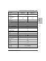
11.1 Order data
Model number
Short description
Figure
Wall mounting
8BVI0220HWS0.000-1
8BVI0440HWS0.000-1
ACOPOSmulti inverter module 22A, HV, wall-mounting
ACOPOSmulti inverter module 44A, HV, wall-mounting
Cold plate or feed-through mounting
8BVI0220HCS0.000-1
ACOPOSmulti inverter module 22A, HV, cold plate or feedthrough mounting
8BVI0440HCS0.000-1
ACOPOSmulti inverter module 44A, HV, cold plate or feedthrough mounting
8BVI0440HCS0.000-1
Table 40: Order data - 8BVI inverter modules, 16kW ... 32kW
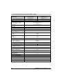
Required accessories
Model number
Short description
Comment
Page
8TB2106.2010-00
Amount
1
Screw terminal 6 pins, 1 row RM5.08
Label 1: numbered serially
Plug for X1 connection
---
8TB2108.2010-00
1
Screw terminal 8 pins, 1 row RM5.08
Label 1: numbered serially
Plug for X2 connection
---
8TB2104.203L-00
1
Screw terminal 4 pins, 1 row RM5.08
Label 3: T- T+ B- B+
Coding L: 1010
Plug for X4A connection
---
8TB4104.204G-00 1)
1
Screw terminal 4 pins, 1 row RM10.16
Label 4: PE W V U
Coding G: 0110
Plug for X5A connection
---
8TB4104.204G-10 2)
1
Screw terminal 4 pins, 1 row RM10.16
Label 4: PE W V U
Coding G: 0110
Plug for X5A connection
---
Table 41: Required accessory for 8BVI inverter modules, 16kW ... 32kW
1) Only for 8BVI0220HxS0.000-1.
2) Only for 8BVI0440HxS0.000-1.
80
ACOPOSmulti User's Manual V 0.39
Technical data • 8BVI inverter modules 16kW ... 32kW
Model number
Short description
Comment
Page
8BAC0120.000-1
max. 2
ACOPOSmulti plug-in module,
EnDat 2.1 interface
---
99
8BAC0120.001-1
max. 2
ACOPOSmulti plug-in module,
EnDat 2.2 interface
---
---
8BAC0122.000-1
max. 2
ACOPOSmulti plug-in module,
Resolver interface
---
107
8BAC0124.000-1
max. 2
ACOPOSmulti plug-in module,
SinCos interface
---
127
1
Shield component set consisting of:
1 shield plate 1x type 0
1 hose clamp, W 9mm, D 12-22mm
Shield component set for motor cables with
a cable diameter of 12 - 22 mm
---
8SCS005.0000-00
Up to 2
Shield component set consisting of:
1 slot cover shield sheet
Shield sheet for covering free plug-in
module slots
---
8SCS002.0000-00
1
Shield component set consisting of:
1 clamping plate
2 clamps D 4-13.5mm
2 screws
Shield component set for I/O cable with a
cable diameter of 4 - 13.5 mm
---
8SCS007.0000-00 2)
1
Shield component set consisting of:
1 shield mounting plate, 2x, 45°
4 screws
Base plate for mounting shield component
set 8SCS008.0000-00
---
8SCS008.0000-00 2)
1
Shield component set consisting of:
1 shield plate, 2x, type 0
1 hose clamp, W 9mm, D 23-35mm
Shield component set for motor cables with
a cable diameter of 23 - 35 mm
---
8BXF001.0000-00
---
ACOPOSmulti fan module
Replacement fan for ACOPOSmulti modules
(8BVP/8B0C/8BVI/8BVE/8B0K)
Replacement fan for ACOPOSmulti
modules (8BVP/8B0C/8BVI/8BVE/8B0K)
---
8SCS000.0000-00 1)
Amount
Chapter 2
Technical data
Optional accessories
Table 42: Optional accessory for 8BVI inverter modules, 16kW ... 32kW
1) Only for 8BVI0220HxS0.000-1.
2) Only for 8BVI0440HxS0.000-1.
11.2 Technical data
Product ID
Wall mounting
Cold plate or feed-through mounting
8BVI0220HWS0.000-1
8BVI0220HCS0.000-1
8BVI0440HWS0.000-1
8BVI0440HCS0.000-1
General information
C-UL-US listed
Yes
Available cooling and mounting methods
Wall mounting
Cold plate or feed-through mounting
Yes
Yes
Module width
2
Table 43: Technical data for inverter modules 16kW ... 32kW
ACOPOSmulti User's Manual V 0.39
81
Technical data • 8BVI inverter modules 16kW ... 32kW
Product ID
Wall mounting
Cold plate or feed-through mounting
8BVI0220HWS0.000-1
8BVI0220HCS0.000-1
8BVI0440HWS0.000-1
8BVI0440HCS0.000-1
DC bus
Voltage
Max.
800 VDC
900 VDC
Continuous power consumption
In preparation
Power loss at max. device power
DC bus capacitance
In preparation
495 µF
Design
990 µF
ACOPOSmulti backplane
24 VDC supply
Input voltage
25 VDC ±1.6%
Input capacitance
32.9 µF
20 W + P24 V Out {0 ... 10 W} 1) + PHoldingBrake + 2 * PFan8B0M... 2)
Max. power consumption
Design
ACOPOSmulti backplane
Motor connector
Continuous power 3)
Continuous current
3)
Reduction of continuous current depending on
switching frequency and cooling method 4)
Switching frequency 20 kHz
Wall mounting5)
Installing the cold plate6)
Feed-through mounting
Switching frequency 10 kHz
Wall mounting5)
Installing the cold plate6)
Feed-through mounting
Switching frequency 5 kHz
Wall mounting5)
Installing the cold plate6)
Feed-through mounting
Reduction of continuous power depending on
altitude
Starting at 500 m above sea level
Peak current
Rated switching frequency
Possible switching frequencies9)
Max. rate of rise in voltage according to
IEC EN 60034-17 10)
16 kW
32 kW
22 Aeff
44 Aeff
0.31 A/K (from -16°C) 7)
0.36 A/K (from 5°C) 8)
In preparation
0.36 A/K (from -77°C) 7)
0.32 A/K (from -82°C) 8)
In preparation
0.4 A/K (from 31°C)
0.5 A/K (from 49°C)
In preparation
0.5 A/K (from -10°C) 7)
0.62 A/K (from 6°C) 8)
In preparation
No reduction
No reduction
In preparation
1.57 A/K (from 40°C)
0.8 A/K (from 45°C)
In preparation
2.2 Aeff per 1000 m
4.4 Aeff per 1000 m
55 Aeff
88 Aeff
5 kHz
5/10/20 kHz
10 kV/µs
Protective measures
Overload protection
Short circuit and ground fault
Yes
Yes
Maximum motor line length depending on the
switching frequency 11)
Switching frequency 5 kHz
Switching frequency 10 kHz
Switching frequency 20 kHz
25 m
25 m
25 m
Table 43: Technical data for inverter modules 16kW ... 32kW (Forts.)
82
ACOPOSmulti User's Manual V 0.39
Technical data • 8BVI inverter modules 16kW ... 32kW
Product ID
Wall mounting
Cold plate or feed-through mounting
8BVI0220HWS0.000-1
8BVI0220HCS0.000-1
Design
U, V, W, PE
Shield connection
8BVI0440HWS0.000-1
8BVI0440HCS0.000-1
Terminal connection cross sections
Flexible and fine wire lines
with wire tip sleeves
Approbation data
UL/C-UL-US
CSA
Terminal cable outer-cross-section dimension of
the shield connection
0.5 - 6 mm²
0.5 - 16 mm²
20 - 8
20 - 8
20 - 6
20 - 6
12 - 22 mm
23 - 35 mm
Chapter 2
Technical data
Connectors
Yes
Motor holding brake connection
Output voltage
24 VDC +5.8% / -0.1%
Continuous current
4.2 A
0.15 Ω
Max. internal resistance
Extinction potential
Approx. 30 V
Max. extinction energy per connection
3 Ws
Max. switching frequency
0.5 Hz
Protective measures
Overload and short-circuit protection
Cable breakage monitoring
Undervoltage monitoring
Max. over-current limitation
Response threshold for cable breakage
monitoring
Response threshold for undervoltage
monitoring
Yes
Yes
Yes
10 A
Approx. 0.5 A
24 VDC +0% / -5%
Trigger inputs
Number of inputs
2
Wiring
Sink
Electrical isolation
Input - inverter module
Input - Input
Yes
No
Input voltage
Rated
Maximum
24 VDC
30 VDC
Switching threshold
LOW
HIGH
<5 V
>15 V
Input current at rated voltage
Switching delay
Positive edge
Negative edge
Approx. 10 mA
52 µs ± 0.5 µs (digitally filtered)
53 µs ± 0.5 µs (digitally filtered)
Modulation compared to ground potential
Max. ±38 V
Table 43: Technical data for inverter modules 16kW ... 32kW (Forts.)
ACOPOSmulti User's Manual V 0.39
83
Technical data • 8BVI inverter modules 16kW ... 32kW
Product ID
Wall mounting
Cold plate or feed-through mounting
8BVI0220HWS0.000-1
8BVI0220HCS0.000-1
8BVI0440HWS0.000-1
8BVI0440HCS0.000-1
24 V Out
Amount
2
Output voltage
DC bus voltage 260 ... 315 VDC
DC bus voltage 315 ... 900 VDC
Fuse protection
25 VDC * (DC bus voltage / 315)
24 VDC ±6%
500 mA (slow-blow) electronic,
automatic reset
Enable inputs
Number of inputs
2
Wiring
Sink
Electrical isolation
Input - inverter module
Yes
Input voltage
Rated
Maximum
24 VDC
30 VDC
Switching threshold
LOW
HIGH
<5 V
>15 V
Input current at rated voltage
Approx. 30 mA
Switching delay @ 24 VDC
Enable 1 -> 0, PWM off
Enable 0 -> 1, Ready for PWM
Max. 20,5 ms
Max. 100 µs
Modulation compared to ground potential
Max. ±38 V
Operational conditions
Ambient temperature during operation
Max. ambient temperature 12)
Relative humidity during operation
Installation at altitudes above sea level
Maximum installation altitude 13)
Degree of pollution according to EN 60664-1
Overvoltage cat. according to
IEC 60364-4-443:1999
EN 60529 protection
5 to 40°C
+55°C
5 to 85%, non-condensing
0 to 500 m
4000 m
2 (non-conductive material)
III
IP20
Storage and transport conditions
Storage temperature
-25 to +55°C
Relative humidity during storage
5 to 95%, non-condensing
Transport temperature
-25 to +70°C
Relative humidity during transport
95% at +40°C
Table 43: Technical data for inverter modules 16kW ... 32kW (Forts.)
84
ACOPOSmulti User's Manual V 0.39
Technical data • 8BVI inverter modules 16kW ... 32kW
Product ID
Wall mounting
Cold plate or feed-through mounting
8BVI0220HWS0.000-1
8BVI0220HCS0.000-1
8BVI0440HWS0.000-1
8BVI0440HCS0.000-1
Mechanical characteristics
Weight
Wall mounting
Cold-plate
Feed-through mounting
106.5 mm
317 mm
263 mm
212 mm
209 mm
Chapter 2
Technical data
Dimensions14)
Width
Height
Depth
Wall mounting
Cold-plate
Feed-through mounting
Approx. 5.2 kg
Approx. 4.2 kg
Approx. 4.2 kg
Table 43: Technical data for inverter modules 16kW ... 32kW (Forts.)
1) The power consumption P24 V Out corresponds to the power that is output on the module's X2 / +24 V Out 1 and X2 / +24 V Out 2
connections (max. 10 W).
2) The power consumption PFan8B0M... corresponds to the portion of the power that is used by the fan modules in the mounting plate / by
the 8B0M0040HFF0.000-1 fan module and can be found in the technical data for the respective 8B0M... mounting plate.
3) The continuous power and continuous current are valid for the following boundary conditions: Nominal DC bus voltage 800 VDC,
nominal switching frequency 5 kHz, 40°C ambient temperature, installation altitudes < 500 m above sea level.
4) Valid in the following conditions: Nominal DC bus voltage 800 VDC, minimum permissible coolant flow volume (3 l/min). The nominal
switching frequency values for the respective ACOPOSmulti inverter module are marked in bold.
5) The temperature specifications are based on the ambient temperature.
6) The temperature specifications are based on the return temperature of the cold plate mounting plate.
7) The module cannot supply the full continuous current at this switching frequency. This unusual value for the ambient temperature, at
which a derating of the continuous current must be accounted for, ensures that the derating of the continuous current can be
determined in the same manner as at other switching frequencies.
8) The module cannot supply the full continuous current at this switching frequency. This unusual value for the return temperature, at
which a derating of the continuous current must be accounted for, ensures that the derating of the continuous current can be
determined in the same manner as at other switching frequencies.
Caution! Condensation can occur at low flow-temperatures and low return-temperatures. The designs in the
section "Condensation", auf Seite 203 must be taken into consideration!
9) B&R recommends operating the module at nominal switching frequency. Operating the module at a higher switching frequency for
application-specific reasons reduces the continuous current and increases the CPU load.
When using double-axis modules, the increased CPU load causes a reduction of the functional range in the drive; if this is not taken
into consideration then it can cause the computing time to be exceeded in extreme cases.
10) The value listed is only valid for motor cables with a length > 3 m and also depends (to a small extend) on the motor used.
11) Information:
When using two motor cables that are connected in parallel, the maximum permissible motor cable lengths are reduced by
half.
The total length of all motor cables per backplane module is limited (see section 3 "Line filter 8BVF" on page 41).
12) Continuous operation of ACOPOSmulti inverter modules at ambient temperatures ranging from 40°C to max. 55°C is possible (taking
the continuous current reductions listed into consideration), but results in a shorter lifespan.
13) Continuous operation of ACOPOSmulti inverter modules at altitudes ranging from 500 m to 4000 m above sea level is possible (taking
the continuous current reductions listed into consideration). Additional requirements are to be arranged with B&R.
14) The dimensions define the true device dimensions including the respective mounting plate. Make sure to leave additional space above
and below the device for mounting, connections and air circulation (see section 2 "Dimension diagrams and installation dimensions"
on page 143).
ACOPOSmulti User's Manual V 0.39
85
Installation • Dimension diagrams and installation dimensions • Wall mounting
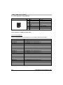
2.4.7 Inverter modules 8BVI0220HWS0.000-1, 8BVI0440HWS0.000-1
8B0MnnnnHW00.000-1
n ... Number of width units of the mounting plate
... For proper air circulation, at least 60 mm has to be left free above and below the module.
To ensure that the fan modules in the mounting plate can be exchanged easily, at least 250 mm has to be left free below the
module.
... nnnn indicates the number of slots (0160 equals 16 slots)
Figure 29: Dimensional diagram and installation dimensions for 8BVI0220HCW0.000-1,
8BVI0440HWS0.000-1
156
ACOPOSmulti User's Manual V 0.39
Wiring • 8BVI inverter modules
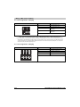
6.3 8BVI0220HxS0.000-1, 8BVI0440HxS0.000-1
Figure 110: Overview of pin assignments - 8BVI0220HxS0.000-1, 8BVI0440HxS0.000-1
310
ACOPOSmulti User's Manual V 0.39
Wiring • 8BVI inverter modules
6.3.1 Pin assignments - X1 plug
X1
Pin
Name
Function
1
Enable 1
Axis 1: Enable 1
2
COM (1)
Axis 1: Enable 1 0 V
3
Enable 2
Axis 1: Enable 2
4
COM (3)
Axis 1: Enable 2 0 V
5
S1/B+ 1)
Axis 1: Brake + / Activation for the external
holding brake
6
S2/B- 1)
Axis 1: Brake - / Activation for the external
holding brake
Table 144: Pin assignments for X1 plug - 8BVI0220HxS0.000-1, 8BVI0440HxS0.000-1
1) If the holding brake is connected via an additional external relay contact (ground-in e.g. via the conections S1/S2) instead of via the
internal transistor, then the internal quenching circuit has no effect! In this case, the customer must make sure that neither the relay
contact nor the braking coil are damaged when switching off the brake. This can be done by interconnecting the coil or - better still interconnecting the contact with a quenching circuit.
X2
Pin
Name
Function
1
Trigger1
Trigger 1
2
COM (1)
Trigger 1 0 V
3
COM (4)
+24 V output 1 0 V
4
+24 V Out 1
+24 V output 1
5
Trigger2
Trigger 2
6
COM (5)
Trigger 2 0 V
7
COM (8)
+24 V output 2 0 V
8
+24 V Out 2
+24 V output 2
Chapter 5
Wiring
6.3.2 Pin assignments - X2 plug
Table 145: Pin assignments for X2 plug - 8BVI0220HxS0.000-1, 8BVI0440HxS0.000-1
ACOPOSmulti User's Manual V 0.39
311
Wiring • 8BVI inverter modules
6.3.3 Pin assignments - X3A, X3B plugs
X3A, X3B
1
Pin
Name
Function
1
RXD
Receive signal
2
RXD\
Receive signal inverted
3
TXD
Transmit signal
4
Shield
Shield
5
Shield
Shield
6
TXD\
Transmit signal inverted
7
Shield
Shield
8
Shield
Shield
Table 146: Pin assignments for X3A, X3B plugs - 8BVI0220HxS0.000-1, 8BVI0440HxS0.000-1
Usage guidelines for B&R Powerlink cables
Special usage guidelines
Special usage guidelines must be adhered to for the following B&R Powerlink cables:
The
mechanism forShort
thisdescription
B&R Powerlink cable is protected by a soft plastic clip
Modelunlocking
number
X20CA0E61.0002
Ethernet POWERLINK connection cables, RJ45 to RJ45, 0.2 m
X20CA0E61.0005
Ethernet POWERLINK connection cables, RJ45 to RJ45, 0.5 m
X20CA0E61.0010
Ethernet POWERLINK connection cables, RJ45 to RJ45, 1.0 m
X20CA0E61.0020
Ethernet POWERLINK connection cables, RJ45 to RJ45, 2.0 m
X20CA0E61.0030
Ethernet POWERLINK connection cables, RJ45 to RJ45, 3.0 m
X20CA0E61.0040
Ethernet POWERLINK connection cables, RJ45 to RJ45, 4.0 m
X20CA0E61.0050
Ethernet POWERLINK connection cables, RJ45 to RJ45, 5.0 m
X20CA0E61.0080
Ethernet POWERLINK connection cables, RJ45 to RJ45, 8.0 m
X20CA0E61.0100
Ethernet POWERLINK connection cables, RJ45 to RJ45, 10.0 m
X20CA0E61.0150
Ethernet POWERLINK connection cables, RJ45 to RJ45, 15.0 m
X20CA0E61.0300
Ethernet POWERLINK connection cables, RJ45 to RJ45, 30.0 m
X20CA0E61.0500
Ethernet POWERLINK connection cables, RJ45 to RJ45, 50.0 m
X20CA3E61.0100
Ethernet POWERLINK connection cables, RJ45 to RJ45, can be used in cable drag chains, 10.0 m
X20CA3E61.0150
Ethernet POWERLINK connection cables, RJ45 to RJ45, can be used in cable drag chains, 15.0 m
X67CA0E41.0010
Ethernet POWERLINK attachment cables, RJ45 to M12, 1.0 m
X67CA0E41.0050
Ethernet POWERLINK attachment cables, RJ45 to M12, 5.0 m
X67CA0E41.0150
Ethernet POWERLINK attachment cables, RJ45 to M12, 15.0 m
X67CA0E41.0500
Ethernet POWERLINK attachment cables, RJ45 to M12, 50.0 m
X67CA3E41.0150
Ethernet POWERLINK attachment cables, RJ45 to M12, can be used in cable drag chains, 15.0 m
Table 147: Overview of B&R Powerlink cables
312
ACOPOSmulti User's Manual V 0.39
Wiring • 8BVI inverter modules
The unlocking mechanism for this B&R Powerlink cable is protected by a soft plastic clip (see
figure 111 "B&R Powerlink cable").
Soft plastic clip
Unlocking mechanism
Figure 111: B&R Powerlink cable
This soft plastic clip connects the unlocking mechanism to the connector housing when extended
and is designed to prevent the unlocking mechanism from breaking off when disconnecting the
cable.
Disconnecting the B&R Powerlink cable from ACOPOSmulti modules
The RJ45 plug must be unlocked by pressing on the front part of the soft plastic clip and the B&R
Powerlink cable must then be disconnected from the ACOPOSmulti module (see figure 112
"Correct unlocking of B&R Powerlink cables") .
Press here to unlock the B&R Powerlink cable
Soft plastic clip
Unlocking mechanism
Chapter 5
Wiring
Figure 112: Correct unlocking of B&R Powerlink cables
Caution!
Before disconnecting the B&R Powerlink cable from ACOPOSmulti modules, make
sure that the RJ45 plug is completely unlocked.
ACOPOSmulti User's Manual V 0.39
313
Wiring • 8BVI inverter modules
6.3.4 Pin assignments - X4A plug
X4A
B+
B-
T+
Name
Function
T-
Axis 1: Temperature sensor -
T+
Axis 1: Temperature sensor +
B-/S2 1)
Axis 1: Brake - / Activation for the external
holding brake
B+/S1 1)
Axis 1: Brake + / Activation for the external
holding brake
T-
Table 148: Pin assignments for X4A plug - 8BVI0220HxS0.000-1, 8BVI0440HxS0.000-1
1) If the holding brake is connected via an additional external relay contact (ground-in e.g. via the conections S1/S2) instead of via the
internal transistor, then the internal quenching circuit has no effect! In this case, the customer must make sure that neither the relay
contact nor the braking coil are damaged when switching off the brake. This can be done by interconnecting the coil or - better still interconnecting the contact with a quenching circuit.
6.3.5 Pin assignments - X5A plug
X5A
Name
Function
PU
Axis 1: Protective ground conductor
W
Axis 1: Motor connection W
V
Axis 1: Motor connection V
U
Axis 1: Motor connection U
Table 149: Pin assignments for X5A plug - 8BVI0220HxS0.000-1, 8BVI0440HxS0.000-1
314
ACOPOSmulti User's Manual V 0.39
Wiring • 8BVI inverter modules
Chapter 5
Wiring
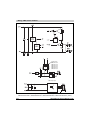
6.3.6 Input/output circuit diagram
Figure 113: Input/output circuit diagram
8BVI0014HxS0.000-1, 8BVI0028HxS0.000-1, 8BVI0055HxS0.000-1, 8BVI0110HxS0.000-1
ACOPOSmulti User's Manual V 0.39
315
Wiring • 8BVI inverter modules
Plug-in module
8BAC0120.00x-1
8BAC0121.000-1
8BAC0122.000-1
8BAC0123.00x-1
8BAC0124.000-1
8BAC0132.000-1
IGBT output stage
Figure 113: Input/output circuit diagram
8BVI0014HxS0.000-1, 8BVI0028HxS0.000-1, 8BVI0055HxS0.000-1, 8BVI0110HxS0.000-1 (Forts.)
316
ACOPOSmulti User's Manual V 0.39