1
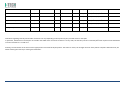
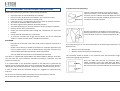
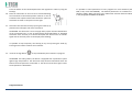
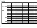
MNPG118
Rev.0 - 03-08-2013
USER MANUAL
SYMBOLS ............................................................................................................ 30
SUMMARY
EM COMPATIBILITY – EMC TABLES ...................................................................... 30
SUMMARY ........................................................................................................... 2
WARRANTY ........................................................................................................ 32
USER MANUAL ..................................................................................................... 3
SAFETY INFORMATION.......................................................................................... 3
USE ...................................................................................................................... 5
CONDITIONS OF USE and EQUIPMENT ................................................................... 7
DEVICE DESCRIPTION ............................................................................................ 8
INSTALLATION .....................................................................................................11
ULTRASOUND TREATMENT .................................................................................. 11
PRELIMINARY ELECTROTHERAPY INSTRUCTIONS ..................................................17
ELECTROTHERAPY TREATMENT ............................................................................18
COMBINED TREATMENT ULTRASOUND/ELECTROTHERAPY ...................................25
CLEANING, MAINTENANCE AND STORAGE ............................................................26
OPERATION TROUBLES ........................................................................................27
ENVIRONMENT PROTECTION ............................................................................... 27
TECHNICAL FEATURES ..........................................................................................28
This manual reflects the current state of machine technology and shall not be
considered obsolete solely because updated at a later date on the basis of acquired
experience.
USER MANUAL
This manual is addressed to:
- machine user;
The manufacturer reserves the right to update the production and the manuals with
no obligation to update previous versions.
- owner;
The manufacturer declines all responsibility for:
- managers;
- improper use of the machine;
- handling personnel;
- use contrary to specific national laws;
- installers;
- incorrect installation;
- users;
- defective power supply;
- maintenance personnel.
- improper maintenance;
It contains general information on the operation, precautionary practices, and
maintenance information of the device I-TECH UE.
- unauthorised modifications and interventions;
This is an essential reference guide for users. It is essential to read the manual
carefully before installing and using the device and to keep it at hand for quick
reference.
Partial or complete non-observance of the recommendations may lead to
malfunction and damage of the device, and therefore the warranty will no longer be
valid.
Following the provisions and the recommendations supplied by the manufacturer
scrupulously is the only way of achieving the best results and to benefit from a quick
and efficient technical assistance if needed.
The limits of this manual:
- the user manual cannot replace actual user experience;
- for particularly demanding operations, this instruction manual only represents a
remainder of the main operations.
This user manual must be considered an integral part of the equipment and must be
preserved for future reference until the device is dismantled. The instruction manual
must be available for reference at the place of use of the device and preserved
carefully.
- use of material or spare parts that are not specific for the model;
- partial or complete non-observance of the instructions supplied;
- exceptional events.
To get further information, consult the fabricant.
SAFETY INFORMATION
Cautions
- Read carefully the contraindications.
- Respect the limitations and hazards associated with the use of the device. Pay attention to
the labels and symbols placed on the unit. Always follow your prescribing
doctor's or therapist's recommendations.
- Do not operate this unit in an environment where other devices are used that
intentionally radiates electromagnetic energy in an unshielded manner.
- Do not use sharp objects such as pencil point or ballpoint pen to operate the buttons on
the control panel.
- Before each use inspect applicators and cables integrity.
- The device should not be placed next to or on top of other devices. Should it prove
necessary to place it next to or on top of other devices, supervision is essential at all times
to control its normal functioning.
- Precautions must be taken regarding the electromagnetic compatibility of the device,
which must be installed and commissioned in compliance with the EMC provided in this
manual.
I.A.C.E.R. Srl
3
-
-
Portable RF devices can affect the functioning of the device. Do not use mobile phones or
other devices that emit electromagnetic fields nearby. This may result in incorrect
operation of the unit.
Only use the device for the recommended applications.
Do not use the device in presence of inflammable anesthetic mixture and in environments
with high concentrations of oxygen. I.A.C.E.R. will not be held responsible for any accident
if the above instructions are not complied with in full.
Warnings
-
-
-
Make sure of the device connection to an electrical system in conformity with the current
National laws.
Care must be taken when operating this equipment around other equipment. Potential
electromagnetic or other interference could occur to this or to the other equipment. Try
to minimize this interference by not using other equipment in conjunction with I-TECH UE.
Before administering any treatment to a patient you should become acquainted with the
operating procedures for each mode of treatment available, as well as the indications,
contraindications, warnings and precautions. Consult other resources for additional
information regarding the application of Ultrasound.
To avoid the risk of electric shock disconnect the device from the electrical system before
maintenance service.
Use of accessories, transducers and cables other than those specified here (even as
internal spare parts) may result in EM immunity reduction or in EM emissions increase.
The device must not be used in the same environment where magnetic resonance devices
are working or are installed.
Contraindications
- Ultrasound therapy must not be performed near the uterus on pregnant women or those
who suspect they might be pregnant. Therefore the ultrasound beam should not be used
in this area without ensuring that the patient is not pregnant.
- This device should not be used over the thoracic area if the patient is using a cardiac
pacemaker in order to avoid interferences between the ultrasound device and the
pacemaker.
Do not direct the beam towards or near the eyes.
- This device should not be used over cardiac area.
- This device should not be used over neoplastic lesions.
- Do not use near testicles not to increase their temperature.
- The treatment with ultrasounds should be avoided in those areas affected by
thrombophlebitis not to make the thrombus move. Avoid treating patients with deep vein
thrombosis, embolism or arteriosclerosis..
- Tissues that have previously been treated with X rays or other radiations should not be
treated with ultrasounds.
- Using ultrasounds on the stellate ganglion, on the spinal column after a laminectomy, on
the area surrounding the main nerves or the cranium should be avoided.
- .
-
-
This device should not be used on ischemic tissues in individuals with vascular disease
where the blood supply would be unable to follow the increase in metabolic demand and
tissue necrosis might result.
This device should not be used over a healing fracture.
Avoid using ultrasounds near bone growth centres in kids/growing children.
Electrotherapy contraindications
- Do not use this device on patients who have a cardiac pacemaker, implanted defibrillator,
or other implanted metallic or electronic device, because this may cause electric shock,
burns, electrical interference, or death.
- Do not use this device on patients whose pain syndromes are undiagnosed.
Warnings for electrotherapy
- Do not apply stimulation over the patient's neck because this could cause severe muscle
spasms resulting in closure of the airway, difficulty in breathing, or adverse effects on
heart rhythm or blood pressure;
- Do not apply stimulation across the patient's chest, because the introduction of electrical
current into the chest may cause rhythm disturbances to the patient's heart;
- Do not apply stimulation over open wounds or inflamed areas or skin eruptions (e.g.,
phlebitis, thrombophlebitis, varicose veins);
- Do not apply stimulation over, or in proximity to, cancerous lesions;
- Do not apply stimulation in presence of electronic monitoring equipment (e.g., cardiac
monitors, ECG alarms), which may not operate properly when the electrical stimulation
device is in use;
- Do not use the device in wet environment, in bath or during shower.
- Do not use the device when the patient is sleeping.
- Do not apply stimulation while the patient is driving, operating machinery, or during any
activity in which electrical stimulation can put the patient at risk of injury.
- Consult with the doctor before using the device, because the device may cause heart
rhythm disturbances in susceptible individuals;
- Apply stimulation only to intact, clean, healthy skin.
- This device should not be used for symptomatic local pain relief unless etiology is
established or unless a pain syndrome has been diagnosed. Patients with arterial or
venous thrombosis or thrombophlebitis are at risk of developing embolisms when
electrical stimulation is applied over or adjacent to the vessels containing the thrombus. If
a patient has a history of deep vein thrombosis, even many years past, the affected area
should not be stimulated.
- Recent fractures should not be treated in order to avoid unwanted motion.
- Stimulation should not be applied immediately after a trauma or to tissues susceptible to
hemorrhage.
- Do not apply electrodes directly over the eyes or inside body cavities.
- Do not use electrical stimulation with high frequency surgical equipment or microwave or
shortwave therapy systems.
- Keep electrodes separated during treatment. Electrodes in contact with each other could
result in improper stimulation or skin burns.
I.A.C.E.R. Srl
4
-
Since the effects of stimulation of the brain are unknown, stimulation should not be
applied across the head, and electrodes should not be placed on opposite sides of the
head.
-
Precautions
-
-
-
-
-
Ultrasounds should not be used on areas with reduced sensitivity or circulation. Patients
experiencing reduced sensitivity may not be able to warn their therapist/doctor when the
ultrasound is too intense. Patients experiencing circulation problems may suffer from an
excessive increase of temperature in the treated area.
If the patient feels a deep and sharp pain during the treatment, the intensity must be
reduced to a comfortable level.
The tendency to bleed is increased by the heat as more blood flows in the area. Be careful
when treating patients with bleeding disorders.
We advise moving the head if the intensity is more than 0,5 W/ sq cm.
Avoid heating or overheating the capsule in cases of acute and subacute arthritis.
This device should not be used for symptomatic local pain relief unless etiology is
established or unless a pain syndrome has been diagnosed.
This device should not be used when cancerous lesions are present in the treatment area.
Cautions should be used for patients affected by the following diseases: areas of the spinal
column which underwent a laminectomy, anesthesised areas, patients with bleeding
disorders.
Ultrasound should be routinely checked before each use to determine that all controls
function normally, especially that the intensity control does properly adjust the intensity
of the ultrasonic power output in stable manner. Also, determine that the treatment time
control does actually terminate ultrasonic power output when the timer reaches zero.
Handle the handpiece with care to preserve its characteristics.
Before using the device pay attention to the appllicators and head integrity in order to
avoid the ingress of liquids.
The ultrasound therapy controls unit is not designed to prevent the ingress of water or
liquids. Ingress of water of liquids could cause malfunction of internal components of
system and therefore create risk of injury to the patient/user.
.
Precaution for electrotherapy use
- The long-term effects of chronic electrical stimulation are unknown.
- Electrical stimulation is not a substitute for pain medications and other pain management
therapies.
- The safety of electrical stimulation during pregnancy has not been established.
- Some patients may experience skin irritation or hypersensitivity due to the electrical
stimulation or electrical conductive medium (gel);
- Patients with suspected or diagnosed heart disease should follow precautions
recommended by their doctors;
- Patients with suspected or diagnosed epilepsy should follow precautions recommended
by their doctors.
-
Use caution when the patient has a tendency to bleed internally, such as following an
injury or fracture.
Use caution following recent surgical procedures as stimulation may affect the patient's
healing process;
Use caution if stimulation is applied over the menstruating or pregnant uterus;
Use caution if stimulation is applied over areas of skin that lack normal sensation.
Use this device only under the continued supervision of a licensed doctor/therapist.
Electrical stimulation is ineffective for treatment pain of central nervous system.
Use extreme caution when treating patients who may not be able to report discomfort or
pain.
Patients should not be left unattended during any treatment.
Keep this device out of the reach of children.
Unwanted effects
- Skin irritation, inflammation, and burns are potential adverse reactions.
- Patients may experience headache and other painful sensations during or following the
application of electrical stimulation near the eyes, head and face. and to the head and
face;
- In case of undesired effects, suspend the therapy, stop using the device straight away and
contact your doctor.
- Follow the instructions in order to minimise the undesired effects of the ultrasound
therapy.
- If the handpiece moves too slowly the patient may experience sharp and/or deep
peripheral pain. If it moves too quickly, or if the handpiece is not held correctly, the
therapeutic effects of the ultrasound might be reduced.
- Some patients might be particularly sensitive to ultrasound and might therefore
experience undesired reactions such as hot flushes in the treated area. Check the treated
area before, during and after the treatment and suspend it in case of undesired effects.
- Make sure that the handpiece is in contact with the skin using a specific ultrasound gel.
Any substance used for this purpose must be highly conductive. Air is a terrible conductor
of ultrasound waves.
USE
I-TECH UE is a device for ultrasound therapy.
Ultrasound treatment is indicated for several chronic and sub-chronic treatments as:
I.A.C.E.R. Srl
•
•
•
•
•
Muscle pains and contractures
Contractures
Capsulitis
Bursitis
Myositis
5
•
•
•
Soft tissues diseases
Tendinitis
Tendinosis
Electrotherapy (TENS, interferential waves, premodulated, EMS and Kotz “Russian”)
is particularly indicated for the treatment of chronic and acute pains, for postoperated oedema and in presence of inflammations.
Electrotherapy is also indicated for rehabilitation post-trauma and for the prevention
of muscle atrophy. Moreover it is indicated for local circulation increase and for
muscle maintaining.
Use: hospital and domestic use. it is recommended the use only by seasoned
professional.
Expected lifetime (time after which we suggest sending the device to the
manufacturer for safety checks): 2 years.
I.A.C.E.R. Srl
6
CONDITIONS OF USE and EQUIPMENT
Environmental conditions for use:
-
Environment temperature: from +10° to +40°C;
-
Relative humidity: from 10% to 93% without condensation;
-
avoid direct sunlight, chemical products and vibrations.
The device is equipped with the following accessories:
1
2
3
4
5
6
7
8
9
10
11
12
13
14
Description
Silicone conductive electrode 60x90mm
Silicone conductive electrode 70x110mm
Sponge for silicone electrode 70x100mm
Sponge for silicone electrode 80x120mm
4 electrodes 50x50mm
4 electrodes 50x100mm
Elastic belt for electrodes fastening 75x1200mm
Elastic belt for electrodes fastening 75x600mm
Electrical stimulation cables with 2 derivations red/black
Power supply 15V 3A
Power supply cable
Electrotherapy cable
Single plug cable for combined electrotherapy
Ultrasound head with 5cmq area
User manual
Electrodes positions user manual
Ultrasound gel
Kit
2 pieces
2 pieces
2 pieces
2 pieces
2 pieces
2 pieces
1 piece
1 piece
2 pieces
1 piece
1 piece
1 piece
1 piece
1 piece
1 piece
1 piece
1 piece
All accessories are available on demand as spare parts. .
Moreover the multi-frequency 1/3 MHz ultrasound head with 1 cmq area is available
on demand.
I.A.C.E.R. Srl
7
DEVICE DESCRIPTION
1.
2.
3.
4.
5.
6.
7.
Channel 1 intensity selection knob
Channel 2 intensity selection knob
Programs parameters control knob and PAUSE
Parameter confirm and STOP button
Led indicator
LCD display
Parameters selection buttons:
B1:
mode
selection
(ultrasound,
electrotherapy, combined) and waveform
selection
B2: program selection
B3: Burst/vector/frequency modulation
selection
B4: frequency/carrier frequency selection
B5: Duty cycle/high frequency/width
modulation selection
B6: low frequency/impulse duration
selection
B7: therapy time/contraction-recovery
cycle/ramp up selection
B8: frequency/ultrasound duty cycle
selection
8. Ultrasound Intensity selection knob
9. Power supply socket
10. ON/OFF button
11. Handle socket
12. Electrostimulation cable socket
I.A.C.E.R. Srl
8
LABELS
LEGEND
•
•
•
•
•
•
•
•
•
•
•
•
•
•
•
•
CC – Constant current output mode
CV – Constant voltage output mode
F.M. – Frequency modulation
Burst – Burst frequency
Freq. – Frequency
C.F. – Carrier frequency
Duty – Duty cycle for Russian waveform (Kotz) for B5 button
Beat H. – High beat frequency selection
A.M. – Amplitude modulation
Beat L. – Low beat frequency selection
P.Dur. – Impulse duration
Treat. – Therapy time
Cycle – Contraction-recovery cycle
Ramp – Ramp time
Duty – Duty cycle for ultrasound for B8 button
Freq. – Ultrasound frequency
I-TECH UE
INTERFACCIA
ON /OFF button
Polarity of Power Supply
Stop treatment
Start/Pause button
Protected against the effects of immersion: for ultrasound
handle
I.A.C.E.R. Srl
9
Symbols and definitions
WEE Regulations
Applied part type BF
Product in compliance with Directive 93/42/EEC (MDD)
Attention. Current can be higher than 10 mA r.m.s or 10 V
r.m.s. over 5 seconds period
Fabricant name and address
Symbols and definitions
Interferential waveform with
4 poles
Interferential waveform with 2
poles
Russian waveform (Kotz)
TENS/EMS waveforms
Electrotherapy channels
indicators
electrotherapy/ultr
asound/combined
therapy symbols
Program
Ultrasound indicator
Constant current
Constant voltage
Parameter
Timer
Manufacturing date (month/year)
Attention. Consult operating instructions
LOT
Ultrasound handle lot
SN
Serial number of ultrasound handle
I.A.C.E.R. Srl
10
INSTALLATION
7. Press B7 button to regulate therapy time: it’s possible to adjust therapy time
from 1 to 30 minutes (stepping 1 minute) by using the knob (3).
Remove the device and all accessories from shipping cartons. Check the device
equipment.
8. Put a good quantity of conductive gel on the area to be treated or on
ultrasound head. It is recommended to use a CE conductive gel CE.
Follow the instructions below for a correct installation:
•
•
•
9. Regulate the treatment intensity using the knob (8). Press the knob to adjust
unit of measurement W (Watt) or W/cm² (Watt/cmq).
Connect the power supply cable to the power supply
Connect the power supply to the device connector
Connect the power supply plug to the wall socket
Press on ON/OFF button to switch on the device.
10. Keep the head in constant contact with the skin and make sure that the part
is covered in gel so that the therapy is effective. The green LED located next
to the head on the handpiece lights up when the device is working
ULTRASOUND TREATMENT
Follow the instructions below for ultrasound treatment:
11. The device has a head/skin coupling system for
safety reasons. If the contact is not correct and
if the intensity is set above 0,5W, the LED on
the handpiece and the symbol on the display
will start flashing. The system is not available on the 1cm head because of the
reduced contact area: the device emits an ultrasound beam even if the head
is not in contact with the skin. This is not a defect but rather a technical
choice, as it would be impossible to perform therapies on small and irregular
areas like toes or fingers with such a system.
1. Connect the ultrasound handle to the socket (11) placed on back side of the
device. Connect the cable when the device is switched off.
2. Switch on the device pressing ON/OFF button placed on lateral side, next to
power supply plug.
3. Immediately after switching on, the device carries out a self-test (10 seconds
duration). At the end display shows the last percome treatment.
4. Press WAVEFORM MODE (B1) button to show
ULTRASOUND treatment.
12. It’s possible to stop temporary the therapy at any time pressing the knob (3).
Press again the knob to continue the treatment.
13. Press the orange button
progress..
icon: this icon indicates
5. Press B8 button to regulate ultrasound working frequency (1 or 3 MHz), by
using the knob (3).
to stop immediately the treatment in
ATTENTION. For patient safety, the device will stop ultrasound treatment and LED
starts flashing on the handle if the temperature is above 42°C. It will start again when
the temperature goes down to 41°C.
6. Press again B8 button to regulate the duty cycle: it’s possible to adjust the
value from 10% to 100% stepping 10 using the knob (3).
I.A.C.E.R. Srl
11
ATTENTION. Only in the ultrasound mode the handpiece can be used for immersion
treatments. The handpiece and its cable are the only parts protected against water
damage with a IPX7 grade.
Programs features and main applications.
Make reference to the following table for programs features. All parameters are
adjustable by the user.
PROG.
FREQ.
DUTY CYCLE
TIME
SUGGERITED INT.
P-01
1MHz
50%
14 min.
1.0W/cm²
P-02
1MHz
50%
20 min.
1.0W/cm²
P-03
1MHz
50%
20 min.
1.0W/cm²
P-04
1MHz
50%
30 min.
0.5W/cm²
1.0W/cm²
P-05
1MHz
50%
16 min.
1.0W/cm²
P-06
1MHz
50%
14 min.
1.0W/cm²
P-07
1MHz
50%
14 min.
1.0W/cm²
P-08
1MHz
50%
14 min.
1.0W/cm²
P-09
1MHz
50%
14 min.
1.0W/cm²
P-10
1MHz
50%
14 min.
1.0W/cm²
I.A.C.E.R. Srl
12
TREATMENT
PRG
HANDLE POSITION
FREQ
DUTY CYCLE
TIME
HEAD
SUGGESTED INTENSITY
APPLICATIONS
NUMBERS
Acne
U-01/10
Affected area
3MHz
30%
15 min
5 cmq
1,5W/cm²
Free
Muscle fatigue
U-01/10
Affected area
1MHz
70%
20 min.
5 cmq
2 W/cm²
2-3
Algodystrophy
U-01/10
Affected area
1MHz
50%
10 min.
5 cmq
1.0W/cm² - 1,5W/cm²
10-15
Anti-inflammatory
U-01/10
Affected area
1MHz
50%
15 min.
5 cmq
1.0W/cm² - 1,5W/cm²
10-15
Arthritis
U-01/10
Affected area
1MHz
50%
15 min.
5 cmq
1.0W/cm² - 1,5W/cm²
10-15
Fingers arthritis
U-01/10
Hand fingers
1MHz
40%
15 min.
1 cmq
1.5W/cm² - 2W/cm²
10-15
Arthrosis
U-01/10
Affected area
1MHz
50%
15 min.
5 cmq
1.5W/cm² - 2W/cm²
10-15
Bursitis
U-01/10
Affected area
1MHz
30%
15 min.
5 cmq
2W/cm²
10-15
Brachialgia
U-01/10
Trapezium and arm
1MHz
30%
15 min.
5 cmq
2W/cm²
10-15
Capsulitis
U-01/10
Shoulder
1MHz
30%
15 min.
5 cmq
2W/cm²
10-15
Cavitations
U-01/10
Affected area
1MHz
70%
20 min.
5 cmq
2W/cm² - 3W/cm²
20-30
T-T headache
U-01/10
Cervical area
1MHz
50%
15 min.
5 cmq
1.0W/cm² - 1,5W/cm²
10-15
T-T headache
U-01/10
Massetere
1MHz
50%
15 min.
5 cmq
1.5W/cm²
10-15
Cervicalgias
U-01/10
Cervical area
1MHz
50%
15 min.
5 cmq
1.0W/cm² - 1,5W/cm²
10-15
Whiplash
U-01/10
Cervical and dorsal +
front zone
1MHz
50%
15 min.
5 cmq
1.0W/cm² - 1,5W/cm²
10-15
Condropathy
U-01/10
Affected area
1MHz
60%
15 min.
5 cmq
1.0W/cm² - 1,5W/cm²
10-15
Muscle contractures
U-01/10
Affected area
1MHz
70%
20 min.
5 cmq
2W/cm²
4-6
I.A.C.E.R. Srl
13
Coxarthrosis
U-01/10
Hip
1MHz
60%
15 min.
5 cmq
2W/cm²
10-15
Cramps
U-01/10
Affected area
1MHz
70%
20 min.
5 cmq
2W/cm²
4-6
Cruralgy
U-01/10
Internal thigh
1MHz
40%
15 min.
5 cmq
2W/cm²
10-15
Discopathy
U-01/10
Affected area
1MHz
50%
15 min.
5 cmq
1.0W/cm² - 1,5W/cm²
10-15
Strains
U-01/10
Affected area
1MHz
50%
15 min.
5 cmq
1.0W/cm² - 1,5W/cm²
10-15
Articular pain
U-01/10
Affected area
1MHz
50%
15 min.
5 cmq
1.0W/cm² - 1,5W/cm²
10-15
Intercostal pain
U-01/10
Affected area
1MHz
50%
15 min.
5 cmq
1.0W/cm² - 1,5W/cm²
10-15
Menstrual pain
U-01/10
Abdomen
1MHz
50%
15 min.
5 cmq
1.0W/cm² - 1,5W/cm²
10-15
Muscle pain
U-01/10
Affected area
1MHz
50%
15 min.
5 cmq
1.0W/cm² - 1,5W/cm²
10-15
Rheumatic pain
U-01/10
Affected area
1MHz
50%
15 min.
5 cmq
1.0W/cm² - 1,5W/cm²
10-15
Dorsalgy
U-01/10
Dorsal area
1MHz
50%
15 min.
5 cmq
1.0W/cm² - 1,5W/cm²
10-15
Drainage
U-01/10
Affected area
1MHz
60%
15 min.
5 cmq
2W/cm²
30
Eczemas
U-01/10
Affected area
3 MHz
50%
15 min.
5 cmq
1.0W/cm² - 1,5W/cm²
10-15
Oedemas
U-01/10
Affected area
1MHz
30%
15 min.
5 cmq
2W/cm²
10-15
Hematomas
U-01/10
Affected area
1MHz
40%
15 min.
5 cmq
2W/cm² - 3W/cm²
10-15
Epicondylitis
U-01/10
Elbow
1MHz
40%
15 min.
5 cmq
1.0W/cm² - 1,2W/cm²
10-15
Epitrocleitis
U-01/10
Internal elbow
1MHz
40%
15 min.
5 cmq
1.0W/cm² - 1,2W/cm²
10-15
Slipped disc
U-01/10
Affected area
1MHz
50%
15 min.
5 cmq
1.0W/cm² - 1,5W/cm²
10-15
Gonarthrosis
U-01/10
Knee
1MHz
50%
15 min.
5 cmq
1.5W/cm² - 2W/cm²
10-15
I.A.C.E.R. Srl
14
Lymphoedema
U-01/10
Affected area
1MHz
30%
15 min.
5 cmq
2W/cm²
10-15
Lypolisis
U-01/10
Affected area
1MHz
60%
15 min.
5 cmq
2W/cm²
30
Lumbago
U-01/10
Lumbar area
1MHz
50%
15 min.
5 cmq
1.0W/cm² - 1,5W/cm²
10-15
Massage
U-01/10
Affected area
1MHz
70%
20 min.
5 cmq
2 W/cm²
Free
Mialgy
U-01/10
Affected area
1MHz
50%
15 min.
5 cmq
1.0W/cm² - 1,5W/cm²
10-15
Mononeuropathy
U-01/10
Pain zone
1MHz
50%
15 min.
5 cmq
1.5W/cm²
12-15
Neuralgia
U-01/10
Affected area
1MHz
50%
15 min.
5 cmq
1.0W/cm² - 1,5W/cm²
10-15
Periarthritis
U-01/10
Shoulder
1MHz
70%
15 min.
5 cmq
1.0W/cm² - 1,5W/cm²
10-15
Pubalgy
U-01/10
Internal thigh
(upper zone)
1MHz
50%
15 min.
5 cmq
1.0W/cm² - 1,5W/cm²
10-15
Radiculitis
U-01/10
Affected area
1MHz
50%
15 min.
5 cmq
1.0W/cm² - 1,5W/cm²
10-15
Muscle recovery
U-01/10
Affected area
1MHz
70%
20 min.
5 cmq
2 W/cm²
Free
Rizarthrosis
U-01/10
Thumb area
1MHz
30%
15 min.
5 cmq
1,5W/cm²
10-15
Rizopathy
U-01/10
Dorsal area
1MHz
60%
15 min.
5 cmq
1,5W/cm²
10-15
Wrinkle
U-01/10
Affected area
3MHz
30%
15 min
5 cmq
1,5W/cm²
Free
Sciatalgy
U-01/10
Affected area
1MHz
50%
15 min.
5 cmq
1.0W/cm² - 1,5W/cm²
10-15
Stretch marks
U-01/10
Affected area
3MHz
40%
15 min
5 cmq
2W/cm²
Free
Venous stasis
U-01/10
Extremities limbs
1MHz
50%
15 min.
5 cmq
2W/cm²
Free
Sprains
U-01/10
Affected area
1MHz
40%
15 min.
5 cmq
2W/cm²
4-6
Muscle sprains
U-01/10
Affected area
1MHz
40%
15 min.
5 cmq
2W/cm²
8-10
I.A.C.E.R. Srl
15
Tallonitis
U-01/10
Heel
1MHz
50%
15 min.
5 cmq
1.0W/cm² - 1,5W/cm²
10-15
Tendinitis
U-01/10
Affected tendons
1MHz
50%
15 min.
5 cmq
1.0W/cm² - 1,5W/cm²
10-15
Stiff neck
U-01/10
Cervical area
1MHz
50%
15 min.
5 cmq
1.0W/cm² - 1,5W/cm²
10-15
Carpal tunnel syndrome
U-01/10
Internal wrist
1MHz
40%
15 min.
5 cmq
1.0W/cm² - 1,5W/cm²
10-15
Vascularisation
U-01/10
Affected area
1MHz
60%
15 min.
5 cmq
1.0W/cm² - 1,5W/cm²
Free
Active principle vehiculation
U-01/10
Affected area
1MHz
60%
15 min.
5 cmq
2W/cm²
Free
Indications regarding intensity and number of sessions can vary depending on the opinion of your personal doctor or therapist.
In particular, indications on intensity do not consider the width of the area to be treated. If it is very wide, the intensity can be increased by 20% with respect to what indicated and
it can be reduced if it is a small area.
Similarly, the movement on the area must be appropriate to the heat felt by the patient. The slower it moves, the stronger the heat. If the patient complains about the heat, we
advise reducing the intensity or moving the head faster.
I.A.C.E.R. Srl
16
Pregelled electrodes positioning
PRELIMINARY ELECTROTHERAPY INSTRUCTIONS
Insert the cable with the Red (+) connector into one
adhesive electrode. Insert the cable with the Black (-)
connector into one adhesive electrode. Make sure that
the connectors are inserted completely and there are no
metal parts of the pins exposed.
Before start treatment pay attention to the following indications:
•
•
•
•
•
•
•
•
•
•
•
Insure there are no contraindications to treatment.
Insure there are no abrasions or irritations in the area to be treated.
Clean the skin with neutral soap or alcohol (70%).
If the skin is hairy, it is suggested to shave the area for an optimal treatment.
Test the heat sensibility of the treatment area.
Guarantee a good contact between electrodes and skin.
Check that electrodes are correctly placed on the skin during the treatment.
Examine the skin after the treatment.
Choose the electrodes dimensions taking into consideration the area to be
treated.
Follow electrode manufacturer’s instructions.
To avoid skin irritation due to high current density, do not use electrodes
smaller in surface area than 25cm2 self-adhesive electrode.
Remove the adhesive electrodes from the protective
backing and place on the treatment area. Insure that the
entire electrode surface is in contact with patient skin.
ATTENTION:
-
Electrodes in contact with each other could result in improper stimulation or
skin burns.
-
Output current density is related to electrode size. Improper application may
result in patient injury. In case of doubts about the proper electrode size,
consult a doctor/therapist specialized in electrostimulation.
-
As an alternative you can use silicon electrodes for electrotherapy treatments, in two
different ways:
•
•
With the use of wet sponges
With the silicon electrodes and conductive gel
Use only cables and electrodes recommended by the fabricant.
This device is supplied with 50mm×50mm and 50mm×100mm adhesive electrodes.
You can select the correct adhesive electrodes according to treatment area and
output current density.
The electrodes should be placed on the treatment area and hold down using the
elastic belt supplied with the device.
It is recommended to use electrodes supplied by the fabricant to guarantee the
highest level of contact with the area to be treated and the right current density in
relation with the prescribed treatment. Properly dispose of electrodes after the use.
Insert the cable with the Red (+) connector into one
rubber electrode. Insert the cable with the Black (-)
connector into the other rubber electrode. Make sure that
the connectors are inserted completely into the electrode.
In case of doubts about the electrodes integrity it is suggested to replace them by
new ones.
Do not start the treatment before electrodes are correctly placed on the skin.
Do not take away the electrodes during the therapy.
I.A.C.E.R. Srl
17
OPTION 1: Insert the rubber electrode into the wet
electrode sponge.
OPTION 2: Put conductive gel on the rubber electrode
surface before placing it on the skin. Note: use only CE
marked gel or supplied by the fabricant..
5.
Press WAVEFORM MODE (B1) button to show
ELECTROTHERAPY treatment.
6.
Select waveforms by using the knob (3): TENS, EMS, IF-4P (Interferential 4 poles),
IF-2P (interferential 2 poles), RUSSIAN (Kotz). The icon related to the selected
waveform starts flashing.
7.
Select the program (from P01 to P10) by pressing the PROGRAM CC/CV (B2)
button: the symbol P (or S) of the program starts flashing on the display. There
are two type of programs you can select: programs with one phase (P) or with
three phases (S). You can select the program by keeping pressed PROGRAM
CC/CV button for at least 5 seconds.
: this icon indicates
In the S programs display shows the phases total number
and the number of the phase you want to set the
parameters: press B3-B7 buttons and the knob (3) to select
programs parameters (contraction, recovery, width
impulse, frequency, etc.) for each phase (please see the
following instructions regarding each parameter). Press the
knob to confirm the value for each phase.
Use elastic belts to keep the electrodes in the right position.
ELECTROTHERAPY TREATMENT
Pay attention to the follow indications to start electrotherapy treatment:
1.
Connect the black/red cables to the sockets on the
electrotherapy cables and connect this cable to the
socket (12) on the back side of the device.
2.
Connect the electrodes to the electrotherapy cables
following the instructions of the paragraph “Preliminary Electrotherapy
Instructions”.
3.
Switch on the device pressing ON/OFF button placed laterally, next to power
supply socket.
4.
Immediately after switching on, the device carries out a self-test (around 10
seconds). At the end of the self-test display shows the last perfomed treatment.
8.
Select CONSTANT CURRENT (CC) or CONSTANTE
VOLTAGE (CV) by pressing again PROGRAM CC/CV
button. The unity of measurement changes from mA (
(milliAmpere) to V (Volts).
9.
Select the waveform features by pressing B3-B7 buttons (each waveform has
different technical features):
• B3: select frequency modulation/vector/Burst/
• B4: select frequency/carrier frequency
• B5: select duty cycle/high frequency/width modulation
• B6: select low frequency/impulse duration
• B7: select therapy time/contraction-recovery cycle / slope
I.A.C.E.R. Srl
18
Press the button of the selected parameter and regulate the value by using the
knob (3).
10. Place the electrodes on the area to be treated following
the instructions of electrodes position manual. In case of
treatment with 4 poles interferential waveform place the
electrodes as shown in the picture on the right.
It’s possible to select parameters of user programs for each waveform (TENS,
EMS, IF-4P, IF-2P and RUSSIAN). The default parameters are indicated in the
following tables. Make reference to the tables with technical features indicated
in the paragraph TECHNICAL FEATURES.
11. Select the two channels intensity by using the knobs (1-2)
placed on the left upper side of the front panel.
ATTENTION. The device has a current supply safety system and the identification
of the connected load: in case of disconnected electrodes/cables or damaged
electrodes if the intensity is set above 10mA/10V the device emits an acoustic
signal and the intensity value on the display starts flashing.
It’s possible to stop temporary the therapy at any time pressing the knob (3).
Press again the knob to continue the treatment.
12. Press the orange button
to stop immediately the treatment in progress.
ATTENTION. For safety patient, the device is equipped with a protection system
against high temperatures. The device will stop electrical stimulation when the
feature board temperature reaches 80° C. The device cannot work again unless
the temperature is below 60°C.
Programs features
I.A.C.E.R. Srl
19
Waveform
PRG
1
Interferential 4
poles
2
3
IF-4P
4
5
6
7
8
9
10
Phase
CC/CV
Vector
(Auto)
Vector
(Manual)
Carrier Frequency (C.F.)
High frequency (Beat. H)
Low Frequency (Beat.
L)
Time
1
2
3
1
2
3
1
2
3
1
2
3
1
2
3
1
2
3
1
2
3
1
2
3
1
2
3
1
2
3
CC
CC
CC
CC
CC
CC
CC
CC
CC
CC
CC
CC
CC
CC
CC
CC
CC
CC
CC
CC
CC
CC
CC
CC
CC
CC
CC
CC
CC
CC
0
0
0
0
0
0
0
0
0
0
0
0
0
0
0
0
0
0
0
0
0
0
0
0
0
0
0
0
0
0
45°
45°
45°
45°
45°
45°
45°
45°
45°
45°
45°
45°
45°
45°
45°
45°
45°
45°
45°
45°
45°
45°
45°
45°
45°
45°
45°
45°
45°
45°
4.0kHz
4.0kHz
4.0kHz
4.0kHz
4.0kHz
4.0kHz
4.0kHz
4.0kHz
4.0kHz
4.0kHz
4.0kHz
4.0kHz
4.0kHz
4.0kHz
4.0kHz
4.0kHz
4.0kHz
4.0kHz
4.0kHz
4.0kHz
4.0kHz
4.0kHz
4.0kHz
4.0kHz
4.0kHz
4.0kHz
4.0kHz
4.0kHz
4.0kHz
4.0kHz
110Hz
110Hz
110Hz
150Hz
150Hz
150Hz
50Hz
50Hz
50Hz
150Hz
150Hz
150Hz
110Hz
110Hz
110Hz
110Hz
110Hz
110Hz
110Hz
110Hz
110Hz
110Hz
110Hz
110Hz
110Hz
110Hz
110Hz
110Hz
110Hz
110Hz
100Hz
100Hz
100Hz
100Hz
100Hz
100Hz
50Hz
50Hz
50Hz
90Hz
90Hz
90Hz
100Hz
100Hz
100Hz
100Hz
100Hz
100Hz
100Hz
100Hz
100Hz
100Hz
100Hz
100Hz
100Hz
100Hz
100Hz
100Hz
100Hz
100Hz
15 min.
0 min.
0 min.
10 min.
0 min.
0 min.
15 min.
0 min.
10 min.
15 min.
0 min.
0 min.
15 min.
0 min.
0 min.
15 min.
15 min.
15 min.
15 min.
15 min.
15 min.
15 min.
15 min.
15 min.
15 min.
15 min.
15 min.
15 min.
15 min.
15 min.
I.A.C.E.R. Srl
20
Waveform
PRG
1
Interferential 2
poles
2
3
IF-2P
4
5
6
7
8
9
10
Phase
CC/CV
Carrier frequency
(C.F.)
High frequency (Beat. H)
Low frequency (Beat. L)
Time
1
2
3
1
2
3
1
2
3
1
2
3
1
2
3
1
2
3
1
2
3
1
2
3
1
2
3
1
2
3
CC
CC
CC
CC
CC
CC
CC
CC
CC
CC
CC
CC
CC
CC
CC
CC
CC
CC
CC
CC
CC
CC
CC
CC
CC
CC
CC
CC
CC
CC
2.5kHz
2.5kHz
2.5kHz
2.5kHz
2.5kHz
2.5kHz
2.5kHz
2.5kHz
2.5kHz
2.5kHz
2.5kHz
2.5kHz
2.5kHz
2.5kHz
2.5kHz
2.5kHz
2.5kHz
2.5kHz
2.5kHz
2.5kHz
2.5kHz
2.5kHz
2.5kHz
2.5kHz
2.5kHz
2.5kHz
2.5kHz
2.5kHz
2.5kHz
2.5kHz
110Hz
110Hz
110Hz
150Hz
150Hz
150Hz
50Hz
50Hz
50Hz
150Hz
150Hz
150Hz
110Hz
110Hz
110Hz
110Hz
110Hz
110Hz
110Hz
110Hz
110Hz
110Hz
110Hz
110Hz
110Hz
110Hz
110Hz
110Hz
110Hz
110Hz
100Hz
100Hz
100Hz
100Hz
100Hz
100Hz
50Hz
50Hz
50Hz
90Hz
90Hz
90Hz
100Hz
100Hz
100Hz
100Hz
100Hz
100Hz
100Hz
100Hz
100Hz
100Hz
100Hz
100Hz
100Hz
100Hz
100Hz
100Hz
100Hz
100Hz
15 min.
0 min.
0 min.
10 min.
0 min.
0 min.
15 min.
0 min.
10 min.
15 min.
0 min.
0 min.
15 min.
0 min.
0 min.
15 min.
15 min.
15 min.
15 min.
15 min.
15 min.
15 min.
15 min.
15 min.
15 min.
15 min.
15 min.
15 min.
15 min.
15 min.
I.A.C.E.R. Srl
21
Waveform
PRG
1
2
3
TENS
4
5
6
7
8
9
10
Phase
CC/CV
Freq.
Width impulse (P. Dur.)
Time
1
2
3
1
2
3
1
2
3
1
2
3
1
2
3
1
2
3
1
2
3
1
2
3
1
2
3
1
2
3
CC
CC
CC
CC
CC
CC
CC
CC
CC
CC
CC
CC
CC
CC
CC
CC
CC
CC
CC
CC
CC
CC
CC
CC
CC
CC
CC
CC
CC
CC
120Hz
120Hz
120Hz
200Hz
200Hz
200Hz
10Hz
10Hz
10Hz
80Hz
80Hz
80Hz
180Hz
180Hz
180Hz
120Hz
120Hz
120Hz
120Hz
120Hz
120Hz
120Hz
120Hz
120Hz
120Hz
120Hz
120Hz
120Hz
120Hz
120Hz
70µs
70µs
70µs
60µs
60µs
60µs
180µs
180µs
180µs
100µs
100µs
100µs
30µs
30µs
30µs
70µs
70µs
70µs
70µs
70µs
70µs
70µs
70µs
70µs
70µs
70µs
70µs
70µs
70µs
70µs
14 min.
0 min.
0 min.
20 min.
0 min.
0 min.
20 min.
0 min.
10 min.
30 min.
0 min.
0 min.
16 min.
0 min.
0 min.
14 min.
14 min.
14 min.
14 min.
14 min.
14 min.
14 min.
14 min.
14 min.
14 min.
14 min.
14 min.
14 min.
14 min.
14 min.
I.A.C.E.R. Srl
22
Waveform
PRG
1
2
3
EMS
4
5
6
7
8
9
10
Phase
CC/CV
Freq.
Width impulse (P. Dur.)
Time
1
2
3
1
2
3
1
2
3
1
2
3
1
2
3
1
2
3
1
2
3
1
2
3
1
2
3
1
2
3
CC
CC
CC
CC
CC
CC
CC
CC
CC
CC
CC
CC
CC
CC
CC
CC
CC
CC
CC
CC
CC
CC
CC
CC
CC
CC
CC
CC
CC
CC
120Hz
120Hz
120Hz
200Hz
200Hz
200Hz
10Hz
10Hz
10Hz
80Hz
80Hz
80Hz
180Hz
180Hz
180Hz
120Hz
120Hz
120Hz
120Hz
120Hz
120Hz
120Hz
120Hz
120Hz
120Hz
120Hz
120Hz
120Hz
120Hz
120Hz
70µs
70µs
70µs
60µs
60µs
60µs
180µs
180µs
180µs
100µs
100µs
100µs
30µs
30µs
30µs
70µs
70µs
70µs
70µs
70µs
70µs
70µs
70µs
70µs
70µs
70µs
70µs
70µs
70µs
70µs
14 min.
0 min.
0 min.
20 min.
0 min.
0 min.
20 min.
0 min.
10 min.
30 min.
0 min.
0 min.
16 min.
0 min.
0 min.
14 min.
14 min.
14 min.
14 min.
14 min.
14 min.
14 min.
14 min.
14 min.
14 min.
14 min.
14 min.
14 min.
14 min.
14 min.
I.A.C.E.R. Srl
23
Waveform
PRG
1
2
3
4
Russian
5
6
7
8
9
10
Phase
CC/CV
Carrier frequency (C.F.)
Freq.
Duty cycle
Contraction/
Recovery
Ramp
Time
1
2
3
1
2
3
1
2
3
1
2
3
1
2
3
1
2
3
1
2
3
1
2
3
1
2
3
1
2
3
CC
CC
CC
CC
CC
CC
CC
CC
CC
CC
CC
CC
CC
CC
CC
CC
CC
CC
CC
CC
CC
CC
CC
CC
CC
CC
CC
CC
CC
CC
2.5kHz
2.5kHz
2.5kHz
2.5kHz
2.5kHz
2.5kHz
2.5kHz
2.5kHz
2.5kHz
2.5kHz
2.5kHz
2.5kHz
2.5kHz
2.5kHz
2.5kHz
2.5kHz
2.5kHz
2.5kHz
2.5kHz
2.5kHz
2.5kHz
2.5kHz
2.5kHz
2.5kHz
2.5kHz
2.5kHz
2.5kHz
2.5kHz
2.5kHz
2.5kHz
50Hz
50Hz
50Hz
50Hz
50Hz
50Hz
50Hz
50Hz
50Hz
50Hz
50Hz
50Hz
50Hz
50Hz
50Hz
50Hz
50Hz
50Hz
50Hz
50Hz
50Hz
50Hz
50Hz
50Hz
50Hz
50Hz
50Hz
50Hz
50Hz
50Hz
50%
50%
50%
50%
50%
50%
50%
50%
50%
50%
50%
50%
50%
50%
50%
50%
50%
50%
50%
50%
50%
50%
50%
50%
50%
50%
50%
50%
50%
50%
10s/10s
10s/10s
10s/10s
4s/12s
4s/12s
4s/12s
4s/12s
4s/12s
4s/12s
10s/10s
10s/10s
10s/10s
5s/5s
5s/5s
5s/5s
10s/10s
10s/10s
10s/10s
10s/10s
10s/10s
10s/10s
10s/10s
10s/10s
10s/10s
10s/10s
10s/10s
10s/10s
10s/10s
10s/10s
10s/10s
1s
1s
1s
1s
1s
1s
1s
1s
1s
1s
1s
1s
1s
1s
1s
1s
1s
1s
1s
1s
1s
1s
1s
1s
1s
1s
1s
1s
1s
1s
10 min.
0 min.
0 min.
10 min.
0 min.
0 min.
10 min.
0 min.
0 min.
30 min.
0 min.
0 min.
20 min.
0 min.
0 min.
10 min.
10 min.
10 min.
10 min.
10 min.
10 min.
10 min.
10 min.
10 min.
10 min.
10 min.
10 min.
10 min.
10 min.
10 min.
I.A.C.E.R. Srl
24
three phases (S). You can select the program by keeping pressed PROGRAM
CC/CV button for at least 5 seconds.
COMBINED TREATMENT ULTRASOUND/ELECTROTHERAPY
Follow the indications below to start the combined treatment:
1.
In combo mode ultrasound probe works as negative of channel 2, you should
connect electrotherapy cable with 1 derivation (red cable) to the green cable on
the output 2. The channel 1 is turned off.
2.
Connect the green cable to the socket (12) placed on the back side of the device.
3.
Connect the electrode to the red cable for electrotherapy.
4.
Place the electrode on the treatment area following the instruction of the
previous paragraphs. The electrode should be placed near the painful zone,
approximately 10/15 cm far from the painful point where the ultrasound head is
moved.
5.
Connect the ultrasound handle to the socket (11) placed on the back side of the
device. Connect the cable when the device is switched off.
6.
Switch on the device pressing ON/OFF button placed laterally, next to power
supply socket.
7.
Immediately after switching on, the device carries out a self-test (around 10
seconds). At the end of the self-test display shows the last performed treatment.
8.
Press WAVEFORM MODE (B1) button to show
: this icon indicates the
COMBINED ULTRASOUND/ELECTROTHERAPY treatment.
9.
Select waveforms by using the knob (3): IF-2P, TENS, EMS and RUSSIAN (Kotz).
10. singola P o a tre fasi S, tenendo premuto per almeno 5 secondi il tasto
PROGRAM CC/CV.
11. Select the program (from P01 to P10) by pressing the PROGRAM CC/CV (B2)
button: the symbol P (or S) of the program starts flashing on the display. There
are two type of programs you can select: programs with one phase (P) or with
In the S programs display shows the phases total number
and the number of the phase you want to set the
parameters: press B3-B7 buttons and the knob (3) to select
programs parameters (contraction, recovery, width
impulse, frequency, etc.) for each phase (please see the
following instructions regarding each parameter). Press the
knob to confirm the value for each phase.
12. Select CONSTANT CURRENT (CC) or CONSTANTE
VOLTAGE (CV) by pressing again PROGRAM CC/CV
button. The unity of measurement changes from mA (
(milliAmpere) to V (Volts).
13. Select the waveform features by pressing B3-B7 buttons (each waveform has
different technical features):
• B3: select frequency modulation/vector/Burst/
• B4: select frequency/carrier frequency
• B5: select duty cycle/high frequency/width modulation
• B6: select low frequency/impulse duration
• B7: select therapy time/contraction-recovery cycle / slope
Press the button of the selected parameter and regulate the value by using the
knob (3).
14. Press FREQ. DUTY (B8) button and select the working frequency (1 or 3 MHz) by
using the knob (3).
15. Press B8 button to regulate the duty cycle: it’s possible to select the value from
10% to 100% (stepping of 10) by using the knob (3).
16. Press B7 button to select therapy time: it’s possible to select therapy time from 1
to 30 minutes (stepping of 1) by using the knob (3).
I.A.C.E.R. Srl
25
17. Put a good quantity of conductive gel on the area to be treated. It is
recommended to use a CE conductive gel.
CLEANING, MAINTENANCE AND STORAGE
18. Select electrotherapy intensity by using the knob (2) of the Channel (2).
Before cleaning switch off the device and disconnect it from the mains supply.
Disconnect all cables and accessories.
19. Select treatment intensity by using the knob (8). Press the knob to select the
unity of measurement W (Watt) or W/cm² (Watt/cmq).
The dust can be removed with a dry cloth. To clean persistent dirt use a non-abrasive
liquid household cleaner (no abrasive, no alcohol content solution). If a more sterile
cleaning is needed, use a cloth moistened with an antimicrobial cleaner.
20. Keep the head in constant contact with the skin and make sure that the part is
covered in gel so that the therapy is effective. The green LED located next to the
head on the handpiece lights up when the device is working. Move the
handpiace at a distance of 10/15 cm from pregelled electrode.
ATTENTION.
21. The device has a head/skin coupling system for
safety reasons. If the contact is not correct and if
the intensity is set above 0,5W, the LED on the
handpiece and the symbol on the display will start
flashing.
Apply the protective film to the adhesive electrodes and store them in their packages
after each use.
Do not immerse the device into liquids. Should the device accidentally become
submersed, contact the fabricant and/ or Authorized Service center immediately. Do
not attempt to use a system that has been wet inside until inspected and tested by
the fabricant or the Service Technician Certified by Authorized Service center. Do not
allow liquids to enter the ventilation holes in the optional modules.
The electrodes are intended for single patient use only.
In case of irritations or reddening, suspend the treatment and consult a doctor .
Use only CE marked electrodes and follow the instructions written in the package.
22. It’s possible to stop temporary the therapy at any time pressing the knob (3).
Press again the knob to continue the treatment
23. Press the orange button
to stop immediately the treatment in progress.
Clean the contact surface immediately after each treatment using a soft cloth or
paper cloth, lightly wet if needed. Make sure that no ultrasound gel remains on the
ultrasound head. Aggressive clearing agents could damage the rubber insulation and
shorten the life of the cables.
Clean the ultrasound head to remove gel after each use using a soft cloth or paper
cloth, lightly wet if needed.
ATTENTION. For safety patient, the device is equipped with a protection system
against high temperatures. The device will stop electrical stimulation when the
feature board temperature reaches 80° C. The device cannot work again unless the
temperature is below 60°C.
Moreover for patient safety, the device will stop ultrasound treatment and LED starts
flashing on the handle if the temperature is above 42°C. It will start again when the
temperature goes down to 41°C.
Store the handpiece/applicators/cables with care at the end of each treatment.
To get more information about the original accessories and spare parts, contact
I.A.C.E.R. Srl authorized centers.
After cleaning the external box, dry all of the parts carefully before turning on the
device.
Do not disassemble the device to clean or check it: there is no need to clean the
inside of the machine and in any case this operation should be performed by skilled
technical personnel authorised by I.A.C.E.R. srl.
I.A.C.E.R. Srl
26
When not using the device for a long time, place it together with all its accessories in
a dry place away from dust, direct sunlight and protected from the weather. Do not
place other objects on top of the device.
To reset parameters follow the instructions below:
•
•
Switch off the device.
Keeping pressed simultaneously the knobs of electrotherapy channels 1 and
2.
Switch on the device by using ON/OFF button.
Keeping pressed the knobs (1) and (2): the device emits a prolonged signal
for around 5 seconds and the set up frame will showed on the display.
The
stimulation is
not
comfortable or
painful.
Stimulation intensity too
high.
Decrease the intensity.
The electrodes are too
closely.
Reposition the electrodes.
Damaged/broken
electrodes or cables.
Replace electrodes or cables.
The effective electrodes
area is too small.
Replace electrodes with ones
that have an active area no
less than 25 cm2.
Improper electrodes.
Reposition or replace the electrodes.
Unknown.
Consult the doctor.
Hardware problem.
Restart the device, if the problem
persists contact the fabricant.
It’s suggested to replace lead wires annually for a correct use.
Display shows
the error E1 or
E2.
I-TECH UE was designed and manufactured using advanced technological solutions
and high-quality components for an efficient and reliable use.
Display shows
the error E3.
Temperature
failure.
sensor
The device will stop treatment
automatically, please wait at least 30
minutes before restart treatment.
Display shows
the error E4.
Excessive temperature of
internal parts.
The device will stop treatment
automatically, please wait at least 30
minutes before restart treatment.
Display shows
the error E5.
Internal memory error.
Restart the device, if the problem
persists contact the fabricant.
•
•
The
stimulation
ineffective.
OPERATION TROUBLES
Anyway, should there be any problems during functioning, please refer to this guide
before contacting an authorised service centre.
PROBLEM
POSSIBLE CAUSE
SOLUTION
Display does
not switch on
Wrong/failed connection
with power supply.
Check if the mains adapter is
connected to the device and to
power supply.
Check
the
integrity
of
all
plugs/sockets and connection cables.
The
stimulation
weak.
is
Damaged/broken
electrodes
Replace the electrodes.
Electrodes not correctly
placed on the skin.
Check the electrodes position
according to electrodes positions
user manual. The distance between
the electrodes should be at least of 5
cm.
is
ENVIRONMENT PROTECTION
I-TECH MEDICAL DIVISION devices are designed and manufactured to have minimum
negative impact on the environment in compliance with the functioning and safety
needs.
We follow the criteria to minimise waste, toxic material, noise, undesired radiations
and energy consumption.
I.A.C.E.R. Srl
27
A careful research on the performance of the device guarantees a significant
reduction of consumption, in line with the concept of energy saving.
TECHNICAL FEATURES
Caratteristiche generali
This symbol indicates that the product must not be disposed of with
normal domestic waste.
Please dispose of the device in accordance with the directive 2002/ 96/EC WEEE
(Waste Electrical and Electronic Equipment).
Power supply
Input: 100V-240V, 47Hz-63Hz, 1.35A
Output: 15VDC, 3A max
Dimensions: 143mmx73mmx40mm
Device
Dimensions: 250mmx185mmx82mm
Environmental conditions for use
Temperature: from 10°C to 40°C
Relative humidity: 10%-93%
Environmental conditions for storage
Temperature: from -20°C to 55°C
Relative humidity: 20%-90%
Maximum adjustable therapy time
60 minutes for electrotherapy
Timer accuracy
+/-3%
Classification EN 60601-1
Class I
Applied part
Type BF
Ultrasound features
Ultrasound wave frequency
Duty cycle
Working frequency
Therapy time
Output power
Effective radiating area (Aer)
Effective intensity
I.A.C.E.R. Srl
1MHz +/-10%
3MHz +/-10%
10%-100% stepping 10%
100Hz
Adjustable, max. 30 minutes
0.5W-10.0W, when duty cycle ≥ 80% for
5 cmq ultrasound head
0.5W-15.0V, when duty cycle ≤ 70% for
5cmq ultrasound head
0.1W-2.0W, when duty cycle ≥ 80% for
1cmq ultrasound head
0.1W-3.0W, when duty cycle ≤ 70% for
1cmq ultrasound head
1.0cmq (optional)
5.0cmq
3.0W/cmq
28
Accuracy
Rbn
Beam type
Material of ultrasound head
IP Protection
Interferential waveform 4 poles (IF-4P)
Waveform Type
Mode Selection
Vector
Carrier frequency (C.F.)
High frequency (Beat H.)
Low frequency (Beat L.)
Output
Therapy time
Interferential waveform 2 poles (IF-2P)
Waveform Type
Mode Selection
Carrier frequency (C.F.)
High frequency (Beat H.)
Low frequency (Beat L.)
Output
Therapy time
Contraction/recovery (Cycle)
Ramp
TENS and EMS
Waveform Type
Mode Selection
+/-20% (when value > 10% maximum
value )
<8.0
Collimated
Aluminium
IPX7 only for ultrasound head
Biphasic compensated
CC, constant current
CV, voltage current
Auto: 0%-100%
Manual: 0°-90°
4.0kHz
(Beat L.) – 150Hz
1 – (Beat H.)
0-100mA (CC at 1kOhm load)
0-100V (CV at 1kOhm load)
Adjustable 1-60 minutes
Biphasic compensated
CC, constant current
CV, voltage current
2.5kHz
(Beat L.) – 150Hz
1 – (Beat H.)
0-100mA (CC at 1kOhm load)
0-100V (CV at 1kOhm load)
Adjustable 1-60 minutes
Continuous, 5s/5s, 4s/12s, 10s/10s,
10s/20s, 10s/30s, 10s/50s
2 seconds
Frequency
Frequency modulation (F.M.)
Burst rate (Burst)
Width impulse (P. Dur.)
Amplitude modulation (A.M.)
Output
Therapy time
Contraction/recovery (Cycle)
Ramp
Kotz waveform (Russian)
Waveform Type
Mode Selection
Carrier frequency (C.F.)
Burst Frequency (Freq.)
Output
Duty cycle
Therapy time
Contraction/recovery (Cycle)
Ramp
1-250Hz
0-249Hz
1-10Hz
30-400us
0%-100%
0-100mA (CC at 1kOhm load)
0-100V (CV at 1kOhm load)
Adjustable 1-60 minutes
Continuous, 4s/4s, 4s/8s, 7s/7s,
5s/5s,4s/12s, 10s/10s,10s/20s,10s/30s,
10s/50s
1 seconds
Biphasic compensated
CC, constant current
CV, voltage current
2.5kHz
20-100Hz
0-100mA (CC at 1kOhm load)
0-100V (CV at 1kOhm load)
10%, 20%, 30%, 40%, 50%
Adjustable 1-60 minutes
Continuous, 5s/5s, 4s/12s, 10s/10s,
10s/20s, 10s/30s, 10s/50s
1, 2 e 5 seconds
Monophasic or Biphasic compensated
CC, constant current
CV, voltage current
I.A.C.E.R. Srl
29
SN
Serial number of ultrasound handle
SYMBOLS
EM COMPATIBILITY – EMC TABLES
ON /OFF button
Polarity of power supply
Stop treatment
Start/Pause button
Protected against the effects of immersion: for ultrasound
handle
WEE Regulations
Use the I-TECH UE device at least 3 metres away from televisions, monitors, mobile
phones, WIFI routers or any other electronic device as they may affect its functioning.
The device must be installed and commissioned in compliance with the information
on electromagnetic compatibility supplied in this manual. Also see the EMC Charts
paragraph.
Using accessories, transducers and cables other than those specified, except for those
transducers and cables sold by the manufacturer as spare parts for internal
components, may result in increased emissions or decreased immunity of the device.
The device should not be placed next to or on top of other devices. Should it prove
necessary to place it next to or on top of other devices, supervision is essential at all
times to control its normal functioning.
Applied part type BF
Guidance and manufacturer's declaration – electromagnetic emissions
Product in compliance with Directive 93/42/EEC (MDD)
Device can supply a current > 10mA r.m.s. or 10V r.m.s. for a
period of 5 seconds
LOT
FOR ALL EM DEVICES
The I-TECH UE device is intended for use in the electromagnetic environment specified below. The
customer or the user of the I-TECH UE should assures that it is used in such an environment.
Emissions test
Compliance
Electromagnetic environment - guidance
Fabricant name and address
RF emissions
CISPR 11
Group 1
The I-TECH UE device uses RF energy only for its
internal function. Therefore, its RF emissions are
very low and are not likely to cause any
interference in nearby electronic equipment.
Manufacturing date (month/year)
RF emissions
CISPR11
Class B
Attention. Consult operating instructions
Harmonic emissions
lEC 61000-3-2
N.A.
Ultrasound handle lot
Voltage fluctuations
flicker emissions
lEC 61000-3-3
I.A.C.E.R. Srl
/
N.A.
The I-TECH UE device is suitable for use in all
establishments other than domestic and those
directly connected to the public l o w - v o l t a g e
p o w e r s u p p l y network that supplies buildings
used for domestic purposes.
30
Guidance and manufacturer's declaration-electromagnetic
Immunity
The I-TECH UE device is intended for use in the electromagnetic environment specified below. The
customer or the user of the I-TECH UE should assure that it is used in such an environment.
Immunity
test
IEC 60601
test level
Compliance
level
Electrostatic
discharge
±6 kV contact
± 6kV contact
(ESD) lEC 610004-2
± 8kV air
± 8kV air
Electromagnetic
environment - guidance
Floors should be wood, concrete
or ceramic tile. If floors are
covered with synthetic material,
the relative humidity should
be at least 30 %.
Guidance and- manufacturer's declaration. Electromagnetic immunity
FOR EM DEVICES THAT ARE NOT INTENDED FOR LIFE SUPPORT
In the vicinity of equipment marked with the following.:
The I-TECH UE device is intended for use in. the electromagnetic environment specified below. The
customer or the user of the I-TECH UE should assure that it is used in such an environment.
Immunity
IEC 60601
Compliance
Electromagnetic
test
test level
level
environment – guidance
Portable and mobile RF communications equipment should be used no closer to any
part of the I-TECH UE device, including cables, than the recommended separation distance calculated
from the equation applicable to the frequency of the transmitter.
Conducted RF lEC
61000-4-6
3V effective
from 150kHz
80MHz
to 3V (V1)
part of the I-TECH UE device,
including cables, than the
recommended
separation
distance calculated from the
equation applicable to the
frequency of the transmitter.
Recommended
separation
3V/m
distance.
Radiated RF lEC 61000- from 80MHz to 3V/m (E1)
d = 1,2 ⋅√P from 150kHz to 80MHz
4-3
2,5GHz
d = 1,2 ⋅√P from 80 MHz to 800
MHz
d = 2,3 ⋅√P from 800 MHz to 2,5
GHz
where P is the maximum output
power rating of the transmitter In
watts (W) according to the.
Transmitter manufacturer and d Is the recommended separation distance in
meters (m). Field strengths from fixed RF transmitters, as determined by an electromagnetic site
a survey, should be less than the compliance level b in each frequency range. Interference may occur
Electromagnetic
environment - guidance
Portable
and
mobile
RF
communications
equipment
should be used no closer to any
NOTE I At 80 MHz ends 800 MHz. the higher frequency range applies.
NOTE 2 These guidelines may not apply in all situations. Electromagnetic propagation is affected by
absorption and reflection from structures, objects and people.
*1: Field strengths from fixed transmitters, such as base stations for radio ( cellular / cordless)
telephones and land mobile radios, amateur radio, AM and FM radio broadcast and TV broadcast
cannot be predicted theoretically with accuracy. To assess the electromagnetic environment du to
fixed RF transmitters, an electromagnetic site survey should be considered. If the measured field
strength in the location in which the I-TECH UE device is used exceeds the applicable RF compliance
level above, should be observed to verify normal operation. If abnormal performance is observed,
additional measures may be necessary, such as reorienting or relocating the I-TECH UE.
*2: Over the frequency range 150 kHz to 80 MHz, field strengths should be less than [V ] V/m.
I.A.C.E.R. Srl
31
Recommended separation distances BETWEEN PORTABLE AND MOBILE
RF COMMUNICATIONS EQUIPMENT AND THE EM DEVICES THAT ARE NOT INTENDED FOR LIFE
SUPPORT
The I-TECH UE device is intended for use in an electromagnetic environment in which radiated RF
disturbances are controlled. The customer or the user of the I-TECH UE device can help prevent
electromagnetic interference by maintaining a minimum distance between portable and mobile RF
communications equipment (transmitters) and the I-TECH UE as recommended below, according to
the maximum output power of the communications equipment.
Separation distance according to frequency of transmitter (m)
Rated maximum output
From 150kHz to
From 80MHz to
From 800MHz to 2GHz
power of transmitter (W)
80MHz d = 1,2 ⋅√P
800MHz d = 1,2 ⋅√P
d = 2,3 ⋅√P
0.01
0.12
0.12
0.23
0.1
0.37
0.37
0.74
1
1.17
1.17
2.33
10
3.69
3.69
7.38
100
11.67
11.67
23.33
For transmitters rated at a maximum output power not listed above, the recommended separation
distance d in meters (m) can be estimated using the equation applicable to the frequency of the
transmitter, where P is the maximum output power rating of the transmitter in watts (W) accordable
to the transmitter manufacturer.
NOTE 1:
At 80 MHz and 800 MHz. the separation distance for the higher frequency range applies.
NOTE 2:
Theseguidelinesmaynotapplyinallsituations.Electromagneticpropag
ationisaffectedbyabsorptionandreflectionfromstructures,objectsan
d p e o p l e.
WARRANTY
The device has a 2 year warranty starting from the purchase date covering
electric and electronic parts for household use. In case of purchase from
professional operators (purchase with an invoice), the warranty is 12 months.
All of the parts subject to normal wear and tear (ultrasound head) are not
covered by warranty as well as all the parts that are defective due to
negligence, improper maintenance, tampering or repair work carried out by
personnel that has not been authorised by the manufacturer or the authorised
dealer.
The warranty conditions are those described under “Warranty Regulations”.
In accordance with the Medical Devices Directive 93/42/EEC, the manufacturer
must be able to trace the devices at any time in order to intervene promptly in
case of manufacturing faults.
In the event of future repairs under warranty, the equipment must be packaged
to prevent damage during transport and sent to the manufacturer together with
all of the accessories. The purchaser only has the right to repair under
warranty when the equipment is returned to the manufacturer complete with
the receipt or invoice proving the correct origin of the product and purchase
date.
Warranty regulations.
1. In the event f repairs under warranty, the purchaser must include in the package the receipt or
invoicing proving the purchase date.
2. The electronic parts are covered by a 24-months (12 months for professional user) warranty. The
warranty is given through the point of sale or directly from the manufacturer.
3. The warranty covers exclusively product damage causing operational defects.
4. The warranty covers exclusively the repair or replacement free of charge, including labour, of
components found to be defective in terms of manufacture or material.
5. The warranty does not apply to damage caused by neglect or use not complying with the
instructions provided, damage caused by work carried out by unauthorized personnel or damage
caused by accidental causes or the buyer’s negligence, with particular reference to external parts.
6. The warranty does also not apply to damage to the equipment caused by incompatible power
supplies
7.
Parts subject to wear after use are excluded from the warranty.
8. The warranty does not include transport costs to be paid by the purchaser in relation to the method
and speed of transport.
9. The warranty empire after 24 months (12 months for professional user).. After such time repair work
will be carried out at the rates currently in force for the parts replaced and the labour and transport
costs.
Any controversy will fall within the exclusive jurisdiction of the Venice courts
I-TECH UE. All rights riserve. I-TECH UE and logo
I.A.C.E.R. Srl
are owned by IACER and are registered.
32
I.A.C.E.R. Srl
33
Sede Amministrativa e magazzino:
30030 MARTELLAGO (VE) – Via S. Pertini 24/A
Tel. 0039 041 5401356 – Fax 0039 041 5402684
Cod. Fisc./P.IVA IT 00185480274
R.E.A. VE N. 120250 – M. VE001767
e-mail: [email protected] Internet: www.itechmedicaldivision.com