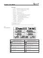
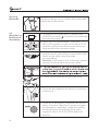
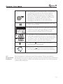
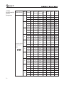
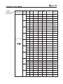
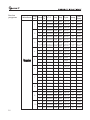
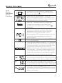
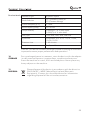
Download INSTRUCTION MANUAL - Current Solutions

Transcript
INSTRUCTION MANUAL
CAUTION: United States Federal Law restricts this
device to sale by or on the order of a physician
www.currentsolutionsnow.com
This manual is valid for the Quattro TM II
This user manual is published by Current Solutions™, LLC
Current Solutions™, LLC reserves the right to improve and amend it at any
time without prior notice. Amendments may however be published in new
editions of this manual.
All Rights Reserved.Rev.V1.0 © 2012
Declaration of conformity:
Current Solutions™, LLC. declares that the Quattro TM II
complies with following normative documents:
IEC60601-1, IEC60601-1-2, IEC60601-2-10, ISO 7010
ISO14971, ISO10993-1, ISO10993-5, ISO10993-10
Contents
1. FOREWORD...................................................................4
2. SAFETY INFORMATION................................................... 4
3. INDICATIONS FOR USE………………….............................. 7
4. PRESENTATION…........................................................... 8
5. INSTALLATION.............................................................. 10
6. OPERATION……………………………………………………....11
7. MAINTENANCE……………..……………….........................29
8. TROUBLESHOOTING ….................................................30
9. SPECIFICATIONS…………..…….................................…..31
10.STORAGE …………………………………….........................33
11.DISPOSAL……………………...........…………………………..33
12.EMC TABLE………….…................................……………...34
13.WARRANTY…..…....................................................…...38
14.NORMALIZED SYMBOLS……………………......……………...39
3
1.
FOREWORD
1.1
General
information
Thank you for purchasing the Quattro II . The microprocessor
TM
controlled Quattro II provides interferential (4-pole),
premodulated (2-pole interferential), medium frequency (Russian), EMS
and TENS waveform. You can choose between several different amplitude
modulation options. The interferential and premodulated modes offer
frequency modulation as well as a static frequency option.
1.2
Introduction
to This
Manual
This manual has been written for the users of Quattro II . It
contains general information on the operation, precautionary practices,
and maintenance information. In order to maximize its use, efficiency,
and the life of the system, please read this manual thoroughly and
become familiar with the controls, as well as the accessories before
operating the system.
TM
TM
2.
SAFETY
INFORMATIONS
2.1
Caution
4
1) Keep yourself informed of the contraindications.
2) Read, understand, and practice the warnings, cautions and operating
instructions. Know the limitations and hazards associated with using
any device. Observe the precautionary and operational decals placed
on the unit. Always follow the operating instructions prescribed by your
healthcare practitioner
3) DO NOT operate this unit in an environment where other devices are
being used that intentionally radiates electromagnetic energy in an
unshielded manner.
4) DO NOT use sharp objects such as a pencil point or ballpoint pen to
operate the buttons on the control panel.
5) Inspect Applicator cables and associated connectors before each use.
6) This device should not be used adjacent to or stacked with other
equipment and that if adjacent or stacked use is necessary, this
machine should be observed to verify normal operation in the
configuration in which it will be used.
7) This device needs special precautions regarding EMC and needs to be
installed and put into service according to the EMC information
provided in the manual.
8) Portable and mobile RF communications equipment can affect this
device. Do not use a mobile phone or other device that emit
electromagnetic fields, near the unit. This may result in incorrect
operation of the device.
9) This device has been thoroughly test and inspected to assure proper
performance and operation!
2.2
WARNING
1 ) U.S.A. Federal Law restricts these devices to sale by, or on the order
of, a physician or licensed practitioner. This device should be used
only under the continued supervision of a physician or licensed
practitioner.
2) Make certain the unit is electrically grounded by connecting only to a
grounded electrical service receptacle conforming to the applicable
national and local electrical codes.
3) Care must be taken when operating this equipment around other
equipment. Potential electromagnetic or other interference could
occur to this or to the other equipment. Try to minimize this
interference by not using other equipment in conjunction with it.
4) Before administering any treatment to a patient you should become
acquainted with the operating procedures for each mode of
treatment available, as well as the indications, contraindications,
warnings and precautions. Consult other resources for additional
information regarding the application of electrotherapy.
5) To prevent electrical shock, disconnect the unit from the power
source before attempting any maintenance procedures.
6) The use of accessories, transducers and cables than those specified,
with the exception of transducers and cables sold by the
manufacturer as replacement parts for internal components, may
result in increased emissions or decreased immunity of the device.
7) This device is not designed to be use in an MRI Environment and
should be removed prior to MRI exposure.
8) Do not apply stimulation over the patient's neck because this could
cause severe muscle spasms resulting in closure of the airway,
difficulty in breathing, or adverse effects on heart rhythm or blood
pressure;
9) Do not apply stimulation across the patient's chest, because the
introduction of electrical current into the chest may cause rhythm
disturbances to the patient's heart, which could be lethal;
10) Do not apply stimulation over open wounds or rashes, or over
swollen, red, infected, or inflamed areas or skin eruptions (e.g.,
phlebitis, thrombophlebitis, varicose veins);
11) Do not apply stimulation over, or in proximity to, cancerous lesions;
12) Do not apply stimulation in the presence of electronic monitoring
equipment (e.g., cardiac monitors, ECG alarms), which may not
operate properly when the electrical stimulation device is in use;
13) Do not apply stimulation when the patient is in the bath or shower;
14) Do not apply stimulation while the patient is sleeping; and
5
15) Do not apply stimulation while the patient is driving, operating
machinery, or during any activity in which electrical stimulation can
put the patient at risk of injury.
16) Consult with the patient's physician before using this device, because
the device may cause lethal rhythm disturbances to the heart in
susceptible individuals; and
17) Apply stimulation only to normal, intact, clean, healthy skin.
18) This device should not be used for symptomatic local pain relief
unless etiology is established or unless a pain syndrome has been
diagnosed.
19) Patients with arterial or venous thrombosis or thrombophlebitis are
at risk of developing embolisms when electrical stimulation is
applied over or adjacent to the vessels containing the thrombus. If a
patient has a history of deep vein thrombosis, even many years past,
the affected area should not be stimulated.
20) Fresh fractures should not be stimulated in order to avoid unwanted
motion.
21) Stimulation should not be applied immediately following trauma or
to tissues susceptible to hemorrhage.
22) Do not apply electrodes directly over the eyes or inside body cavities.
23) Do not use electrical stimulation in conjunction with high frequency
surgical equipment or microwave or shortwave therapy systems.
24) Keep electrodes separated during treatment. Electrodes in contact
with each other could result in improper stimulation or skin burns.
25) Since the effects of stimulation of the brain are unknown, stimulation
should not be applied across the head, and electrodes should not be
placed on opposite sides of the head.
2.3
1 ) Do not use this device on patients who have a cardiac pacemaker,
CONTRAIimplanted defibrillator, or other implanted metallic or electronic
NDICATIONS
device, because this may cause electric shock, burns, electrical
interference, or death.
2) Do not use this device on patients whose pain syndromes are
undiagnosed.
2.4
1)
PRECAUTIONS
2)
3)
4)
Federal law (USA) restricts this device to sale by or on the order of a
physician.
The long-term effects of chronic electrical stimulation are unknown.
Electrical stimulation devices have no curative value.
Electrical stimulation is not a substitute for pain medications and
other pain management therapies
5) Effectiveness is highly dependent upon patient selection by a
practitioner qualified in the management of pain patients;
6) The safety of electrical stimulation during pregnancy has not been
established;
6
7) Some patients may experience skin irritation or hypersensitivity due
to the electrical stimulation or electrical conductive medium (gel);
8 ) Patients with suspected or diagnosed heart disease should follow
precautions recommended by their physicians; and
9 ) Patients with suspected or diagnosed epilepsy should follow
precautions recommended by their physicians.
10) Use caution when the patient has a tendency to bleed internally, such
as following an injury or fracture;
11) Use caution following recent surgical procedures when stimulation
may disrupt the patient's healing process;
12) Use caution if stimulation is applied over the menstruating or
pregnant uterus; and
13) Use caution if stimulation is applied over areas of skin that lack
normal sensation.
14) Use this device only under the continued supervision of a licensed
practitioner.
15) Electrical stimulation is ineffective for pain of central origin.
16) Use extreme caution when treating desensitized areas or on patients
who may not be able to report discomfort or pain
17) Patients should not be left unattended during any treatment.
18) Keep this device out of the reach of children;
2.5
Adverse
reaction
Skin irritation, inflammation, and electrode burns beneath the
electrodes are potential adverse reactions.
Patients may experience headache and other painful sensations
during or following the application of electrical stimulation near the
eyes and to the head and face; and
Patients should stop using the device and should consult with their
physicians if they experience adverse reactions from the device.
3.
INDICATIONS
FOR USE
For TENS, Interferential and premodulated(IFC):
1. Symptomatic relief of chronic intractable pain;
2. Reduction of inflammation;
3. Post-traumatic acute pain and edema;
4. Post-surgical acute pain and edema.
Additionally for EMS and Russian:
1. Relaxation of Muscle spasms and edema reduction,
2. Prevention or retardation of disuse atrophy,
3. Increasing local blood circulation,
4. Muscle re-education,
5. Maintaining or increasing range of motion,
6. Immediate postsurgical stimulation of calf muscles to prevent venous
thrombosis.
7
4.
PRESENTATION
1
2
6
7
8
4.1
Panel For
front view
B2
B4
3
B6
B8
B1
B3
B5
B7
9
4
5
DC15V/1.2A
4
10
2
3
11
12
1)
2)
3)
4)
5)
6)
7)
8)
9)
8
Adjust the output intensity of channel 1.
Adjust the output intensity of channel 2.
Parameters control knob and pause button.
Stop treatment button.
Power indicator.
LCD display: Shows the current information of the device.
Adjust the output intensity of channel 3.
Adjust the output intensity of channel 4.
Eight parameters selection buttons, see below for details:
B1: Toggle the therapeutic waveform.
B2: Toggle the therapeutic program and select the output
mode (CC/CV).
B3: Toggle the parameter Vector/Duty/F.M./Burst
B4: Toggle the parameter Freq./C.F.
B5: Toggle the parameter Beat H./A.M.
B6: Toggle the parameter Beat L./P.Dur.
B7: Toggle the parameter Treat./Cycle/Ramp time
B8: Step button
1
Remark:
CC — Constant current output mode.
CV — Constant voltage output mode.
F.M. — Frequency Modulation
Burst— Burst Frequency
Freq. — Frequency
C.F. — Carrier Frequency
Duty — Duty Cycle for Russian waveform
Beat H. — Sweep High Beat Frequency
A.M. — Amplitude Modulation
Beat L. — Sweep Low Beat Frequency
P.Dur. — Pulse Duration
Treat. — Treatment time
Cycle— Cycle time
Ramp— Ramp time
10) Adapter receptacle
11) ON/OFF switch
12) Output connector: connect with connector of cable
4.2
User Interface
Symbol definitions
IFC- Interferential
(Traditional 4 Pole)
Symbol definitions
Premodulated
(Traditional 2 Pole IFC)
Electrical stimulation
Time indicator
Electrical output channel 1
indicator
Electrical output channel 2
indicator
Electrical output channel 3
indicator
Electrical output channel 4
indicator
Constant current control
Constant Voltage control
9
5.
INSTALLATION
5.1
Before Use
Remove the equipment and all accessories from shipping carton and
box. Visually check if there is any damage or missing parts or accessories.
If yes, please report to local dealer or retailer where you purchase this unit.
TM
Your Quattro II equipment contains the following accessories.
1
4
3
2
5
6
7
8
10
9
11
12
INSTRUCTION MANUAL
CAUTION: United States Federal Law restricts this
device to sale by or on the order of a physician
www.currentsolutionsnow.com
Part
10
Quantity
1
Rubber Electrodes,60x90mm
4pcs
2
Rubber Electrodes,70x110mm
4pcs
3
Electrode Sponges,70x100mm
4pcs
4
Electrode Sponges,80x120mm
4pcs
5
Self-adhesive Electrodes,50x50mm
8pcs
6
Self-adhesive Electrodes,50x100mm
8pcs
7
Elastic Wrap,75x1200mm
2pcs
8
Elastic Wrap ,75x600mm
2pcs
9
Electrode wires (black/red)
4pcs
10
Adapter 100-240V/50-60Hz
1pc
11
Connector of cable
2pcs
12
User Manual
1pc
5.2
Connection
of the power
adapter
Connect the power adapter to the device connector.
Connect the power adapter to a wall socket.
Caution:
Prior to connecting this apparatus to the power supply, check that the
voltage and frequency stated on the rating label match with the
available power supply.
The power adapter is a part of the supply circuit on which the device's
TM
safety partly depends. The approvals for Quattro II are only
valid if used in combination with this type of adapter.
5.3
Switch on the device, using ON/OFF switch ( 11).
Switching on
5.4
Switching off
and
disconnect
power adapter
Switch off the device by switching the ON/OFF switch from [ ] to
[ ] position.
Pull out the power adapter from the wall socket.
Pull out the power adapter from device.
6.
OPERATION
6.1
Measures
with regard
to treatments
6.1.1
Electrotherapy
Before
the
treatment
Ensure there are no contraindications to treatment.
Inspect the treatment area skin seriously for any abrasions,
inflammation, surface veins etc.
Clean the skin of the treatment area with soap or alcohol (70%).
If the skin is hairy, shaving can get optimal treatment.
Test the heat sensibility of the treatment area.
6.1.2
Electrode
Placement
Examine the skin for any wounds and clean the skin.
Apply the electrodes to the treatment area.
Ensure that the electrodes are applied securely to the skin.
Ensure good contact between each electrode and the skin.
Check the electrode contact regularly during the treatment.
Examine the skin again after the treatment.
Choose electrodes that fit the anatomy.
Follow electrode manufacturer’s instructions.
To avoid skin irritation due to high current density, do not use
electrodes smaller in surface area than 25cm 2 self-adhesive
electrode.
11
Caution
Keep electrodes separated during treatment. Electrodes in contact
with each other could result in improper stimulation or skin burns.
Output current density is related to electrode size. Improper
application may result in patient injury. If any question arises as to
the proper electrode size, consult a licensed practitioner prior to
therapy session.
Powered muscle stimulators should be used only with the leads and
electrodes recommended by the manufacturer.
6.1.3
Adhesive
electrodes
This device is supplied with 8 pieces 50mm×50mm and 8 pieces
50mm×100mm adhesive electrodes. You can select the right adhesive
electrodes according to treatment area and output current density.
It is recommended that manufacturer's Electrodes be used whenever
possible to ensure the highest level of contact with the treatment area
and most uniform delivery of the prescribed electrotherapy treatment.
Properly dispose of used Electrodes upon completion of the therapy
session.
If you are unsure of your electrode adhesive properties, order new
replacement electrodes. Replacement electrodes should be re-ordered
through or on the advice of your physician to ensure proper quality.
Apply electrodes to the exact site indicated by your physician or therapist,
before applying electrodes, be sure the skin surface over which electrodes
are placed is thoroughly cleaned and dried. Make sure the electrodes are
placed firmly to the skin and make good contact between the skin and the
electrodes. Place the electrodes over the skin; attach them properly,
firmly, and evenly.
Caution:
12
1) Before applying the self-adhesive electrodes, it is recommended to
wash and degrease the skin, and then dry it.
2) Do not turns on the device when the electrodes are not positioned on
the body.
3) Never remove the self-adhesive electrodes from the skin while the
device is still turns on.
4) It is recommended that, at minimum, 50mm x 50mm self-adhering
based, square electrodes are used at the treatment area.
Electrode
Instructions
Connecting
Lead Wires
Securing
Electrodes
6.1.4.
Rubber
electrodes
Reusable
rubber
Electrodes
Connecting
Lead Wires
Conductive
Medium 1
Conductive
Medium 2
Insert the lead with the Red (+) electrode
connector into one adhesive Electrode. Insert the
lead with the Black (-) electrode connector into
the other electrode. Make certain the lead wires
are seated completely into the electrodes, there
are no bare metal of the pins exposed.
Remove the adhesive Electrodes from the
protective backing and apply to the treatment
area as prescribed. Ensure that the entire
electrode surface is in contact with patient skin
by pressing into place.
If used for delivery of electrotherapy, there are two conductive
mediums for you to select, the first one is use electrode sponges as
conductive mediums, another is use other conductive medium such
as Transmission Gel.
These Rubber Electrodes should be secured to the treatment area
using the Nylon Wraps shipped with the Therapy System.
Insert the lead with the Red (+) electrode
connector into one rubber electrode. Insert the
lead with the Black (-) electrode connector into
the other rubber electrode. Make certain the lead
wires are seated completely into the electrodes.
Inserted the Rubber Electrodes into the electrode
sponges moistened with distilled water prior to
placement on the patient.
Liberally apply Transmission Gel to electrode
prior to placement on patient.
Please note: Please purchase the Transmission gel
with CE mark or that is cleared by the FDA.
13
Securing
Electrodes
6.2
Quick Set-up
for Electrical
Stimulation
Use Nylon Wrap to secure each rubber electrode
in position on the patient.
1. In order to turn on the device, please press
ON/OFF switch to [ ] icon which is located on
the side of the device
2. When you turn the Quattro II on, the
device will get down to self- check about 6~8
seconds, and then the default parameters are
displayed the last treatment mode.
TM
3. Connect the electrode wires to the cable;
please note the color of the wires and the color
marks on the cable, they should be
corresponding.
Caution: If you want to use 4 channels, please
connect all electrode wires to two cables.
2
5. Connect the electrodes to electrode wires.
6. Place the electrodes on the patient according
to section 6.1.
7. There are 5 therapeutic waveforms for you to
select. Press the “ Waveform” button to toggle
the therapeutic waveform, and then rotating
the Parameters control knob (③) to select
waveform like IF-4P, IF-2P, TENS, EMS and
Russian.
14
8. Each therapeutic waveform has 10 programs.
The details parameters for each program
please refer to section 6.3 in this manual.
Press the “B2”Program button to toggle the
therapeutic program, and then rotating the
Parameters control knob to select the
therapeutic programs in corresponding
waveform.
9. Press “B2” Program button to select “CC ” or
“CV ” control mode.
10. Adjust the output intensity and start electrical
treatment that you are using by rotating the
output intensity adjustable knobs on the
control panel. 0.5mA/step or 0.5V/step.
11. For safety using, load detection was designed
in this device after the output intensity surpass
10.0mA/10.0V. If there are no electrodes stuck
on patient ’ skin, an alarm buzzer sound will
appear and the intensity value flashing.
12. Press the “ ” button to stop treatment if
any emergency happened.
13. Press the “
” button to pause treatment;
you can press it again to restart the treatment.
6.3
Using Preset
Programs
Each therapeutic waveform has 10 programs. They have default
parameters for each program, but you can set and save the parameters
according to patient ’s need. the default parameters for each program
please refer to below:
15
4-Pole
Interferential
preset
programs
Waveform
ProgCC/ Vector Vector
Beat. Beat. Treat.
C.F.
Phase
Time
H
L
ram
CV (Auto) (Manual)
1
2
3
4
5
Interferential
Traditional
(4P)
6
7
8
9
10
16
1
CC
0
45
4kHz 110Hz 100Hz 15min
2
CC
0
45
4kHz 110Hz 100Hz 0min
3
CC
0
45
4kHz 110Hz 100Hz 0min
1
CC
0
45
4kHz 150Hz 100Hz 10min
2
CC
0
45
4kHz 150Hz 100Hz 0min
3
CC
0
45
4kHz 150Hz 100Hz 0min
1
CC
0
45
4kHz 50Hz 50Hz 15min
2
CC
0
45
4kHz 50Hz 50Hz 0min
3
CC
0
45
4kHz 50Hz 50Hz 0min
1
2
CC
CC
0
0
45
45
4kHz 150Hz 90Hz 15min
4kHz 150Hz 90Hz 0min
3
CC
0
45
4kHz 150Hz 90Hz 0min
1
CC
0
45
4kHz 110Hz 100Hz 15min
2
CC
0
45
4kHz 110Hz 100Hz 0min
3
CC
0
45
4kHz 110Hz 100Hz 0min
1
CC
0
45
4kHz 110Hz 100Hz 15min
2
CC
0
45
4kHz 110Hz 100Hz 15min
3
CC
0
45
4kHz 110Hz 100Hz 15min
1
CC
0
45
4kHz 110Hz 100Hz 15min
2
CC
0
45
4kHz 110Hz 100Hz 15min
3
CC
0
45
4kHz 110Hz 100Hz 15min
1
CC
0
45
4kHz 110Hz 100Hz 15min
2
CC
0
45
4kHz 110Hz 100Hz 15min
3
CC
0
45
4kHz 110Hz 100Hz 15min
1
CC
0
45
4kHz 110Hz 100Hz 15min
2
CC
0
45
4kHz 110Hz 100Hz 15min
3
CC
0
45
4kHz 110Hz 100Hz 15min
1
CC
0
45
4kHz 110Hz 100Hz 15min
2
CC
0
45
4kHz 110Hz 100Hz 15min
3
CC
0
45
4kHz 110Hz 100Hz 15min
2-Pole
Interferential
programs
Waveform
ProgCC/
Phase
ram
CV
1
2
3
4
IFC Premod.
(2P)
5
6
7
8
9
10
C.F.
Beat. Beat.
H
L
Cycle
Treat.
Time
1
CC 2500Hz 110Hz 100Hz continuous 15min
2
CC 2500Hz 110Hz 100Hz continuous 0min
3
CC 2500Hz 110Hz 100Hz continuous 0min
1
CC 2500Hz 150Hz 100Hz continuous 10min
2
CC 2500Hz 150Hz 100Hz continuous 0min
3
CC 2500Hz 150Hz 100Hz continuous 0min
1
CC 2500Hz 50Hz 50Hz continuous 15min
2
CC 2500Hz 50Hz 50Hz continuous 0min
3
CC 2500Hz 50Hz 50Hz continuous 0min
1
CC 2500Hz 150Hz 90Hz continuous 15min
2
CC 2500Hz 150Hz 90Hz continuous 0min
3
CC 2500Hz 150Hz 90Hz continuous 0min
1
CC 2500Hz 110Hz 100Hz continuous 15min
2
CC 2500Hz 110Hz 100Hz continuous 0min
3
CC 2500Hz 110Hz 100Hz continuous 0min
1
CC 2500Hz 110Hz 100Hz continuous 15min
2
CC 2500Hz 110Hz 100Hz continuous 15min
3
CC 2500Hz 110Hz 100Hz continuous 15min
1
CC 2500Hz 110Hz 100Hz continuous 15min
2
CC 2500Hz 110Hz 100Hz continuous 15min
3
CC 2500Hz 110Hz 100Hz continuous 15min
1
CC 2500Hz 110Hz 100Hz continuous 15min
2
CC 2500Hz 110Hz 100Hz continuous 15min
3
CC 2500Hz 110Hz 100Hz continuous 15min
1
CC 2500Hz 110Hz 100Hz continuous 15min
2
CC 2500Hz 110Hz 100Hz continuous 15min
3
CC 2500Hz 110Hz 100Hz continuous 15min
1
CC 2500Hz 110Hz 100Hz continuous 15min
2
CC 2500Hz 110Hz 100Hz continuous 15min
3
CC 2500Hz 110Hz 100Hz continuous 15min
17
TENS
programs
Waveform
ProgCC/
P.
F.M. Burst Freq A.M.
Phase
Dur.
ram
CV
1
2
3
4
5
6
7
8
9
10
18
Cycle Treat.
Time
1
CC
0
0 120Hz 0% 70μs continuous 14min
2
CC
0
0 120Hz 0% 70μs continuous 0min
3
CC
0
0 120Hz 0% 70μs continuous 0min
1
CC
0
0 200Hz 0% 60μs continuous 20min
2
CC
0
0 200Hz 0% 60μs continuous 0min
3
CC
0
0 200Hz 0% 60μs continuous 0min
1
CC
0
0
10Hz 0% 180μs continuous 14min
2
CC
0
0
10Hz 0% 180μs continuous 0min
3
CC
0
0
10Hz 0% 180μs continuous 0min
1
CC
0
0
80Hz 0% 100μs continuous 30min
2
CC
0
0
80Hz 0% 100μs continuous 0min
3
CC
0
0
80Hz 0% 100μs continuous 0min
1
CC 50Hz
0 180Hz 0% 30μs continuous 16min
2
CC 50Hz
0 180Hz 0% 30μs continuous 0min
3
CC 50Hz
0 180Hz 0% 30μs continuous 0min
1
CC
0
0 120Hz 0% 70μs continuous 14min
2
CC
0
0 120Hz 0% 70μs continuous 14min
3
CC
0
0 120Hz 0% 70μs continuous 14min
1
CC
0
0 120Hz 0% 70μs continuous 14min
2
CC
0
0 120Hz 0% 70μs continuous 14min
3
CC
0
0 120Hz 0% 70μs continuous 14min
1
CC
0
0 120Hz 0% 70μs continuous 14min
2
CC
0
0 120Hz 0% 70μs continuous 14min
3
CC
0
0 120Hz 0% 70μs continuous 14min
1
CC
0
0 120Hz 0% 70μs continuous 14min
2
CC
0
0 120Hz 0% 70μs continuous 14min
3
CC
0
0 120Hz 0% 70μs continuous 14min
1
CC
0
0 120Hz 0% 70μs continuous 14min
2
CC
0
0 120Hz 0% 70μs continuous 14min
3
CC
0
0 120Hz 0% 70μs continuous 14min
EMS
programs
Waveform
ProgCC/
P.
F.M. Burst Freq A.M.
Phase
Dur.
ram
CV
1
2
3
4
5
6
7
8
9
10
Cycle Treat.
Time
1
CC
0
0 120Hz 0% 70μs continuous 14min
2
CC
0
0 120Hz 0% 70μs continuous 0min
3
CC
0
0 120Hz 0% 70μs continuous 0min
1
CC
0
0 200Hz 0% 60μs continuous 20min
2
CC
0
0 200Hz 0% 60μs continuous 0min
3
CC
0
0 200Hz 0% 60μs continuous 0min
1
CC
0
0
10Hz 0% 180μs continuous 20min
2
CC
0
0
10Hz 0% 180μs continuous 0min
3
CC
0
0
10Hz 0% 180μs continuous 0min
1
CC
0
0
80Hz 0% 100μs continuous 30min
2
CC
0
0
80Hz 0% 100μs continuous 0min
3
CC
0
0
80Hz 0% 100μs continuous 0min
1
CC 50Hz
0 180Hz 0% 30μs continuous 16min
2
CC 50Hz
0 180Hz 0% 30μs continuous 0min
3
CC 50Hz
0 180Hz 0% 30μs continuous 0min
1
CC
0
0 120Hz 0% 70μs continuous 14min
2
CC
0
0 120Hz 0% 70μs continuous 14min
3
CC
0
0 120Hz 0% 70μs continuous 14min
1
CC
0
0 120Hz 0% 70μs continuous 14min
2
CC
0
0 120Hz 0% 70μs continuous 14min
3
CC
0
0 120Hz 0% 70μs continuous 14min
1
CC
0
0 120Hz 0% 70μs continuous 14min
2
CC
0
0 120Hz 0% 70μs continuous 14min
3
CC
0
0 120Hz 0% 70μs continuous 14min
1
CC
0
0 120Hz 0% 70μs continuous 14min
2
CC
0
0 120Hz 0% 70μs continuous 14min
3
CC
0
0 120Hz 0% 70μs continuous 14min
1
CC
0
0 120Hz 0% 70μs continuous 14min
2
CC
0
0 120Hz 0% 70μs continuous 14min
3
CC
0
0 120Hz 0% 70μs continuous 14min
19
Russian
programs
Waveform
ProgCC/
C.F. Freq. Duty Cycle
Phase
ram
CV
1
2
3
4
5
6
7
8
9
10
20
Ramp Treat.
Time
1
CC 2500Hz 50Hz 50% 10s/10s
1s
10min
2
CC 2500Hz 50Hz 50% 10s/10s
1s
0min
3
CC 2500Hz 50Hz 50% 10s/10s
1s
0min
1
CC 2500Hz 50Hz 50%
4s/12s
1s
10min
2
CC 2500Hz 50Hz 50%
4s/12s
1s
0min
3
CC 2500Hz 50Hz 50%
4s/12s
1s
0min
1
CC 2500Hz 50Hz 50%
4s/12s
1s
10min
2
CC 2500Hz 50Hz 50%
4s/12s
1s
0min
3
CC 2500Hz 50Hz 50%
4s/12s
1s
0min
1
CC 2500Hz 50Hz 50% 10s/10s
1s
10min
2
CC 2500Hz 50Hz 50% 10s/10s
1s
0min
3
CC 2500Hz 50Hz 50% 10s/10s
1s
0min
1
CC 2500Hz 50Hz 50%
5s/5s
1s
20min
2
CC 2500Hz 50Hz 50%
5s/5s
1s
0min
3
CC 2500Hz 50Hz 50%
5s/5s
1s
0min
1
CC 2500Hz 50Hz 50% 10s/10s
1s
10min
2
CC 2500Hz 50Hz 50% 10s/10s
1s
10min
3
CC 2500Hz 50Hz 50% 10s/10s
1s
10min
1
CC 2500Hz 50Hz 50% 10s/10s
1s
10min
2
CC 2500Hz 50Hz 50% 10s/10s
1s
10min
3
CC 2500Hz 50Hz 50% 10s/10s
1s
10min
1
CC 2500Hz 50Hz 50% 10s/10s
1s
10min
2
CC 2500Hz 50Hz 50% 10s/10s
1s
10min
3
CC 2500Hz 50Hz 50% 10s/10s
1s
10min
1
CC 2500Hz 50Hz 50% 10s/10s
1s
10min
2
CC 2500Hz 50Hz 50% 10s/10s
1s
10min
3
CC 2500Hz 50Hz 50% 10s/10s
1s
10min
1
CC 2500Hz 50Hz 50% 10s/10s
1s
10min
2
CC 2500Hz 50Hz 50% 10s/10s
1s
10min
3
CC 2500Hz 50Hz 50% 10s/10s
1s
10min
6.4
Each stimulation
set-up procedure
6.4.1
4-Pole
Interferential
Stimulation
Set-up
Procedure
1. In order to turn on the device, please press
ON/OFF switch to [ ] icon which is located on
the side of the device.
2. When you turn the Quattro II , the
device will get down to self- check about 6~8
seconds, and then the default parameters are
displayed the last treatment mode.
TM
3. Press “B1” Waveform button to toggle the
therapeutic waveform, then rotating the
parameters control knob (③) to select “ ”
waveform.
4. Press “B2” Program button to toggle the
therapeutic program, and then rotating the
parameters control knob (③) to select the
therapeutic programs from P01 to P10.
Each program has 3 treatment phases, you can
set and save the parameters according to
patient ’s need.
5. Press “B2” Program button to select “CC ” or
“CV ” control mode.
6. There are two modes in Quattro II , press and
hold “”B8” button to switch Normal mode and
Professional mode. In professional mode, each
program has 3 treatment phase, the LCD
display like left figure. Rotating the parameters
control knob (③) to select phase program from
1 to 3 when the device enter into professional
mode. The parameters of each phase program
can be set according to following methods.
TM
7. Press “B3” button to toggle Vector parameter,
then rotating the parameters control knob (③) to
set the vector (manual) parameter from 0°to
90°,15°/step.
8. Press “B3”button again, the vector parameter
change to auto mode, the LCD display “0%”
like left figure. rotating the parameters control
knob (③) to set the vector (auto) parameter from
0 % to 100%, 20%/step.
21
9. Press “B5” button to toggle Beat H. parameter,
then rotating the parameters control knob (③)
to set the parameter from (Beat. L) Hz to
150Hz, 1Hz/step.
10. Press “B6” button to toggle Beat L . parameter,
then rotating the adjust parameters contorl
knob (③) to set the parameter from 1Hz to
(Beat. H)Hz, 1Hz/step.
11. Press “B7” button to toggle Treat. time
parameter, then rotating the parameters
control knob (③) to set the treatment time
from 1min to 60min, 1min/step.
12. Stick the electrodes on the patient. You will
need two electrodes for each channel, four
in total.
①
②
13. Adjust the output intensity and start electrical
treatment that you are using by rotating the
output intensity adjustable knobs on the
control panel. 0.5mA/step or 0.5V/step.
For safety using, load detection was designed
in this device after the output intensity
surpass 10.0mA/10.0V. If there are no
electrodes stuck on patient ’ skin, an
alarm buzzer sound will appear and the
intensity value flashing.
14. Press the “ ” button to stop treatment if
any emergency happened.
15. Press the “
” button to pause treatment;
you can press it again to restart the treatment.
22
6.4.2
2-Pole
Interferential
Stimulation
Set-up
Procedure
1. In order to turn on the device, please press
ON/OFF switch to[ ] icon which is located on
the side of the device.
2. When you turn the Quattro II on, the
device will get down to self- check about 6~8
seconds, and then the default parameters are
displayed the last treatment mode.
TM
3. Press “B1” Waveform button to toggle the
therapeutic waveform, then rotating the
parameters control knob (③) to select “
”
waveform.
4. Press “B2” Program button to toggle the
therapeutic program, and then rotating the
parameters control knob (③) to select the
therapeutic programs from P01 to P10.
Each program has 3 treatment phases, you can
set and save the parameters according to
patient ’s need.
5. Press “B2” Program button to select “CC ” or
“CV ” control mode.
6. There are two modes in Quattro II , press and
hold ”B8” button to switch Normal mode and
Professional mode. In professional mode, each
program has 3 treatment phase, the LCD
display like left figure. Rotating the parameters
control knob (③) to select phase program from
1 to 3 when the device enter into professional
mode. The parameters of each phase program
can be set according to following methods.
TM
8. Press “B5” button to toggle Beat H. parameter,
then rotating the parameters control knob (③) to
set the parameter from (Beat. L) Hz to 150Hz,
1Hz/step.
9. Press “B6” button to toggle Beat L . parameter,
then rotating the parameters control knob (③)
to set the parameter from 1Hz to (Beat. H)Hz,
1Hz/step.
10. Press “B7” button to toggle Treat. time
parameter, then rotating the parameters
control knob (③) to set the treatment time
from 1min to 60min, 1min/step.
23
11. Press “B7” button again to toggle Cycle time
parameter, then rotating the parameters
control knob (③) to select the cycle time
(work time/rest time) from “-/-(continuous)
”, “5/5”, “4/12”, “10/10”, “10/20”,
“10/30” and “10/50”.
12. Stick the electrodes on the patient. You can
use one or two channel as your needs.
13. Adjust the output intensity and start electrical
treatment that you are using by rotating the
output intensity adjustable knob on the
control panel. 0.5mA/step or 0.5V/ step.
For safety using, load detection was designed
in this device after the output intensity surpass
10. 0mA/10. 0V. If there are no electrodes
stuck on patient ’ skin, an alarm buzzer sound
will appear and the intensity value flashing.
14. Press the “ ” button to stop treatment if any
emergency happened.
15. Press the “
” button to pause treatment;
you can press it again to restart the treatment.
24
6.4.3
TENS
and EMS
Stimulation
Set-up
Procedure
1. In order to turn on the device, please press
ON/OFF switch to [ ] icon which is located
on the side of the device.
2. When you turn the Quattro II on, the
device will get down to self- check about 6~8
seconds, and then the default parameters are
displayed the last treatment mode.
TM
/
3. Press “B1” Waveform button to toggle the
therapeutic waveform, then rotating the
parameters control knob (③) to select TENS or
EMS waveform.
4. Press “B2” Program button to toggle the
therapeutic program, and then rotating the
parameters control knob (③) to select the
therapeutic programs from P01 to P10.
Each program has 3 treatment phases, you can
set and save the parameters according to
patient ’s need.
5. Press “B2” Program button to select “CC ” or
“CV ” control mode.
6. There are two modes in Quattro II , press and
hold ”B8” button to switch Normal mode and
Professional mode. In professional mode, each
program has 3 treatment phase, the LCD
display like left figure. Rotating the parameters
control knob (③) to select phase program from
1 to 3 when the device enter into professional
mode. The parameters of each phase program
can be set according to following methods.
TM
7. Press “B3” button to toggle F.M. parameter,
then rotating the parameters control knob (③)
to set the F.M. parameter from 0Hz to 249Hz,
1Hz/step. But F.M.+Freq.≤250Hz.
8. Press “B3”button again to toggle Burst rate,
then rotating the parameters control knob (③)
to set the Burst rate from 0Hz to 10Hz, 1Hz/step.
But Burst×8≤Freq.
9. Press “B4” button to toggle Freq. parameter,
then rotating the parameters control knob (③)
to set the frequency from 1Hz to250Hz,
1Hz/step.
But Freq. ≥Burst x 8 or Freq.≤ 250-F.M.
25
10. Press “B5” button to toggle A.M. parameter,
then rotating the parameters control knob (③)
to set the parameter from 0% to100%, (0%
means the output intensity always in setting
value; 100% means the output intensity
changes form 0 to setting value) 20%/step.
11. Press “B6” button to toggle P.Dur. parameter,
then rotating the parameters control knob (③)
to set the pulse duration from 30µs to 400µs,
5µs/step.
12. Press “B7” button to toggle Treat. time
parameter, then rotating the parameters
control knob (③) to set the treatment time
from 1min to 60min, 1min/step.
13. Press “B7” button again to toggle Cycle time
parameter, then rotating the parameters
control knob (③) to select the cycle time (work
time/rest time)from “-/-(continuous)”, “4/4
”, “4/8”, “7/7”, “5/5”, “4/12”, “10/10”, “
10/20”, “10/30” and “10/50”.
14. Stick the electrodes on the patient. You can
use one or two channel as your needs.
15. Adjust the output intensity and start electrical
treatment that you are using by rotating the
output intensity adjustable knob on the
control panel. 0.5mA/step or 0.5V/ step.
For safety using, load detection was designed
in this device after the output intensity surpass
10. 0mA/10. 0V. If there are no electrodes
stuck on patient ’ skin, an alarm buzzer sound
will appear and the intensity value flashing.
16. Press the “ ” button to stop treatment if
any emergency happened.
17. Press the “
” button to pause treatment;
you can press it again to restart the treatment.
26
6.4.4
Russian
Stimulation
Set-up
Procedure
1. In order to turn on the device, please press
ON/OFF switch to [ ] icon which is located
on the side of the device.
2. When you turn the Quattro II on, the
device will get down to self- check about 6~8
seconds, and then the default parameters are
displayed the last treatment mode.
TM
3. Press “B1” Waveform button to toggle the
therapeutic waveform, then rotating the
parameters control knob (③) to select “ ”
waveform.
4. Press “B2” Program button to toggle the
therapeutic program, and then rotating the
parameters control knob (③) to select the
therapeutic programs from P01 to P10.
Each program has 3 treatment phases, you can
set and save the parameters according to
patient ’s need.
5. Press “B2” Program button to select “CC ” or
“CV ” control mode.
6. There are two modes in Quattro II , press and
hold ”B8” button to switch Normal mode and
Professional mode. In professional mode, each
program has 3 treatment phase, the LCD
display like left figure. Rotating the parameters
control knob (③) to select phase program from
1 to 3 when the device enter into professional
mode. The parameters of each phase program
can be set according to following methods.
TM
7. Press “B4” button to toggle Freq. parameter,
then rotating the parameters control knob (③) to
set the frequency from 20Hz to100Hz,5Hz/step.
8. Press “B3” button to toggle Duty parameter,
then rotating the parameters control knob (③) to
set the parameter from 10% to 50%, 10%/step.
9. Press “B7” button to toggle Treat. time
parameter, then rotating the parameters control
knob (③) to set the treatment time from 1min to
60min, 1min/step.
27
10. Press “B7” button again to toggle Cycle time
parameter, then rotating the parameters control
knob (③) to select the cycle time (work time/rest
time) from “-/-(continuous)”, ”5/5”, ”4/12”,
”10/10”,”10/20”, ”10/30” and ”10/50”.
11. Press “B7” button again to toggle Ramp time
parameter, then rotating the parameters
control knob (③) to select the ramp time
from 1s, 2s and 5s.
12. Stick the electrodes on the patient. You can
use one or two channel as your needs.
13. Adjust the output intensity and start electrical
treatment that you are using by rotating the
output intensity adjustable knob on the
control panel. 0.5mA/step or 0.5V/ step.
For safety using, load detection was designed
in this device after the output intensity surpass
10. 0mA/10. 0V. If there are no electrodes
stuck on patient ’ skin, an alarm buzzer sound
will appear and the intensity value flashing.
14. Press the “ ” button to stop treatment if
any emergency happened.
15. Press the “
” button to pause treatment;
you can press it again to restart the treatment.
Remark:
If you want to restore factory parameter settings, please firstly press and
hold knobs "①" and "②" at the same time, and then turn on the device
by pressing ON/OFF switch, keep pressing "①" and "②" knobs and the
device will keep pealing until all parameters restore factory settings.
28
7.
MAINTENANCE
7.1
Cleaning of
the device
Switch off the device and disconnect it from the power supply. The apparatus
can be cleaned with a damp cloth. Use lukewarm water and a non-abrasive
liquid household cleaner (no abrasive, no alcohol content solution). If a more
sterile cleaning is needed, use a cloth moistened with an antimicrobial cleaner.
Caution
Do not submerse the apparatus in liquids. Should the unit accidentally become
submersed, contact the dealer or Authorized Service center immediately.Do not
attempt to use a system that has been wet inside until inspected and tested by a
Service Technician Certified by Authorized Service center. Do not allow liquids to
enter the ventilation holes.
7.2
Cleaning the
electrodes
Apply the protective backing to the tacky side of the electrode. Place the
electrode on the side of the protective backing that is labeled with the word
on.
It may be helpful to improve repeated application by spreading a few drops
of cold water over the adhesive and turn the surface up to air dry. Over
Saturation with water will reduce the adhesive properties.
Between uses, store the electrodes in the reusable bag in a cool dry place.
Caution
The electrodes are intended for single patient use only.
If irritation occurs, discontinue use and consult your clinician.
Always use the electrodes with CE mark, or are legally marketed in
the US under 510(K) procedure.
7.3
Cleaning the
lead wires
and cables
7.4
Maintenance
Periodically wipe the lead wires clean with a cloth dampened in a mild soap
solution, and then gently wipe them dry. Use of rubbing alcohol on the lead
wires will damage the insulation and dramatically shorten their life.
Maintenance and all repairs should only be carried out by an authorized
agency. The manufacturer will not be held responsible for the results of
maintenance or repairs by unauthorized persons.
Opening of the equipment by unauthorized agencies is not allowed
and will terminate any claim to warranty.
29
8.
TROUBLESHOOTING
For optimal
use:
Replace lead wires annually.
Please follow the directions on the electrode packaging for the care
of electrodes. The life of the electrodes varies, depending on skin
conditions, skin preparation, storage and climate. Replace electrodes
that no longer stick.
NOTE: If the following measures fail to alleviate the problem, please
call your dealer.
Problem
Displays fail to
light up
Stimulation weak
Possible Cause
Adapter contact
failure
Electrodes
1. Dried out or
contaminated
2. Placement
Lead wires
Old/worn/damaged
Poor electrode contact
Stimulation stops
Stimulation is
uncomfortable.
Stimulation is
ineffective.
"E1" or "E2"
displays on LCD
30
Solution
Ensure adapter is connect.
Check the following
contacts:
All contacts are in place.
All contacts are not broken.
Ensure that adapter is
connected.
1. Replace.
2. Electrodes must be a
minimum of 2 inches apart.
Replace.
Reapply electrodes, secure
firmly.
Replace
Damaged or worn
electrodes or lead wires
Decrease intensity.
Intensity is too high
Reposition the electrodes.
Electrodes are too
close together
Electrodes must be a
minimum of 2 inches apart.
Damaged or worn
Replace.
electrodes or lead wires
Electrode active area
Replace electrodes with ones
size is too small.
that have an active area no
less than 25.0cm2.
Improper electrode
Reposition electrode
Unknown
Contact clinician.
Hardware problem
Restart the device, if the problem
is still exist, please contact the
manufacturer or distributor
“E3” displays on
LCD
“E4” displays on
LCD
Detected the device over
limitative temperature
Detected the working
current over the limit
The device will stop treatment
automatically, please wait
several minutes before using
again.
“E5” displays on
LCD
Memorizer failure is
detected
Restart the device, if the problem
is still exist, please contact the
manufacturer or distributor
9.
SPECIFICATIONS
9.1
General
Specifications:
Adapter supply voltage:
100V-240V, 50Hz-60Hz, 0.8A
Adapter output:
15V
Adapter Dimensions:
83mm(L)*50mm(W)*41mm(H)
Dimensions:
250mm(L)*185mm(L)*82mm(H)
Operating Environmental:
Temperature:10°C(50°F) to 40°C(104°F),
1.2A Max.
Relative humidity: 30%-85%
Storage Environmental:
Temperature: -20°C(-4°F) to 55°C(131°F),
Relative humidity: 20%-90%
Maximum Treatment Time:
60 minutes
9.2
Waveform
Specifications:
4-Pole
Interferential
Mode
Waveform Type
Bi-phasic square
Mode Selection
CC (Constant Current) or
CV (Constant Voltage)
Vector
Auto: 0%-100%
Manual: 0°-90°
Carrier Frequency (C.F.)
4.0kHz
Sweep High Beat Frequency
(Beat H.)
(Beat L.) -150 Hz
Sweep Low Beat Frequency
(Beat L.)
1-(Beat H.) Hz
Output Intensity
0-50mA(CC, at 1k ohm load)
0-50V(CV, at 1k ohm load)
Treatment time
1-60 minutes
31
2-Pole
Interferential
Mode
Waveform Type
Bi-phasic square
Mode Selection
CC (Constant Current) or
CV (Constant Voltage)
Carrier Frequency (C.F.)
Sweep High Beat Frequency
(Beat H.)
TENS and
EMS Mode
32
2.5kHz
(Beat L.) -150 Hz
Sweep Low Beat Frequency
(Beat L.)
1-(Beat H.) Hz
Output Intensity
0-50mA(CC, at 1k ohm load)
0-50V(CV, at 1k ohm load)
Treatment time
1-60 minutes
Cycle time (cycle)
Continuous, 5/5, 4/12, 10/10, 10/20,
10/30, 10/50
Ramp time (Ramp)
2 seconds
Waveform Type
Mono- or Bi-phasic square
Mode Selection
CC (Constant Current) or
CV (Constant Voltage)
Frequency
1 - 250 Hz
Frequency Modulation (F.M.)
0-249Hz
Burst rate (Burst)
0-10Hz (7 pulse)
Phase duration (P.Dur.)
30-400μs
Amplitude Modulation (A.M.)
0%-100%
Output Intensity
0-100mA(CC, at 1k ohm load)
0-100V(CV, at 1k ohm load)
Cycle time (Cycle)
Continuous,4/4, 4/8,7/7, 5/5, 4/12,
10/10, 10/20, 10/30, 10/50
Treatment time
1-60 minutes
Ramp time
1 second
Russian Mode
Waveform Type
Bi-phasic square
Mode Selection
CC (Constant Current) or
CV (Constant Voltage)
Carrier Frequency (C.F.)
2 .5kHz
Burst frequency (Freq.)
20-100 Hz
Output Intensity
0-50mA(CC, at 1k ohm load)
0-50V(CV, at 1k ohm load)
Duty cycle
10%, 20%, 30%, 40%, and 50%.
Cycle time
Continuous, 5/5, 4/12, 10/10, 10/20,
10/30, 10/50.
Treatment time
1-60 minutes
Ramp time
1s, 2s, and 5s
Caution: This device has been thoroughly tested according to tested and
inspected to assure proper performance and operation!
10
STORAGE
11
DISPOSAL
For a prolonged pause in treatment, store the device with the adapter
in a dry room and protect it against heat, sunshine and moisture.
Store the machine in a cool, well-ventilated place. Never place any
heavy objects on the machine.
Please dispose of the device in accordance with the directive
2002/96/EC – WEEE (Waste Electrical and Electronic
Equipment). Contact your local distributor for information
regarding disposal of the unit and accessories.
33
12
EMC TABLES
1. The device needs special precautions regarding electromagnetic
compatibility (EMC) and needs to be installed and put into service
according to the EMC information supplied in this manual.
2. Care must be taken when operating this device adjacent to or stacked
with other equipment. Potential electromagnetic or other interference
could occur to this or other equipment. Try to minimize this interference
by not using other equipment in conjunction with it.
3. The performance of the device was determined to be essential
performance. This device has been thoroughly tested according to
tested and inspected to assure proper performance and operation!
Guidance and manufacturer's declaration - electromagnetic emissions
TM
The Quattro II device is intended for use in the electromagnetic
environment specified below. The customer or the user of the
QuattroTM II should assures that it is used in such an environment.
Compliance
Electromagnetic environment - guidance
RF emissions
CISPR 11
Group 1
The Quattro II device uses RF energy
only for its internal function. Therefore,
its RF emissions are very low and are not
likely to cause any interference in nearby
electronic equipment.
RF emissions
CISPR11
Class B
Emissions test
TM
Harmonic
emissions
lEC
61000-3-2
Voltage
fluctuations
/ flicker
emissions
lEC
61000-3-3
34
The Quattro II device is suitable for
use in all establishments other than
domestic and those directly connected
to the public low-voltage power supply
network that supplies buildings used
for domestic purposes.
TM
Class A
Applicable
Guidance and manufacturer's declaration — electromagnetic immunity
The Quattro TM II device is intended for use in the electromagnetic
environment specified below. The customer or the user of the
Quattro TM II should assure that it is used in such an environment.
Immunity test
IEC 60601
test level
Electrostatic
±6 kV contact
discharge (ESD)
±8 kV air
lEC 61000-4-2
Electrical fast
±2 kV for power
transient/burst
supply lines
IEC 61000-4-4
Surge
±1 kV line (s) to
IEC 61000-4-5 line (s)
Voltage dips,
short
interruptions
and voltage
variations
on power
supply
input lines
IEC
61000-4-11
Power
frequency
(50/60 Hz)
magnetic field
IEC 61000-4-8
<5% UT (>95%
dip in UT) for 0.5
cycle
40% UT (60% dip
in UT) for 5 cycles
70% UT (30% dip
in UT) for 25
cycles
<5% UT (>95%
dip in UT) for 5
seconds
3 A/m
Compliance
level
±6 kV contact
±8 kV air
Electromagnetic
environment - guidance
Floors should be wood,
concrete or ceramic tile.
If floors are covered with
synthetic material, the
relative humidity should
be at least 30 %.
±2 kV for power Mains power quality
should be that of a
supply lines
typical commercial or
hospital environment.
±1 kV line (s)to
line (s)
<5% UT (>95%
dip in UT) for 0.5
cycle
40% UT (60% dip
in UT) for 5
cycles
70% UT (30% dip
in UT) for 25
cycles
<5% UT (>95%
dip in UT) for 5
seconds
3 A/m
Mains power quality
should be that of a
typical commercial or
hospital environment.
Mains power quality
should be that of a
typical commercial or
hospital environment.
If the user of the device
requires continued
operation during power
mains interruptions, it is
needed that the device
be powered from an
uninterruptible power
supply.
Power frequency
magnetic fields should
be at levels characteristic
of a typical location in a
typical commercial or
hospital environment.
NOTE: U T is the a.c. mains voltage prior to application of the test level.
35
Guidance and- manufacturer's declaration. Electromagnetic immunity
The Quattro TM II device is intended for use in. the electromagnetic
environment specified below. The customer or the user of the
Quattro TM II should assure that it is used in such an environment.
Immunity
test
Conducted
RF lEC
61000-4-6
Radiated
RF lEC
61000-4-3
IEC 60501 Compliance Electromagnetic
test level
level
environment - guidance
3 Vrms
150 kHz to
80 MHz
3 V/m
80 MHz to
2.5 GHz
3 Vrms
Portable and mobile RF
communications equipment
should be used no closer to any
TM
part of the Quattro II device,
including cables, than the
recommended separation
distance calculated from the
equation applicable to the
frequency of the transmitter.
Recommended separation
distance
d=1.2 P
3 V/m
d=1.2 P , 80MHz to 800MHz
d=2.3 P , 800MHz to 2,5MHz
Where P is the maximum output
power rating of the transmitter In
watts (W) according to the.
transmitter manufacturer and d Is
the recommended separation
distance in meters (m). Field
strengths from fixed RF
transmitters, as determined by an
electromagnetic site survey, a
should be less than the
compliance level in each
frequency range, b Interference
may occur In the vicinity of
equipment marked with the
following symbol:
NOTE 1 At 80 MHz ends 800 MHz. the higher frequency range applies.
NOTE 2 These guidelines may not apply in all situations.
Electromagnetic propagation is affected by absorption and reflection
from structures, objects and people.
36
a
Field strengths from fixed transmitters, such as base stations for radio (cellular
/cordless) telephones and land mobile radios, amateur radio, AM and FM
radio broadcast and TV broadcast cannot be predicted theoretically with
accuracy. To assess the electromagnetic environment due to fixed RF
transmitters, an electromagnetic site survey should be considered. If the
TM
measured field strength in the location in which the Quattro II device is used
exceeds the applicable RF compliance level above, should be observed to
verify normal operation. If abnormal performance is observed, additional
TM
measures may be necessary, such as reorienting or relocating the Quattro II.
b
Over the frequency range 150 kHz to 80 MHz, field strengths should be less
than 3 V/m.
Recommended separation distances between portable and mobile
RF communications equipment and the QuattroTM II device
The QuattroTM II device is intended for use in an electromagnetic environment in
which radiated RF disturbances are controlled. The customer or the user of the
QuattroTM II device can help prevent electromagnetic interference by maintaining
a minimum distance between portable and mobile RF communications equipment
(transmitters) and the QuattroTM II as recommended below, according to the
maximum output power of the communications equipment.
Separation distance according to frequency
of transmitterm
Rated maximum
output power
of transmitter
W
150 kHz to
80 MHZ
80 MHz to
800 MHZ
800 MHz to
2,5 GHz
d=1.2 P
d=1.2 P
d=2.3 P
0.01
0.117
0.117
0.233
0.1
0.369
0.369
0.738
1
1.167
1.167
2.333
10
3.689
3.689
7.379
100
11.667
11.667
23.333
For transmitters rated at a maximum output power not listed above, the
recommended separation distance d in meters (m) can be estimated using the
equation applicable to the frequency of the transmitter, where P is the
maximum output power rating of the transmitter in watts (W) accordable to
the transmitter manufacturer.
NOTE 1 At 80 MHz and 800 MHz. the separation distance for the higher
frequency range applies.
NOTE 2 These guidelines may not apply in all situations. Electromagnetic
propagation is affected by absorption and reflection from structures, objects
and people.
37
13.
WARRANTY
38
Please contact your dealer or the device center in case of a claim under
the warranty. If you have to send in the device, enclose a copy of your
receipt and state the defect.
A. The following warranty terms apply:
TM
The warranty period for Quattro II products is one year from
date of purchase. In case of a warranty claim, the date of purchase
has to be proven by means of the sales receipt or invoice.
Defects in material or workmanship will be removed free of change
with in the warranty period.
Repairs under warranty do not extend the warranty period either for
the device or for the replacement parts.
B. The following is excluded under the warranty:
All damage which has arisen due to improper treatment, e.g.
nonobservance of the user instruction.
All damage which is due to repairs or tampering by the customer
or unauthorized third parities.
Damage which has arisen during transport from the manufacturer to
the consumer or during transport to the service centre.
Accessories which are subject to normal wear and tear.
Liability for direct or indirect consequential losses caused by the unit
is excluded even if the damage to the unit is accepted as a warranty
claim.
14.
NORMALIZED
SYMBOLS
/
ON/OFF Switch
Power polarity
Type BF Applied Part
Type of protection against electric shock:
Class II Equipment
Refer to Instruction Manual.
Electrical devices are recyclable material and
should not be disposed of with household
waste after their useful life! Help us to protect
the environment and save resources and take
this device to the appropriate collection points.
Please contact the organization which is
responsible for waste disposal in your area
if you have any questions.
Equipment capable of delivering output values in
excess of 10 mA r.m.s. or 10V r.m.s. averaged over any
period of 5 s
Stop treatment
Start/Pause the treatment
SN
Serial Number
39
Manufactured for:
Current Solutions LLC
3814 Woodbury Drive
Austin,TX 78704
Ph:(800)871-7858
www.currentsolutionsnow.com
TM