1
Dosimetry
Software
DOSIMASS
DOSImeter Maintenance and
Setup Software
User's
Manual
128110A
Record of revisions
Dosimass DM
No part of this document may be reproduced or transmitted in
any form or by any means, electronic or mechanical, including
photocopying, recording or by any information storage or
retrieval system, without permission in writing from MGP
Instruments, Inc.
At the time of this release, all information contained in this
document is believed to be true and accurate. Any and all
comments or corrections received by MGP Instruments, Inc.
become the sole property of MGP Instruments, Inc. MGP
Instruments, Inc. reserves the right to retain the sole
ownership of this document and to publish any comments and
corrections received without any obligation to the sender
128110A
Publication, traduction et reproduction totales ou partielles de ce document sont rigoureusement interdites, sauf autorisation écrite de nos services.
The publication, translation or reproduction, either partly or wholly, of this document is not allowed without our written consent. Format 112175C
III
Dosimass DM
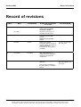
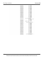
Record of revisions
Record of revisions
Index
A
Date
16/06/99
Compiled by
JP. Huriaux
06/15/2001
B
14/05/03
Origin and description
of revision
Original MGPI document # 1600140, based upon MGPSA
document # 117905AA
Revised pages
First edition
Revised to reflect changes for
Dosimass / Dosinet Versions
J. Perez
Application of the new MGPI
template
All
Updated according to DEV
N°12511
C
15/07/03
J.Perez
DEVS 13420, added
information relative to the new
readers LDM220 and LDM210
and complementary
information for the installation
procedure.
D
13/11/2003
D. Chatron
DEV 13516 /REV 6614,
modification of the installation
screens for the dosimeter
configuration.
A
04/12/03
Apply new numbering
sequence.
First issue and translation of
the user guide N° 117905D to
French.
IV
p1, p3, p, p5, p10, p42,
p61, p95, p101
§1.4.2, §2.2.3, §2.2.4
§2.3.5 §5.2 §Note :13.2
§ 13.3 §14
128110A
Publication, traduction et reproduction totales ou partielles de ce document sont rigoureusement interdites, sauf autorisation écrite de nos services.
The publication, translation or reproduction, either partly or wholly, of this document is not allowed without our written consent. Format 112175C
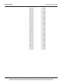
Table of Contents
Dosimass DM
Table of Contents
1.
OVERVIEW .....................................................................................................................1
1.1
1.2
1.3
1.4
2.
Synopsis.......................................................................................................................... 1
Reference Documents..................................................................................................... 1
Conventions .................................................................................................................... 2
1.3.1 Operating System .............................................................................................. 2
1.3.2 Screen Captures ................................................................................................ 2
1.3.3 Function Selection via Menu .............................................................................. 2
1.3.4 Terminology ....................................................................................................... 3
1.3.5 Advisories, Reminders and Notes ...................................................................... 3
Software Description ....................................................................................................... 3
1.4.1 Features ............................................................................................................. 3
1.4.2 Compatibility with previous generation products ................................................ 4
1.4.3 Compatibility with DMC_MANAGER, DMC_USER and DMC_HISTO Software 4
1.4.4 Configurations .................................................................................................... 5
MASS STORAGE (HARD INSTALLATION AND START-UP) .......................................7
2.1
2.2
2.3
2.4
Required Hardware Configuration................................................................................... 7
Hardware Installation ...................................................................................................... 8
2.2.1 Hardware Configuration with an LDM 2000 ....................................................... 8
2.2.2 Hardware Configuration with an LDM-101 ......................................................... 9
2.2.3 Device Configuration with LDM210 .................................................................. 10
2.2.4 Device Configuration with LDM220 .................................................................. 10
2.2.5 Installation of the TCP/IP Protocol ................................................................... 10
Installation of the Software ............................................................................................ 11
2.3.1 Installation Start-up .......................................................................................... 11
2.3.2 Language Choice ............................................................................................. 12
2.3.3 Choice of Installation Folder Location .............................................................. 14
2.3.4 Installation Wrap-up ......................................................................................... 16
2.3.5 Registration of the Serial Number .................................................................... 17
2.3.6 Selection of the Software Modules................................................................... 18
2.3.7 Creation of a Program Folder........................................................................... 19
2.3.8 Selection of the Type of Dosimeter Reader ..................................................... 20
2.3.9 Installing the TCP/IP Protocol during the Installation of the DOSIMASS
Dosimeter Software....................................................................................................... 21
2.3.10 Completing the Installation Procedure ............................................................. 22
2.3.11 Installation Complete........................................................................................ 23
2.3.12 2.3.11 Access to the DOSIMASS Software Modules ....................................... 24
Start-up of the DOSIMASS Dosimeter Software ........................................................... 24
2.4.1 Start-up using Windows Desktop ..................................................................... 25
2.4.2 Start-up using the Windows «Start» Menu Bar ................................................ 27
2.4.3 Startup using Windows Desktop for use with the LDM 210/220 ...................... 28
2.4.4 Startup using Windows Desktop for use with the LDM 2000 or the LDM 101
Reader
........................................................................................................... 29
128110A
Publication, traduction et reproduction totales ou partielles de ce document sont rigoureusement interdites, sauf autorisation écrite de nos services.
The publication, translation or reproduction, either partly or wholly, of this document is not allowed without our written consent. Format 112175C
V
Dosimass DM
2.5
3.
3.3
3.4
3.5
4.4
4.5
4.6
4.7
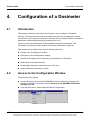
Introduction ................................................................................................................... 51
Access to the Configuration Window............................................................................. 51
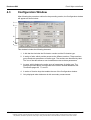
Configuration Window ................................................................................................... 53
4.3.1 Tabs
........................................................................................................... 54
4.3.2 Parameter Zone ............................................................................................... 55
4.3.3 Function Keys .................................................................................................. 57
Display of Dosimeter Parameters.................................................................................. 58
Modification of Dosimeter Parameters .......................................................................... 58
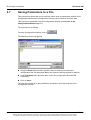
Downloading Parameters from a File ............................................................................ 59
Saving Parameters to a File .......................................................................................... 60
DOSIMETER PARAMETERS .......................................................................................61
5.1
5.2
VI
Introduction ................................................................................................................... 33
Access Levels ............................................................................................................... 33
3.2.1 Operator Level ................................................................................................. 33
3.2.2 Supervisor Level .............................................................................................. 34
3.2.3 Administrator Level .......................................................................................... 34
3.2.4 Manufacturer (Factory) Level ........................................................................... 35
Main Screen .................................................................................................................. 35
Functions Accessible from the Menu Bar...................................................................... 36
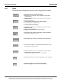
3.4.1 File Menu Ctrl+Q .............................................................................................. 36
3.4.2 Administration Menu ........................................................................................ 37
3.4.3 Set Up Menu .................................................................................................... 42
3.4.4 Dosimeter Menu ............................................................................................... 43
3.4.5 Tools Menu ...................................................................................................... 45
3.4.6 Help Menu........................................................................................................ 46
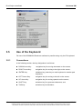
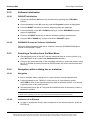
Use of the Keyboard...................................................................................................... 48
3.5.1 Conventions ..................................................................................................... 48
3.5.2 Software Initialization ....................................................................................... 49
3.5.3 Selecting a Function from the Main Menu........................................................ 49
3.5.4 Navigation within a dialog box or a window...................................................... 49
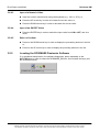
3.5.5 Locating the DOSIMASS Dosimeter Software ................................................. 50
CONFIGURATION OF A DOSIMETER.........................................................................51
4.1
4.2
4.3
5.
Shutdown of the Software Modules............................................................................... 31
2.5.1 Shutdown of the DOSIMASS Dosimeter Software Module .............................. 31
2.5.2 Shutdown of the DOSINET Software Module .................................................. 31
GENERAL OVERVIEW.................................................................................................33
3.1
3.2
4.
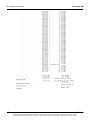
Table of Contents
Introduction ................................................................................................................... 61
DMC 2000 with LDM 2000, LDM220 or LDM210.......................................................... 61
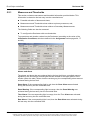
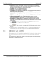
5.2.1 Measures and Thresholds................................................................................ 62
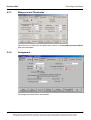
5.2.2 Assignment ...................................................................................................... 64
5.2.3 Status 66
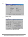
5.2.4 Operating Parameters ...................................................................................... 67
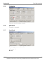
5.2.5 Calibrations ...................................................................................................... 69
5.2.6 Sub-zones ........................................................................................................ 70
5.2.7 User Block........................................................................................................ 71
5.2.8 System ........................................................................................................... 72
5.2.9 Factory ........................................................................................................... 75
128110A
Publication, traduction et reproduction totales ou partielles de ce document sont rigoureusement interdites, sauf autorisation écrite de nos services.
The publication, translation or reproduction, either partly or wholly, of this document is not allowed without our written consent. Format 112175C
Table of Contents
5.3
5.4
Dosimass DM
DMC 2000 with LDM-101 .............................................................................................. 76
5.3.1 Measures and Thresholds................................................................................ 77
5.3.2 Assignment ...................................................................................................... 77
5.3.3 Status 78
5.3.4 Operating Parameters ...................................................................................... 78
5.3.5 Calibrations ...................................................................................................... 79
5.3.6 Sub-Zones........................................................................................................ 79
5.3.7 User Block........................................................................................................ 79
5.3.8 System ........................................................................................................... 80
5.3.9 Factory 80
DMC-100, DMC-90, DM-9X with LDM-101 ................................................................... 81
5.4.1 Measures and Thresholds................................................................................ 81
5.4.2 Assignment ...................................................................................................... 82
5.4.3 Status ........................................................................................................... 82
5.4.4 Operating Parameters ...................................................................................... 83
5.4.5 Calibrations ...................................................................................................... 84
5.4.6 Sub-Zones........................................................................................................ 84
5.4.7 User Block........................................................................................................ 84
5.4.8 System ........................................................................................................... 85
5.4.9 Factory ........................................................................................................... 86
6.
MULTIPLE CONFIGURATION OF THE DOSIMETERS ...............................................87
7.
PASSAGE INTO A CONTROLLED AREA (RCA) ........................................................89
7.1
7.2
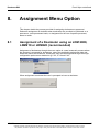
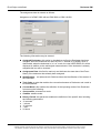
8.
ASSIGNMENT MENU OPTION.....................................................................................95
8.1
8.2
8.3
9.
Entry into a Controlled Area .......................................................................................... 89
Exit from a Controlled Area ........................................................................................... 91
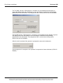
Assignment of a Dosimeter using an LDM 2000, LDM210 or LDM220 (recommended)95
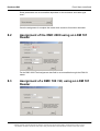
Assignment of the DMC 2000 using an LDM 101 Reader ............................................ 97
Assignment of a DMC 100 / 90, using an LDM 101 Reader ......................................... 97
OPERATION OF THE EVENTS HISTORY MENU OPTION .........................................99
9.1
9.2
9.3
9.4
9.5
9.6
9.7
9.8
Introduction ................................................................................................................... 99
Important Definitions ..................................................................................................... 99
9.2.1 Events History .................................................................................................. 99
9.2.2 Current Events History ..................................................................................... 99
9.2.3 Closure of an Events History.......................................................................... 100
9.2.4 Number of Events History .............................................................................. 100
9.2.5 Events History Saturation............................................................................... 100
9.2.6 Events History Period..................................................................................... 100
9.2.7 Dose Increment .............................................................................................. 100
Access to the Events History Function........................................................................ 101
Events History ............................................................................................................. 101
Function Keys.............................................................................................................. 102
Reading an Events History.......................................................................................... 103
9.6.1 From a Dosimeter: ......................................................................................... 103
9.6.2 From a File: .................................................................................................... 103
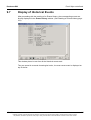
Display of Historical Events......................................................................................... 105
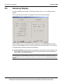
Summary Display ........................................................................................................ 106
128110A
Publication, traduction et reproduction totales ou partielles de ce document sont rigoureusement interdites, sauf autorisation écrite de nos services.
The publication, translation or reproduction, either partly or wholly, of this document is not allowed without our written consent. Format 112175C
VII
Dosimass DM
9.9
9.10
9.11
9.12
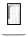
Table of Contents
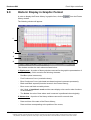
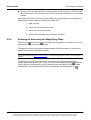
Historic Display in Graphic Format.............................................................................. 107
9.9.1 Navigation of the Cursor and Pointer ............................................................. 108
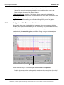
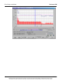
9.9.2 Zooming an Area using the Magnifying Glass................................................ 109
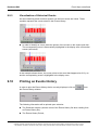
9.9.3 Visualization of Historical Events ................................................................... 111
Printing an Events History ........................................................................................... 111
Exporting a history file ................................................................................................. 112
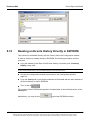
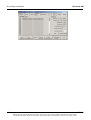
Reading an Events History Directly in E2PROM......................................................... 113
10. DIAGNOSTICS............................................................................................................115
10.1
10.2
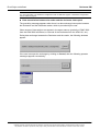
Operator Messages..................................................................................................... 115
10.1.1 Common Examples ........................................................................................ 115
10.1.2 List of Operator Messages ............................................................................. 117
Keyboard Shortcuts/Hotkeys....................................................................................... 121
11. APPENDIX 1: CUSTOMIZED SOFTWARE CONFIGURATIONS...............................123
11.1
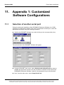
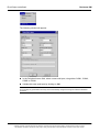
Selection of another serial port.................................................................................... 123
12. APPENDIX 2: INSTALLATION OF THE TCP/IP PROTOCOL ...................................125
12.1
12.2
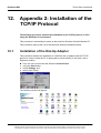
Installation of the Dial-Up Adapter............................................................................... 125
Installation of the Windows communication module.................................................... 129
13. APPENDIX 3 : EVENTS HISTORY SUPPLEMENTARY INFORMATION ..................133
13.1
13.2
13.3
List of Events in an Events History.............................................................................. 133
13.1.1 Alarms, Warnings and Measurement Variances ............................................ 133
13.1.2 Events and DM faults ..................................................................................... 134
13.1.3 Follow-up events ............................................................................................ 134
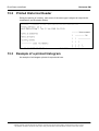
Printed Historical Header ............................................................................................ 136
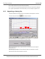
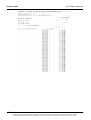
Example of a printed histogram................................................................................... 136
14. GLOSSARY.................................................................................................................143
VIII
128110A
Publication, traduction et reproduction totales ou partielles de ce document sont rigoureusement interdites, sauf autorisation écrite de nos services.
The publication, translation or reproduction, either partly or wholly, of this document is not allowed without our written consent. Format 112175C
Dosimass DM
Error! Style not defined.
1.
Overview
1.1
Synopsis
This Manual provides users with the information required to ensure effective use of the
DOSIMASS Dosimeter software. The software has been designed for use with the DMC
2000 dosimeter and the LDM 2000, and the LDM 210/220 Dosimeter readers, operating
under a Windows PC-based computing environment.
This Manual also provides all of the information necessary to use this software with the
previous generation of products (DMC-100 / DMC-90 dosimeters and LDM-101 / LDM91 readers).
For information regarding the use of this software under other hardware platforms or
operating environments, please contact MGP Instruments.
For more information concerning the Dosimeter and Dosimeter readers, please consult
the designated User’s Manuals (see Reference Documents noted below).
Note :
This document is designed for users who possess a good working knowledge of the computing environment
on which the DOSIMASS Dosimeter software has been installed. This includes general working knowledge
of functions such as the use of a mouse, access to menus, and file system management (opening, saving
and closing files). The user should consult the appropriate User Manuals for information on the respective
operating systems.
1.2
Reference Documents
For information regarding equipment compatible with the DOSIMASS Dosimeter
software, refer to the User’s Manuals listed below:
DMC 2000 Dosimeter User’s Manual
LDM 2000 Reader User’s Manual
DMC-100 Dosimeter User’s Manual
DMC_User Software User’s Manual
Dosiview Software User’s Manual
DMC_Histo Software User’s Manual
LDM-91 Reader User’s Manual
128110A
Publication, traduction et reproduction totales ou partielles de ce document sont rigoureusement interdites, sauf autorisation écrite de nos services.
The publication, translation or reproduction, either partly or wholly, of this document is not allowed without our written consent. Format 112175C
1
Error! Style not defined.
Dosimass DM
LDM-101 Reader User’s Manual
LDM210 – LDM220 reader user's manual
1.3
Conventions
Symbols " " and " ":
These symbols are used for the descriptions and details:
The symbol " " corresponds to the first level of detail.
The symbol " " corresponds to the second level of detail.
For legibility purpose these symbols are aligned vertically.
1.3.1
Operating System
For reasons of convention, all references to the Microsoft Windows version (95, 98 or
NT) of the Operating System will only be used if a feature / is specific to that operating
system.
1.3.2
Screen Captures
In order to facilitate the use of the DOSIMASS Dosimeter software, this Manual contains
screen captures.
The majority of screen captures present in this Manual were generated from the
"Windows 95®" Operating System environment. Minor differences may appear on the
screen captures that correspond to other environments.
Note :
Unless otherwise specified, the screen copies presented in this Manual correspond to the highest level of
user access. For further information on the management of access levels, consult the section entitled
"Access Levels," page 31.
1.3.3
Function Selection via Menu
In order to increase the readability of this Manual, selecting a function from the Menu of
an application operating under Windows will be indicated in the following manner:
From the main menu, select Menu_Function, Menu_Sub_Function,
Supplementary_Function, Supplementary_Sub _Function, etc.
For example:
«In order to print a document, select «File /Print.»
2
128110A
Publication, traduction et reproduction totales ou partielles de ce document sont rigoureusement interdites, sauf autorisation écrite de nos services.
The publication, translation or reproduction, either partly or wholly, of this document is not allowed without our written consent. Format 112175C
Dosimass DM
1.3.4
Error! Style not defined.
Terminology
This Manual employs a number of terms that are specific to the field of Dosimetry. In
order to avoid making the Manual overly complex, most of these terms are explained in
detail in the Glossary, which is located at the end of the document.
1.3.5
Advisories, Reminders and Notes
Throughout this Manual, the user will find additions to the text entitled Advisory,
Reminder or Note. These additions are used for the following:
Advisory:
the advice contained in these sections will aid the user in working more efficiently. Shortcuts are provided wherever
possible, as well as time saving tips
Reminder:
the reminders review information already provided elsewhere in the Manual and will help the user avoid redundant
searches.
Note :
These remarks highlight important points, exceptions and specific information.
1.4
Software Description
The DOSIMASS Dosimeter software:
DOSIMETER MAINTENANCE AND SET-UP SOFTWARE
…is software specifically adapted to the configuration and operation of the DMC2000
Dosimeter family.
The DOSIMASS Dosimeter software is delivered with a CD-ROM that contains:
DOSIMASS (DMC and LDM):
DOSINET:
# 723
# 734
This software is compatible with numerous platforms (PC-based, workstations) and
Operating Systems (Windows 95/98, Windows 2000, Windows XP, Windows NT, Advanced Server and Workstation).
1.4.1
Features
The DOSIMASS Dosimeter software offers the following features:
Individual configuration of the Dosimeters; including:
Readout and display of the actual Dosimeter parameters;
Modification of the Dosimeter parameters;
Downloading of the Dosimeter parameters from a file; and,
Saving the Dosimeter parameters into a file.
Multiple configuration of the Dosimeters in lots;
128110A
Publication, traduction et reproduction totales ou partielles de ce document sont rigoureusement interdites, sauf autorisation écrite de nos services.
The publication, translation or reproduction, either partly or wholly, of this document is not allowed without our written consent. Format 112175C
3
Error! Style not defined.
Dosimass DM
Simplified Controlled Area entrance/exit functions;
Troubleshooting Diagnostics and Dosimeter Repair;
Readout of Dosimeter event history.
1.4.2
Compatibility with previous generation products
The dosimetry DOSIMASS software is compatible with the following previous generation
products:
Dosimeter models DMC100, DMC90, DM9X
Dosimeter reader models LDM101, LDM91
Additionally it provides all the functionalities of previous generation programs (see
below).
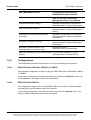
1.4.3
Compatibility with DMC_MANAGER, DMC_USER and
DMC_HISTO Software
The features of the previous generation software are supported by the current version of
the DOSIMASS Dosimeter Software.
DMC_MANAGER Features
Corresponding Features of the
DOSIMASS Dosimeter Software
Dosimeter parameter changing or loading
Individual configuration of a Dosimeter
(Dosimeter Menu / Single Configuration)
Operation, display of the Events History
Events History Operation Feature
(Dosimeter Menu / Events History)
Initialization of a Dosimeter from a
Command file
Individual Configuration of a Dosimeter
Modification of the Dosimeter calibration
coefficients
Individual Configuration of a Dosimeter
(Dosimeter Menu / Single Configuration)
(Dosimeter Menu / Single Configuration
/ Calibrations)
Readout of a Dosimeter EEPROM
Individual Configuration of a Dosimeter
(Dosimeter Menu / Single Configuration /
Factory)
4
Dosimeter Transition IN/OUT of a
Controlled Area
Enter/Exit Function
(Dosimeter Menu / Entrance / Exit)
Read and write of messages in Manual
Mode with the Dosimeter
Individual Configuration of a Dosimeter
(Dosimeter Menu / Single Configuration)
128110A
Publication, traduction et reproduction totales ou partielles de ce document sont rigoureusement interdites, sauf autorisation écrite de nos services.
The publication, translation or reproduction, either partly or wholly, of this document is not allowed without our written consent. Format 112175C
Dosimass DM
Error! Style not defined.
DMC_MANAGER Features
Corresponding Features of the
DOSIMASS Dosimeter Software
Note: for the user, the Message
Management feature is transparent.
Dosimeter parameter change
Individual configuration of a Dosimeter
(Dosimeter Menu / Single Configuration)
Dosimeter readout (status)
Individual configuration of a Dosimeter
(Dosimeter Menu / Single Configuration /
Status)
Modification of the Dosimeter Efficiency
Coefficient
Individual Configuration of a Dosimeter
(Dosimeter Menu / Single Configuration/
Calibrations)
Dosimeter ‘Transition to Pause’
Individual Configuration of a Dosimeter
(Dosimeter Menu / Single Configuration/
Assignment)
Dosimeter Transition IN/OUT of a
Controlled Area in automatic mode
Enter/Exit Function
(Dosimeter Menu / Entrance/Exit)
Operation and Display of the Events History Events History Operation Function
(Dosimeter Menu / Events History)
Feature
1.4.4
Configurations
The DOSIMASS Dosimeter Software can be used in the following configurations:
1.4.4.1
DMC 2000 with LDM 2000, LDM210 or LDM220
This standard configuration consists of using the DMC 2000 with an LDM 2000, LDM210
or LDM220.
In this type of configuration, the data exchange is performed in «hands-free» mode. All
of the parameters of the DMC 2000 can be transmitted.
1.4.4.2
DMC 2000 with LDM-101
This configuration enables the use of the DMC 2000 with an LDM-101 Infra-red reader,
equipped with a specific adapter (DMC 2000 sleeve).
In this type of configuration, the data exchange is carried out in «infrared» mode. The
majority of DMC 2000 parameters can be transmitted.
128110A
Publication, traduction et reproduction totales ou partielles de ce document sont rigoureusement interdites, sauf autorisation écrite de nos services.
The publication, translation or reproduction, either partly or wholly, of this document is not allowed without our written consent. Format 112175C
5
Error! Style not defined.
1.4.4.3
Dosimass DM
DMC-100, DMC-90, DM9X with LDM-101
This configuration ensures total compatibility with these products.
In this configuration, the data exchange is conducted in «infrared» mode. The majority
of Dosimeter parameters can be transmitted.
1.4.4.4
DMC 2000, DMC-100, DMC-90, DM9X with LDM-91
These configurations require the use of an LDM-91 operating in «transparent» mode in
lieu of the LDM-101. Note that, in order for the LDM-91 reader to function in
«transparent» mode, it must be equipped with internal firmware version (example:
532B).
These configurations react exactly as the two previous configurations. As such, they are
not detailed in the pages that follow.
For additional information on the LDM-91 and its operation in «transparent» mode,
consult the User’s Manual.
6
128110A
Publication, traduction et reproduction totales ou partielles de ce document sont rigoureusement interdites, sauf autorisation écrite de nos services.
The publication, translation or reproduction, either partly or wholly, of this document is not allowed without our written consent. Format 112175C
Dosimass DM
2.
Error! Style not defined.
Mass storage (hard
Installation and Start-up)
The installation and commissioning of the DOSIMASS consists of the following
successive steps:
Install the hardware configuration (connect the PC to the Dosimeter reader);
Install the software onto a computer
Configure and establish the links between the PC and the Dosimeter reader.
2.1
Required Hardware Configuration
When using the DOSIMASS Dosimeter Software with a PC, the latter must possess a
minimum of the following::
INTEL Pentium 233MHz PC compatible
hard drive capacity >= 4Gbytes
Working memory RAM >= 128 Mega-bytes
1 available serial communication port configured for use with Microsoft Windows
(95, 98/ME, NT, 2000 or XP)
SVGA display 800 x 600 resolution
TCP/IP protocol for Windows
"Laser-jet" type printer
PC compatible mouse or pointing device
a Software pprogram CD-ROM, MGP Instruments Part Number 116949 contains the
following software modules:
DOSIMASS (DMC and LDM):
Number 723
DOSINET:
Number 734
To operate, the software is issued and requires a protection key to be installed in the
parallel port of the PC.
128110A
Publication, traduction et reproduction totales ou partielles de ce document sont rigoureusement interdites, sauf autorisation écrite de nos services.
The publication, translation or reproduction, either partly or wholly, of this document is not allowed without our written consent. Format 112175C
7
Error! Style not defined.
2.2
Dosimass DM
Hardware Installation
The hardware installation consists of physically connecting the PC to the Dosimeter
reader and then configuring and establishing the link between the two entities.
The following paragraphs will review the procedures relative to the installation of an
LDM 2000 and an LDM 101.
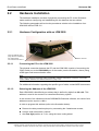
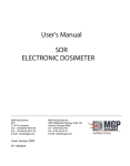
2.2.1
Hardware Configuration with an LDM 2000
Verify the address of the
plugs, which is indicated by
the coding wheels.
The value must be set at 1
2.2.1.1
RS232 / 485 Port
Connecting the PC to the LDM 2000
The physical connection between the PC and the LDM 2000 consists of connecting the
COM1 serial port to the RS232/485 port of the reader (see the illustration, above) using
a DB9 type serial communication cable.
Note :
When using a serial port other than COM1, a DOSINET software configuration is required. (Consult the
section entitled “Selection of a Different Serial Port,” page 123.)
For additional information regarding the specific type of cable, contact MGP Instruments.
2.2.1.2
Selecting the Address of the LDM 2000
Each LDM 2000 is identified by an address that is defined by digits from 00 to 99. This
address is used in the context of a centralized Dosimetry system.
In the context of the utilization with the DOSIMASS Dosimeter software, the value of this
address must be equal to <<01>>.
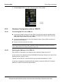
In order to program this address (refer to the illustration below):
Remove the side protection plaque by unscrewing the 2 attachment screws;
Using a small screwdriver, position:
the ones digit position to <<1>> using the lower coding wheel;
8
128110A
Publication, traduction et reproduction totales ou partielles de ce document sont rigoureusement interdites, sauf autorisation écrite de nos services.
The publication, translation or reproduction, either partly or wholly, of this document is not allowed without our written consent. Format 112175C
Dosimass DM
Error! Style not defined.
the tens digit position to <<0>> using the upper coding wheel.
tens digit
ones digit
2.2.2
Hardware Configuration with an LDM-101
2.2.2.1
Connecting the PC to the LDM-101
Connect the COM1 serial port to the LDM-101 serial port using the standard serial
cable supplied with the reader. This cable is equipped with a 9-pin male connector
(DB9) and a 9-pin female connector (DB9).
Connect the electrical cord to the outlet adapter using a 5-prong DIN connector at
the back of the LDM-101.
Plug the electrical cord into an outlet.
Note :
when using a serial port other than COM1, a DOSINET software configuration is required. (Consult the
section entitled “Selection of a Different Serial Port,” page 109.)
2.2.2.2
Selecting the Address of the LDM-101
Each LDM101 is identified by an address that is defined by digits from 0 to 7.
In the context of the utilization with the DOSIMASS Dosimeter software, the value of this
address must be equal to <<0>>.
Typically, each LDM-101 is delivered with a pre-programmed address of <<0>>.
In the case of problems associated with this address, consult the LDM-101 Technical
Manual or an MGP Instruments representative.
128110A
Publication, traduction et reproduction totales ou partielles de ce document sont rigoureusement interdites, sauf autorisation écrite de nos services.
The publication, translation or reproduction, either partly or wholly, of this document is not allowed without our written consent. Format 112175C
9
Error! Style not defined.
2.2.3
Device Configuration with LDM210
2.2.3.1
Connecting the PC to the LDM
Dosimass DM
Connect the PC COM1 serial port to the LDM 210 serial port using the supplied
standard 9 pin DB9-M/F cable.
Connect the power cord located in the back of the LDM.
Connect the power unit to the AC supply.
Note : In case another serial port is used, it would be necessary to change the DOSIMASS configuration
(see Selection of another serial port in page 123).
2.2.3.2
Select the address of the LDM
All LDM210 readers are identified by address 1.
In DOSIMASS, the user setting for this address should be set to « 1 ».
2.2.4
Device Configuration with LDM220
2.2.4.1
Connecting the PC to the LDM
The USB driver must be installed prior to operation. Please refer to the LDM 210/220
user manual.
Connect the cable provided to the USB port of the PC.
2.2.4.2
Select the address of the LDM
All LDM220 readers are identified with address 1.
In DOSIMASS, the user setting for this address should be set to « 1 ».
2.2.5
Installation of the TCP/IP Protocol
The TCP/IP Protocol must be installed on the PC before any other operations can be
performed using the DOSIMASS Dosimeter software.
When using a PC equipped with a LAN network card, or an existing INTERNET modem
access, this protocol is already installed.
If TCP/IP is not installed, the procedure to follow for the installation of this protocol is
reviewed in the section entitled "Appendix 2: Installation of the TCP/IP Protocol" page
125
10
128110A
Publication, traduction et reproduction totales ou partielles de ce document sont rigoureusement interdites, sauf autorisation écrite de nos services.
The publication, translation or reproduction, either partly or wholly, of this document is not allowed without our written consent. Format 112175C
Dosimass DM
2.3
Error! Style not defined.
Installation of the Software
The DOSIMASS Dosimeter software is delivered with a CD-ROM that contains the
DOSIMASS reader and DOSINET Software.
Note : During the installation of DOSIMASS DM it is necessary to install DOSINET. The installation of
DOSIMASS reader is optional.
The installation procedure consists of inserting and executing the installation program
« setup.exe » into the reader and following the directives issued in the following
sections.
Once the installation is finished, the array of installed software modules is accessible in
several ways:
Using the icons placed on the file located on the desktop;
Using the Windows « Start » menu; and / or
Using Windows « Explorer » to select the executable files placed in the installation
directories.
Note :
Using Windows « Explorer » to select the executable files placed in the installation directories
Each installation is valid for:
- A specific type of Dosimeter Reader (LDM 2000 or LDM-101); and
- A specific language used (French or English)
All subsequent modifications (changing the type of Reader or the language used) typically requires a new
installation.
If the use of the DOSIMASS Dosimeter software is desired with two different types of readers, then it is
recommended that the application be installed twice and the installer must specify two different installation
directories.
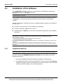
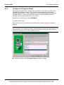
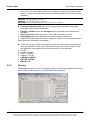
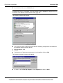
2.3.1
Installation Start-up
Advisory:
before beginning the installation procedure, the user is advised to quit all other applications in progress.
In order to install the DOSIMASS Dosimeter software the user should execute the
following instructions:
1. Insert the DOSIMASS Dosimeter Software Installation CD-ROM; and,
2. Using Windows Explorer (consult the illustration, below), execute the setup.exe
installation program, which is accessible from the main directory of the CD-ROM
reader, by double clicking on the corresponding file.
128110A
Publication, traduction et reproduction totales ou partielles de ce document sont rigoureusement interdites, sauf autorisation écrite de nos services.
The publication, translation or reproduction, either partly or wholly, of this document is not allowed without our written consent. Format 112175C
11
Error! Style not defined.
Dosimass DM
The following window is displayed:
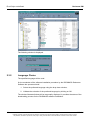
2.3.2
Language Choice
The specified language will be used:
for the remainder of the software installation procedure by the DOSIMASS Dosimeter
Software the operator should:
1. Select the preferred language using the drop down window;
2. Validate the selection of the preferred language by clicking on OK.
The window illustrated below will be temporarily displayed. It provides the status of the
downloading process for the DOSIMASS software installation.
12
128110A
Publication, traduction et reproduction totales ou partielles de ce document sont rigoureusement interdites, sauf autorisation écrite de nos services.
The publication, translation or reproduction, either partly or wholly, of this document is not allowed without our written consent. Format 112175C
Dosimass DM
Error! Style not defined.
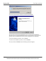
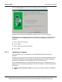
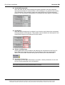
As soon as the download is complete, the window will disappear.
If the user did not shut down all applications prior to commencing the installation
procedure, then it is recommended that the user do so at this time. If the user exits at
this point, then the installation procedure must be reinitiated from the beginning.
To quit the installation procedure, click on Cancel;
To continue the installation procedure, click on Continue.
If the user clicks on Continue, then the following window will appear:
128110A
Publication, traduction et reproduction totales ou partielles de ce document sont rigoureusement interdites, sauf autorisation écrite de nos services.
The publication, translation or reproduction, either partly or wholly, of this document is not allowed without our written consent. Format 112175C
13
Error! Style not defined.
Dosimass DM
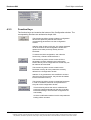
Note :
during the installation procedure, numerous windows that contain a <<back>> button will appear. This
option allows the user to return to the previous window and modify the parameters or cancel the parameter
modifications that were initially selected.
Click on Yes to accept the terms of the contract.
The following window appears
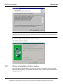
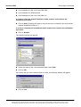
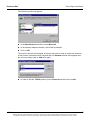
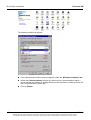
2.3.3
Choice of Installation Folder Location
Using the window pictured above, the user can specify an installation folder other than
that proposed as default. This possibility allows the user to conduct several installations
using the same PC:
14
128110A
Publication, traduction et reproduction totales ou partielles de ce document sont rigoureusement interdites, sauf autorisation écrite de nos services.
The publication, translation or reproduction, either partly or wholly, of this document is not allowed without our written consent. Format 112175C
Dosimass DM
Error! Style not defined.
One installation for the use of the LDM 2000
One installation for LDM-210/220
One installation for the use of the LDM-101
In order to select the default installation folder location and continue the
installation procedure:
Click on Next. (Subsequent steps in the procedure are reviewed in the next section,
entitled "Installation Wrap-up.")
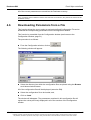
In order to customize the installation folder location and continue the installation
procedure:
Click on Browse.
The following window will appear:
Select the name of the new installation folder under Path.
Click on OK.
If the folder that you have selected does not exist, the following window will appear:
Click on Yes
128110A
Publication, traduction et reproduction totales ou partielles de ce document sont rigoureusement interdites, sauf autorisation écrite de nos services.
The publication, translation or reproduction, either partly or wholly, of this document is not allowed without our written consent. Format 112175C
15
Error! Style not defined.
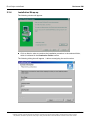
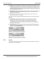
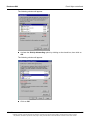
2.3.4
Dosimass DM
Installation Wrap-up
The following window will appear:
Click on Next in order to continue the installation procedure in the selected folder,
which is indicated in the Destination Folder section.
The following dialog box will appear. It allows reassigning the serial number.
16
128110A
Publication, traduction et reproduction totales ou partielles de ce document sont rigoureusement interdites, sauf autorisation écrite de nos services.
The publication, translation or reproduction, either partly or wholly, of this document is not allowed without our written consent. Format 112175C
Dosimass DM
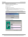
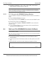
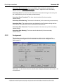
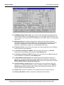
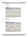
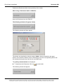
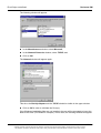
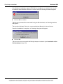
2.3.5
Error! Style not defined.
Registration of the Serial Number
This operation is necessary for the software to operate.
The following fields MUST be filled:
Name: user name,
Company: name of the company,
Serial N°: serial number provided with the software CD-ROM and the key. This
number is mandatory before the software can function.
Fill all the fields mentioned in the user license (must respect upper and lower case
characters.)
After entering all the information in the required fields, click on Continue.
Note :
If there is no user license, any serial number can be used (i.e.: « 012345 »), Dosimass_DM will work
normally but it will display the following message on start up:
The following window will appear:
128110A
Publication, traduction et reproduction totales ou partielles de ce document sont rigoureusement interdites, sauf autorisation écrite de nos services.
The publication, translation or reproduction, either partly or wholly, of this document is not allowed without our written consent. Format 112175C
17
Error! Style not defined.
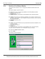
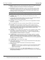
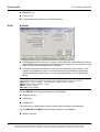
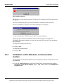
2.3.6
Dosimass DM
Selection of the Software Modules
The window above allows the user to designate the software modules that must be
installed.
Each option enables a specific selection:
Typical: This option mandates the installation of all of the software modules.
DOSIMASS Dosimeter; and,
DOSINET; and,
DOSIMASS Reader (Please Note: not all installation CD’s contain this option)
Compact: This option only enables the installation of the software modules that are
necessary for the operation of the DOSIMASS Dosimeter Software, while minimizing
the required disk space.
DOSIMASS Dosimeter; and,
DOSINET.
Custom: This option allows the user to proceed with the selective installation of one
or several modules.
DOSIMASS Dosimeter; or,
DOSINET; or,
DOSIMASS Reader (Please Note: not all installation CD’s contain this option)
To continue with the installation of the DOSIMASS Dosimeter Software:
Select the compact installation option;
Click on Next.
The following window will appear:
18
128110A
Publication, traduction et reproduction totales ou partielles de ce document sont rigoureusement interdites, sauf autorisation écrite de nos services.
The publication, translation or reproduction, either partly or wholly, of this document is not allowed without our written consent. Format 112175C
Dosimass DM
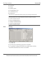
2.3.7
Error! Style not defined.
Creation of a Program Folder
The window displayed above enables the customization of the start-up folder for the
DOSIMASS Dosimeter Software. This folder will automatically be placed in the
Windows program folder. It will contain all of the icons corresponding to the different
software modules. These icons will allow the user to start the different software
modules using a simple double click of the mouse.
By default, the folder will be called DOSIMASS.
To apply another name:
Select the new name in the section entitled Program Folders (consult the following
window).
Note :
the user can also select an existing program file. This allows the user to regroup all of the software from the
same manufacturer. The user must simply highlight the folder name in the Existing Folder section and
double click on the folder name in order to activate the selection.
Validate the name of the Program Folder by clicking on Next.
128110A
Publication, traduction et reproduction totales ou partielles de ce document sont rigoureusement interdites, sauf autorisation écrite de nos services.
The publication, translation or reproduction, either partly or wholly, of this document is not allowed without our written consent. Format 112175C
19
Error! Style not defined.
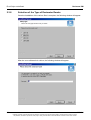
2.3.8
Dosimass DM
Selection of the Type of Dosimeter Reader
Once the installation of the various files is complete, the following window will appear:
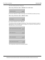
After the user validates their choice, the following window will appear
:
20
128110A
Publication, traduction et reproduction totales ou partielles de ce document sont rigoureusement interdites, sauf autorisation écrite de nos services.
The publication, translation or reproduction, either partly or wholly, of this document is not allowed without our written consent. Format 112175C
Dosimass DM
Error! Style not defined.
After the user validates their choice, the following window will appear:
2.3.9
Installing the TCP/IP Protocol during the Installation of the
DOSIMASS Dosimeter Software
The preceding window allows the user to install the TCP/IP Protocol.
The link between the PC and the Dosimeter reader uses this protocol (managed
transparently by the DOSINET module). If the PC is equipped with a LAN Network card,
this protocol is already installed.
To install the TCP/IP Protocol at this point:
Click on Yes.
For this option, follow the procedure that is provided in the Appendix 1: Customized
Software Configurations, in the Section entitled "Installation of the TCP/IP Protocol."
In order to terminate the installation and install the TCP/IP Protocol at another date:
Click on No.
In this case, a Readme.doc file will open automatically in the web browser (e.g., internet
explorer). This file contains supplementary information that is accessible directly from
the PC. It can be found in the installation directory that was previously selected.
This Readme.doc file can be printed from the open file (using the File / Print option via
the main Menu).
128110A
Publication, traduction et reproduction totales ou partielles de ce document sont rigoureusement interdites, sauf autorisation écrite de nos services.
The publication, translation or reproduction, either partly or wholly, of this document is not allowed without our written consent. Format 112175C
21
Error! Style not defined.
Dosimass DM
The installation of files will now begin.
Status windows will appear, providing a progress report on the downloading of the files
to the PC disk.
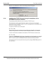
2.3.10
Completing the Installation Procedure
In order to complete the installation procedure, the Readme.doc file must be closed. If
this file is left open, no further operations can be performed.
From the main Menu of the Readme.doc application, select File / Exit.
Note :
if the Readme.doc application is no longer visible on the screen, then follow the instructions below in order
to make it reappear.
Press the Alt key on the keyboard and keep it pressed down; and,
Press several times on the Tab key in order to view the different application windows that function under
Windows. As soon as the icon that corresponds to the Readme.doc application appears, release the Alt
and Tab keys immediately.
22
128110A
Publication, traduction et reproduction totales ou partielles de ce document sont rigoureusement interdites, sauf autorisation écrite de nos services.
The publication, translation or reproduction, either partly or wholly, of this document is not allowed without our written consent. Format 112175C
Dosimass DM
Error! Style not defined.
Once the Readme.doc file is closed, the following window will appear:
In order to fully complete the installation procedure, the PC must be rebooted.
Nevertheless, if other applications must be installed, for example, the TCP/IP Protocol,
rebooting the PC can be performed once all of the other installation procedures are
complete.
In order to reboot the computer:
Click on Yes.
In order to delay rebooting the computer:
Click on No.
2.3.11
Installation Complete
After rebooting the PC, the installation of the DOSIMASS Dosimeter Software is
complete.
Generally, all of the parameters required for the operation of the DOSIMASS Dosimeter
and DOSINET Software are automatically configured during the software installation
procedure (configuration of the link between the PC and the reader).
If the constraints relative to the reader address and the choice of serial port were not
respected, then the following parameters must still be modified. Consult the procedures
listed below:
Address of the Dosimeter reader: see the section entitled "Hardware Installation,"
page 8.
128110A
Publication, traduction et reproduction totales ou partielles de ce document sont rigoureusement interdites, sauf autorisation écrite de nos services.
The publication, translation or reproduction, either partly or wholly, of this document is not allowed without our written consent. Format 112175C
23
Error! Style not defined.
Dosimass DM
Selection of a Serial Port: (COM1, COM2, COM3, COM4): see the section
entitled "Selection of another serial port," page 123.
Note :
Since all of the parameters required for the configuration of the DOSIMASS Dosimeter and DOSINET
software are accessible from the setup menu, it is highly recommended that NO manual modifications be
made to any files contained in the Installation directories.
2.3.12
2.3.11 Access to the DOSIMASS Software Modules
Once the installation is complete, the DOSIMASS Software modules are accessible as
follows:
Using the Windows Desktop environment:
The user simply double-clicks the DOSINET icon in order to start the DOSINET module.
Directly from the Folder in the Programs File:
The user selects Start / Programs / DOSIMASS / DOSINET in order to activate the
DOSINET module.
Using the Windows Explorer tool by direct selection of the executable files that
were placed in the installation folders.
2.4
Start-up of the DOSIMASS Dosimeter Software
Note : This section provides the procedure required in order to start-up the DOSIMASS Dosimeter software
once the installation is complete.
Note : Before initiating the DOSIMASS Dosimeter software start-up, the user must verify that the hardware
has been correctly installed, including:
Ensure that the connection cord between the PC and the Dosimeter reader is
correctly installed.
Switch the power button of the Dosimeter reader to the «On» position (for the LDM
101);
If using the LDM 2000, verify that the reader’s display panel appears as follows:
*
SLV
24
LCE
128110A
Publication, traduction et reproduction totales ou partielles de ce document sont rigoureusement interdites, sauf autorisation écrite de nos services.
The publication, translation or reproduction, either partly or wholly, of this document is not allowed without our written consent. Format 112175C
Dosimass DM
Error! Style not defined.
Note :
The elements of the displayed message have the following meaning:
SLV : The LDM 2000 reader is in «Slave » mode
LCE : The LDM 2000 reader is in « local » mode: it proceeds to access controls on local criteria and locally
stores the data on the viewed passages.
For further information regarding various reader displays, refer to the LDM 2000 User’s Manual.
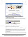
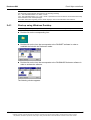
2.4.1
Start-up using Windows Desktop
Note : Using the start-up folder placed on the Desktop (entitled DOSIMASS by default)
Double click on the corresponding icon.
Double click on the icon that corresponds to the DOSINET software in order to
establish the link with the Dosimeter reader
Double click on the icon that corresponds to the DOSIMASS Dosimeter software in
order to activate the software.
The following window appears:
128110A
Publication, traduction et reproduction totales ou partielles de ce document sont rigoureusement interdites, sauf autorisation écrite de nos services.
The publication, translation or reproduction, either partly or wholly, of this document is not allowed without our written consent. Format 112175C
25
Error! Style not defined.
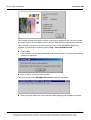
Dosimass DM
This window contains information relative to the license granted to the user, the number
and index number of the software version and the date that the software was published.
This information can also be found in the main menu of the DOSIMASS Dosimeter
software, by selecting the following option: Help / About DOSIMASS-DM.
Click on OK.
-
If the software has not been registered or the serial number is incorrect, the following
message is displayed:
Click on OK to access the main window
The main window of the DOSIMASS Dosimeter software will appear.
When using the LDM 2000, verify that the reader display panel appears as follows:
26
128110A
Publication, traduction et reproduction totales ou partielles de ce document sont rigoureusement interdites, sauf autorisation écrite de nos services.
The publication, translation or reproduction, either partly or wholly, of this document is not allowed without our written consent. Format 112175C
Dosimass DM
Error! Style not defined.
*
SLV
RMT
Note : The elements of the displayed message have the following meaning:
S L V : The LDM 2000 reader is in « Configuration » or « Slave » mode
RMT : The LDM 2000 reader is in « Remote » mode: it acts as a reader station controlled by
Dosimass Software
For further information regarding various reader displays, refer to the LDM 2000 User’s Manual.
If «SLV» or «RMT» is not displayed on the bottom, left-hand side of the display, then the
connection between the PC and the reader is not operational. If this is the case, then the
user must determine that the hardware has been installed correctly by verifying the
following:
The COM1 port of the PC is used for the LDM 2000 connection.
The physical address of the reader is set at <<1>>.
The cable is indeed a DB9 type serial communication cable.
For additional information, consult the section entitled "Hardware Configuration with an
LDM 2000," page 13.
2.4.2
Start-up using the Windows «Start» Menu Bar
The user can also start the DOSIMASS Dosimeter software using the Windows Start
menu bar (consult the illustration provided below):
1. Select Start / Programs / DOSIMASS / DOSINET in order to setup the connection
with the Dosimeter reader.
2. Select Start / Programs / DOSIMASS / DOSIMASS-DM in order to start the
DOSIMASS Dosimeter software.
128110A
Publication, traduction et reproduction totales ou partielles de ce document sont rigoureusement interdites, sauf autorisation écrite de nos services.
The publication, translation or reproduction, either partly or wholly, of this document is not allowed without our written consent. Format 112175C
27
Error! Style not defined.
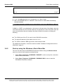
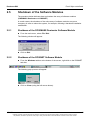
2.4.3
Dosimass DM
Startup using Windows Desktop for use with the LDM 210/220
Double click on the corresponding icon.
Double click on the icon that corresponds to the DOSIMASS Dosimeter software in
order to activate the software
The following window appears:
28
128110A
Publication, traduction et reproduction totales ou partielles de ce document sont rigoureusement interdites, sauf autorisation écrite de nos services.
The publication, translation or reproduction, either partly or wholly, of this document is not allowed without our written consent. Format 112175C
Dosimass DM
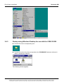
2.4.4
Error! Style not defined.
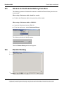
Startup using Windows Desktop for use with the LDM 2000 or
the LDM 101 Reader
Using the startup folder placed on the Desktop (entitled DOSIMASS by default)
Double click on the corresponding icon
Double click on the icon that corresponds to the DOSINET software in order to
establish the link with the Dosimeter reader
The following windowappears:
128110A
Publication, traduction et reproduction totales ou partielles de ce document sont rigoureusement interdites, sauf autorisation écrite de nos services.
The publication, translation or reproduction, either partly or wholly, of this document is not allowed without our written consent. Format 112175C
29
Error! Style not defined.
Dosimass DM
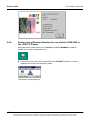
Double click on the icon that corresponds to the DOSIMASS Dosimeter software in
order to activate the software.
The following window appears:
30
128110A
Publication, traduction et reproduction totales ou partielles de ce document sont rigoureusement interdites, sauf autorisation écrite de nos services.
The publication, translation or reproduction, either partly or wholly, of this document is not allowed without our written consent. Format 112175C
Dosimass DM
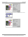
2.5
Error! Style not defined.
Shutdown of the Software Modules
The procedure below indicates how to shutdown the array of software modules
(DOSIMASS Dosimeter and DOSINET).
In certain cases, the shutdown of the entire array of software modules can prove
necessary in order to reboot the system, for example, following a hardware installation
modification.
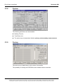
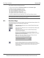
2.5.1
Shutdown of the DOSIMASS Dosimeter Software Module
From the main menu, select File / Exit.
The following window will appear:
Click on Exit.
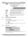
2.5.2
Shutdown of the DOSINET Software Module
From the Windows taskbar at the bottom of the screen, right-click on the DOSINET
task box.
The following pop-up menu will appear:
Click on Close (using the left mouse button).
128110A
Publication, traduction et reproduction totales ou partielles de ce document sont rigoureusement interdites, sauf autorisation écrite de nos services.
The publication, translation or reproduction, either partly or wholly, of this document is not allowed without our written consent. Format 112175C
31
Error! Style not defined.
Dosimass DM
Blank page
32
128110A
Publication, traduction et reproduction totales ou partielles de ce document sont rigoureusement interdites, sauf autorisation écrite de nos services.
The publication, translation or reproduction, either partly or wholly, of this document is not allowed without our written consent. Format 112175C
Dosimass DM
Error! Style not defined.
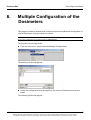
3.
General Overview
3.1
Introduction
This chapter is designed to facilitate access to the entire set of DOSIMASS Dosimeter
software functions.
As such, the following information will be presented:
Access levels to the different information;
Presentation of the main screen;
General description of all of the functions accessible from the menu; and,
Operating principles of the software using the keyboard.
3.2
Access Levels
Access to certain features is only permitted if the user possesses the required access
level authorization.
Selection of an access level can be carried out by providing the following information:
the user name; and,
the associated password.
The parameter default values for each access level are reviewed below.
Note :
Refer to section Administration Menu page 37 for adding, deleting or modifying users, passwords and
access level authority. Users are strongly encouraged to establish new passwords to prevent unauthorized
access to dosimeter parameters
While using the DOSIMASS Dosimeter software, the current access level appears
between brackets in the title bar of the main menu, except for that of the lowest access
level.
3.2.1
Operator Level
Note :
The Operator level is the default access level at the start-up of the DOSIMASS Dosimeters software.
128110A
Publication, traduction et reproduction totales ou partielles de ce document sont rigoureusement interdites, sauf autorisation écrite de nos services.
The publication, translation or reproduction, either partly or wholly, of this document is not allowed without our written consent. Format 112175C
33
Error! Style not defined.
Dosimass DM
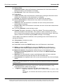
Other than the Log-Out and Account Management functions in the Administration
menu, the entire array of DOSIMASS Dosimeter software functions are accessible at the
Operator level with the following restrictions:
certain fields are not displayed
most of the displayed information cannot be modified.
Note :
The operator has access to the following parameters of the dosimeters:
Measurements and Thresholds (dose and rate settings only)
Assignment
Operating parameters
Refer to chapter "Dosimeter Parameters" page 61
3.2.1.1
Default Value of the Access Parameters
User Name: «operator»
Associated Password:
«operator»
Note :
if the system detects no action from the user (using either the keyboard or the mouse) for more than the
configured number of seconds then the DOSIMASS Dosimeter software automatically reverts to this default
access level
3.2.2
Supervisor Level
The entire array of functions of the DOSIMASS Dosimeter software, excluding the
Account Management function in the Administration menu, is accessible at the
Supervisor level, with the following restrictions:
Only the modification of the information relative to the internal operation parameters
(factory settings) of the Dosimeter is restricted.
3.2.2.1
Default Value of the Access Parameters
User Name: «supervisor»
Associated Password: «supervisor»
3.2.3
Administrator Level
This level provides access to all the functions excluding the Configuration and
Dosimeter menu functions.
This is the only level that is authorized to access the Account Management function
from the Administration menu. This function allows the user to manage the users and
their associated access authorization levels.
34
128110A
Publication, traduction et reproduction totales ou partielles de ce document sont rigoureusement interdites, sauf autorisation écrite de nos services.
The publication, translation or reproduction, either partly or wholly, of this document is not allowed without our written consent. Format 112175C
Dosimass DM
3.2.3.1
Error! Style not defined.
Default Value of the Access Parameters
User Name: «administrator»
Associated Password: «administrator»
3.2.4
Manufacturer (Factory) Level
The Manufacturer level of authorization has access to the entire array of the
DOSIMASS Dosimeter software functions excluding the Account Management function
in the Administration menu.
3.2.4.1
Default Value of the Access Parameters
User Name: «mgpi»
Associated Password: «mgpi»
Safety Alert: The Factory / Manufacturer level of authorization provides access
to the Manufacturing parameters of the Dosimeter, more specifically, the
calibration parameters. Only MGPI experts are permitted to modify these
parameters, and then only under controlled circumstances, since this could
cause a malfunction in the operation of the Dosimeters.
The User levels and functions may be summarized as follows:
3.3
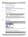
Main Screen
Note : The main screen of the DOSIMASS Dosimeter software is primarily accessible by activating the
corresponding icon (DOSIMASS-DM). For additional information concerning the start-up of the software,
see Start-up of the DOSIMASS Dosimeter Software, page 24.
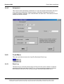
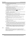
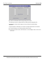
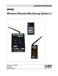
The main screen is comprised of a window that contains the following elements (see the
diagram, below):
A title bar (1), which contains the following information:
Current access level (2), in this case, Manufacturer level;
Note :
when the current access level is Operator, no access level information is displayed.
128110A
Publication, traduction et reproduction totales ou partielles de ce document sont rigoureusement interdites, sauf autorisation écrite de nos services.
The publication, translation or reproduction, either partly or wholly, of this document is not allowed without our written consent. Format 112175C
35
Error! Style not defined.
Dosimass DM
Name of the software (3), in this case DOSIMASS Dosimeter;
Date and time (4); and
Communication operating mode (5):
- «Hands-Free» in the case of an LDM 2000; and,
- «Infrared» in the case of an LDM-101 or an LDM-91.
A menu bar (6) which provides access to the array of available functions; and,
A blank area (7) that is designed to house the windows relative to the different
functions.
1
2
6
3.4
3
4
5
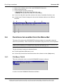
7
Functions Accessible from the Menu Bar
The array of functions of the DOSIMASS Dosimeter software is accessible using the
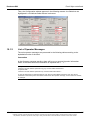
menu bar (see below). These functions are accessible using the mouse or the keyboard.
Note :
access to certain functions is only authorized if the user has the appropriate level of access defined by the
password (for more information, consult the section entitled Access Levels, page 33).
The list of primary functions is reiterated below:
Exit the application (File menu); and,
On-line help function and information about the software version (Help menu).
3.4.1
File Menu Ctrl+Q
This menu allows the user to exit the DOSIMASS Dosimeter software.
In order to exit the DOSIMASS Dosimeter software:
36
128110A
Publication, traduction et reproduction totales ou partielles de ce document sont rigoureusement interdites, sauf autorisation écrite de nos services.
The publication, translation or reproduction, either partly or wholly, of this document is not allowed without our written consent. Format 112175C
Dosimass DM
Error! Style not defined.
From the main menu, select File / Exit.
The following window will appear:
Click on Exit or press enter
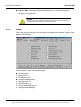
3.4.2
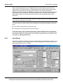
Administration Menu
This menu provides access to the functions that allow the user to manage the different
access levels.
For more information on the different access levels, see Access Levels, page 33
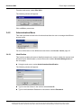
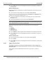
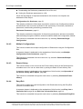
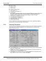
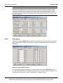
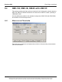
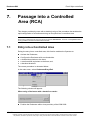
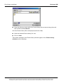
3.4.2.1
Identification
This function enables all users to identify themselves in order to obtain the access level
allocated by the Administrator (consult the section entitled Account Management on
the next page).
Using the main menu, select Administration/Identification.
The following window will appear:
Type in the User Name in the section entitled User ID.
Type in the Associated Password in the section entitled Password.
128110A
Publication, traduction et reproduction totales ou partielles de ce document sont rigoureusement interdites, sauf autorisation écrite de nos services.
The publication, translation or reproduction, either partly or wholly, of this document is not allowed without our written consent. Format 112175C
37
Error! Style not defined.
Dosimass DM
Note :
for security reasons, when typing the password entry, the alphanumeric characters are replaced by the *
symbol.
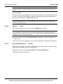
Click on OK.
The main screen will be displayed. The access level appears in the left-hand side of the
title bar. If no access level indication appears, then the selected access authorization
level is set at the default, or Operator access level.
Note :
in case of identification fault , (e.g., incorrect parameters), the current access level (e.g., Supervisor) is
accessible by clicking on Delete.
3.4.2.2
Log-Out
Ctrl+D
This function allows the user to return to the Operator access level.
Note :
if the system detects no action from the user (using either the keyboard or the mouse) for more than a
configurable delay (manufacturer configuration: 10 mn by default), then the DOSIMASS Dosimeter software
automatically reverts to this default access level.
Using the main menu, select Administration / Log-out, or use the keyboard hotkeys (Ctrl+D).
The main screen will be displayed. No access level indication will appear in the title bar.
3.4.2.3
Account Management
Ctrl+F4
This function allows the user to add, modify and delete different users and their access
levels and is accessible only to the Administrator.
Using the main menu, select Administration / Account Management,
The following window will appear:
38
128110A
Publication, traduction et reproduction totales ou partielles de ce document sont rigoureusement interdites, sauf autorisation écrite de nos services.
The publication, translation or reproduction, either partly or wholly, of this document is not allowed without our written consent. Format 112175C
Dosimass DM
Error! Style not defined.
Note :
regardless of the operation to be conducted (addition, modification, deletion of a user), begins by typing the
User Name in the section entitled User ID.
Add a New User
Type in the User Name in the section entitled User ID.
When the cursor moves into the following sections, Password 1 and Password 2, the
characters are automatically masked by the <<*>>symbol if the User ID already exists.
Type the password corresponding to the new user in the section entitled
Password 1; and,
Type the same password into the section entitled Password 2.
Note :
the two passwords must be identical, which allows the system to ensure that the password typed in the
section entitled Password 1 was input with no typographical errors. In case there is a discrepancy between
the two passwords, the user must input the two passwords again.
Select the corresponding access level in the drop-down menu, from among the
following:
Operator;
Supervisor;
Administrator; or,
MGP Instruments.
Click on Insert in order to register the new user account.
128110A
Publication, traduction et reproduction totales ou partielles de ce document sont rigoureusement interdites, sauf autorisation écrite de nos services.
The publication, translation or reproduction, either partly or wholly, of this document is not allowed without our written consent. Format 112175C
39
Error! Style not defined.
Dosimass DM
Click on Exit when the Account Management session is terminated, or continue on
to another task.
Modify an Existing User
This function allows the Administrator to modify the password or the access level of an
existing user.
Type in the name of the existing user in the section entitled User ID.
When the cursor moves into the following sections, Password 1 and Password 2, the
characters are automatically masked by the <<*>>.
Type the new password corresponding to the existing user in the section entitled
Password 1; and,
Type the same password into the section entitled Password 2.
Note :
the two passwords must be identical, which allows the system to ensure that the password typed in the
section entitled Password 1 was input with no typographical faults. In case there is a discrepancy between
the two passwords, the user must input the two passwords again.
Select the corresponding access level in the drop-down menu, from among the
following:
Operator;
Supervisor;
Administrator; or,
MGP Instruments.
Click on Modify in order to register these modifications to the existing user account.
Click on Exit when the Account Management session is terminated, or continue on
to another task.
Delete an Existing User
Type in the name of the existing user in the section entitled User ID.
Click on Delete.
Click on Exit when the Account Management session is terminated, or continue with
another task.
3.4.2.4
Login In Time Out Ctrl+t
The software uses a time out function for security purposes. If a user is logged in for
longer than a set time the system will log them off. This time out value is configurable by
the Administrator.
After logging in under the Administrator account the « log in time out » option is
available
40
128110A
Publication, traduction et reproduction totales ou partielles de ce document sont rigoureusement interdites, sauf autorisation écrite de nos services.
The publication, translation or reproduction, either partly or wholly, of this document is not allowed without our written consent. Format 112175C
Dosimass DM
Error! Style not defined.
Select the Login time out
The time out delay can be set up to 9999 seconds. The change will take effect after you
restart Dosimass
128110A
Publication, traduction et reproduction totales ou partielles de ce document sont rigoureusement interdites, sauf autorisation écrite de nos services.
The publication, translation or reproduction, either partly or wholly, of this document is not allowed without our written consent. Format 112175C
41
Error! Style not defined.
3.4.3
Dosimass DM
Set Up Menu
This menu provides access to the configuration functions of the DOSINET and
DOSIMASS Software modules.
3.4.3.1
Exchange
This function enables the user to configure the EXCHANGE, and more specifically, the
Dosimeter reader address.
From the main menu, select Configuration / Exchange.
The following window will appear:
Important note:
At the time of the installation, the entire array of EXCHANGE parameters is optimized. It is
highly recommended that NO modifications be made to the parameters that are accessible via
this window. The only exception to this recommendation concerns the Reader Address, and
this exception applies only in the event that the reader address does not correspond to the
recommended values (See the section "Selecting the Address of the LDM 2000 page 8 or
Selecting the Address of the LDM-101, page 9)
42
128110A
Publication, traduction et reproduction totales ou partielles de ce document sont rigoureusement interdites, sauf autorisation écrite de nos services.
The publication, translation or reproduction, either partly or wholly, of this document is not allowed without our written consent. Format 112175C
Dosimass DM
Error! Style not defined.
Input the actual physical address of the Dosimeter reader into the field entitled Plug
Number (Reader Address).
Click on OK in order to validate the input value.
3.4.3.2
General Parameters
This function allows the user to select the radiological units used in all the screens of the
DOSIMASS Dosimeter software, and Events History printing.
From the main menu, select Configuration / General Parameters.
The following window will appear:
Select the measurement display units from among the following:
mrem; or,
mSv; or,
cGy.
Validate the selection by clicking on OK.
3.4.4
Dosimeter Menu
This menu provides access to the primary functions of the DOSIMASS Dosimeter
Software.
3.4.4.1
Single Configuration
This function enables the individual configuration of each Dosimeter.
This process can be broken down into several basic functions:
Readout and Display of the entire parameter array of a Dosimeter;
Modification of the Dosimeter parameters;
128110A
Publication, traduction et reproduction totales ou partielles de ce document sont rigoureusement interdites, sauf autorisation écrite de nos services.
The publication, translation or reproduction, either partly or wholly, of this document is not allowed without our written consent. Format 112175C
43
Error! Style not defined.
Dosimass DM
Downloading the Dosimeter parameters from a file; and,
Saving the Dosimeter parameters to a file.
Given the high degree of importance attached to this function, two chapters are
dedicated to this subject.
Configuration of a Dosimeter, page 51
This chapter provides the information required for access to the Configuration window
and allows the user to become proficient in the entire array of functions (read/write of
parameters, downloading and saving parameter files).
Dosimeter Parameters, page 61
This chapter presents the description of the primary parameters, which are accessible
while browsing through the different sections contained within the Configuration window.
This function is accessible from the main menu, by selecting Dosimeter/Single
Configuration.
3.4.4.2
Multiple Configurations
This function enables the multiple configuration of Dosimeters using the Configuration
files.
A separate chapter is dedicated to the explanation of this function (see Multiple
Configuration of the Dosimeters, page 87).
This function is accessible from the main menu, by selection Dosimeter/Multiple
Configurations.
3.4.4.3
Events History
This function allows a user to recover the Events History stored in the Dosimeters for
immediate use or for use at a later date, by saving the data in Events History files.
A separate chapter is dedicated to the explanation of this function (see Operation of
the Events History Menu Option, page 99).
This function is accessible through the main menu, by selecting Dosimeter/Events
History.
3.4.4.4
Entry/Exit
This function enables the rapid configuration of all Dosimeters during the Entry/Exit
into/from a controlled area.
A separate chapter is dedicated to the explanation of this function (see Entry into a
Controlled Area, page 89 and Exit from a Controlled Area, page 91).
This function is accessible through the main menu, by selecting Dosimeter/Entry/Exit.
44
128110A
Publication, traduction et reproduction totales ou partielles de ce document sont rigoureusement interdites, sauf autorisation écrite de nos services.
The publication, translation or reproduction, either partly or wholly, of this document is not allowed without our written consent. Format 112175C
Dosimass DM
3.4.4.5
Error! Style not defined.
Assignment
This function allows allocating a dosimeter to a user with specific information about the
user saved to the dosimeter’s internal memory. Allocation information included: a
customized display message, user’s identification and task code. The historical interval
setting may also be defined.
3.4.5
Tools Menu
This menu provides access to the Log File (Dosimass Event Log).
3.4.5.1
Event Log
The Event Log is a file that continuously records all of the events relative to software
operations onto the hard disk of the PC (e.g., client connection messages, problems
encountered at the time of the connection setup, activation/deactivation, etc.).
128110A
Publication, traduction et reproduction totales ou partielles de ce document sont rigoureusement interdites, sauf autorisation écrite de nos services.
The publication, translation or reproduction, either partly or wholly, of this document is not allowed without our written consent. Format 112175C
45
Error! Style not defined.
Dosimass DM
These events are clearly identified by a label and are time/date-stamped. If the need
arises, these records will facilitate a joint problem analysis by the user and MGP
Instruments.
In order to access this function, activate the Tools/Event Log option from the main
menu.
This Event Log opens using a Windows application.
Note :
this Event Log is saved in a text file entitled "logfile.txt" and maintained under the Installation sub-directory
entitled "DOSIMASS_DM."
3.4.6
Help Menu
This menu provides access to the on-line help feature and provides information relative
to the DOSIMASS Dosimeter software.
3.4.6.1
Contents
This function provides access to the on-line help feature, if available.
46
128110A
Publication, traduction et reproduction totales ou partielles de ce document sont rigoureusement interdites, sauf autorisation écrite de nos services.
The publication, translation or reproduction, either partly or wholly, of this document is not allowed without our written consent. Format 112175C
Dosimass DM
3.4.6.2
Error! Style not defined.
Registration
This function allows entering the registration information of the software.
The following registration window will appear:
Enter the appropriate data in the three fields and validate by clicking on the Ok button.
Fill all the fields exactly as mentioned in the user license (must respect upper and lower
case characters for proper registration).
3.4.6.3
About DOSIMASS-DM
This function allows access to information concerning the DOSIMASS Dosimeter
software, including:
License granted to the user;
Number and version index of the Software; and,
Issuance date.
In order to access this function from the main menu select Help/About DOSIMASS-DM.
The following window will appear:
128110A
Publication, traduction et reproduction totales ou partielles de ce document sont rigoureusement interdites, sauf autorisation écrite de nos services.
The publication, translation or reproduction, either partly or wholly, of this document is not allowed without our written consent. Format 112175C
47
Error! Style not defined.
3.5
Dosimass DM
Use of the Keyboard
Full use of the DOSIMASS Dosimeter software is possible using only the PC keyboard.
3.5.1
Conventions
In the following section, the key designation is as follows:
48
DOWN Arrow Key:
navigation key for moving downward on the screen;
RIGHT Arrow Key:
navigation key for moving to the right on the screen;
ENTER Key:
validation key (enter key on main keyboard or number pad
keyboard);
LEFT Arrow Key:
navigation key for moving to the left on the screen;
UP Arrow Key:
navigation key for moving upwards on the screen;
SHIFT Key:
activation key for uppercase characters; and,
TAB Key:
activation key for tabulation.
128110A
Publication, traduction et reproduction totales ou partielles de ce document sont rigoureusement interdites, sauf autorisation écrite de nos services.
The publication, translation or reproduction, either partly or wholly, of this document is not allowed without our written consent. Format 112175C
Dosimass DM
Error! Style not defined.
3.5.2
Software Initialization
3.5.2.1
DOSINET Initialization
Access the Windows Start menu by simultaneously pressing the CTRL+ESC
buttons;
Press repeatedly on the UP arrow key until the Programs function is highlighted;
Press the RIGHT arrow key so that the program groups are displayed;
Press repeatedly on the UP or DOWN arrow keys until the DOSIMASS program
groups is highlighted;
Press on the RIGHT arrow key so that the software modules are displayed;
Press the UP or DOWN key in order to select the DOSINET option.
3.5.2.2
DOSIMASS Dosimeter Software Initialization
Follow the same procedure listed above, however, select the DOSIMASS-DM option
instead of the DOSINET option.
3.5.3
Selecting a Function from the Main Menu
Simultaneously press on the ALT and the underlined letter of a menu function (e.g.,
press ALT+m in order to select the Administration function).
Press on the underlined letter of the executable function (or select this function using
the UP or DOWN arrow key followed by ENTER when the correct function has been
selected).
3.5.4
Navigation within a dialog box or a window
3.5.4.1
Navigation
In order to navigate within a dialog box or a main window, several methods exist.
Press repeatedly on the TAB key in order to move in a one direction (press
ALT+TAB to move in the opposite direction) within a particular section, or to access
a specific button or any other element.
Simultaneously press the ALT key and the underlined letter of the section, button or
element in question.
Note :
in certain cases, pressing on the ALT key and the underlined letter will activate the function.
3.5.4.2
Activation of an Element
In order to activate the function that corresponds to the selected element, press the
ENTER key.
128110A
Publication, traduction et reproduction totales ou partielles de ce document sont rigoureusement interdites, sauf autorisation écrite de nos services.
The publication, translation or reproduction, either partly or wholly, of this document is not allowed without our written consent. Format 112175C
49
Error! Style not defined.
3.5.4.3
Dosimass DM
Input of a Numeric Value
Input the numeric value directly using the keyboard (e.g., .001 or 1E-3); or,
Press the UP arrow key in order to increase the current value; or,
Press the DOWN arrow key in order to decrease the current value.
3.5.4.4
Input of an ON/OFF Value
Press the ENTER key in order to switch the input value from ON to OFF, and viceversa.
3.5.4.5
Select a List Item
Press on the DOWN arrow key in order to display the proceeding element in the list;
or,
Press on the UP arrow key in order to display the preceding element in the list.
3.5.5
Locating the DOSIMASS Dosimeter Software
If, by accidental manipulation, the software disappears, press repeatedly on the
ALT+TAB keys in order to select the DOSIMASS_DM icon, then release the keys (see
the illustration below).
50
128110A
Publication, traduction et reproduction totales ou partielles de ce document sont rigoureusement interdites, sauf autorisation écrite de nos services.
The publication, translation or reproduction, either partly or wholly, of this document is not allowed without our written consent. Format 112175C
Dosimass DM
Error! Style not defined.
4.
Configuration of a Dosimeter
4.1
Introduction
This chapter provides the procedure that allows a user to configure a Dosimeter.
As such, it provides the information that enables access to the Configuration window
and allows a user to become proficient in the entire array of related functions (read/write
parameters, downloading and saving parameter files, etc.).
It does not review the description of the accessible Dosimeter parameters. This
information is provided in a later chapter ("Dosimeter Parameters," page 56).
This chapter can be broken down into the following elements:
Access to the Configuration window;
Description of the Configuration window;
Readout and display of the entire array of parameters of a Dosimeter;
Modification of these parameters;
Downloading Dosimeter parameters from a file; and,
Saving Dosimeter parameters to a file.
4.2
Access to the Configuration Window
The procedure is as follows:
Access the main screen of the DOSIMASS Dosimeter software by following the
procedure detailed in the section entitled Start-up of the DOSIMASS Dosimeter
Software page 24.
From the main menu, select Dosimeter/Single configuration.
128110A
Publication, traduction et reproduction totales ou partielles de ce document sont rigoureusement interdites, sauf autorisation écrite de nos services.
The publication, translation or reproduction, either partly or wholly, of this document is not allowed without our written consent. Format 112175C
51
Error! Style not defined.
Dosimass DM
One of the following windows will appear:
When using a Dosimeter with an LDM 2000, 210 or 220 reader:
Move the Dosimeter to within close range of the LDM 2000 (immediate proximity).
When using a Dosimeter with an LDM-101 reader:
Insert the Dosimeter into the LDM-101.
The following windows will appear sequentially. These windows indicate the number of
the Dosimeter being read and the type of parameter in the process of being read in the
EEPROM memory of the Dosimeter.
The Configuration window will automatically appear.
52
128110A
Publication, traduction et reproduction totales ou partielles de ce document sont rigoureusement interdites, sauf autorisation écrite de nos services.
The publication, translation or reproduction, either partly or wholly, of this document is not allowed without our written consent. Format 112175C
Dosimass DM
4.3
Error! Style not defined.
Configuration Window
After following the procedure outlined in the preceding section, the Configuration window
will appear as shown below.
1
2
3
5
4
This window includes the following elements:
1. A title bar that includes the Dosimeter number and the Dosimeter type.
2. A series of tabs, which provide access to the different sections. These sections
group Dosimeter parameters of similar type. The sections are identified by label.
The use of the tabs allows a user immediate access to these parameters.
3. An area, which displays the entire array of parameters of similar type. The
example provided above corresponds to the section entitled Measures and
Thresholds pages 62, 77, and 81.
4. A series of function keys that enable the use of the Configuration window.
5. Only displayed when dosimeter is with secondary measurement
128110A
Publication, traduction et reproduction totales ou partielles de ce document sont rigoureusement interdites, sauf autorisation écrite de nos services.
The publication, translation or reproduction, either partly or wholly, of this document is not allowed without our written consent. Format 112175C
53
Error! Style not defined.
4.3.1
Dosimass DM
Tabs
The different types of parameters regrouped under a single tab are as follows:
Potential Activation of alarms and alerts.
Measures and Threshold values relative to the principal
measurements.
Measures and Threshold values relative to the secondary
Measurements.
Parameters linked to:
The activation and assignment of the Dosimeter;
The initialization conditions; and,
The Dosimeter Events History.
Information linked to the operating state of the Dosimeter:
Operating mode;
Dosimeter management;
Battery status; and Internal operating fault s
Parameters that enable the adaptation of the Dosimeter to
the specific needs of the user.
Parameters that relate to the calibration of the Dosimeter.
Cumulative readings on dose and duration related to entry /
exit periods in the sub zones.
Parameters that allow the customization of the Dosimeter
display when in the ‘pause’ mode.
Predefined messages for use as a «mini-pager.»
Parameters linked to the internal operation of the Dosimeter.
Information related to the Events History Index.
Enables reading of the contents of the E2PROM.
54
128110A
Publication, traduction et reproduction totales ou partielles de ce document sont rigoureusement interdites, sauf autorisation écrite de nos services.
The publication, translation or reproduction, either partly or wholly, of this document is not allowed without our written consent. Format 112175C
Dosimass DM
4.3.2
Error! Style not defined.
Parameter Zone
The parameter zone is used for:
Displaying the parameter values of the read Dosimeter.
Modifying these parameter values.
Each parameter is comprised of a label and a field that contains the corresponding
value.
This field is represented using the following font and colors conventions:
White Background:
when the field’s background is white, then this parameter can be modified.
Gray Background:
when the field’s background is the same color as the rest of the window (gray), then
this parameter cannot be modified (i.e. user access level insufficient, parameter
displayed in this section is read-only).
128110A
Publication, traduction et reproduction totales ou partielles de ce document sont rigoureusement interdites, sauf autorisation écrite de nos services.
The publication, translation or reproduction, either partly or wholly, of this document is not allowed without our written consent. Format 112175C
55
Error! Style not defined.
Dosimass DM
Speckled Background:
when the label and the field’s background appear speckled, then this parameter
cannot be transmitted in infrared mode. In fact, although it only exists in the memory
of the Dosimeter, this parameter cannot be transmitted by the infrared exchange
protocol. This ensures the compatibility of exchange with other types of Dosimeters.
Red Border:
when the field’s background is outlined in red, then the read values that correspond
to this parameter are incoherent. This problem can be linked to an interruption in the
transmission between the Dosimeter and the reader.
Alarms and Warnings:
certain parameters such as alarms and warnings are represented in the form of a
light. When their respective colors are red and orange, then the corresponding
alarms and alerts were activated during the last visit into the controlled area.
Nonexistent Parameters:
depending upon the type of Dosimeter in question, certain parameters do not exist.
As such, these parameters are not displayed.
Note :
in the below example the secondary measurements are not shown
56
128110A
Publication, traduction et reproduction totales ou partielles de ce document sont rigoureusement interdites, sauf autorisation écrite de nos services.
The publication, translation or reproduction, either partly or wholly, of this document is not allowed without our written consent. Format 112175C
Dosimass DM
4.3.3
Error! Style not defined.
Function Keys
The function keys are located at the bottom of the Configuration window. The
corresponding functions are activated a simple click.
This function key allows a user to select a configuration
file that was previously defined and load the
corresponding parameters onto the Configuration
window.
Attention: after clicking on this key, the values displayed
on all the sections of the Configuration window will
replace those read previously directly from the
Dosimeter.
To restore the initial configuration, see under the
function key « Restore initial dosimeter »
This function key allows a user to save all of the
parameters currently defined in the Configuration
window directly into a configuration file so that they can
be retrieved at a later date.
This function key allows a user to load into the
Dosimeter memory all of the parameters currently
defined in the Configuration window.
Attention: if any parameters were modified in sections
other than the current section, they will also be loaded
into the Dosimeter memory.
This function key allows a user to reread the Dosimeter
in order to reload the whole set of its parameters in
every tab of the configuration window.
This function key allows the user to reinitialize the
previously loaded parameters (at the time of the last
Dosimeter reading or when the last configuration file
was loaded).
All of the modifications made since this last parameter
loading will be canceled.
128110A
Publication, traduction et reproduction totales ou partielles de ce document sont rigoureusement interdites, sauf autorisation écrite de nos services.
The publication, translation or reproduction, either partly or wholly, of this document is not allowed without our written consent. Format 112175C
57
Error! Style not defined.
Dosimass DM
This function key allows the user to read another
dosimeter without restating the single configuration
feature
This function key allows the user to return to the main
menu.
4.4
Display of Dosimeter Parameters
This function allows a user to view the entire array of parameters of a Dosimeter by
simply clicking on the different tabs of the Configuration window (see the preceding
section).
Access to this function can be carried out in two ways:
From the main menu, by selecting Dosimeter/Single Configuration ; or
Directly from the Configuration window as follows:
Place the Dosimeter in close proximity to the LDM 2000 (in the case of the DMC
2000) or insert the Dosimeter into the LDM-101.
Click on
or
the procedure is executed in the
proceed the same as in the main menu. After the temporary phase of Dosimeter
reading, the Configuration window will appear with the Dosimeter parameters.
4.5
Modification of Dosimeter Parameters
This function allows the user to conduct selective modification of the parameters of a
Dosimeter.
This function is accessible from the Configuration window (see Access to the
Configuration Window page 51) .
Reminder:
the modification of parameters is only possible for those users who have Supervisor level authorization and
MGP Instruments.
The procedure is as follows:
From the Configuration window, modify the parameters by inputting new values into
the corresponding fields.
Once the parameters are modified as desired, click on
58
128110A
Publication, traduction et reproduction totales ou partielles de ce document sont rigoureusement interdites, sauf autorisation écrite de nos services.
The publication, translation or reproduction, either partly or wholly, of this document is not allowed without our written consent. Format 112175C
Dosimass DM
Error! Style not defined.
All of the current parameters are stored into the Dosimeter memory.
Note :
If any parameters were modified in sections other than the current section, they will also be stored into the
Dosimeter memory.
4.6
Downloading Parameters from a File
This function allows the user to select a previously defined Configuration File and to
download the corresponding parameters into the Configuration window.
This function is accessible from the Configuration window (see Access to the
Configuration Window, page 51).
The procedure is as follows:
From the Configuration window, click on
The following window will appear:
Select the directory into which the configuration files are placed using the Browse
scroll-down window feature.
All of the configuration files will be displayed (extension DM).
Select the configuration file to be loaded; and,
Click on Load.
The window will disappear. The parameters contained in this configuration file will
replace the values previously displayed in all of the sections of the Configuration
window.
128110A
Publication, traduction et reproduction totales ou partielles de ce document sont rigoureusement interdites, sauf autorisation écrite de nos services.
The publication, translation or reproduction, either partly or wholly, of this document is not allowed without our written consent. Format 112175C
59
Error! Style not defined.
4.7
Dosimass DM
Saving Parameters to a File
This function key allows the user to save the entire array of parameters defined in the
Configuration window into a configuration file that can be retrieved at a later date.
This function is accessible from the Configuration window (see Access to the
Configuration Window page 51).
The procedure is as follows:
From the Configuration window, click on
The following window will appear:
Using the Save As scroll-down window, select a directory into which the
configuration files can be stored (Dm is the directory that is proposed by default).
In the File Name field, input the name of the file (configuration files with DM
extensions).
Click on Save.
The new file includes all of the parameters contained in all of the sections of the
Configuration window.
60
128110A
Publication, traduction et reproduction totales ou partielles de ce document sont rigoureusement interdites, sauf autorisation écrite de nos services.
The publication, translation or reproduction, either partly or wholly, of this document is not allowed without our written consent. Format 112175C
Dosimass DM
Error! Style not defined.
5.
Dosimeter Parameters
5.1
Introduction
This chapter provides a detailed view of the entire array of Dosimeter parameters
accessible via the Configuration window.
The accessible information depends upon the selected configuration:
DMC 2000 with LDM 2000, 210/220:
All of the Dosimeter parameters are accessible.
Operation in «hands-free» mode.
DMC 2000 with LDM-101:
All of the Dosimeter parameters which were previously accessible through the
infrared communication are available to the DMC 2000.
Operation in «infrared» mode.
DMC-100 or DMC-90 with LDM-101:
All of the Dosimeter parameters, applicable to these dosimeters, are accessible.
Operation in «infrared» mode.
The remaining portion of this chapter is divided into three sections, which correspond to
the three configurations mentioned above. Each section addresses the entire set of
sections accessible in the Configuration window.
Note :
the procedure for access to these parameters is presented in a previous chapter entitled "Configuration of a
Dosimeter," page 51.
5.2
DMC 2000 with LDM 2000, LDM220 or LDM210
This section provides a detailed description of the entire array of DMC 2000 parameters
that are accessible by exchange in «hands-free» mode with the LDM 2000 , LDM210 or
LDM220 Dosimeter reader.
128110A
Publication, traduction et reproduction totales ou partielles de ce document sont rigoureusement interdites, sauf autorisation écrite de nos services.
The publication, translation or reproduction, either partly or wholly, of this document is not allowed without our written consent. Format 112175C
61
Error! Style not defined.
5.2.1
Dosimass DM
Measures and Thresholds
This section reviews measurement and threshold information provided below. This
information is related to the last entry into the controlled area.
Potential activation of alarms and alerts;
Measurement and Threshold values relative to primary measures; and,
Measurement and Threshold values relative to Secondary Measurements.
The following fields can also be accessed:
To configure the Dosimeter with new thresholds;
To preset dose and duration values into the Dosimeter (according to the value of the
Initialization Conditions, which are defined in the Assignment section pages 64, 77
and 82).
Alarms and Alerts
The alarms and alerts that are produced during the last visit into a controlled area are
signaled by red and orange colored lights that are located in the upper portion of the
window (under the tabs). When a button remains gray, the corresponding alarm was not
activated during the last visit.
Dose Alarm: If the corresponding light is red, then the Dose Alarm was activated
during the last entry into the controlled area.
Dose Warning: If the corresponding light is orange, then the Dose Warning was
activated during the last entry into the controlled area.
Time Alarm: If the corresponding light is orange, then the Time Alarm was activated
during the last entry into the controlled area.
Rate Alarm: If the corresponding light is red, then the Rate Alarm was activated during
the last entry into the controlled area.
62
128110A
Publication, traduction et reproduction totales ou partielles de ce document sont rigoureusement interdites, sauf autorisation écrite de nos services.
The publication, translation or reproduction, either partly or wholly, of this document is not allowed without our written consent. Format 112175C
Dosimass DM
Error! Style not defined.
Rate Warning: If the corresponding light is orange, then the Rate Warning was
activated during the last entry into the controlled area.
Note :
the display of alarms and alerts is produced regardless of the origin (i.e., either Primary or Secondary
Measurements).
Primary and Secondary Measurements
Certain models of Dosimeter, (DMC 2000XB, etc.) can simultaneously perform two
different measurements: a primary and a secondary measurement. Other models (DMC
2000S, DMC 2000X) can only carry out the primary measurement
Information relating to these two measurements is grouped in two different areas
identified respectively by the labels Primary Measurements and Secondary
Measurements.
The measurement and threshold values are expressed in units that are user-set at the
time of the DOSIMASS Dosimeter software configuration, regardless of the units used
by the Dosimeter itself (see General Parameters page 61 ). The software makes the
necessary mathematical conversions between radiological units.
Primary Measurements: this non-modifiable field provides the following information
relative to the primary measures:
Measurement Origin:
- internal (the measurement is performed by the Dosimeter’s internal detector); or,
- external (the measurement is carried out by an external detector that is linked to the
Dosimeter).
Measurement Type:
Hp (10); or,
Hp (0.07).
Primary Dose: The dose that the Dosimeter accumulated during the last entry into the
controlled area (for the primary measurement);
Primary Dose Threshold: The dose alarm threshold (for the primary measurement);
Primary Dose Warning: The dose alert threshold (for the primary measurement);
Time: The duration of the last entry into the controlled area;
Primary Rate: The maximum dose rate detected by the Dosimeter during the last entry
into the controlled area (for the primary measurement);
Primary Rate Threshold: The alarm threshold of the dose rate (for the primary
measurement);
Primary Rate Warning: The dose rate alert threshold (for the primary measurement);
Time Threshold: The duration alarm threshold.
128110A
Publication, traduction et reproduction totales ou partielles de ce document sont rigoureusement interdites, sauf autorisation écrite de nos services.
The publication, translation or reproduction, either partly or wholly, of this document is not allowed without our written consent. Format 112175C
63
Error! Style not defined.
Dosimass DM
Secondary Measurements: this non-modifiable field provides the same type of
information as the Primary Measurement, however, applicable to the Secondary
Measurements if available (see above).
Secondary Dose: The dose that the Dosimeter accumulated during the last entry into
the controlled area (for the secondary measurement);
Secondary Dose Threshold: The dose alarm threshold (for the secondary
measurement);
Secondary Dose Warning: The dose alert threshold (for the secondary measurement);
Secondary Rate: The maximum dose rate detected by the Dosimeter during the last
entry into the controlled area (for the secondary measurement);
Secondary Rate Threshold: The alarm threshold of the dose rate (for the secondary
measurement);
Secondary Rate Warning: The dose rate alert threshold (for the secondary
measurement);
5.2.2
Assignment
The Assignment section provides the parameters relative to the activation of a
Dosimeter and its assignment to an individual. See also section Assignment Menu
Option page 95.
Task Code: a code that enables the identification between a Dosimeter and a task to be
accomplished;
64
128110A
Publication, traduction et reproduction totales ou partielles de ce document sont rigoureusement interdites, sauf autorisation écrite de nos services.
The publication, translation or reproduction, either partly or wholly, of this document is not allowed without our written consent. Format 112175C
Dosimass DM
Error! Style not defined.
Entry Date: this field must be provided in order to indicate the start date of the Events
History when the Dosimeter is activated from the assignment tab
Entry Time: this field must be provided in order to indicate the start time of the Events
History when the Dosimeter is activated from the assignment tab
Identification: an alphanumeric field that allows the identification of the wearer of the
Dosimeter;
Assigned Dosimeter: if this option is checked, the Dosimeter reads «ASSIGNED»
instead of «PAUSE» when it deactivated; when the dosimeter is in “run” mode, the user
USER DISPLAY will be displayed in addition to the radiological measurements ;
Assignment date: provides information regarding an assignment of the Dosimeter for
information purposes.
Dosimeter in Run / Pause: this button allows the user to activate/deactivate the
dosimeter from the assignment tab – note the entry date and time, indicated above, will
be recorded in the histogram
Note :
prior to activation of the Dosimeter from the assignment tab, the user must remember to input the Entry
Date and Entry Time fields.
Entry Conditions:
Unchanged Alarms and Measures: this option enables the conservation of the
cumulative dose and alarm status of the Dosimeter at the time of its activation. In
order to maintain the cumulative dose, the Autonomous Dose parameter must not
be in the Reset to Zero position (see the section entitled Operating Parameters
page 67).
Preset measures and clear alarms: this option enables the pre-positioning of the
dose and duration values with the measurement values input in the Measurement
and Threshold section page 77.
Start New Events History: this option enables the user to begin a new Events
History at the time of the activation of the Dosimeter from within the Assignment Tab
or to continue with the Events History in progress. Please note if “No” is selected
additional histogram events will be added to the existing histogram and may not
reflect the actual date and time.
Events History Period: this parameter enables the definition of the specific time
period of the Events History used for the calculation of the dose increments,
including the following parameters:
10 seconds
1 minute
10 minutes
1 hour
24 hours
128110A
Publication, traduction et reproduction totales ou partielles de ce document sont rigoureusement interdites, sauf autorisation écrite de nos services.
The publication, translation or reproduction, either partly or wholly, of this document is not allowed without our written consent. Format 112175C
65
Error! Style not defined.
Dosimass DM
Exercise Mode : this feature permits the dosimeter to be used in training and
exercise mode, which permits the simulation of dose and rate profiles (with a reader
designed for this purpose).
CAUTION:
activation of this mode will disable the radiological functions of the dosimeter. The
DMC 2000 screen will indicate “ext” when in this mode
5.2.3
Status
This section provides access to the information recorded in the Dosimeter, relative to the
status of the Dosimeter.
This information can be of the following types:
Operating Mode:
Autonomous; or,
Exit Satellite Mode.
Dosimeter Management:
Rate Saturation; or,
Dose Saturation; or,
Events History Saturation; or,
Duration > 100 hours; or,
Warnings Acknowledged.
66
128110A
Publication, traduction et reproduction totales ou partielles de ce document sont rigoureusement interdites, sauf autorisation écrite de nos services.
The publication, translation or reproduction, either partly or wholly, of this document is not allowed without our written consent. Format 112175C
Dosimass DM
Error! Style not defined.
Battery Status:
Battery Low; or,
Battery Loss.
Internal Dosimeter Error:
Fault Detector; or,
Corrupted Events History; or,
Activated ILS:
this parameter indicates whether the ILS is activated (checkbox checked). The ILS is
an internal magnetic switch that is activated using an external magnet typically
resulting from the dosimeter being accessed through an LDM 101 reader.
EEPROM Fault (E2PROM Fault ); or,
Corrupted Internal Calibration; or,
Corrupted External Calibration; or,
Optical Test Fault ; or,
External Detector Fault .
For more information concerning the appropriate action to take, specifically regarding
internal faults, consult the Dosimeter User’s Manual.
5.2.4
Operating Parameters
The section entitled Operating Parameters provides access to the operating parameters.
These parameters enable the adaptation of the operating mode to conform to the
specific needs of the user.
Paused DM displays: this parameter enables the definition of the Dosimeter display
when it is in “pause” mode.
PAUSE: this message is displayed unless the Dosimeter is Assigned (consult this
parameter under the Assignment section).
User Display: the message defined in the User Display field is displayed (consult
this parameter under the section entitled User Block);
128110A
Publication, traduction et reproduction totales ou partielles de ce document sont rigoureusement interdites, sauf autorisation écrite de nos services.
The publication, translation or reproduction, either partly or wholly, of this document is not allowed without our written consent. Format 112175C
67
Error! Style not defined.
Dosimass DM
History Fault:
Reported in Pause: when the Dosimeter is deactivated, all of the faults relative to
the Events History are indicated on its display;
Not Reported: in this case, faults are not shown.
Parameters:
Visible in Pause: when the Dosimeter is deactivated, pressing the Selection button
enables the visualization of the parameters on its display;
Invisible: the Dosimeter’s parameters are not visible from the display.
Dose in Autonomous: a feature that is only valid for a Dosimeter used in
autonomous mode.
Added up: when the Dosimeter is activated, the value of the previous dose
measurement is retained.
Reset to Zero: when the Dosimeter is activated, the value of the dose measurement
is reset to zero.
Fast Entry:Disabled: normal activation mode.
Enabled: Emergency Activation (or Fast Entry) Mode. This option enables the
deferred activation of the Dosimeter. This is done in order to activate it at a future
time, in case of an emergency, simply by pushing on the selection button. When this
option is selected, Dosimeter displays Enter message on the display.
Current Mode: this enables the definition of the operating mode of the Dosimeter from
among the following:
Autonomous: autonomous mode;
Satellite: satellite mode.
Mode:Civil: enables the PAUSE display when the Dosimeter is deactivated.
Military: enables the REST display instead of PAUSE when the Dosimeter is
deactivated. Also disables display and speaker when the dosimeter is activated.
Measured rates are: this parameter defines the type of rate displayed in the
Primary and Secondary Rate fields, which are found in the Measurement and
Threshold section.
Maximum: the rate retained in memory and displayed after exit is the maximum
dose rate measured during the last entry into the controlled area;
Instantaneous: the displayed rate is the current rate measured since the last display
update.
Note :
In both cased while the dosimeter is in « run mode » the rate will be displayed according to the radiological
conditions present.
Teletransmission at: parameter linked to the serial data transmission (using
transmitter/receiver, please consult mgpi)
…triggered: parameter to determine the data transmission mode.
Externally: requires a request from an external device to initiate a data
send.
Periodically : the dosimeter will transmit a packet of data every three to five
seconds.
68
128110A
Publication, traduction et reproduction totales ou partielles de ce document sont rigoureusement interdites, sauf autorisation écrite de nos services.
The publication, translation or reproduction, either partly or wholly, of this document is not allowed without our written consent. Format 112175C
Dosimass DM
Error! Style not defined.
…is: enables or disables serial data output.
Displayed Measures: defines the measurement display mode (when the Dosimeter
is activated).
…: display of Primary or Secondary Measurements.
Display Format: defines the format of the measurement displays (millirem,...) and
the number of digits in the display range
Floating Point permits the display of 5 significant digits as well as the d: and r:
associated with the dose or rate indication
Fixed Point: permits the display of 6 significant digits. However. the d: and r:
associated with the dose or rate indication will not be displayed
Rate Alarm: enables or disables the dose rate alarm.
Time Alarm:
enables or disables the time alarm. Also provides the user with the
option to acknowledge the time alarm.
Warning: enables the validation or invalidation of warnings.
Rate Alarm Latching: Once the rate threshold is exceeded this feature keeps the
dosimeter in alarm state (audible and visual indications active) until the dosimeter is
turned off (applicable to firmware versions V2.8 or greater)
Backlight: enables or disables the backlight function on DMC-100 dosimeters.
Alarm(s) reported: enables or disables the LED flash during alarm.
Low battery sound alarm: enables or disables audible beeps during “bA LO”
alarms.
Chirp rate: allows the user to choose the frequency of audible beeps as dose is
accumulated by the Dosimeter.
Speaker: enables or disables the speaker.
Time Display: Allows the current time in “HH:mm” when you press the push button
in run mode – the time display feature simulates an internal clock by recording the
start time from the host computer and using a counter to increment the hours and
minutes (Note that feature is only supported in DMC 2000 firmware V2.7 and above)
Remaining time: Allows displaying the remaining time before the time alarm or the
dose alarm is triggered. The display of Remaining time before dose alarm is
triggered is a calculated value based on time in area, accumulated dose and dose
rate measured in real time. (applicable to firmware versions V2.A or greater)
5.2.5
Calibrations
The section entitled Calibrations provides access to the parameters related to the
calibration of the Dosimeter. Details are specific to the dosimeter type used. All
dosimeters are calibrated at the MGPI factory – contact MGPI prior to adjustment of any
of the below indicated set points.
128110A
Publication, traduction et reproduction totales ou partielles de ce document sont rigoureusement interdites, sauf autorisation écrite de nos services.
The publication, translation or reproduction, either partly or wholly, of this document is not allowed without our written consent. Format 112175C
69
Error! Style not defined.
Dosimass DM
Note :
These parameters effect the internal operation of the Dosimeter and are determined during an approved
calibration process. MGP instruments recommends that any modification of these parameters only be
performed by certified personnel, following specific MGPI training. Inappropriate modifications of these
parameters may seriously impair operation and accurate response of the dosimeter. MGP Instruments will
not assume liability for modifications to these parameters made either without specific advice or not under
immediate supervision.
5.2.6
Sub-zones
The section entitled Sub-zones provides the cumulative totals of the dose and duration
data relative to each entry into a sub-zone in which an LDM 2000 reader stamped the
Dosimeter.
Sub-zone Operating Principles
A controlled area may be divided into several smaller areas called Sub-Zones (up to
10). An LDM 2000 Dosimeter reader is placed at the boundary of these sub-zones, and
is configured so that it can “stamp” Dosimeters (i.e. Marker mode).
70
128110A
Publication, traduction et reproduction totales ou partielles de ce document sont rigoureusement interdites, sauf autorisation écrite de nos services.
The publication, translation or reproduction, either partly or wholly, of this document is not allowed without our written consent. Format 112175C
Dosimass DM
Error! Style not defined.
When a Dosimeter passes by an LDM 2000 reader while entering a sub-zone, the
reader stamps its internal memory. This Marking records a code related to the reader
address and, subsequently, the geographic location of the passage, inside the
Dosimeter. When the Dosimeter passes by another reader, the new Marking allows the
determination of the sub-zone in which the Dosimeter is now located. The increase in
dose and the duration of the entry into this sub-zone are recorded directly into the
Dosimeter.
Note :
A sub-zone entry is determined by two distinct detections of a DMC 2000 by the same LDM 2000 or by two
readers with identical marker zone addresses.
For each sub-zone, these values are accumulated in the fields associated to each subzone:
Dose SZ1 to Dose SZ10: for the dose; and,
Duration SZ1 to Duration SZ10: for the duration.
In the case where, for an undetermined reason, certain stampings were not executed,
the visit into certain sub-zones cannot be determined. In this case, the cumulative dose
and duration data that correspond to these undetermined sub-zones are stored into the
Dose SZ? and Duration SZ? fields.
5.2.7
User Block
The section entitled User Block allows the customization of the Dosimeter display at rest
and the pre-definition of messages, which could be displayed successively one by one
during a passage in front of a reader.
128110A
Publication, traduction et reproduction totales ou partielles de ce document sont rigoureusement interdites, sauf autorisation écrite de nos services.
The publication, translation or reproduction, either partly or wholly, of this document is not allowed without our written consent. Format 112175C
71
Error! Style not defined.
Dosimass DM
Paging: this input field allows the definition of four alphanumeric messages. These
messages can be presented on the Dosimeter display during the passage in front of
a reader configured for this purpose. This feature, generally used in the context of a
centralized Dosimeter system, enables the transmission of warning messages to the
individuals wearing the Dosimeter.
Flash Measurements: the group of parameters in this zone is related to dosimeters
specifically used for military applications (nuclear flash). They are not used or
displayed by the DMC2000.
User Area: parameters to be coded in hexadecimal that can be used for any
purpose when stored in the dosimeter
User defined: memory allocated in the Dosimeter where the user can store any ASCII
message.
User Display: an alphanumeric message of up to six characters constantly
displayed on the Dosimeter display when it is deactivated (as long as the
corresponding option has been selected. When assigned the User Display
information is also presented on the display in the run mode and is accessed by
pushing the function button.
Segment Zones: by simply clicking on each of the segments, this field allows the
selection of the display segments to be shown at the same time as the message
recorded in the User Display field.
Example 1: several segments are selected.
Example 2: all of the segments are selected.
5.2.8
System
The section entitled System provides access to the information relative to the internal
operating mode of the Dosimeter.
72
128110A
Publication, traduction et reproduction totales ou partielles de ce document sont rigoureusement interdites, sauf autorisation écrite de nos services.
The publication, translation or reproduction, either partly or wholly, of this document is not allowed without our written consent. Format 112175C
Dosimass DM
Error! Style not defined.
E2PROM reading window size: size in bytes of the data block transmitted during
the E2PROM reading (see tab Factory page 54).For the DMC 2000 Dosimeter, the
recommended value (most efficient) is 208 bytes for the DMC 100 the recommended
size is 240
Marking timeout: time delay during which a reader cannot conduct a second,
consecutive reading of the same Dosimeter. This delay allows the reader to avoid
redundant readings when a Dosimeter inadvertently happens to remain within
proximity, of a hands free reader, for an extended period of time.
Firmware Version: the number that enables the clear identification of the software
version internal to the Dosimeter.
Low battery autonomy in PAUSE: operating time remaining for an inactive
Dosimeter once the battery level indicator reads Battery Low.
Low battery autonomy in RUN: operating time remaining for an active Dosimeter
once the battery level indicator reads Battery Low.
Loaded battery required level: the minimal power level required to allow the
operation of an inactive Dosimeter during a limited time defined by the parameter
Battery Autonomy Low (DM deactivated). MGP Instruments expresses this power
level in internal units for a deactivated Dosimeter.
Unloaded battery required level: the minimal power level required to allow the
operation of an activated Dosimeter, during a limited time defined by the Battery
Autonomy Low (DM activated). MGP Instruments expresses this power level in
internal units for an activated Dosimeter.
Optical Test: allows the validation of the optical test device (photon emitter).
Detector Saturation: defines a saturation threshold for the detector.
128110A
Publication, traduction et reproduction totales ou partielles de ce document sont rigoureusement interdites, sauf autorisation écrite de nos services.
The publication, translation or reproduction, either partly or wholly, of this document is not allowed without our written consent. Format 112175C
73
Error! Style not defined.
Dosimass DM
Model: an MGP Instruments code that defines the entire set of options and factory
settings requested by the client for the delivery of the Dosimeter.
Dosimeter #: Hardware identification number for the Dosimeter (serial number).
This number is assigned at the time of the manufacturing of the Dosimeter and
enables manufacturer after sales servicing. This number is also marked on the
identification sticker of the Dosimeter.
Note :
the Dosimeter numbers are assigned in a series of numbers that are dependent upon the type of Dosimeter
Total Dose: total radiation dose measured by the Dosimeter since its first
initialization (TID).
To Clear: allows the total dose indication to be reset to zero (this option allows the
implementation of this reset to zero during a detector change).
To Keep: no reset to zero of the total dose.
HF Disable: Permits the disabling of the hands free circuit (applicable to firmware
versions 2.7 or greater)
Note: once disabled this can only be reset by using an LDM 91/101 infra-red reader.
Store DM : Allows the dosimeter to be placed in a state of maximum power
conservation for extended shelf life. When enabled, the dosimeter will present a
blank display in Pause and the hands free circuit is disabled. The dosimeter may be
turned on by passing a magnet over the ILS switch. Note this feature is only
operable through an infra-red reader.
Calib Mode: This is an MGP factory parameter for use in calibration (allows access
to the number of pulses instead of the dose). In run the Dosimeter will toggle
between displayed dose (or rate) and the word « CALIB » to indicate this mode is
active (applicable to firmware versions 2.7 or greater)
Low Rate Algo:Low rate algo allow the dose rate display in µSv/h (0.1 mrem/h)
typically for environmental monitoring purposes. To obtain the counting accuracy
required, with the detector type used, a longer response time is needed. Therefore
this feature is not recommended to be activated for personnel monitoring (applicable
to firmware versions 2.7 or greater)
Long Rate Algo: if yes the beep rate is longer
Primary Measurements: this section regroups the parameters that enable primary
measurement configuration.
Hp(10) / Hp (0.07): type of measurement conducted by the detector.
Internal/External:
Internal: the measurement is conducted using the internal Dosimeter detector
External: the measurement is carried out using an external detector that is
linked to the Dosimeter.
With/Without Antimicrophony: the with antimicrophony option must always be
selected so that impulses resulting from shocks to the Dosimeter are not interpreted
as originating from radiation
74
128110A
Publication, traduction et reproduction totales ou partielles de ce document sont rigoureusement interdites, sauf autorisation écrite de nos services.
The publication, translation or reproduction, either partly or wholly, of this document is not allowed without our written consent. Format 112175C
Dosimass DM
Error! Style not defined.
Ch1, Ch2, Ch3: measurement channels to validate in function of the measurement
type (i.e., Hp(10) extended measurement requires that both Ch1 and Chy2 must be
validated).
Note :
DMC2000S : Ch1 only (Hp(10) >= 60 keV)
DMC2000X : Ch1 and Ch2 (Hp(10) >= 20 keV)
DMC2000XB : Ch1,Ch2 and Ch3 (Hp(10) >= 20 keV, Hp(0.07) >= 250 keV)
Secondary Measurements: this section regroups the parameters that enable
secondary measurement configuration:
Enabled / disabled: select the managed option so that the main measures are
activated.
Hp(10) / Hp (0.07): same signification as for that of primary measures.
Internal/External: same signification as for that of primary measures.
V1,V2, V3: measurement channels to validate in function of the measurement type.
Dose Rate Algo. Parameters (not labeled)
These are a group of factory parameters used in the measurement processing the
dose rate algorithm ( these values are factory set and must not be modified): The
text labels and value depend on the firmware version of the dosimeter.
Corr BF
N MAX / TN MAX
M INT / TM MAX
CNM INT / TN INT
CNM MAX / PRECN
NATLIM / PRECM
NMLIN / N.U
5.2.9
Factory
The Factory tab allows a user to visualize a summary of the most recent Events History
and to read the entire contents of the E2PROM of the Dosimeter.
128110A
Publication, traduction et reproduction totales ou partielles de ce document sont rigoureusement interdites, sauf autorisation écrite de nos services.
The publication, translation or reproduction, either partly or wholly, of this document is not allowed without our written consent. Format 112175C
75
Error! Style not defined.
Dosimass DM
Summary: this section regroups the entire array of information (non-modifiable)
relative to the most recent Events History and a field that allows the user to select
the address from the beginning of the E2PROM readout.
Start Date: of the most recent Events History.
Start Time: of the most recent Events History.
Start Address: start address (in hexadecimals) of the E2PROM memory where the
most recent Events History is stored.
End Address: end address (in hexadecimals) of the E2PROM memory where the
most recent Events History is stored.
E2PROM Window: the size in bytes of the data block that was transmitted during
E2PROM readout. This value is programmable in the E2PROM Window Size field of
the System section page 72
Events History Period: the most recent Events History period. (See chapter
"Dosimeter Parameters“, § "Assignment" p. 61 (parameter adjustable "histogram period")
Next Address to Read: address (in hexadecimals) of the start of the E2PROM
readout. By default, this address is positioned on the start address of the most recent
Events History.
Key:
: this key allows the initiation of the E2PROM readout from the
address specified in the Next Address to Read field.
Key :
specified
: This allows the user to print the E2PROM readout at the address
E2PROM Contents: this section allows the user to visualize the E2PROM data (in
hexadecimals) read at the address specified in the Next Address to Read field.
5.3
DMC 2000 with LDM-101
This section provides all of the sections contained in the Configuration window when the
DMC 2000 Dosimeters are used with an LDM-101 reader, operating in «infra-red»
mode.
All of the differences relative to the standard configuration (DMC 2000 with LDM 2000)
are identified in the following sections.
76
128110A
Publication, traduction et reproduction totales ou partielles de ce document sont rigoureusement interdites, sauf autorisation écrite de nos services.
The publication, translation or reproduction, either partly or wholly, of this document is not allowed without our written consent. Format 112175C
Dosimass DM
5.3.1
Error! Style not defined.
Measures and Thresholds
The entire array of measures and parameters relative to the secondary measurements
field are inaccessible.
5.3.2
Assignment
The Assignment Date field is inaccessible.
128110A
Publication, traduction et reproduction totales ou partielles de ce document sont rigoureusement interdites, sauf autorisation écrite de nos services.
The publication, translation or reproduction, either partly or wholly, of this document is not allowed without our written consent. Format 112175C
77
Error! Style not defined.
5.3.3
Dosimass DM
Status
The entire array of detailed information relative to the Dosimeter status recorded in the
Dosimeter is accessible.
5.3.4
Operating Parameters
The secondary measurements display option is inaccessible.
78
128110A
Publication, traduction et reproduction totales ou partielles de ce document sont rigoureusement interdites, sauf autorisation écrite de nos services.
The publication, translation or reproduction, either partly or wholly, of this document is not allowed without our written consent. Format 112175C
Dosimass DM
5.3.5
Error! Style not defined.
Calibrations
Only certain calibration fields are accessible.
5.3.6
Sub-Zones
This section is inaccessible.
5.3.7
User Block
The following parameters are inaccessible:
Messages 1-4;
Fading.
128110A
Publication, traduction et reproduction totales ou partielles de ce document sont rigoureusement interdites, sauf autorisation écrite de nos services.
The publication, translation or reproduction, either partly or wholly, of this document is not allowed without our written consent. Format 112175C
79
Error! Style not defined.
5.3.8
Dosimass DM
System
The following parameters are inaccessible:
Marking Timeout;
Total Dose; and,
The entire array of parameters linked to primary and secondary measurements.
5.3.9
Factory
The entire array of parameters in this section is accessible.
The possibility of reading the E2PROM is also available without restriction.
80
128110A
Publication, traduction et reproduction totales ou partielles de ce document sont rigoureusement interdites, sauf autorisation écrite de nos services.
The publication, translation or reproduction, either partly or wholly, of this document is not allowed without our written consent. Format 112175C
Dosimass DM
5.4
Error! Style not defined.
DMC-100, DMC-90, DM-9X with LDM-101
This section provides all of the sections contained in the Configuration window when the
DMC-100, DMC-90, DM-9X Dosimeters are used with an LDM-101 reader, operating in
«infra-red» mode.
All of the differences relative to the standard configuration (DMC 2000 with LDM 2000)
are identified in the following sections.
5.4.1
Measures and Thresholds
The entire array of measures and parameters relative to the secondary measurements
field are inaccessible.
128110A
Publication, traduction et reproduction totales ou partielles de ce document sont rigoureusement interdites, sauf autorisation écrite de nos services.
The publication, translation or reproduction, either partly or wholly, of this document is not allowed without our written consent. Format 112175C
81
Error! Style not defined.
5.4.2
Dosimass DM
Assignment
The following parameters are inaccessible:
Assigned Dosimeter;
Assignment Date;
Activated ILS.
5.4.3
Status
Warning(s) acknowledged.
82
128110A
Publication, traduction et reproduction totales ou partielles de ce document sont rigoureusement interdites, sauf autorisation écrite de nos services.
The publication, translation or reproduction, either partly or wholly, of this document is not allowed without our written consent. Format 112175C
Dosimass DM
Error! Style not defined.
For the DMC-90, DM-9X, the following information is unavailable:
Corrupted Events History;
EEPROM Fault;
Optical Test Failed;
External Detector Fault; and,
Warning(s) Acknowledged.
Note :
the following parameters have a different designation for the DMC-100, DMC-90 and DM-9X:
Initialization Parameters Corrupted
Internal Calibration Corrupted
External Calibration Corrupted
Calibration Parameters Corrupted
5.4.4
Operating Parameters
For the DMC-100, the following parameters are unavailable:
The Secondary Measurements display option,
Mode (Civil or Military);
Buzzer.
For the DMC-90, DM-9X, the following parameters are unavailable:
The Secondary Measurements display option;
Mode (Civil or Military);
128110A
Publication, traduction et reproduction totales ou partielles de ce document sont rigoureusement interdites, sauf autorisation écrite de nos services.
The publication, translation or reproduction, either partly or wholly, of this document is not allowed without our written consent. Format 112175C
83
Error! Style not defined.
Dosimass DM
Buzzer;
Backlighting;
Alarm Flash.
5.4.5
Calibrations
Only three calibration fields are accessible.
5.4.6
Sub-Zones
This section is inaccessible.
5.4.7
User Block
The following parameters are inaccessible.
84
128110A
Publication, traduction et reproduction totales ou partielles de ce document sont rigoureusement interdites, sauf autorisation écrite de nos services.
The publication, translation or reproduction, either partly or wholly, of this document is not allowed without our written consent. Format 112175C
Dosimass DM
Error! Style not defined.
Messages 1-4;
Fading; and,
All the parameters relative to the Flash Measures
5.4.8
System
E2PROM Window Size: the size, in bytes, of the data block transmitted at the time of
the E2PROM readout (see the section entitled Factory pages 75, 80 and 86). For the
DMC-100, the recommended value is 240 bytes.
Dosimeter: hardware identification number of the Dosimeter (serial number). This
number is allocated at the time of the manufacturing of the Dosimeter and allows
manufacturing after sales service. It is also engraved directly onto the Dosimeter
casing.
Note : Note:
the Dosimeter numbers are assigned in number series depending upon the type of Dosimeter:
DM9X: 006001 – 007040, 800000 – 985089, 900760 – 954567, 940500 – 950584.
DMC90: 801501 –852171, 920500 – 921044.
DMC100: 100001 –149999.
DMC 2000: 150001- 299999.
For the DMC100, the following information is unavailable:
Marking Timeout;
Total Dose;
Storage; and,
The entire array of parameters linked to primary and secondary measurements.
For the DMC-90 and DM-9X, the following information is unavailable:
Marking Timeout;
128110A
Publication, traduction et reproduction totales ou partielles de ce document sont rigoureusement interdites, sauf autorisation écrite de nos services.
The publication, translation or reproduction, either partly or wholly, of this document is not allowed without our written consent. Format 112175C
85
Error! Style not defined.
Dosimass DM
Total Dose;
Storage;
Software Version;
Unloaded Battery Level;
Loaded Battery Level;
Storage; and,
The entire array of parameters linked to primary and secondary measurements.
Note :
the following parameters have a different designation for the DMC-100, DMC-90, and DM-9X:
N MAX: consult MGP Instruments.
M INT: consult MGP Instruments.
CNM INT: consult MGP Instruments.
CNM MAX: consult MGP Instruments.
NATLIM: consult MGP Instruments.
NMLIN: consult MGP Instruments.
5.4.9
Factory
For the DMC-100:
The entire array of parameters in this section is accessible.
The possibility of reading the E2PROM is also available without restriction.
For the DMC-90 and DM-9X, this section is not available.
86
128110A
Publication, traduction et reproduction totales ou partielles de ce document sont rigoureusement interdites, sauf autorisation écrite de nos services.
The publication, translation or reproduction, either partly or wholly, of this document is not allowed without our written consent. Format 112175C
Dosimass DM
6.
Error! Style not defined.
Multiple Configuration of the
Dosimeters
This chapter provides a detailed view of the procedure that enables fast configuration of
several Dosimeters using the hands free reader.
Note :
this function is authorized for all levels except the administrator.
The procedure is provided below:
From the main menu, select Dosimeter/Multiple Configurations.
The following window will appear:
Select the configuration file to be applied to the series of Dosimeters and click on
Load.
The following window will appear:
128110A
Publication, traduction et reproduction totales ou partielles de ce document sont rigoureusement interdites, sauf autorisation écrite de nos services.
The publication, translation or reproduction, either partly or wholly, of this document is not allowed without our written consent. Format 112175C
87
Error! Style not defined.
Dosimass DM
Position one Dosimeter within close proximity of the reader.
The Dosimeter has been configured with the initially selected configuration file.
Its identification (serial) number appears in the scroll-down list entitled Written
Dosimeters.
In the field Number of DM written, the number of configured Dosimeters is increased.
Take the Dosimeter out of direct proximity with the reader
Repeat the procedure with a new Dosimeter or click on Stop in order to return to the
main menu.
88
128110A
Publication, traduction et reproduction totales ou partielles de ce document sont rigoureusement interdites, sauf autorisation écrite de nos services.
The publication, translation or reproduction, either partly or wholly, of this document is not allowed without our written consent. Format 112175C
Dosimass DM
7.
Error! Style not defined.
Passage into a Controlled
Area (RCA)
This chapter provides the user with a detailed review of the procedure that enables the
rapid configuration of a Dosimeter during an Entry/Exit into a controlled area.
Note :
this function is authorized for all access levels except the administrator. However in the operator level, it
is only possible to activate and deactivate dosimeter.
7.1
Entry into a Controlled Area
During the entry into a controlled area, this function enables the Operator to:
Activate the Dosimeter;
Configure the Dosimeter with new thresholds:
a threshold equivalent to the dose;
a rate threshold equivalent to the dose; and,
a duration threshold.
The correct procedure is reiterated below:
In the main menu, select Dosimeter/Entry/Exit.
The following window will appear:
When using a Dosimeter with a hands free reader:
Position the Dosimeter within close proximity of the LDM 2000.
128110A
Publication, traduction et reproduction totales ou partielles de ce document sont rigoureusement interdites, sauf autorisation écrite de nos services.
The publication, translation or reproduction, either partly or wholly, of this document is not allowed without our written consent. Format 112175C
89
Error! Style not defined.
Dosimass DM
When using a Dosimeter with an LDM-101:
Insert the Dosimeter into the LDM-101.
The following window will appear which contains threshold values appropriate the the
dosimeter confiuration (i.e with or without dose and dose rate warnings or time
thresholds).
Note :
in order for this window to appear, the Dosimeter in question must be inactive (paused).
Type in the threshold fields with the values to input into the Dosimeter.
Click on
or press enter.
The following window will appear.
90
128110A
Publication, traduction et reproduction totales ou partielles de ce document sont rigoureusement interdites, sauf autorisation écrite de nos services.
The publication, translation or reproduction, either partly or wholly, of this document is not allowed without our written consent. Format 112175C
Dosimass DM
Error! Style not defined.
The new thresholds have been recorded into the Dosimeter.
The Dosimeter is now active.
Take the Dosimeter out of direct proximity with the LDM 2000, or retrieve the
Dosimeter from the LDM-101.
Repeat this procedure with a new Dosimeter or click on Cancel to exit from the
function.
7.2
Exit from a Controlled Area
During the exit into a controlled area, this function enables the Operator to:
Deactivate the Dosimeter;
Visualize the alarms related to the visit of the controlled area, including the:
dose alarm;
rate alarm; and,
duration alarm.
Obtain the following primary measurement values related to the visit of the controlled
area, including the:
values equivalent to the dose;
rate value equivalent to the dose; and,
duration value.
The correct procedure is reiterated below:
From the main menu, select Dosimeter/Entry/Exit.
The following window will appear:
When using a Dosimeter with a hand free reader
128110A
Publication, traduction et reproduction totales ou partielles de ce document sont rigoureusement interdites, sauf autorisation écrite de nos services.
The publication, translation or reproduction, either partly or wholly, of this document is not allowed without our written consent. Format 112175C
91
Error! Style not defined.
Dosimass DM
Position the Dosimeter within close proximity of the reader.
When using a Dosimeter with an LDM-101:
Insert the Dosimeter into the LDM-101.
The following window will appear briefly:
The following window will then appear:
The alarms are signaled by red and orange «lights» that are located in the upper
portion of the window. When a button remains gray, then the corresponding alarm was
not activated during the last visit into the controlled area.
The primary measurements are displayed.
To deactivate the Dosimeter Click on
or press enter
The following window will appear:
92
128110A
Publication, traduction et reproduction totales ou partielles de ce document sont rigoureusement interdites, sauf autorisation écrite de nos services.
The publication, translation or reproduction, either partly or wholly, of this document is not allowed without our written consent. Format 112175C
Dosimass DM
Error! Style not defined.
The Dosimeter is now inactive.
Remove the Dosimeter from direct proximity with the LDM 2000, or extract the
Dosimeter from the LDM-101.
Repeat this procedure with a new Dosimeter or click on Cancel to exit from the
function.
128110A
Publication, traduction et reproduction totales ou partielles de ce document sont rigoureusement interdites, sauf autorisation écrite de nos services.
The publication, translation or reproduction, either partly or wholly, of this document is not allowed without our written consent. Format 112175C
93
Error! Style not defined.
Dosimass DM
Blank page
94
128110A
Publication, traduction et reproduction totales ou partielles de ce document sont rigoureusement interdites, sauf autorisation écrite de nos services.
The publication, translation or reproduction, either partly or wholly, of this document is not allowed without our written consent. Format 112175C
Dosimass DM
8.
Error! Style not defined.
Assignment Menu Option
This chapter details the process provided for assigning dosimeters to personnel.
Dosimeter assignment is desirable when dosimeters are provided to individuals on a
permanent ; semi-permanent basis, or designated for the use of specific personnel,
teams or tasks.
8.1
Assignment of a Dosimeter using an LDM 2000,
LDM210 or LDM220 (recommended)
Assignment of dosimeters through the menu option is a semi automatic process where
the operator is prompted for dosimeters, enters the applicable assignment data and
writes the data to the dosimeter. Dosimeters may also be assigned through the single
configuration option menu detailed on § 5.2.2, 5.3.2 and 5.4.2.
When assignment is selected the user is prompted to insert a dosimeter.
128110A
Publication, traduction et reproduction totales ou partielles de ce document sont rigoureusement interdites, sauf autorisation écrite de nos services.
The publication, translation or reproduction, either partly or wholly, of this document is not allowed without our written consent. Format 112175C
95
Error! Style not defined.
Dosimass DM
The assignment data is entered as follows:
Assignment of a DMC 2000 with an LDM 2000 or LDM 210/220.
The following information may be entered:
Assigned Dosimeter: this option is checked, to confirm the Dosimeter has been
assigned. Note the dosimeter will read «AFFECT» instead of «PAUSE» when it
deactivated; when the dosimeter is in “run” mode, the user USER DISPLAY will be
displayed in addition to the radiological measurements. If the dosimeter is already
assigned this box will be checked.
Assignment Date: this field is read only and indicates the start date of the Event
History if the dosimeter has already been assigned.
Identification: an alphanumeric field that allows the identification of the wearer of
the Dosimeter;
Task Code: a code that enables the connection between a Dosimeter and a task to
be accomplished;
Current Mode: this enables the definition of the operating mode of the Dosimeter
from among the following:
Autonomous: autonomous mode
Satellite: satellite mode.
History Period: this parameter enables the definition of the specific time including
the following parameters:
10 seconds
1 minute
10 minutes
1 hour
24 hours
96
128110A
Publication, traduction et reproduction totales ou partielles de ce document sont rigoureusement interdites, sauf autorisation écrite de nos services.
The publication, translation or reproduction, either partly or wholly, of this document is not allowed without our written consent. Format 112175C
Dosimass DM
Error! Style not defined.
Some parameters are not accessible dependant on the dosimeter and reader type
used :
Once the assignment is complete the reader then searches for another dosimeter.
8.2
Assignment of the DMC 2000 using an LDM 101
Reader
For the DMC 2000 The Assignment date field is not accessible through the LDM 101
reader
8.3
Assignment of a DMC 100 / 90, using an LDM 101
Reader
128110A
Publication, traduction et reproduction totales ou partielles de ce document sont rigoureusement interdites, sauf autorisation écrite de nos services.
The publication, translation or reproduction, either partly or wholly, of this document is not allowed without our written consent. Format 112175C
97
Error! Style not defined.
Dosimass DM
For The DMC 100 the « DM assigned » checkbox is not available and the display in
pause will display either the word pause or the user display if selected in the operating
parameters for the dosimeter. The assignment date, current mode is also not available.
For the DMC 90 the « DM assigned » checkbox is not available and the display in pause
will display either the word pause or the user display if selected in the operating
parameters for the dosimeter. The assignment date, current mode, history period
options are also not available
After the write is selected the operator is prompted to remove the dosimeter.
Once assignment is complete or the operator is requested to insert dosimeter (LDM 101
Reader)
98
128110A
Publication, traduction et reproduction totales ou partielles de ce document sont rigoureusement interdites, sauf autorisation écrite de nos services.
The publication, translation or reproduction, either partly or wholly, of this document is not allowed without our written consent. Format 112175C
Dosimass DM
Error! Style not defined.
9.
Operation of the Events
History Menu Option
9.1
Introduction
This chapter presents the entire array of information that enables the user to ensure
optimal operation of the Events History feature. The Events History data is stored in the
Dosimeter and saved in History files.
Note :
The use of the Events History feature for the DM-90 and DM-9X Dosimeters is not possible using the
DOSIMASS Dosimeter Software.
This function is the only function of DOSIMASS DM that is accessible without the use of a dosimeter. It
allows exploring the historical files previously stored.
9.2
Important Definitions
9.2.1
Events History
An Events History is a series of chronological elements that are time and date stamped
and stored in a Dosimeter. These elements are either dose increments or specific
events (status change of a Dosimeter such as the appearance of faults, alarms,
assignment changes, marking occurrences, etc.). The maximum number of record able
elements depends upon the Dosimeter type.
Note : The start-up of an Events History generally takes place at the time of the activation of the Dosimeter
(see the option entitled Start new events history page 82 under the section entitled Assignment).
9.2.2
Current Events History
Once an Events History has been initiated, all events that arise from that moment are
time/date stamped and recorded into the Dosimeter. In addition, at regular intervals
(Events History Periods) the value of the potential increase of the dose equivalent is
recorded. The entire set of corresponding recordings comprises the Current Events
History.
128110A
Publication, traduction et reproduction totales ou partielles de ce document sont rigoureusement interdites, sauf autorisation écrite de nos services.
The publication, translation or reproduction, either partly or wholly, of this document is not allowed without our written consent. Format 112175C
99
Error! Style not defined.
9.2.3
Dosimass DM
Closure of an Events History
The closure of an Events History is conducted at the next activation of the Dosimeter if
the Start New Events History option is validated. This option is defined under Start
new events history in the section entitled Assignment.
9.2.4
Number of Events History
Several Historical Events can be recorded successively in the Dosimeter memory. As
soon as the totality of the corresponding memory is used, the Current Event replaces
the oldest Event.
Note :
it is advisable to save the Events History on a regular basis into files, which can be subsequently used..
9.2.5
Events History Saturation
If an Events History takes up all of the memory, it cannot be recovered.
When the Events History is saturated the most recent records replace the oldest
elements.
9.2.6
Events History Period
The Events History Period is the constant interval of time at the end of which the
increase in dose equivalent and the events are recorded. This interval can be one of
several values.
Note :
See chapter "Dosimeter Parameters",§ " Events History Period" page 65
9.2.7
Dose Increment
A dose increment is the increase in the dose equivalent during an interval of time
defined by the Events History Period. Each dose increment is date/time stamped. Their
use provides information regarding the evolution of radiation doses received by a
specific user.
100
128110A
Publication, traduction et reproduction totales ou partielles de ce document sont rigoureusement interdites, sauf autorisation écrite de nos services.
The publication, translation or reproduction, either partly or wholly, of this document is not allowed without our written consent. Format 112175C
Dosimass DM
9.3
Error! Style not defined.
Access to the Events History Function
The following procedure indicates the manner in which the Events History function can
be accessed.
When using a Dosimeter with a hand free reader:
Position the Dosimeter within close proximity of the reader.
When using a Dosimeter with an LDM-101:
Insert the Dosimeter into the LDM-101.
From the main menu, select Dosimeter/History.
The following window will briefly appear:
Then the Events History window will appear:
9.4
Events History
1
2
3
128110A
Publication, traduction et reproduction totales ou partielles de ce document sont rigoureusement interdites, sauf autorisation écrite de nos services.
The publication, translation or reproduction, either partly or wholly, of this document is not allowed without our written consent. Format 112175C
101
Error! Style not defined.
Dosimass DM
This window includes the following elements:
1- A title bar that includes the Dosimeter Number and the Dosimeter Type.
2- A Blank area which is designed to receive:
- the current messages addressed to the user;
- the textual representation of the Events History;
- the summary of the Events History; and,
- the graphic representation of the Events History.
3- a series of operation keys that enable the use of the Events History function.
Note :
when the Events History reading is conducted from a file, the Dosimeter number and the Dosimeter type
that is associated with this Events History will appear in the title bar.
9.5
Function Keys
The function keys are located on the bottom portion of the Events History window. The
corresponding functions are activated by a simple click.
This function key allows the user to read the Events History data
recorded in a file.
This function key allows the user to record the Events History data
displayed in a file.
This function key allows the user to read the Events History
recorded in the Dosimeter.
A click on this key displays the current Events History for the
Dosimeter (or the most recent Events History if there is no current
Events History for the Dosimeter);
Note: upon each new reading of an Events History from the
Dosimeter, the following window appears.
A click on this key allows the user to read the previous Events
History in the Dosimeter (if several Events History were recorded in
the Dosimeter). This new Events History is older than the one
initially displayed.
102
128110A
Publication, traduction et reproduction totales ou partielles de ce document sont rigoureusement interdites, sauf autorisation écrite de nos services.
The publication, translation or reproduction, either partly or wholly, of this document is not allowed without our written consent. Format 112175C
Dosimass DM
Error! Style not defined.
Once a history has been read this function key allows the user to
print the Events History currently displayed.
The following information is printed:
The Dosimeter Number (or the name of the Events History file
during a reading from a file);
The Events History Period;
Note : The date and time of the Events History start-up;
The date/time stamped list of all events and dose increments; and,
A graphic representation of the Events History will also be printed
(if selected by the user) See § Printing an Events History 9.10
This function key allows the user to display the summary of the
display Events History See § summary display 9.8
This function key allows the user to display the Events History in
graphic form in order to analyze it in greater detail
(see § Historic Display in Graphic Format 9.9).
This function key allows the user to display the Events History in the
form of a text, which lists the events (see § Display of Historical
Events 9.7).
This function key allows the user to return to the main menu.
9.6
Reading an Events History
9.6.1
From a Dosimeter:
Access the Events History window by following the procedure elaborated in the
section entitled Access to Events History.
Click on
The event contained in the Events History will appear in the Events History window (see
§ Display of Historical Events 9.7).
9.6.2
From a File:
From the main menu, select Dosimeter/History.
If no dosimeter is in the presence of the LDM 2000 (or inserted into the LDM 101 reader)
the following window will appear:
128110A
Publication, traduction et reproduction totales ou partielles de ce document sont rigoureusement interdites, sauf autorisation écrite de nos services.
The publication, translation or reproduction, either partly or wholly, of this document is not allowed without our written consent. Format 112175C
103
Error! Style not defined.
Dosimass DM
Select the directory under which the Events History files are stored using the scrolldown window entitled Browse.
All of the Events History files are displayed (extension .his).
Select the desired Events History file; and,
Click on Load.
The events contained in the Events History will then appear in the Events History
window (see the following).
104
128110A
Publication, traduction et reproduction totales ou partielles de ce document sont rigoureusement interdites, sauf autorisation écrite de nos services.
The publication, translation or reproduction, either partly or wholly, of this document is not allowed without our written consent. Format 112175C
Dosimass DM
9.7
Error! Style not defined.
Display of Historical Events
After proceeding with the reading of an Events History, the corresponding events are
directly displayed in the Events History window. (See Reading an Events History page
103)
This window places in text form all the historical events read.
They are sorted in reversed chronological order ; the most recent event is displayed on
top of the list.
128110A
Publication, traduction et reproduction totales ou partielles de ce document sont rigoureusement interdites, sauf autorisation écrite de nos services.
The publication, translation or reproduction, either partly or wholly, of this document is not allowed without our written consent. Format 112175C
105
Error! Style not defined.
9.8
Dosimass DM
Summary Display
In order to display the summary of the Events History, click on in the Events History
window.
The corresponding information is displayed in the Events History window.
This information is the same that that which appeared in the Summary portion of the
section entitled Factory, under the Dosimeter Parameters section pages 75, 80 and 86.
A supplementary parameter appears nevertheless:
Interval Numbers: this parameter corresponds to the number of total intervals in the
Events History (multiplying this number by the Events History Period, provides the
total duration of the Events History).
Note :
from the Factory tab, the EEPROM Events History can be read. Input the field « Next Address to read » in
the E2PROM Window with the Start Address (see the screen capture above). See Dosimeter Parameters
page 61).
106
128110A
Publication, traduction et reproduction totales ou partielles de ce document sont rigoureusement interdites, sauf autorisation écrite de nos services.
The publication, translation or reproduction, either partly or wholly, of this document is not allowed without our written consent. Format 112175C
Dosimass DM
9.9
Error! Style not defined.
Historic Display in Graphic Format
In order to display the Events History in graphic form, click on
History window.
from the Events
The following window will appear:
1
2
3
4
This window contains the main elements listed below:
1. Display area : A portion of history window reserved for the graphic representation of
the Events History, which contains the following elements:
-
Red Bars (dose increments);
-
Pink Continuous Curve (cumulative dose);
-
Blue Continuous Curve (calculated rate based on dose increments processed);
-
Black and Black squares (historical events in the Events History);
-
Blue cursor and black movable pointer;
-
the Y-Axis: a logarithmic scale and the same display units used in other functions
of the software;
-
The X-Axis: the axis of time where each increment is positioned chronologically;
2. Values Area : A portion of the history window reserved for numeric data
relative to :
-
Date and time of the start of the Events History;
-
Date and time corresponding to the position of the cursor;
128110A
Publication, traduction et reproduction totales ou partielles de ce document sont rigoureusement interdites, sauf autorisation écrite de nos services.
The publication, translation or reproduction, either partly or wholly, of this document is not allowed without our written consent. Format 112175C
107
Error! Style not defined.
Dosimass DM
-
Value of the dose increment corresponding to the position of the cursor;
-
Value of the cumulative dose corresponding to the position of the cursor; and,
-
Date and time of the end of the Events History.
3. Histogram Events: A portion of the history window reserved for display of the
date/time stamped historical events (corresponding to the black dots in the display area)
4. Display Tools: A portion of the history window providing Tools enabling zoom and
magnification functions enabling the automatic viewing of any part of the graphic.
9.9.1
Navigation of the Cursor and Pointer
The movable blue cursor (vertical blue bar) navigates using the mouse and the black
movable pointer described below along the X-Axis. Initially, it is positioned at the origin,
directly over the Y-Axis.
The movable black pointer (vertical black bar) enables the definition of an area to be
examined using the magnifying glass, similar to defining a Region of Interest (see
below).
1
2
3
4
Several methods may be used to navigate with the cursor or the pointer.
Position the mouse pointer on the graphic area where the cursor/pointer (blue bar) is
desired. Click on this area, the cursor/pointer will move to the selected area.
108
128110A
Publication, traduction et reproduction totales ou partielles de ce document sont rigoureusement interdites, sauf autorisation écrite de nos services.
The publication, translation or reproduction, either partly or wholly, of this document is not allowed without our written consent. Format 112175C
Dosimass DM
Error! Style not defined.
Directly select the cursor/pointer by clicking above it with the mouse. Do not release
the mouse button. Move the mouse in order to move the cursor/pointer to the desired
location.
After moving the cursor, the Events History data that corresponds to its new position is
displayed in the blue rectangles located in the data field:
1- Date and time;
2- Value of the dose increment; and,
3- Value of the cumulative dose.
4- Value of the calculate rate at the dose increment
9.9.2
Zooming an Area using the Magnifying Glass
The zoom out
and zoom in
tools enable the magnification or reduction of an area
with a simple click onto the selected area.
To navigate over the entire period corresponding to the Events History, a scroll tool is
located directly under the graphic window.
Note :
see the parameter entitled Events History Period in the Dosimeter Parameters section, under Assignment
page 65.
The black bar / pointer allows the user to designate a period situated between its
allows the
position and that of the blue bar / cursor. The use of the magnifying glass
user to adjust the magnification over the selected area (left diagram illustrates before
magnification, and the graph below shows the effect with the magnification tool ).
128110A
Publication, traduction et reproduction totales ou partielles de ce document sont rigoureusement interdites, sauf autorisation écrite de nos services.
The publication, translation or reproduction, either partly or wholly, of this document is not allowed without our written consent. Format 112175C
109
Error! Style not defined.
110
Dosimass DM
128110A
Publication, traduction et reproduction totales ou partielles de ce document sont rigoureusement interdites, sauf autorisation écrite de nos services.
The publication, translation or reproduction, either partly or wholly, of this document is not allowed without our written consent. Format 112175C
Dosimass DM
9.9.3
Error! Style not defined.
Visualization of Historical Events
An area containing black and blue squares can be found under the X-Axis. These
symbols represent the events stored in the Events History.
In order to identify an event, place the pointer of the mouse on the square and click.
The corresponding event is automatically highlighted in the display zone of historical
events (see below).
In the example shown above, the cursor points to the event that happened at 3:13 p.m.
and the corresponding event is highlighted in the display zone.
9.10
Printing an Events History
In order to print the Events History that is currently displayed, click on
the Events History window.
from
The following information will be printed upon selection:
The Dosimeter number (and the name of the Events History file when reading from
an Events History file);
The Events History Period;
128110A
Publication, traduction et reproduction totales ou partielles de ce document sont rigoureusement interdites, sauf autorisation écrite de nos services.
The publication, translation or reproduction, either partly or wholly, of this document is not allowed without our written consent. Format 112175C
111
Error! Style not defined.
Dosimass DM
The date and time of the start of the Events History;
The list of all of the events and potential dose increments, date and time stamped;
A graphic representation of the Events History. See an example in appendix 13.3
9.11
Exporting a history file
The data contained in the historical file can be exported to be analyzed or archived.
To do this select the function
in the historic window.
The user is required to choose between two export formats.
Excel export Format: Allows to export the file to a document that can be opened
directly with excel.
Standard Export Format: this format allows the data to be exported to a text file.
Note that all the files will be exported as a text file.
112
128110A
Publication, traduction et reproduction totales ou partielles de ce document sont rigoureusement interdites, sauf autorisation écrite de nos services.
The publication, translation or reproduction, either partly or wholly, of this document is not allowed without our written consent. Format 112175C
Dosimass DM
9.12
Error! Style not defined.
Reading an Events History Directly in E2PROM
This function is accessible directly from the Factory tab in the Configuration window.
In order to conduct a reading directly in E2PROM, the following procedure must be
executed:
Copy the address of the Start of the Events History in question (see “Summary
Display” page 106).
Note :
for the current Events History, the start address appears in the Summary area.
Access the Configuration window (see Access to the Configuration window
page 53).
From the Factory tab, input the Next Address to Read data with the start address of
the Event History to read in E2PROM.
Then, Click on
The contents of the E2PROM will appear in hexadecimals in the left-hand portion of the
Factory tab
Alternatively, you may click on
to print the E2PROM contents
128110A
Publication, traduction et reproduction totales ou partielles de ce document sont rigoureusement interdites, sauf autorisation écrite de nos services.
The publication, translation or reproduction, either partly or wholly, of this document is not allowed without our written consent. Format 112175C
113
Error! Style not defined.
114
Dosimass DM
128110A
Publication, traduction et reproduction totales ou partielles de ce document sont rigoureusement interdites, sauf autorisation écrite de nos services.
The publication, translation or reproduction, either partly or wholly, of this document is not allowed without our written consent. Format 112175C
Dosimass DM
10.
Error! Style not defined.
Diagnostics
This chapter is designed to provide a diagnostic tool that responds to the majority of
troubleshooting scenarios that might be encountered by a potential user. It also
addresses the aspect of hot-keys and keyboard shortcuts.
10.1
Operator Messages
The operator messages appear in the form of a dialog box containing a message for the
attention of the user. Most of these messages are explicit and need no further
commentary.
The following are presented below:
Examples of common dialog boxes.
A table that provides the list of primary messages accompanied by information on
the nature of the problem encountered and the required user intervention.
10.1.1
Common Examples
Problem with the connection between the Dosimeter reader and the PC.
The preceding message appears when there is data exchange trouble between the PC
and the Dosimeter reader:
Required User Intervention:
Verify that the:
Dosimeter reader is turned On and has power;
The connection cable between the Dosimeter reader and the PC is correctly
connected (serial port COM1);
The address of the Dosimeter reader is correct (1 for LDM 2000, 0 for LDM-101).
128110A
Publication, traduction et reproduction totales ou partielles de ce document sont rigoureusement interdites, sauf autorisation écrite de nos services.
The publication, translation or reproduction, either partly or wholly, of this document is not allowed without our written consent. Format 112175C
115
Error! Style not defined.
Dosimass DM
Note :
For more information, see Hardware Configuration with an LDM 2000 page 8 or Hardware Configuration
with an LDM-101 page 9 .
Data transmission between the reader and the dosimeter interrupted
The preceding message appears when there is a data exchange interruption between
the Dosimeter and the Dosimeter reader, which is provoked by the user.
Other causes of interruptions can appear in the same manner (proximity of DMC 2000
from the LDM 2000 insufficient, or removal of the Dosimeter from the LDM-101, etc.).
During data exchange between the Dosimeter and the reader, the following windows
appear:
If the user interrupts the exchange by clicking on Cancel, then the following operator
messages appear successively:
116
128110A
Publication, traduction et reproduction totales ou partielles de ce document sont rigoureusement interdites, sauf autorisation écrite de nos services.
The publication, translation or reproduction, either partly or wholly, of this document is not allowed without our written consent. Format 112175C
Dosimass DM
Error! Style not defined.
Then, the Configuration window appears in the following manner: the fields that are
highlighted in red indicate fields that are incoherent.
10.1.2
List of Operator Messages
The main operator messages are presented in the following table according to the
alphabetical order of the label.
Convention
In the Operator message wording, there will be one or several dynamic information
fields. In the table below this information is replaced with « ... ».
Example :
«Failure to access software protection key [12]. Contact MGP Instruments »
is replaced with
«Failure to access software protection key. Contact MGP Instruments »
in case the diagnostic tool indicates that the user should contact MGP Instruments, the user should
remember to note the dynamic information mentioned in the operator message, such as the error number,
for example.
128110A
Publication, traduction et reproduction totales ou partielles de ce document sont rigoureusement interdites, sauf autorisation écrite de nos services.
The publication, translation or reproduction, either partly or wholly, of this document is not allowed without our written consent. Format 112175C
117
Error! Style not defined.
Operator Message Label
Access Denied
Incoherent DM Command
Transmitted/Received
Reader Connection Fault
Disk Full
Multiple Dosimeters
Reiteration failure. Data
incomplete.
Dosimass DM
Diagnostic Tool
Cause: the user does not have the required authorization to use the
current function.
Solution: Choose the appropriate access level from the main menu by
selecting Administration / Identification (see Identification page 37 ).
Cause:
Solution: Input the command that lead to this fault once again.
If the fault persists, contact MGP Instruments
See the message: Reader could not synchronize with a DM.
Cause: the disk on the PC is full.
Solution:
Eliminate unused files and applications
Add a new hard disk, or replace the existing disk with a more powerful
disk.
Cause: several DMC 2000 Dosimeters are located in close proximity
to the LDM 2000 reader
Solution: Make sure that only one Dosimeter is in close proximity to the
LDM 2000 reader at one time.
Cause: several unsuccessful attempts were made by the Dosimeter
reader to record the data in the Dosimeter.
Solution: begin again.
Attention: the data that appears in the current Configuration window was not entirely input
into the Dosimeter.
Illegal format in the Events
History file
User ID already in existence
User ID unknown
Interruption
Cause: incorrect internal structure of the file (*.his) containing the
Events History. An alteration of this file has made the corresponding
data irrecoverable.
Solution: None – A new history may be started but the most recent
histogram is unrecoverable.
Cause: attempt to add an existing user.
Solution: input another name
Cause: incorrect input.
Solution: begin input again. If the problem persists, or if the information
has been forgotten, contact the person in charge of the Account
Management of the user (see Access Levels page 38).
Cause: interruption of the transmission between the Dosimeter reader
and the Dosimeter due to one of the following:.
The user clicked on the Cancel button of an data exchange in
progress;
The Dosimeter is no longer present at the time of the data exchange
(the DMC 2000 is too far from the LDM 2000, or the Dosimeter was
removed from the LDM-101).
Solution: leave the Dosimeter in place during the entire length of the
data exchange.
Attention: the information that appears in the current configuration window can be
modified (if this is the case, then the data is highlighted in red).
Reader could not
synchronize with a DM
Cause: problem with the «hands-free» connection of the DMC 2000
and the LDM 2000.
Solution:
Verify the correct operation of the transmission by inspecting the green
and red lights
on the front of the LDM 2000.
Green light
: (transmission)
In normal operation, this light blinks rapidly, which indicates the correct
operation of the reader. This blinking corresponds to the transmission
118
128110A
Publication, traduction et reproduction totales ou partielles de ce document sont rigoureusement interdites, sauf autorisation écrite de nos services.
The publication, translation or reproduction, either partly or wholly, of this document is not allowed without our written consent. Format 112175C
Dosimass DM
Operator Message Label
Error! Style not defined.
Diagnostic Tool
of messages to any Dosimeters present in its vicinity.
Red Light
: (reception)
This light is briefly illuminated when the messages coming from a
Dosimeter in its vicinity are received. If this light does not function, this
means that the DMC 2000 is not transmitting any information to the
LDM 2000. In this case, verify the correct operation of the DMC 2000
(consult the DMC 2000 User’s Manual).
Reader does not respond
Two passwords are different
Incorrect reading size
Saturated Memory.
Insufficient Memory
Password Incorrect
Insufficient Access Level
Access Level Required
(current level…)
Unknown access level
Inconsistent DM numbers
transmitted/received
No TCP Connection to the
DOSINET
See the message: Reader could not synchronize with a DM.
Cause: erroneous input during the typing of the two passwords. The
two passwords must be identical.
Solution:re-enter the password input again
Cause: incorrect Events History reading size
Solution: modify the size of the E2PROM window (see System, under
Dosimeter Parameters) .
Cause: PC memory insufficient.
Solution: close all other open applications (except DOSINET). Verify
that the memory size of the PC is sufficient, and increase the capacity
if required.
Cause: PC memory insufficient.
Solution: close all other open applications (except DOSINET). Verify
that the memory size of the PC is sufficient, and increase the capacity
if required.
Cause: input incorrect.
Solution: input password again. If the problem persists, or if the
information has been forgotten, contact the person in charge of the
Account Management of the user (see Access Levels).
Cause: the user does not possess the access authorization required to
use the current function.
Solution: Choose the appropriate access level from the main menu, by
selecting Administration / Identification (see Identification page 37 ).
Cause: the user does not possess the access authorization required to
use the current function.
Solution: Choose the appropriate access level from the main menu, by
selecting Administration / Identification (see Identification page 37).
Cause: input incorrect.
Solution: reenter data. If the problem persists, or if the information has
been forgotten, contact the person in charge of the Account
Management of the user (see Access Levels).
Cause: this fault is probably due to a change in Dosimeters while the
data exchange with the reader was in progress.
Solution: replace the Dosimeter in order to finish the task in progress.
Cause: problem with the data exchange between the Dosimeter
reader and the PC.
Solution:
Verify that the Dosimeter reader is plugged in;
Verify that the cable between the Dosimeter reader and the PC is
correctly installed (COM1 serial port);
Verify that the address of the Dosimeter reader is correct (1 for LDM
2000, 0 for LDM-101).
(For more information, see Hardware Installation page 8).
128110A
Publication, traduction et reproduction totales ou partielles de ce document sont rigoureusement interdites, sauf autorisation écrite de nos services.
The publication, translation or reproduction, either partly or wholly, of this document is not allowed without our written consent. Format 112175C
119
Error! Style not defined.
Operator Message Label
Events History Overwritten
Illegal Tag in the Events
History
Tag missing from the Events
History
Incorrect Size (Received DM
message)
Incorrect Size (DOSINET
frame transmitted)
Incorrect Size
Dosimass DM
Diagnostic Tool
Cause: part of a single Events History in the memory of a Dosimeter is
no longer accessible because it was overwritten. The size of an Events
History is finite, the oldest data is overwritten by the most recent
events.
Solution:
none for the current situation.
Modify the provisional duration of visits to controlled areas in the
Events History Period
Cause: incorrect internal structure of the file (*.his) containing the
Events History. An alteration of this file has made the corresponding
data irrecoverable.
Solution: none– A new history may be started but the most recent
histogram is unrecoverable
Cause: incorrect internal structure of the file (*.his) containing the
Events History. An alteration of this file has made the corresponding
data irrecoverable.
Solution: none– A new history may be started but the most recent
histogram is unrecoverable
Cause: incorrect Events History reading size
Solution: modify the size of the E2PROM window
(see System, under Dosimeter Parameters page 72)
Cause: problem with the data exchange between the Dosimeter
reader and the PC.
Solution:
Verify that the Dosimeter reader is plugged in;
Verify that the cable between the Dosimeter reader and the PC is
correctly installed (COM1 serial port);
Verify that the address of the Dosimeter reader is correct (1 for
LDM2000, 0 for LDM101).
(For more information, see Hardware Installation page 8).
See Incorrect Size (DOSINET frame transmitted)
(DOSINET frame received)
Illegal Value
120
Cause: incorrect internal structure of the file (*.his) containing the
Events History. An alteration of this file has made the corresponding
data irrecoverable.
Solution: none
128110A
Publication, traduction et reproduction totales ou partielles de ce document sont rigoureusement interdites, sauf autorisation écrite de nos services.
The publication, translation or reproduction, either partly or wholly, of this document is not allowed without our written consent. Format 112175C
Dosimass DM
10.2
Error! Style not defined.
Keyboard Shortcuts/Hotkeys
Because they become accustomed to the easy use of scroll-down and drop-down
menus, users sometimes forget the availability of keyboard shortcuts and hotkeys.
These shortcuts enable rapid access to the most frequently used functions
Function
Keyboard Shortcut.
Return to Operator access
level
Ctrl+D
Access level management
(Administrator Access level
only)
Ctrl+F4
Exit the DOSIMASS Dosimeter
Software
Ctrl+Q
128110A
Publication, traduction et reproduction totales ou partielles de ce document sont rigoureusement interdites, sauf autorisation écrite de nos services.
The publication, translation or reproduction, either partly or wholly, of this document is not allowed without our written consent. Format 112175C
121
Error! Style not defined.
Dosimass DM
Blank page
122
128110A
Publication, traduction et reproduction totales ou partielles de ce document sont rigoureusement interdites, sauf autorisation écrite de nos services.
The publication, translation or reproduction, either partly or wholly, of this document is not allowed without our written consent. Format 112175C
Dosimass DM
Error! Style not defined.
11.
Appendix 1: Customized
Software Configurations
11.1
Selection of another serial port
During the automatic installation of the DOSIMASS Dosimeter Software, the COM1
serial port is configured by default. If the user is connected to another port, select the
appropriate serial port using the following procedure:
Initialize the DOSINET Software (by double clicking on the corresponding icon);
The main window of the DOSINET Software will appear:
Using the DOSINET main menu, select Administration/Identification in order to
validate the Supervisor access level (the procedure is identical to that used in the
DOSIMASS Dosimeter Software, however, the passwords may not be identical).
Next, from the main menu, select Setup/Serial Link.
128110A
Publication, traduction et reproduction totales ou partielles de ce document sont rigoureusement interdites, sauf autorisation écrite de nos services.
The publication, translation or reproduction, either partly or wholly, of this document is not allowed without our written consent. Format 112175C
123
Error! Style not defined.
Dosimass DM
The following window will appear:
In the Peripheral name field, select a new serial port, using either: COM1, COM2,
COM3 or COM4.
Validate this new serial port by clicking on OK.
Notes :
do not modify any parameters since they were automatically configured during the software installation
procedure.
124
128110A
Publication, traduction et reproduction totales ou partielles de ce document sont rigoureusement interdites, sauf autorisation écrite de nos services.
The publication, translation or reproduction, either partly or wholly, of this document is not allowed without our written consent. Format 112175C
Dosimass DM
12.
Error! Style not defined.
Appendix 2: Installation of the
TCP/IP Protocol
The following procedure enables the installation of the TCP/IP protocol on a PC
using the Windows 95 environment
This procedure is essentially the same as that used for Windows 98 and Windows NT.
This procedure requires the use of the Microsoft Windows installation disks.
12.1
Installation of the Dial-Up Adapter
This procedure enables the installation of a fictitious dial-up adapter with the TCP/IP
protocol in order to allow the PC to dialog with a remote station (in this case, with a
Dosimeter reader).
First, the user must access the Windows Control Panel:
using the Start button,
select Settings; and,
then Control Panel.
The following window will appear:
128110A
Publication, traduction et reproduction totales ou partielles de ce document sont rigoureusement interdites, sauf autorisation écrite de nos services.
The publication, translation or reproduction, either partly or wholly, of this document is not allowed without our written consent. Format 112175C
125
Error! Style not defined.
Dosimass DM
Next, double click on the Network icon.
Note :
if the Network function is unavailable, it must be installed using the Add/Remove Program icon (see
Installation of the Windows communication module, page 129.
The following window will appear:
The user must verify in the upper field that the following components are installed in
the Network window (shown above)
Dial-up Adapter; and,
TCP/IP.
If at least one of these two components is not installed, click on Add.
The following selection window will appear:
In order to add a Dial-Up Adapter, select Adapter then click on Add.
126
128110A
Publication, traduction et reproduction totales ou partielles de ce document sont rigoureusement interdites, sauf autorisation écrite de nos services.
The publication, translation or reproduction, either partly or wholly, of this document is not allowed without our written consent. Format 112175C
Dosimass DM
Error! Style not defined.
The following window will appear:
In the Manufacturers window, select Microsoft.
In the Network Adapters window, select Dial-Up Adapter.
Click on OK
The previous window will reappear for several seconds in order to enable the selection
of the protocol (reviewed below). Beyond that, the Network window will reappear and
the user can simply click on Add once again.
In order to add the TCP/IP protocol, select Protocol and then click on Add.
128110A
Publication, traduction et reproduction totales ou partielles de ce document sont rigoureusement interdites, sauf autorisation écrite de nos services.
The publication, translation or reproduction, either partly or wholly, of this document is not allowed without our written consent. Format 112175C
127
Error! Style not defined.
Dosimass DM
The following window will appear:
In the Manufacturers window, select Microsoft;
In the Network Protocols window, select TCP/IP; and,
Click on OK.
The Network window will appear again.
This time, the Dial-Up Adapter and the TCP/IP should be visible in the upper window.
Click on OK in order to reinitiate the file copy.
If the Windows installation disks are not installed, the user will be prompted to insert the
disks at this time (CD-ROMs for example). In this case, the following window will appear:
128
128110A
Publication, traduction et reproduction totales ou partielles de ce document sont rigoureusement interdites, sauf autorisation écrite de nos services.
The publication, translation or reproduction, either partly or wholly, of this document is not allowed without our written consent. Format 112175C
Dosimass DM
Error! Style not defined.
Click on OK to continue.
The file copy process will be executed. During the file download, the following windows
will appear.
The user should simply follow the recommendations indicated in these windows.
Once the installation is complete, the following dialog box will appear:
In order to activate the TCP/IP protocol, the PC must be rebooted.
If there are other software installations that must be executed, for example the
DOSIMASS Dosimeter software, the user can reboot the PC once all of the operations
are terminated.
To reboot the computer at this time:
Click on Yes.
To reboot the computer later:
Click on No
12.2
Installation of the Windows communication
module
The Windows Communication Module must be installed so that the TCP/IP protocol can
be configured.
From the Control Panel (to access the Control Panel, consult the section entitled
Installation of the Dial-Up adapter, page ** 110), double-click on the Add/Remove
Programs icon.
128110A
Publication, traduction et reproduction totales ou partielles de ce document sont rigoureusement interdites, sauf autorisation écrite de nos services.
The publication, translation or reproduction, either partly or wholly, of this document is not allowed without our written consent. Format 112175C
129
Error! Style not defined.
Dosimass DM
The following window will appear:
If the window pictured above does not appear, select the Windows Installation tab.
Select the Communications module (by clicking on the Communications option –
do not activate the module by clicking directly on the check box, located to the far left
of the Communications option bar).
Click on Details.
130
128110A
Publication, traduction et reproduction totales ou partielles de ce document sont rigoureusement interdites, sauf autorisation écrite de nos services.
The publication, translation or reproduction, either partly or wholly, of this document is not allowed without our written consent. Format 112175C
Dosimass DM
Error! Style not defined.
The following window will appear:
Activate the Dial-Up Networking option by clicking on the check box, then click on
OK.
The following window will appear:
Click on OK.
128110A
Publication, traduction et reproduction totales ou partielles de ce document sont rigoureusement interdites, sauf autorisation écrite de nos services.
The publication, translation or reproduction, either partly or wholly, of this document is not allowed without our written consent. Format 112175C
131
Error! Style not defined.
Dosimass DM
If the Windows installation support (CD-ROM for example) is not installed, the user will
be asked to insert the disks at this time. In this case, the following window will appear:
Click on OK to continue.
The file copy process will be executed. During the file download, the following windows
will appear.
The user should simply follow the recommendations indicated in these windows.
Once the installation is complete, the following dialog box will appear:
Click on No.
The user can now proceed with the Dial-Up Adapter installation (see Installation of the
Dial-Up adapter, page 125).
132
128110A
Publication, traduction et reproduction totales ou partielles de ce document sont rigoureusement interdites, sauf autorisation écrite de nos services.
The publication, translation or reproduction, either partly or wholly, of this document is not allowed without our written consent. Format 112175C
Dosimass DM
Error! Style not defined.
13.
Appendix 3 : Events History
Supplementary Information
13.1
List of Events in an Events History
The list of primary events is presented below for the purposes of information. These
events are separated by type.
13.1.1
Alarms, Warnings and Measurement Variances
Rate alarm!
Dose alarm!
Duration alarm!
End of rate alarm
End of dose alarm
End of duration alarm
End of rate warning
End of dose warning
End of rate saturation
End of dose saturation
Rate warning!
Dose warning!
Rate saturation!
Dose saturation!
128110A
Publication, traduction et reproduction totales ou partielles de ce document sont rigoureusement interdites, sauf autorisation écrite de nos services.
The publication, translation or reproduction, either partly or wholly, of this document is not allowed without our written consent. Format 112175C
133
Error! Style not defined.
13.1.2
Dosimass DM
Events and DM faults
Detector fault!
Detector fault Cleared
External ASIC fault! (dF CNC)
External calibration fault! (dF EXt)
Internal calibration fault! (dF INt)
E2PROM fault! (dF E2P)
Events History fault! (dF HIS)
Optical test fault! (dF DEt)
External ASIC fault vanished
External calibration fault vanished
Internal calibration fault vanished
E2PROM fault vanished
Events History fault Cleared
Optical test fault vanished
13.1.3
Follow-up events
Acknowledgement of passage to AUT
Alert acknowledgement!
Dosimeter activation
Dosimeter assignment
End remote transmission
Authorized in sub-zone (DMC)
Only for DMC100
Change battery!
Start remote transmission
Dosimeter deactivation
Disassignment
134
128110A
Publication, traduction et reproduction totales ou partielles de ce document sont rigoureusement interdites, sauf autorisation écrite de nos services.
The publication, translation or reproduction, either partly or wholly, of this document is not allowed without our written consent. Format 112175C
Dosimass DM
Error! Style not defined.
Unlock calibration (DMC)
Only for DMC100
Battery change alert vanished
Activation duration saturated at 100h
Sub-zone entry(DMC)
Only for DMC100
End of presetting of primary dose and duration
End of duration saturation
End of Events History saturation
Forbidden in sub-zone (DMC)
Only for DMC100
Instantaneous rate measurements
Max rate measurements
Passage to AUT
Passage to SAT
Battery low !
Battery ok
Presetting of primary dose and duration
alert acknowledgement Reset
Events History saturation!
Exit sub-zone (DMC)
Only for DMC100
Exit SAT mode!
300-baud remote transmission
4800-baud remote transmission
Automatic remote transmission
Initiated remote transmission
Calibration lock (DMC)
Only for DMC100
128110A
Publication, traduction et reproduction totales ou partielles de ce document sont rigoureusement interdites, sauf autorisation écrite de nos services.
The publication, translation or reproduction, either partly or wholly, of this document is not allowed without our written consent. Format 112175C
135
Error! Style not defined.
13.2
Dosimass DM
Printed Historical Header
During the printing of a history, each event of the same type is aligned to help with the
visualization (see illustration below).
13.3
Example of a printed histogram
An example of a histogram printout is reproduced here.
136
128110A
Publication, traduction et reproduction totales ou partielles de ce document sont rigoureusement interdites, sauf autorisation écrite de nos services.
The publication, translation or reproduction, either partly or wholly, of this document is not allowed without our written consent. Format 112175C
Dosimass DM
Error! Style not defined.
128110A
Publication, traduction et reproduction totales ou partielles de ce document sont rigoureusement interdites, sauf autorisation écrite de nos services.
The publication, translation or reproduction, either partly or wholly, of this document is not allowed without our written consent. Format 112175C
137
Error! Style not defined.
138
Dosimass DM
128110A
Publication, traduction et reproduction totales ou partielles de ce document sont rigoureusement interdites, sauf autorisation écrite de nos services.
The publication, translation or reproduction, either partly or wholly, of this document is not allowed without our written consent. Format 112175C
Dosimass DM
Error! Style not defined.
128110A
Publication, traduction et reproduction totales ou partielles de ce document sont rigoureusement interdites, sauf autorisation écrite de nos services.
The publication, translation or reproduction, either partly or wholly, of this document is not allowed without our written consent. Format 112175C
139
Error! Style not defined.
140
Dosimass DM
128110A
Publication, traduction et reproduction totales ou partielles de ce document sont rigoureusement interdites, sauf autorisation écrite de nos services.
The publication, translation or reproduction, either partly or wholly, of this document is not allowed without our written consent. Format 112175C
Dosimass DM
Error! Style not defined.
128110A
Publication, traduction et reproduction totales ou partielles de ce document sont rigoureusement interdites, sauf autorisation écrite de nos services.
The publication, translation or reproduction, either partly or wholly, of this document is not allowed without our written consent. Format 112175C
141
Error! Style not defined.
Dosimass DM
Blank page
142
128110A
Publication, traduction et reproduction totales ou partielles de ce document sont rigoureusement interdites, sauf autorisation écrite de nos services.
The publication, translation or reproduction, either partly or wholly, of this document is not allowed without our written consent. Format 112175C
Dosimass DM
14.
Error! Style not defined.
Glossary
Activation
Activate a dosimeter such that it will perform the dosimetry measurements (dose
equivalent, dose rate equivalent...).
Activate the dosimeter
Turn dosimeter ON to measure dose, dose rate, etc.
Assignment
Assign a dosimeter to an individual. Assignment of a dosimeter is normally done at
the activation time (but is not necessary).
BDD
Data Base
DCE
Data Communications Equipment; devices that provide all the functions required to
establish and maintain a connection for data transmission, for example a PC.
Deactivation
Turn OFF a dosimeter and stop the measurement. Once deactivated the dosimeter
indicates the state by displaying the message « repos » or « pause » or a specified
user message.
DM
DosiMeter: abbreviation used in DOSIMASS DM to refer to a dosimeter.
DM90
Dosimeter model 90
DM9X
Dosimeter model 90 and subsequent (DM90, DM91...)
DMC_HISTO
Software used to extract and read the histogram data stored in a DMC-100 dosimeter
memory
128110A
Publication, traduction et reproduction totales ou partielles de ce document sont rigoureusement interdites, sauf autorisation écrite de nos services.
The publication, translation or reproduction, either partly or wholly, of this document is not allowed without our written consent. Format 112175C
143
Error! Style not defined.
Dosimass DM
DMC_MANAGER
Maintenance and configuration software used for the Dosimeters DMC100, DMC90,
and DM9X
DMC_USER
Software used to configure common parameters, turn ON and OFF and read status of
the Dosimeters DMC100, DMC90, and DM9X
DMC100
Dosimeter Compact model 100
DMC2000
Dosimeter Compact model 2000: New generation electronic dosimeter, very compact
and light
DMC2000XB
Compact dosimeter model 2000XB (X Rays and Beta): New generation dosimeter that
allows the measurement of deep Dose Hp(10) and shallow dose Hp(0,07)
DMC90
Dosimeter Compact model 90
DOSIMASS
DOSImetry Maintenance And Setup Software: software used for maintenance and
configuration of Dosimeters and readers
DOSIMASS_DM
Software Module in DOSIMASS used for dosimeters
DOSIMASS_LDM
Software Module in DOSIMASS used for readers
DOSINET
Software Module used to manage the exchanges between the DOSIMASS module
and a hands free reader
DOSIVIEW
Software used to manage the configuration and centralized dosimetry system
(management of users, dosimeters and readers)
DTE
Data Terminal Equipment; devices uses as a source of data and/or collector of data
E2PROM
Same as an EEPROM
144
128110A
Publication, traduction et reproduction totales ou partielles de ce document sont rigoureusement interdites, sauf autorisation écrite de nos services.
The publication, translation or reproduction, either partly or wholly, of this document is not allowed without our written consent. Format 112175C
Dosimass DM
Error! Style not defined.
EEPROM
Electrically Erasable and Programmable Read-Only Memory (electrically erasable
memory used to store configuration and measurement data in the dosimeter)
Registration
A register is an indivisible and dated element that constitutes a historical record. A
register can be one of the following types:
indicator of start or end of a histogram: used by the cyclic histogram management
routine,
♦
event : change of status of a Dosimeter (faults, alarms, assignment change, marking
by a reader, etc.),
♦
dose increment: increase of the accumulated dose of more than 0.1 mrem during
the specified historic interval.
♦
Zone Entry
The term « zone entry » is a means to indicate entry into the controlled zone. After this
the dosimeter is activated and could be marked.
Histogram
A histogram consists of a series of chronological events and measurements stored in
the dosimeter memory. It is used to determine when and what dose and events occur
during the use of the dosimeter both in RUN and PAUSE modes. The histogram is
specific to one dosimeter. A dosimeter can stored several histograms in a circular
mode (FIFO type).
Infra-red
See infra-red mode.
LDM101
Dosimeter reader model101: is a reader that operates in the infra-red mode only and
can be used as an interface reader to configure and manage of DMC100, DMC90,
DM9X, and DMC-2000S dosimeters
LDM2000
Dosimeter Reader model 2000: Dosimeter reader that operates in the hands free
mode used as an interface for the configuration of the DMC-2000 family dosimeters
and for access control in a centralized dosimetry system
LDM210
Dosimeter Reader model 210: Dosimeter reader that operates in the hands free mode
used as an RS-232 interface for the configuration of the DMC-2000 family dosimeters
and for access control in a centralized dosimetry
128110A
Publication, traduction et reproduction totales ou partielles de ce document sont rigoureusement interdites, sauf autorisation écrite de nos services.
The publication, translation or reproduction, either partly or wholly, of this document is not allowed without our written consent. Format 112175C
145
Error! Style not defined.
Dosimass DM
LDM220
Dosimeter Reader model 220: Dosimeter reader that operates in the hands free mode
used as a USB interface for the configuration of the DMC-2000 family dosimeters and
for access control in a centralized dosimetry
LDM91
Dosimeter Reader model 91: Dosimeter reader that operates in the infra-red mode
used as an interface for the configuration of the DMC100, DMC90, and DM9X family
dosimeters and for access control in a centralized dosimetry
Hands Free
See hands free mode.
Marking
Action that uses the unidirectional hands free communication mode (reader to
dosimeter). After being marked, the dosimeter receives the reader identification
information and stores this data along with the date/time in the histogram. No
acknowledgement from the dosimeter is required.
Infra-red Mode
Means of infra-red communication used mainly for the exchange of data between a
DMC-X family dosimeter and an LDM101 reader.
Hands Free Mode
Means of wireless low frequency communication used mainly for the exchange of data
between a DMC-2000 family dosimeter and an LDM-2XX reader.
PC
IBM compatible PC
PAUSE
The Dosimeter displays PAUSE and has been deactivated.
Time in zone
Time interval while the dosimeter user is inside the controlled zone. During this time
the dosimeter must be active and can be marked.
Exit from zone
The term « exit from zone » is a means to define removing a dosimeter from a
controlled zone. After the exit from zone the dosimeter is inactive and can no longer
be marked.
Sub-zone
Abbreviation for a controlled sub-zone.
146
128110A
Publication, traduction et reproduction totales ou partielles de ce document sont rigoureusement interdites, sauf autorisation écrite de nos services.
The publication, translation or reproduction, either partly or wholly, of this document is not allowed without our written consent. Format 112175C
Dosimass DM
Error! Style not defined.
Controlled Sub-zone
Must be located inside a controlled zone. The controlled sub-zone can be one or
several designated zones inside the controlled zone. Certain dosimeter parameters
(thresholds, task code, etc.) can be modified in the sub-zone entry window.
Controlled Zone
A closed perimeter where all individuals entering and required to wear an active
dosimeter. Permission to enter into this zone depends, among other things, on certain
dosimetry criteria.
Geographical Zone
Spatial subdivision used for the marking of dosimeters. A building or location can be
subdivided into several geographical areas where LDM-2000 readers configured for
marking mode are installed to identify them and track the movement and dose
accumulated by the dosimeters as they move from one zone to another.
128110A
Publication, traduction et reproduction totales ou partielles de ce document sont rigoureusement interdites, sauf autorisation écrite de nos services.
The publication, translation or reproduction, either partly or wholly, of this document is not allowed without our written consent. Format 112175C
147
MGP Instruments
BP1
F-13113 Lamanon
Tél. : 33 +(0)4 90 59 59 59
Fax : 33 +(0)4 90 59 55 18
http://www.mgpi.com/
128110A
MGP Instruments Inc.
5000 Highlands Parkway,
Suite 150
Smyrna, Georgia 30082
Tel : (770) 432 2744
Fax : (770) 432 9179
Due to evolutions in standards and equipment, the information provided is subject to
change without notice. Please contact us for confirmation.