1
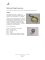
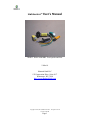
LinkLocator™ User’s Manual
Model 1 shown with MBL Touch probe and fobs
5-Mar-14
iButton®Link LLC
1221 Innovation Drive, Suite #117
Whitewater, WI 53190
http://www.iButton®Link.com
Copyright © 2005,2014, iButtonLink LLC. All rights reserved
3/5/2014 8:29 PM
Page 1
Modification History:
Date
15-JUN-2005
5-MAR-2014
Revisions
Initial Version
Update to include notes on Model 4 and
examples of extended mode commands.
Copyright © 2005,2014, iButtonLink LLC. All rights reserved
3/5/2014 8:29 PM
Page 2
General
The LinkLocator™ is a breakthrough product that allows a 1-Wire® integrator to quickly
and reliably determine which read head was used to attach an iButton® to the 1-Wire™
bus. This location feature is one of the most sought after features in 1-Wire®. While 1Wire® provides a low-cost, reliable, networked solution for electronic keys, guard
tour,and other applications, there has never been a simple way to determine which reader
the iButton® user is using.
Previous attempts to solve this deficiency have included schemes using switches to
switch the iButton® read head on and off the bus so that the location can be implied by
the state of the switch. This approach, while workable for small numbers of probe heads,
introduces switching noise, settling times, and reduced noise immunity for the overall
bus.
The LinkLocator™ uses no switches. Its approach to location is to monitor the bus
traffic and add additional information to the 1-wire data stream during a search or Alarm
Search ROM command. LinkLocator™ can be used with any iButton® probe head.
Simply wire the LinkLocator™ between the probe head and the 1-wire bus. Multiple
LinkLocator™ scan reside on the same bus. The 1-wire behind the LinkLocator™ must
be kept short, a maximum length of 1.5 meters is recommended.
Several models of the LinkLocator™ include additional functionality. The Model 1
LinkLocator™ is designed for use in retrofit applications. The Model 2 is an end user
package with dual RJ45 connectors. The Model 2 is intended for proof of concept
evaluations. The Model 3 (iButton®LinkReader™) is designed for new installations and
is packaged to minimize installation costs.
LinkLocator™ technology is also available for OEM’s as a chip level product for
inclusion in the OEM’s product. The chip level product is available in 8-pin DIP and
SOIC-150 packages. Chip level products are available only under NDA and purchase
minimums apply. Chip level products are available as PB free parts for OEM’s designing
for the EU market.
Copyright © 2005,2014, iButtonLink LLC. All rights reserved
3/5/2014 8:29 PM
Page 3
Software Programming:
Locate Mode:
Locate Mode happens completely within the NORMAL OW protocol mode.
Normal protocol mode is selected by the \O Link Master Command. This is the default
operating mode of LinkLocator™s and is the power up mode.
The LinkLocator™ monitors the 1-wire® ROM search (0xF0) or ROM alarm search
(0xE0). If the selected 1-wire device is down stream of the LinkLocator™, the
LinkLocator™ becomes selected.
The LinkLocator™ then monitors for a 0x00 byte coming down the bus. Receipt of this
byte arms the LinkLocator™. The LinkLocator™ will respond with its serial number
bytes to the next 8 byte reads that are issued by the 1-wire master.
Please note: The 1-wire device selected with the search is NO LONGER SELECTED.
The 0x00 byte caused the 1-wire slave to deselect.
Example using Link45 ASCII commands:
\F is the locator first command. It will search the 1-wire network for the lowest 1-wire
serial number and return it along with the serial number of the locator associated with it.
The Link45 response is of the form
Sxxxxxxxxxxxxxxxx,yyyyyyyyyyyyyyyy
Where:
S indicates the status of the 1-wire search. The possible values of S are:
+ … This is not the last 1-wire device on the network. (There were discrepancies
during the search.
- … This is the last 1-wire slave address on the network. (No discrepancies noted)
E … An error occurred during the search. The search results are invalid.
N ... No slaves were present on the 1-wire network (No presence)
xxxxxxxxxxxxxxxx is the serial number of the 1-wire slave discovered
Copyright © 2005,2014, iButtonLink LLC. All rights reserved
3/5/2014 8:29 PM
Page 4
yyyyyyyyyyyyyyyy is the serial number of the LinkLocator™ associated with
xxxxxxxxxxxxxxxx
If the 1-wire slave was NOT downstream of a LinkLocator™, the Locator serial number
will be FFFFFFFFFFFFFFFF.
Extended Mode:
Extended Mode is used to command and search LinkLocator™s. Please note that 1-wire
slaves from Dallas-Maxim do NOT participate in Extended Mode. A special command
sequence is sent by the Link Master to cause ALL Dallas-Maxim parts to ignore the bus
so that only eXtended mode slaves will participate. LinkLocator™s use FxB
communications during eXtended mode, so there is no conflict with the Dallas-Maxim
parts.
Extended Mode is entered by issuing the \X command.
LinkLocator™ responds to the following ROM commands when in Extended Mode:
Commands common to all eXtended Mode Slaves:
Search ROM (0xF0)
Alarm Search ROM (0xE0)
Skip ROM (0xCC)
Read ROM (0x33)
Match ROM (0x55)
Commands specific to the LinkLocator™
Green LED on (0x12)
Red LED on (0x13)
LED’s off (0x14)
Report Software Version (0x01) Read one additional byte after the 0x01 command. The
major software version will be in the high nibble, the minor software version will be in
the low nibble. The current version of LinkLocator™ returns 0x10 (Version 1.0)
The Family code of LinkLocator™ is 0xFE. The serial number format is exactly the
same as Normal Mode.
Example: The user wishes to produce an inventory of all LinkLocator™s on the bus.
\X ... Specify eXtended mode. The Link45 will respond X<CR><LF>
f ... The Link45 will respond ...
Copyright © 2005,2014, iButtonLink LLC. All rights reserved
3/5/2014 8:29 PM
Page 5
Syyyyyyyyyyyyyyyy<CR><LF>
Where:
S is the status of the search. Possible values are +,-,N,E
yyyyyyyyyyyyyyyy Serial Number of the first LinkLocator™ on the eXtended Bus.
Then the programmer will issue next commands (n) retrieving the serial number of each
of the LinkLocator™s until the Status character is – (indicating that the search is
complete).
Executing Extended Mode Commands
Note: In extended mode the binary mode commands must be sent before a timeout in the
LinkLocator™ expires. It is nearly impossible to hand type the command at the correct
speed. The best methods to send the command are a) through a program or b) by entering
the command into Notepad and then using a copy and paste to enter the entire string at
one time.
Note: An extended mode binary command will only work if it directly follows a reset.
How to check the version number of a LinkLocator™
This example assumes that the LinkLocator™ is the only item on the bus so that the Skip
ROM Command (0xCC) may be used to select the LinkLocator™.
1. Enter extended mode
Command
\X
Response
X<CR><LF>
2. Reset the 1-Wire bus
Command
r
Response
PFE
3. Send the command to read the status. This is a binary mode command.
Copyright © 2005,2014, iButtonLink LLC. All rights reserved
3/5/2014 8:29 PM
Page 6
Command
bCC01FF
Response
bCC0110
The above command consists of the following parts:
b: Enter binary mode
CC: Skip ROM Command – this command selects all slaves on the bus.
01: Command byte 01 is sent to all slaves on the bus
FF: This dummy byte is modified by the slaves when data is transmitted to the host.
In the above command the 0xFF sent to the LinkLocator™ was modified to a 0x10
to indicate the LinkLocator™ version number of 0x10.
How to turn an LED pin on or off on a LinkLocator™
Some models of LinkLocator™ have built in LEDs. Some models may have LEDs
added to them. The following instructions apply to models where an LED exists.
These commands may also be used to toggle IO pins in the Model 4 LinkLocator™. The
IO pins are inside the sealed box. For an OEM product, this could be used as a low level
signal to activate relays that activate a door lock or light an indicator.
This example uses 0000000000000000 as the LinkLocator™ 1-Wire serial number.
Please adjust your command to use the correct LinkLocator™ serial number..
1. Enter extended mode
Command
\X
Response
X<CR><LF>
2. Reset the 1-Wire bus
Command
r
Response
PFE
3. Send the command to read the status. This is a binary mode command.
Turn on Red LED:
Command
b55000000000000000012FF
Response
b55000000000000000012FF
Turn on Green LED:
Command
Response
Copyright © 2005,2014, iButtonLink LLC. All rights reserved
3/5/2014 8:29 PM
Page 7
b55000000000000000013FF
b55000000000000000013FF
Turn off both LEDs:
Command
b55000000000000000014FF
Response
b55000000000000000014FF
The above command consists of the following parts:
b: Enter binary mode
550000000000000000: Match ROM Command – this command selects one slave on
the bus that has an address of 0000000000000000.
12,13, or 14: Command byte that is sent to the specific LinkLocator™
FF: This dummy byte is modified by the slaves when data is transmitted to the host.
In the above command the 0xFF sent to the LinkLocator™ is not changed by the
LinkLocator™.
Copyright © 2005,2014, iButtonLink LLC. All rights reserved
3/5/2014 8:29 PM
Page 8
Model and Wiring Information:
Four models of the LinkLocator™ have existed. Two models currently are available.
Model 1:
The LinkLocator™ Model 1 is supplied as an
encapsulated (potted) package cylinder shaped. The
dimensions are 0.5 inch diameter, 1.5 inch length.
The hookup wires exit the cylinder on one end. This
package is great for OEM applications. The Model 1
may be integrated with the users probe head. It fits in
the MBL Technologies Touch Reader available
separately. The Model 1 is shown inside a MBL
Technologies WeatherTight Enclosure. The Model 1
is appropriate for retrofit applications.
The wire designations are:
Orange (+5V) (optional but recommended)
Blue ... Master bus 1-wire
Yellow ... Located bus 1-wire
Black ... Ground
Black ... Ground
Green ... To BiColor LED on MBL Touch Reader
Brown ... To BiColor LED on MBL Touch Reader
Copyright © 2005,2014, iButtonLink LLC. All rights reserved
3/5/2014 8:29 PM
Page 9
Model 2:
Note: This model is deprecated.
The LinkLocator™ Model 2 is supplied as a packaged unit with enclosure box, MBL
touch reader, and embedded LinkLocator™. The 1-wire network connections are RJ45.
This is an end user package intended for proof of concept testing. Indoor use only.
Copyright © 2005,2014, iButtonLink LLC. All rights reserved
3/5/2014 8:29 PM
Page 10
Model 3 (Also known as the iButton®LinkReader™)
Note: This model is deprecated.
The Model 3 (iButton®LinkReader™) is a tight integration of the LinkLocator™ and the
MBL touch reader. The LinkLocator™ is implemented as a “little round board” attached
to the pins on the back of the MBL Touch Reader. This model is designed for new
installations. It is designed to optimize installation costs.
The Model 3 is supplied with 24 inch pig tail connection wires.
Blue – 1-Wire communications
Black – Ground
Orange – Optional (Recommended) +5V DC
Note: For outdoor use, we recommend using the Model 3 with the MBL Weather Tight
enclosure.
The hole recommended for the iButton®LinkReader is a 20mm “Double D”.
Copyright © 2005,2014, iButtonLink LLC. All rights reserved
3/5/2014 8:29 PM
Page 11
Model 4
The Model 4 provides LinkLocator™ technology in an
easy to use MS style case with an RJ-12 jack for an
external iButton® read head. This package provides ease
of use and flexibility for iButton® read applications.
The RJ-12 jack has the following pin-out:
Pin
1
2
3
4
Signal
No Connection
1-Wire™
Ground
AUX line from Link
The Model 4 does not expose any LED signals.
Internally, the LED signals affect the test points in the following ways:
Powerup state: T1:High, T2:Low,T3:High,T4:High
0x12: Red LED ON: T1:Low, T2:Low,T3:High,T4:High
013: Green LED On: T1:High, T2:Low,T3:High,T4:Low
0x14: Turn off LEDs: T1:High, T2:Low,T3:High,T4:High (this is the same as power up)
All of the test pins T1-T4 are connected to the microprocessor via a 470 Ohm resistor.
The 1-Wire +5 supply should be used for the positive side of an LED, if used with the
internal connections. 1-Wire +5 is available in the round test point between J2 and T4.
Copyright © 2005,2014, iButtonLink LLC. All rights reserved
3/5/2014 8:29 PM
Page 12
Disclaimers:
USE OF iButton®Link PRODUCTS IN MEDICAL AND AIRCRAFT OR OTHER TRANSPORTATION
SYSTEMS. iButton®Link Products are not authorized for use in, or in connection with Surgical implants, or
as critical components in any medical, or aircraft, or other transportation devices or systems where failure to
perform can reasonably be expected to cause significant injury to the user, without the express written
approval of an Executive Office of iButton®Link. Such use is at Buyer's sole risk, and Buyer is responsible
for verification and validation of the suitability of Products incorporated in any such devices or systems.
Buyer agrees that iButton®Link is not liable, in whole or in part, for any claim or damage arising from such
use and shall have no obligation to warranty such Products. Buyer agrees to indemnify, defend and hold
iButton®Link harmless from and against any and all claims, damages losses, costs, expenses and liabilities
arising out of or in connection with Buyer's use of iButton®Link Products in such applications to the extent
Buyer has not obtained the express written approval of an Executive Officer of iButton®Link.
COMPLIANCE WITH U.S. EXPORT REGULATIONS. iButton®Link Products (including samples) are
subject to the export control laws and regulations of the United States and to the laws and regulations of the
country in which the Products are received. Products may not be sold, leased or otherwise transferred to
restricted end-users or countries. Buyer hereby agrees to comply with all applicable export control laws and
regulations and will not use or export iButton®Link Products, directly or indirectly, in violation of these laws.
Copyrights: As used in this document 1-wire and iButton® are the registered trademarks of Maxim
Computer Products. FxB is the trademark of Alicit Software Engineering, LLC LinkLocator™ and
iButton®LinkReader are the trademarks of iButton®Link LLC.
Copyright © 2005,2014, iButtonLink LLC. All rights reserved
3/5/2014 8:29 PM
Page 13