1
TECHNICAL MANUAL
WEIGHT INDICATOR
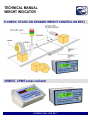
E-CHECK: STATIC OR DYNAMIC WEIGHT CONTROL ON BELT
3590EXT, CPWE series indicator
E-CHECK_03.00_12.05_EN_T
3590EXT, CPWE series indicator
E-CHECK_03.00_12.05_EN_T
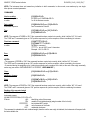
INDEX
1. REQUIREMENTS FOR AN EFFECTIVE INSTALLATION ................................................................................................. 2
1.1 ELECTRICAL PRECAUTIONARY MEASURES .......................................................................................................... 2
1.1.1 CABLE CLASSIFICATION................................................................................................................................. 3
1.1.2 RECOMMENDED DISTANCES AMONG CABLES ........................................................................................... 3
1.1.3 MAXIMUM CABLE LENGTH ............................................................................................................................. 3
1.2 EARTHING SYSTEM ................................................................................................................................................... 4
2. INSTALLING ....................................................................................................................................................................... 5
2.1 WEIGH MODULE ......................................................................................................................................................... 5
2.2 WEIGHING BELT ......................................................................................................................................................... 6
2.3 CADENCE BELT .......................................................................................................................................................... 7
2.4 DOWNSTREAM BELT ................................................................................................................................................. 7
2.5 CYCLE ENABLING AND RESTARTING COMMANDS ................................................................................................ 8
2.6 ALARM, EXPELLER AND TRAFFIC LIGHT / SORTER ............................................................................................... 8
3. SETUP ENVIRONMENT ..................................................................................................................................................... 9
3.1 SET-UP ENVIRONMENT BLOCK DIAGRAM ............................................................................................................ 11
3.2 DESCRIPTION OF THE STEPS ................................................................................................................................ 16
4. CALIBRATION .................................................................................................................................................................. 47
4.1 CALIBRATION PROCEDURE .................................................................................................................................... 47
4.2 LINEARISATION POINTS .......................................................................................................................................... 49
4.3 ZONE OF USE DIFFERENT THAN THE ZONE OF CALIBRATION:......................................................................... 50
4.4 QUICK ZERO CALIBRATION .................................................................................................................................... 50
5. DISPLAY OF THE GRAVITY ACCELERATION AND CORRECTION OF THE WEIGHING ERROR DUE TO THE
DIFFERENT GRAVITATIONAL ACCELERATION BETWEEN CALIBRATION ZONE AND UTILISATION ZONE. ........... 51
6. FUNCTION OF THE OPTOISOLATED INPUTS............................................................................................................... 52
7. FUNCTION OF THE OUTPUTS ........................................................................................................................................ 53
8. SERIAL OUTPUTS ........................................................................................................................................................... 54
8.1 RS 485 CONNECTION .............................................................................................................................................. 55
8.2 PC CONNECTION ..................................................................................................................................................... 57
8.3 PRINTER CONNECTION........................................................................................................................................... 57
8.4 TRANSMISSION PROTOCOLS ................................................................................................................................. 57
8.5 TRANSMISSION MODES .......................................................................................................................................... 59
8.6 SERIAL COMMANDS FORMAT ................................................................................................................................ 59
9. ANALOGUE OUTPUT (OPTIONAL) ................................................................................................................................ 62
9.1 OPERATING MODES ................................................................................................................................................ 62
9.1.1 OUTPUT ON THE GROSS WEIGHT .............................................................................................................. 62
9.1.2 OUTPUT ON THE NET WEIGHT .................................................................................................................... 64
9.1.3 OUTPUT WITH VALUE FROM THE ARTICLE FOR THE BELT SPEED MANAGEMENT ............................. 64
9.2 CONFIGURATION ..................................................................................................................................................... 65
10. PROGRAMMING THE PRINTOUTS ............................................................................................................................... 66
10.1 PROGRAMMING EXAMPLE .................................................................................................................................... 68
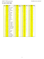
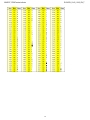
10.2 ASCII CODE TABLE ................................................................................................................................................ 69
10.3 LIST OF PRINT BLOCKS......................................................................................................................................... 71
10.3.1 ORDER BY KIND .......................................................................................................................................... 71
10.3.2 NUMERICAL ORDER .................................................................................................................................... 77
10.4 BLOCKS WITH PARAMETERS ............................................................................................................................... 82
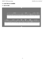
11. ELECTRICAL SCHEMES ............................................................................................................................................... 89
11.1 BACK PANEL ........................................................................................................................................................... 89
11.2 MOTHER BOARD .................................................................................................................................................... 90
11.3 I/O EXPANSION BOARD ........................................................................................................................................ 92
11.4 DISPLAY BOARD .................................................................................................................................................... 93
1
3590EXT, CPWE series indicator
E-CHECK_03.00_12.05_EN_T
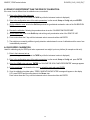
1. REQUIREMENTS FOR AN EFFECTIVE INSTALLATION
To obtain the best results it is recommended to install the indicator and the platform (or transducer) in a place with the
following conditions:
A flat, level surface on which to rest
Stable and vibration free
No dust or strong vapours
No draughts
Make sure the platform is level or that the loading cells are resting evenly
Moderate temperature and humidity (15-30°C and 40-70%)
Do not install anywhere where there is the risk of explosion
All the indicator connections have to be made respecting the rules applicable in the zone and in the installing
environment. Respect the recommended electrical precautionary measures described in section “ELECTRICAL
PRECAUTIONARY MEASURES”.
Make sure that the grounding is made correctly, see section “EARTHING SYSTEM”.
Everything not expressly described in this manual has to be considered as improper use of the equipment.
Avoid welding with load cells installed.
Use waterproof sheaths and couplings in order to protect the load cell cables.
Use a waterproof junction box to connect the cells.
1.1 ELECTRICAL PRECAUTIONARY MEASURES
Mains power supply is restricted to within ± 10% of the rated voltage
Electric protections (fuses etc.) are provided by the technician installing the instrument.
Respect the recommended minimal distances that are mentioned for the various cable categories, see sections
“CABLE CLASSIFICATION” and “RECOMMENDED DISTANCES AMONG CABLES”.
The extension leads of the load cells or signal amplifiers, used for the connection of the serial ports and analogue
output must be within the allowed maximum lengths, see section “MAXIMUM CABLE LENGTH”.
The extension leads of the load cells or signal amplifiers must be screened. In addition they must be laid on their
own in a raceway or metal pipe as far away as possible from the power supply cables.
Install “RC” filters on the contactor coils, on the solenoid valves and on all devices producing electric
disturbances.
If it is possible that condensation could form inside the weight transmitter it is advisable to leave the instrument
powered at all times.
2
3590EXT, CPWE series indicator
E-CHECK_03.00_12.05_EN_T
Every shielded cable or not (for instance PC cable, cell cable, power supply cable) connected to the indicator
should be as shorter as possible, then you have to come out of the shield the minimum length of cable, then
connect to the terminal box;
If the indicator is situated inside an electric panel, the power supply cable should be a shielded cable as shorter as
possible, distant from every coil supply cable, inverter, electromotive force, etc. and in addition dedicate an
uncoupler transformer in order to feed the indicator only.
1.1.1 CABLE CLASSIFICATION
The various cables are classified depending on the transmitted signals:
Category I
- Field bus, LAN
- Shielded data cables (RS232 …)
- Shielded cables for analogue/digital signals < 25V (sensors, load cells…)
- Low tension power supply cables (< 60V)
- Coaxial cables
Category II
- DC supply cables with tension > 60V and < 400V
- AC supply cables with tension > 25V and < 400V
Category III
- Power supply cables with tension > 400V
- Telephone cables
Category IV
- Any cable subject to lightning
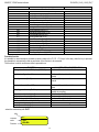
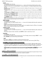
1.1.2 RECOMMENDED DISTANCES AMONG CABLES
- When the cables are laid next to each other, these must be at the distances in the table below
- These distances are valid if in the air; these are reduced if the raceways are separated by grounded metallic shields.
- Different category cables can cross each other (90°)
Category I
Category II
Category III
Category IV
≥ 100 mm
≥ 200 mm
≥ 500 mm
≥ 100 mm
≥ 500 mm
≥ 500 mm
1.1.3 MAXIMUM CABLE LENGTH
LOAD CELL CABLE
The maximum reachable length from the line using the appropriate load cell cable is:
- 50 m with cable 6 x 0,25 mm2
- 100 m with cable 6 x 0,5 mm2
3
3590EXT, CPWE series indicator
E-CHECK_03.00_12.05_EN_T
RS232 CABLE
The maximum reachable length from the line using the RS232 cable with a maximum baud rate of 19200, is about 15 m.
RS485 CABLE
The maximum reachable length from the line with the use of the appropriate cable for RS 485 connections (see section “RS
485 CONNECTION”), and with baud rate up to 9600, is about 1200 meters.
ANALOG OUTPUT CABLE
The maximum length of the analogue output cable in current is:
- 100 m with cable 2 x 0,25 mm2
- 150 m with cable 2 x 0,5 mm2
- 300 m with cable 2 x 1 mm2
The maximum length of the analogue output cable in voltage is:
- 50 m with cable 2 x 0,25 mm2
- 75 m with cable 2 x 0,5 mm2
- 150 m with cable 2 x 1 mm2
1.2 EARTHING SYSTEM
For the right earthing and the optimal functioning of the system, it is necessary to create a point of ground in proximity to the
indicator, on which connect the ground wire (of the indicator) and its shielded cables, see the next paragraph “POINT OF
GROUND OF THE INDICATOR”.
Connect the load cells, the possible junction box, the weighing structure and the ground point of the indicator directly to the
earth bar of the panel (if present), or to a grounding pole, according to the type of application, this will be called the common
point of ground.
POINT OF GROUND OF THE INDICATOR
Create a point of ground in proximity to the indicator, in which one connect the earth of the indicator and the shielded cables
connected (load cell cable, serial ports cables, etc). For example one can use an end connector terminal block, then
connect this point to the ground using a cable having a 4mm² cross-section.
Connect the terminal 24 (EARTH SHIELD) and the case earthing to the common point of ground.
LOAD CELLS AND JUNCTION BOX
-
-
In the case the load cells are connected to the indicator through a junction box, it is necessary to connect the sheathing
of the cells cables and indicator cable to the earthing of the junction box (refer to the junction box manual) and connect
this to the earth.
If the load cells are connected directly to the indicator (without the junction box), it is necessary to connect the
shieldings of the load cell cables directly to the common point of ground, using a cable having a 4mm² cross-section if
the common point of ground is situated a few meters, otherwise through a copper cable having at least a 16 mm² crosssection, or more for longer distances. In both cases it is also necessary:
- Connect to each cell, the top with the bottom of the cell through a copper braid having at least a 16 mm² cross section;
the top should be short-circuited with the plane of the weighing structure, and the bottom must be connected to earth
through a copper braid having at least a 16 mm² cross-section.
- All the grounding cables must have an adequate length, in order to obtain an overall resistance of grounding
system less than 1 Ω.
WEIGHING STRUCTURE
Connect the weighing structure and the possible connected structures (for example silos that release material on the
weighing structure) to the earth through copper cables having at least a 16 mm2 cross-section.
4
3590EXT, CPWE series indicator
E-CHECK_03.00_12.05_EN_T
CONNECTED SERIAL CABLES AND INSTRUMENTS
Ground the cable’s shield both at the common earthing point (at the cable termination on the indicator side) and at the
earthing of the connected instrument (at the cable termination on the connected instrument side) and ground the earth
connection of the connected instrument using the copper cables having at least a 16 mm2 cross-section.
To avoid possible side effects, the earth references of the connection and power supply cable of the indicator and of the
connected instrument must be at the same potential.
GENERAL NOTES:
In the case the weighing system regards great and/or outdoor structures, like weighbridges:
-
the cable cross-section must be greater (for example 50 mm2 instead of 16 mm2 and 100 mm2 instead of 50
mm2), because the voltage into play is greater (for example thunderbolts);
-
the ground pole must be positioned at a distance of at least 10 metres from the weighbridge structure;
-
one needs to open the SENSE inside the indicator in order to offset the drifts due to the increase in
temperature.
One should check and remove, if necessary, the connection between the earth and the neutral wire of the electrical
installation.
2. INSTALLING
IMPORTANT: Respect the electrical precautionary measures shown in section “REQUIREMENTS FOR AN EFFECTIVE
INSTALLATION”.
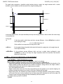
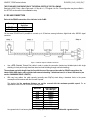
2.1 WEIGH MODULE
After having followed the instructions regarding the platform or weigh module, the screened cable leading from the load
cell(s) must be connected to the instrument through the terminal board, see section “ELECTRICAL SCHEMES”.
The terminal board of the indicator may be connected to the 6-wire weigh module (with use of SENSE), or simply 4-wire; for
this, through jumper J7 and J8 it is possible to choose whether to short-circuit the SENSE with the POWER SUPPLY
(jumpers closed) or not (jumpers open).
The sense allows compensating for any drops in voltage in the part of the cable that connects the instrument to the
transducer. It is useful when the distance between the indicator and the transducer is greater than 10 m.
The 4-pin connectors instead allow just the 4-wire connection.
To make the connection qualified personnel must open the instrument (see terminal board connections section “ELECTRICAL
SCHEMES”).
TAKE NOTE: if there is A SINGLE LOAD WEIGH MODULE, it is possible to make a 6-wire connection (use of the
sense) directly to the terminal board, removing the J7 and J8 jumpers.
If there are two or MORE WEIGH MODULES, one should close the J7 and J8 jumpers (sense and power supply
short-circuited) and make the 4-wire connection.
Normally the indicator comes already connected to the platform and is ready to use. If this is a LEGAL version
instrument, access to the connection will be subject to a legal SEAL.
Follow the instructions for preparing the platform for use.
5
3590EXT, CPWE series indicator
E-CHECK_03.00_12.05_EN_T
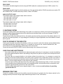
SIG +
SIG SEN +
SEN EXC +
EXC -
SIGNAL +
SIGNAL REFERENCE +
REFERENCE POWER SUPPLY +
POWER SUPPLY -
See section “ELECTRICAL SCHEMES” for further information.
2.2 WEIGHING BELT
The system must be made so that it contains the vibration caused by the movement of the belt.
It is furthermore important to pay attention to the disposition of the cable from the belt (motor), in order to avoid
disturbances during the acquisition of the weigh.
In the weighing in movement, the belt speed must be regulated in order to allow a sufficient time for the data acquisition.
In any case it is advisable to regulate the belt speed at the same speed of the cadence belt or vice versa, in order to avoid
further vibration on the system.
CORNER EQUALIZATION
To obtain the highest performance, in terms of precision, one has to verify the weight difference between the corners.
If necessary, execute the equalization of the corners, depending on the type of application made, in order that the result,
both statically and dynamically, depends as little as possible on the pack position.
In the dynamic weighing mode, it is essential to have the equalized signal between the start and the end of the weighing
belt.
6
3590EXT, CPWE series indicator
E-CHECK_03.00_12.05_EN_T
COMMAND OUTPUT FOR THE WEIGHING BELT
The indicator’s terminal is fitted with the OUT2 output at N.O. contact, managed by the instrument for enabling / disabling
the weighing belt (closed contact to enable the belt)
In case one executes the weigh by manually positioning the pack, and it is required to enable the belt only when the weight
is acquired (to execute the automatic evacuation), it is possible to use the tolerances output, from OUT5 to OUT11 (see
section “FUNCTION OF THE OUTPUTS”), or the expulsion output, OUT4, all managed in the evacuation phase.
START AND STOP WEIGH PHOTOCELLS
If it is required, it is possible to install 2 photocells on the weighing belt, which are to be connected to the indicator in order
to control the weight acquisition weigh; the instrument’s terminal is fitted with:
- IN2 input (start photocell), required in all the functioning modes with photocells, to command the start of weighing
operations;
- IN5 input (stop photocell), required in the functioning mode with 2 photocells, to command the end of weighing operations;
The photocells must be positioned respectively at the start and at the end of the weighing belt.
NOTE: For the connection of the inputs and outputs, follow the electrical schemes at section “ELECTRICAL SCHEMES”.
2.3 CADENCE BELT
For the optimal acquisition of the weighs, it is required to regulate the distance between the packs, in order to guarantee the
affluence with only a pack at a time on the weighing belt.
Furthermore, to avoid the affluence of further packs on the stopped belt, it is required to control the cadence belt by
verifying also the instrument’s outputs.
If the distance between the packs is already externally regulated it is sufficient to manage the cadence belt stop when the
weighing belt has stopped.
COMMAND OUTPUT AND PHOTOCELL FOR THE CADENCE MANAGEMENT
The indicator’s terminal is fitted with the OUT1 output at N.O. contact, managed to enable / disable the cadence belt (closed
contact to enable the belt), in order to regulate the distance between the packs, where these are not already externally
regulated.
To disable the cadence belt the instrument has to manage a photocell that tests the presence of the pack on the cadence
belt, in order to stop the belt only if necessary.
In order to do this, the instrument’s terminal is fitted with the IN3 input, for the connection of the CADENCE photocell.
NOTE: For the connection of inputs and outputs, follow the electrical schemes at section “ELECTRICAL SCHEMES”.
2.4 DOWNSTREAM BELT
For the optimal evacuation of the pack at the end of the weigh acquisition, in particular during the stops, it is required to
stop the downstream belt when the weighing belt has stopped, by verifying the OUT2 output at N.O. contact (closed contact
to enable the belt).
CONSENSUS FROM DOWNSTREAM MANAGEMENT
During a block or a processing phase on the downstream belt, it may be required to stop the weighing belt, to avoid the flow
of further packs.
The management of the weighing belt block must be done through the cycle enabling IN1 input (close input to enable the
cycle).
7
3590EXT, CPWE series indicator
E-CHECK_03.00_12.05_EN_T
It is important to disable the input at the end of the eventual weigh in progress, in order to avoid its cancellation; it is
possible to set a block delay in order to allow the end of the eventual weigh under way, when the input is disabled without
verifying the weighing belt status (see the << rit.bLk >> step).
NOTE: For the connection of inputs and outputs, follow the electrical schemes at section “ELECTRICAL SCHEMES”.
2.5 CYCLE ENABLING AND RESTARTING COMMANDS
To start the automatic weighing cycle, and consequently the enabling of the input/output section, the instrument’s terminal
is fitted with the IN1 input (closed input to enable the cycle).
It is possible to exclude the management of this input, in order that the cycle is always enabled (see << diS.d.st >> step).
Furthermore, during the weighing cycle, depending on the configured functioning mode, it is possible to wait for an external
command before restarting the system (for example after an error condition).
To do this, the instrument’s terminal is fitted with the IN4 input (input closed for an instant to restart).
NOTE: For the connection of inputs and outputs, follow the electrical schemes at section “ELECTRICAL SCHEMES”.
2.6 ALARM, EXPELLER AND TRAFFIC LIGHT / SORTER
The indicator’ terminal is fitted with:
- OUT3 output with N.O. contact, managed to indicate an error status
- OUT4 output with N.O. contact, managed for the automatic expulsion of the out of tolerance pack (closed contact to
indicate the reached level) in order to control a traffic light or divert the product through a sorter.
For the functioning details see user manual, USER.MAN.REF..
NOTE: For the connection of inputs and outputs, follow the electrical schemes at section “ELECTRICAL SCHEMES”.
8
3590EXT, CPWE series indicator
E-CHECK_03.00_12.05_EN_T
Part reserved for the Authorised Technical Personnel
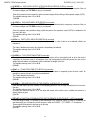
3. SETUP ENVIRONMENT
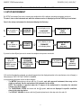
By “SETUP environment" we mean a certain menu inside which all the indicator operating parameters can be set.
To enter it, turn on the instrument and, while the software version is displayed, press the TARE key for an instant.
Once in the set-up environment, the instrument displays the first step.
1)
“ TECH ”
for an instant on
the display
ACCESS
PASSWORD
DISABLED
“ USER - PRESS
KEY ”
for an instant on
the display
ACCESS
PASSWORD
ENABLED
“LAnG”
on the display on top;
COMPLETE SET-UP
MENU
(technical
personnel).
“LANGUAGE”
on the display below
or
2)
“PrG.VEr”
on the display on top
PARTIAL SET-UP
MENU
(only user)
“FIRMWARE”
on the display below
If you are in choice 2) and you want to access the complete set-up menu one should:
Press TARE
during the
visualisation of the
“USER” message
on the display
ENTER THE
PASSWORD
SUBSTITUTING
THE DISPLAYED
(*) VALUE
PRESS
“ENTER”
“TECH ”
for an instant on
the LCD display
COMPLETE
SET-UP
MENU
(technical
personnel).
(*) If one has forgotten the password, one should communicate the displayed number to the manufacturer, who will supply a
valid password JUST FOR THAT SPECIFIC NUMBER.
In the parameter description and in the block diagram
- The METRIC parameters are shown with the (*) symbol, and, with approved instrument, these may not be
visible or read only. See the explanation of the parameter for the details.
NOTE: The indicator is approved when the J1 jumper of the motherboard is closed(see the electrical
scheme in the final chapter).
- The CONDITIONAL STEPS are shown with the (§) symbol, and are not displayed in specific conditions,
shown in the step description.
- The DEFAULT VALUES are shown with the (!) symbol placed next to the step and at the end of it.
9
3590EXT, CPWE series indicator
E-CHECK_03.00_12.05_EN_T
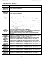
FUNCTION OF THE KEYS IN THE SET-UP ENVIRONMENT
KEY
FUNCTION
F5
Allows to print the steps of the setup environment and the corresponding set values,
and a heading with additional information about the instrument.
F6, F7
Allow to scroll forwards and backwards in the menu steps or in the parameters
inside a step.
Fn / ENTER
C / DEL
NUMERIC
KEYBOARD
Allows to enter a step or to confirm a parameter inside a step.
Allows to exit a step without confirming any changes made and to go to the previous
level.
Allows entering an alphanumeric input.
The display show the current parameter and its description; generally, when one exits a step the instrument places itself on
the following step.
TO EXIT THE SET-UP ENVIRONMENT, PRESS THE C KEY MANY TIMES UNTIL THE INDICATOR SHOWS:
EXITING SETUP:
SAVE ?
CONFIRM WITH ENTER TO SAVE CHANGES MADE OR PRESS ANOTHER KEY TO NOT SAVE.
PRINTOUT OF THE STEPS OF THE SETUP ENVIRONMENT AND SET VALUES
- If one is displaying the step “LANG”, “F.Mode”, “Setup” or “DiAG.”: by pressing F5, the list of all the steps of the setup
environment and the corresponding set values are printed.
- If one is displaying one step inside to those mentioned above: by pressing F5, the step displayed and the possible internal
steps with the corresponding set values are printed.
In both cases these data are preceded by a heading that contains the name and the version of the installed software, the
serial number of the instrument and a parameter that indicates if the default printouts are present (PRN .DFLT = YES) or
not (PRN.DFLT = NO).
10
3590EXT, CPWE series indicator
E-CHECK_03.00_12.05_EN_T
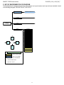
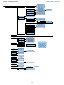
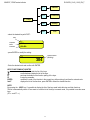
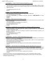
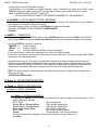
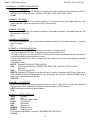
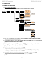
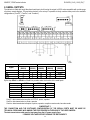
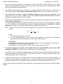
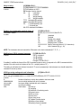
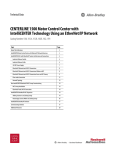
3.1 SET-UP ENVIRONMENT BLOCK DIAGRAM
The following diagram represents the structure of the indicator’s set-up environment; each step has been described in detail
in the following paragraph “DESCRIPTION OF THE STEPS”.
LANG
(!) EN, FR, DE, ES, IT
F.Mode
SETUP
ENVIRONMENT
Setup
Diag.
Prg.Ver.
Weight
Milliv
ADC.Pnt
Display
Keyb.
CTS.ST
F7
B.Level
POWER
C
ENTER
RELE
INPUTS
ANOUT
F6
SER.
SER.NUM
P.TEST
EV.LOG
LEGEND
= USER & TECH MENU’
= ONLY TECH MENU’
(*) = METROLOGICAL PARAMETER
(§) = CONDITIONED STEP
(!) = DEFAULT VALUE
11
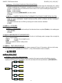
3590EXT, CPWE series indicator
F.Mode
E-CHECK_03.00_12.05_EN_T
F1...F10, 0...9,
POINT, TARE,
Fn, 2ndF, C
(!) Enable, Disable
ENABLE ALL,
DISABLE ALL
SURE?
F.Keys
F1…F10,
2nd F+F1…
2nd F+F10,
Fn+F1…Fn+F10
xxx
dtb
En.dtb
(!) Enable, Disable
En.A.Fld
DESCRIPTION 1
…
ANALOG OUTPUT
EN.KEYS
U.M.
(!) - kg -, - t -, - lb -, - g -
Decim.
(!) X.xxx, X.xx, X.x, X
InIt.
DATABASES,
ARTICLES,
TEXTS
totAL
Reset
(!) Enable, Disable
react
(!) PASS. 0,
InStAb
(!) Enable, Disable
YES, NO
CHECK
LOGO
tXt
In. 0 … In. 14
CFG.tXt
(!) 00 … 31
d.thrES
txt.i
txt.i 0
txt.i 1
txt.i 2
cLr.rAM
SurE?
dtb.PWD
(!) Disable, Enable
00000 … 65534
taMAG
MONTHS
(!) 00 … 99
WEIGH.
(!) 00000 … 99999
Reset
SurE?
12
F1
New
F2
Edit
F3
Delete
F5
Print
3590EXT, CPWE series indicator
CHECk
E-CHECK_03.00_12.05_EN_T
ST.NSTR
STOP, (!) MOVE
EXT.MOV
(!) Disable, Enable
(*) WGh.tyP
STOP, MOVE,
(!) 2.SENS, no.phc
CHECK.t
(!) NORMAL, ART.TR,
TRSHLD
TST.TOL
(!) Enable, Disable
(§) SET.THS
(!) 0011010
(§) SET.RNG
(!) 0011010
(§) TYP.ESP
(!) MANUAL, CORREC.,
COR.MAN, Auto
(§) Rit.Esp.
(!) Disable, Enable
tot.typ
(!) Enable, Disable
WGh.stp
(!) Disable, Enable
0.type
STOP, (!) MOVE
0.START
(!) Disable, Enable
0.BELT
n.W.STOP
TIME
(!) 00 … 60
WEIGHS
(!) 0000 … 9999
(!) 0000 … 9999
n.W.PRNT
(!) 0000 … 9999
(§) smpl.t.e
Disable, (!) Enable
cad.t.e
(!) Disable, Enable
(§) set.dat
n.SMPLS
(!) 01 … 24
PEr.End
(!) 052, 002 … 100
(§) no.phc.p
TIME
per.tot
(!) 100, 002 … 100
St.SP.Sn
(!) 10, 00 … 99
n.SMPLS
(!) 12, 01 … 24
n.MEd
(!) 04, 02 … 12
WGh.SEn
(!) 0.0 … 9.9
thS.rt
XXXXXX
T.M.PES
(!) 00.00 … 99.99
(§) R.ESP.
(!) 01.00, 00.00 … 99.99
(§) I.ESP
(!) 01.00, 00.00 … 99.99
IN.PhC
(!) 00.02, 00.00 … 99.99
POS.PAC
(!) 00.00 … 99.99
EVAC.
(!) 01.00, 00.00 … 99.99
ALARM
(!) 01.00, 00.00 … 99.99
TRF.LGT
(!) 01.00, 00.00 … 99.99
(§) STB.WGT
(!) 1.00, 0.00 … 4.99
2.PAC
(!) 00.00, 00.00 … 99.99
T.W.ViS
(!) 00.50, 00.00 … 99.99
W.UN.OV
(!) 00.00 … 99.99
BLK.D.ST
(!) 00.00 … 99.99
BLK.MOT
(!) 00.00 … 99.99
en.a.pos
dis.d.st
(!) Disable, Enable
N.W.Tol
(!) 00000 … 32767
13
speed
(!) 000 … 255
s.coeff
0.00 … (!) 1.00
belt l.
(!) 0.00 … 9.99
pack. L
(!) 0.00 … 9.99
d.phc
(!) 0.00 … 9.99
3590EXT, CPWE series indicator
Setup
Config
E-CHECK_03.00_12.05_EN_T
Param.
(*) Stabil.
FLT 0 … FLT 3,
H.R.0 … H.R.3
50.fas … 50.slo,
100.fas … 100.slo,
200.fas … 200.slo,
(!) Custom
(*) Auto 0
(!) Enable, Disable
(*) 0.PErC
(!) 2, 00 ... 50
WARMUP
(!) 00 ... 60
(*) 0.Track.
(!) ½, 1, 2, no, ¼
Div.Stb.
(!) 2, 00 … 99
(*) GRAV
9,75001 … 9,84999
(*) Calib.
Decim.
(!) X.xxx, X.xx, X.x, X
U.M.
(!) kg, t, lb, g
nuMbEr oF rAnGE
1
2
rAnGE tyPE
3
Div. 1
(!) 1, 2, 5, 10,
20, 50, 100, 200
Cap. 1
XXXXXX
Div. 2
Cap. 2
Div. 3
Cap. 3
Calib.P
Points
(*) 0.Calib.
Serial
ANOUT
INF.RED
SLOT
(!) SLOT 1, SLOT 2
MODE
(!) AO G, AO N, AO.BELT
AOMA
(!) 00000 … 65535
AOZE
(!) 00000 … 65535
AOMI
(!) 00000 … 65535
(!) None, TARE, 2nd F,
Fn, POINT, C, F1...F10,
0...9, PLT – 0... PLT – 4,
LOC.IN, OFF, - OK -,
ERROR, READY,
START, STOP, RL.OFF,
LNG.KEY, LEVEL,
MNU.FUN
None
RD 6
KEY 1, KEY 2, KEY 3,
KEY 4, KEY 5, KEY 6
RD.BR 6
Tare T.
(§) Lock, Unlock,
Disable
ZOOM.W
(!) Enable, Disable
Pow.Off
(!) Disable, Enable
Bt.Stat.
(!) Disable, Enable
bACkuP
SurE?
Dflt
SurE?
(*) Dflt.t
SurE?
Pwd.Set
(!) Disable, Enable
(*) INI.AL
SurE?
(*) D.SALE
PC.KEYb
(!) 005, 000 … 255
00000 … 65534
(!) NO
YES
(!) 10, 00 ... 50
REM.DSP
(!) NO, YES
KEYuSE
(!)norMAL, rEAdEr
LAYout
(!)Us.En, itAL, FrAn, dEut
14
M.Divis,
M.Range
3590EXT, CPWE series indicator
Serial
E-CHECK_03.00_12.05_EN_T
PORTS
Comprn
Com pc
PC.PR.AX, PC.AX.PR,
PR.PC.AX, PR.AX.PC,
AX.PC.PR, AX.PR.PC
Baud
(!) 9600, 19200, 38400,
57600, 115200, 1200,
2400, 4800
Parity
(!) None, odd, EVEn
Word
(!) 8, 7
Stop B.
(!) 1, 2
CTS.ST.
(!) LOW, NO.CTS,
HIGH, EMUCTS
ERR.CTS
(!) Disable, Enable
pwrprn
(!) pwrint,
extoff, pwrext
Protoc.
Normal, ripe 6, ALIBI,
Cont.
Baud
(!) 9600, 19200, 38400,
57600, 115200, 1200,
2400, 4800
Parity
(!) None, odd, EVEn
Word
(!) 8, 7
Stop B.
(!) 1, 2
CTS.ST.
(!) LOW, NO.CTS,
HIGH, EMUCTS
Add.485
Protoc.
PC.Mode
ComAux
Baud
n
00
(!) StAnd, AFXX,
ripe 6, mondir, ALIBI, SMA,
MODBUS, PROFI.B
(!) Reque., Cont.,
Stabil., - 485 (!) 9600, 19200, 38400,
57600, 115200, 1200,
2400, 4800
Parity
None, Even, odd
Word
8 bit, 7 bit
Stop B.
(!) 1, 2
CTS.ST.
(!) LOW, NO.CTS,
HIGH, EMUCTS
Protoc.
(!) None, Cont., ripe 6
READER
(!) DISABLE,
COM.PRN, COM.AUX
R71.REP.
(!) Disable, Enable
Prn.Fmt
C.F. 01...30
Termin
(!) CR, CR LF,
LF, NO.TERM
DEF.PRN
15
(§) SND.CTS
(!) Disable,
Enable
3590EXT, CPWE series indicator
E-CHECK_03.00_12.05_EN_T
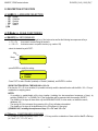
3.2 DESCRIPTION OF THE STEPS
<< LANG >> LANGUAGE SELECTION
- EN
- FR
- DE
- ES
- IT
(!) EN
English
FranÇais
Deutsch
Español
Italiano
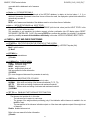
<< F.Mode >> SCALE FUNCTIONING
<< EN.KEYS >> KEYS ENABLING
It is possible to enable/disable each single key of the keyboard as well as the following two sequences of keys:
Fn + Fn
for access to a menu listing all functions
123 + Fn for direct access to a specific function (e.g. number 123)
- select the desired key with F6/F7:
Key
Status
F1
Enable
- press ENTER to modify the setting:
F1
○ Disable
● Enable
- Press F6/F7 to select “Enable” (enabled) or “Disable” (disabled), and ENTER to confirm.
QUICK FUNCTION RECALL THROUGH 999 + 123 + Fn
If the function 123 + Fn is not enabled, it is possible to directly recall the desired function with the 999 + 123 + Fn keys’
combination in weighing phase.
NOTES:
- It’s possible to enable/disable all the keys together (including the above-mentioned sequences of keys), by
selecting “ENABLE ALL” or “DISABLE ALL” (the confirmation will be requested with the message “SURE?”).
- The disabling of the keys will have effect only the WEIGHING PHASE, in other words, not inside the menus,
databases, etc…
- The turning off of the instrument (long pressing of the C key) will always be enabled.
- The disabling of the keys will be applied also on the PC keyboard, if connected.
(!) ENABLE ALL, including the sequences of keys “Fn + Fn” and “123 + Fn”
<< F.Keys >> FUNCTION KEYS COUPLING
It’s possible to modify the function of the F1, F2…..F10 keys, and the combination of these with the 2nd F or Fn keys
(i.e. “2nd F + F1”, “Fn + F2”, etc...).
16
3590EXT, CPWE series indicator
E-CHECK_03.00_12.05_EN_T
F1
Default
F2
Preamble
Fn
Modify
2nd F
List
F. Keys
- select the desired key with F6/F7:
Key
Function
code
Function
F1
304
Art.dtb
- press ENTER to modify the setting:
Code function
(blinking)
F1
304
- Enter the desired code and confirm with ENTER.
KEYS‟ FUNCTIONS IN THIS STEP
scrolls forward inside the list of the keys.
scrolls backward inside the list of the keys.
F1
performs the default of the function pairing of the keys.
F2
inserts the preamble.
ENTER
modifies the code of the function in the current key; while entering it confirms the entered code.
2nd F
displays the list of the functions; press ENTER to select the desired function.
NOTE:
By pressing the . /HELP key, it’s possible to display the list of the keys used inside this step and their functions.
The list is automatically shown. If one wants to scroll the list of the keys in manual mode, it is possible to use the arrow
keys
(F6 and F7 ).
17
3590EXT, CPWE series indicator
E-CHECK_03.00_12.05_EN_T
CODE
100
101
102
103
104
105
106
BASIC FUNCTIONS
Scale zero (ZERO)
Cyclic zero (0.CYCLE)
Tare execution (TARE)
Enable the printer (PRN-ON)
Simple printout (PRINT)
Repetition of last printout (CPY.PRN)
Change visualization weight (WEI.VIS)
107
Change LCD display visualization (LCD.VIS)
2ndF + F9
108
109
110
111
112
113
114
115
116
117
118
119
Lock/unlock keyboard (L.KEYB)
Visualization times ten (Disp.10)
Set time and date (CLOCK)
Diagnostics menu (Diag)
Lock/unlock tare (L.TARE)
Input text configuration (tXt)
Calculator (CALC)
Print and clear partial total (Prn.0.t0)
Print and clear general total (Prn.0.t1)
Print and clear grand total (Prn.0.t2)
Diagnostics peripheral units (P.DIAG)
Com data diagnostics (COM.DAT)
Customized display enabling or change of
visualization if already enabled (CST.DSP)
Input text 0 configuration (txt.0)
Input text 1 configuration (txt.1)
Input text 2 configuration (txt.2)
Input text 3 configuration (txt.3)
Input text 4 configuration (txt.4)
Input text 5 configuration (txt.5)
Input text 6 configuration (txt.6)
Input text 7 configuration (txt.7)
Input text 8 configuration (txt.8)
Input text 9 configuration (txt.9)
Input text cancellation: from 0 to 14, 99 erase
all the texts (txt.rSt)
Print format sending: from 0 to 30 (Send.P.F)
OTHER FUNCTIONS
Format linking to the Simple Printout
(Prn.Fmt)
Format Linking to the Totalisation
(SND.FMT)
Change visualization with enabled zoom
(DAT.VIS) (only for CPWE)
SPECIAL FUNCTIONS
Visualization weight threshold values
(WEI.TR)
Set minimum threshold (tr.LO)
Set maximum threshold (tr.HI)
Print and clear lot total (Rpt)
Article database (Art.dtb)
Print and clear article total (Prn.0.t3)
Article alphabetic search (SEL.ART)
long pressing of F1
long pressing of F2
long pressing of F3
long pressing of F4
long pressing of F5
F4
120
121
122
123
124
125
126
127
128
129
130
131
132
200
201
208
300
301
302
303
304
305
306
18
DEFAULT KEY/S
ZERO
2ndF + ZERO
TARE
Fn + 0
F5
2ndF + F5
2ndF + F8
F8
F9
F10
Fn +F9
F2
F3
2ndF + F3
F1
2ndF + F1
3590EXT, CPWE series indicator
307
E-CHECK_03.00_12.05_EN_T
Visualization weigh report (V.rpt)
PRINTOUT MENU VISUALIZATIONS
Totaliser additional value (Add.VAL)
Set progress digits (Prg.1)
Set progress ticket (Prg.2)
Visualizes partial total (V.t-0)
Print partial total (Prn.t-0)
Reset partial total (0.t-0)
Visualizes general total (V.t-1)
Print general total (Prn.t-1)
Reset general total (0.t-1)
Visualizes grand total (V.t-2)
Print grand total (Prn.t-2)
Reset grand total (0.t-2)
Visualizes article total (V.t-3)
Print article total (Prn.t-3)
Reset article total (0.t-3)
Reset scale totals (0.t-ALL)
Print lot total (Rpt)
Reset lot total (0.W.rpt)
Reading aliby memory (ALIBI)
400
401
402
403
404
405
406
407
408
409
410
411
412
413
414
415
416
417
418
Fn + F3
Preamble function
It is possible to associate also a preamble (numeric value) to the F1, F2…F10 keys. In this way, when the key is pressed,
the preamble is automatically used as parameter of the function to be executed.
The functions to which can be associated a preamble are:
FUNCTION
Change visualization LCD display (LCD.VIS)
VALUE TO SET IN THE PREAMBLE
Number of the desired visualization
Input text configuration (tXt)
Number of the input text that one wants to
modify
Number of the input text that one wants to
cancel
Reset input texts (tXt.rSt)
Send print format (Send.P.F)
Number of the print format that one wants to
send
Number of the format on which one wants to
modify the coupling
Minimum threshold
Maximum threshold
Number of the desired article.
The desired additional value
Number of the desired digit
Number of the desired ticket
Coupling print formats (Prn.Fmt)
Set minimum threshold (tr.LO)
Set maximum threshold (tr.HI)
Article database (Art.dtb)
Totaliser additional value (Add.VAL)
Set progress digits (Prg.1)
Set progress ticket (Prg.2)
- select the desired key with F6/F7.
Key
Function
code
Function
F1
304
Art.dtb
19
3590EXT, CPWE series indicator
E-CHECK_03.00_12.05_EN_T
- press F2 to insert the preamble, select enable and confirm with ENTER:
PREAMBLE
○ Disable
● Enable
- insert the numeric value to combine with the function and confirm with ENTER
Preamble value
(blinking)
PREAMBLE
00000
- insert the desired value through the numeric keyboard and confirm with ENTER (by confirming the value 0, the preamble
is disabled).
If one sets the value 9999 as preamble of a key matched to a database function, by pressing the key the active record is
deselected.
Preamble
Key
Function
code
Function
F1 (1 + F1)
304
Art.dtb
NOTE:
By pressing the 2nd F key it’s possible to see the list keys used in the step.
<< dtb >> CONFIGURATION OF DATABASES
<< En.dtb >> ENABLING DATABASE
It is possible to enable or disable the ARTICLE DATABASE:
Enable
databases enabled.
Disable
databases disabled.
(!) Enable
<< En.A.Fld >> ARTICLE FIELD ENABLING
It’s possible to enable one by one the fields necessary for the application.
Field name
Status
DESCRIPTION 2
○ Disable
● Enable
- Press F6/F7 to select “Enable” (enabled) or “Disable” (disabled), and ENTER to confirm.
- Proceed up to the last suggested field, after which it automatically exits the step.
NOTE: The first article description is always enabled.
<< U.M. >> DATABASE UNIT OF MEASURE
It is possible to set the unit of measure of the ARTICLE database; in relation to the total values: kg, t, lb, g; if the unit
of measure is different than the one of the active scale, the displayed or printed total value will be automatically
20
3590EXT, CPWE series indicator
E-CHECK_03.00_12.05_EN_T
converted with the database’s unit of measure.
(!) kg
<< Decim. >> DATABASE DECIMALS
It is possible to set the number of decimals of the ARTICLE database, in relation to the total values: 1, 2, 3, no
decimal; if the number of decimals is less than the one of the active scale, the displayed or printed total value will be
automatically rounded off.
(!) x.xxx
NOTE: unit of measure and decimals of the database must be set as those those of calibration.
<< InIt. >> INITIALIZE DATABASE and INPUT TEXTS
By pressing ENTER one initialises the ARTICLE DATABASE (with the total values) and the INPUT TEXTS: in this
way all their contents will be cancelled.
The cancellation is not immediate; the indicator requests a further confirmation (the LCD display shows “RESET
DATABASES ? ENTER=YES C=NO”). By pressing ENTER one confirms the operation, by pressing C, the indicator
gives the possibility to cancel all the databases individually in this order: ARTICLE DATABASE, INPUT TEXTS.
<< CHECK >> BELT AND CHECK FUNCTIONING
<< ST.NSTR >> BELT STATUS UPON THE START-UP OF THE SYSTEM
STOP stopped belts; one should enable the belts (OUT1 and OUT2) giving a RESTART impulse (IN4).
MovE belts in motion.
(!) MovE
<< EXT.MOV >>
For use of the manufacturer
(!) Disable
<< (*) WGh.tyP >> TYPE OF WEIGH
STOP weigh upon stopped belt
2.SENS two-sensor weigh
MOVE weigh in motion
no.phc weigh without photo cell
See user manual for further information.
(!) 2.SENS
(*) In case of approved instrument the parameter is read only.
<< CHECK.t >> SELECTING TYPE OF CHECK
Here one selects the type of check which one wants to make:
NORMAL With article and setting of the tolerance thresholds (T1, T2, T3);
ART.TR
With article and setting of minimum and maximum threshold;
TRSHLD Without article and setting of minimum and maximum threshold.
(!) NORMAL
<< TST.TOL >> ENABLING THE TOLERANCE TEST FUNCTION
Enable
enabled tolerance test.
The tolerance test provides for, in this order:
- The tolerance test in respect to a set range.
- The storage of the weigh and data processing (only if the totalisation within tolerance is enabled in the <<
tot.tYP>> step).
- The management of the tolerance indication outputs or of the alarm and expulsion outputs if the weight is out
of tolerance.
Disable disabled tolerance test.
Refer to the user manual for further information.
(!) Enable
21
3590EXT, CPWE series indicator
E-CHECK_03.00_12.05_EN_T
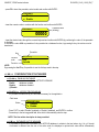
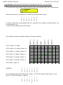
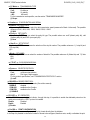
<< (§) SET.THS >> SELECTING THE THRESHOLDS FOR ENABLING THE OUT5 - OUT11OUTPUTS
The instrument offers the possibility of enabling /disabling weight range indication outputs; the LCD display shows:
T3 - THRESHOLD
0001000
1
OUT7
OUT8
OUT5
0
0
0
OUT11
0
OUT10
0
OUT9
0
OUT6
Each numeric value (0 or 1) corresponds to the enabling of a threshold indicator outputs :
To enable a control output, one should switch the 0 into 1, using the F7 key; to disable it, one should switch a 1 into
0, by pressing the F6 key.
To scroll the various outputs press the F8 or F9 keys.
TARGET + t 3
TARGET + t 2
TARGET + t 1
TARGET
TARGET – t 1
TARGET – t 2
TARGET – t 3
Once enabled, the outputs are enabled according to the following conditions:
OFF
ON
OUT10: (Target + t2) < Weigh ≤ (Target + t3)
OFF
OFF
OFF
OFF
OFF
OFF
ON
OFF
OUT9: (Target + t1) < Weigh ≤ (Target + t2)
OFF
OFF
OFF
OFF
OFF
ON
OFF
OFF
OUT5: (Target - t1) ≤ Weigh ≤ (Target + t1)
OFF
OFF
OFF
ON
ON
OFF
OFF
OFF
OUT8: (Target – t2) ≤ Weigh < (Target - t1)
OFF
OFF
ON
OFF
OFF
OFF
OFF
OFF
OUT7: (Target – t3) ≤ Weigh < (Target - t2)
OFF
ON
OFF
OFF
OFF
OFF
OFF
OFF
OUT6: Weigh < (Target - t3)
ON
OFF
OFF
OFF
OFF
OFF
OFF
OFF
EXAMPLES
0
0
1
1
1
0
0
OUT11
OFF
OUT10
OFF
OUT9
OFF
OUT5
OFF
OUT8
OFF
OUT7
OFF
OUT6
OUT11: (Target + t3) < Weigh
1
OUT7
OUT8
OUT5
1
1
1
OUT11
1
OUT10
1
OUT9
1
OUT6
This configuration enables OUT8 if the weight is < (Target - t1), OUT5 if the weight is between (target - t1) and
(target + t1), OUT9 if the weight is > (Target +t1).
22
3590EXT, CPWE series indicator
E-CHECK_03.00_12.05_EN_T
This configuration enables OUT6 if the weight is < (Target - t3), OUT7 if the weight is < (Target - t2), OUT8 if the
weight is < (Target - t1), OUT5 if the weight is between (target - t1) and (target + t1), OUT9 if the weight
is > (Target + t1), OUT10 if the weight is > (Target + t2), OUT11 if the weight is > (Target + t3).
The instrument activates only the enabled outputs; furthermore the instrument enables a single indication output with
each weigh.
The check always starts from the most external thresholds (TARGET - t3; TARGET + t3) and goes toward the target.
As soon as a condition has taken place, the relative output is enabled and the check ends; the remaining thresholds
are not checked.
NOTE: it’s not possible to modify the status of the target outputs (therefore OUT5 is always enabled)
(!) 0011010
(§) Accessible only if the tolerance test is enabled (<< TST.TOL >> step)
<< (§) SET.RNG >> SELECTING THE THRESHOLDS FOR CALCULATING THE TOLERANCE RANGE
The instrument offers the possibility of configuring the tolerance range which, in the weighing phase, discriminates
whether the weigh is within tolerance or not. The LCD display shows:
T 3 - THRESHOLD
0001000
1
TARGET - t2
TARGET - t1
TARGET
0
0
0
TARGET + t3
0
TARGET + t2
0
TARGET + t1
0
TARGET - t3
Each numeric value (0 or 1) corresponds to the enabling of a threshold ; Only the extremities of the tolerance range
should be enabled:
1
1
1
TARGET - t1
TARGET
TARGET + t1
0
0
TARGET + t3
0
TARGET + t2
0
TARGET - t2
EXAMPLES
TARGET - t3
To enable a check threshold, one should switch the 0 into 1 using the F7 key; to disable it, one should switch a 1 into
0, by pressing the F6 key.
To scroll the various thresholds, press the F8 or F9.
1
TARGET - t2
TARGET - t1
TARGET
1
0
0
TARGET + t3
0
TARGET + t2
1
TARGET + t1
0
TARGET - t3
This configuration determines a tolerance range between TARGET - t1 and TARGET +t1
This configuration determines a tolerance range between TARGET - t2 and TARGET +t1
NOTE:
- it’s not possible to modify the status of the target threshold; furthermore, the target is not considered as a tolerance
threshold.
- the tolerance range determines the activation of the OUT4 expeller output.
(!) 0011010
(§) Modifiable only if the tolerance test is enabled (<< TST.TOL >> step).
<< (§) TYP.ESP >> TYPE OF EXPULSION
23
3590EXT, CPWE series indicator
E-CHECK_03.00_12.05_EN_T
Auto
automatic expulsion (management of OUT4)
MANUAL manual expulsion
CORREC. automatic expulsion with possibility of weight correction;
COR.MAN compulsory correction of the out of tolerance weighs.
(!) MANUAL
(§) Accessible only if the tolerance test is selected (<< TST.TOL >> step).
<< (§) Rit.Esp. >> SELECTION OF THE EXPULSION DELAY FROM ARTICLE
It is possible to decide whether to use the expulsion delay time set in the << R.ESP. >> step, for all the articles
selectable from the database, or use the expulsion time entered when compiling the database (section “ENTRY”,
USER MAN.REF.) different for each article selectable from the database.
Enable use of the expulsion delay time configured in the selected article.
Disable use of the expulsion delay time configured in the << R.ESP. >> setp independently from the one
configured in the selected article.
(!) Disable
(§) Accessible only if the tolerance test (<< TST.TOL >> step) is selected and the compulsory correction of the out of
tolerance weighs (<< TYP.ESP >> step) is not selected.
<< (§) tot.tyP >> TOTALISATION OF JUST THE WEIGHS WITHIN TOLERANCE
With the tolerance test enabled, it is possible to choose whether to totalise just the weighs within tolerance or all the
executed weighs. See section “TOTALIZATION OF ONLY THE WEIGHS WITHIN TOLERANCE“ (USER
MAN.REF.). for further information.
Disable totalisation of all the weighs
Enable totalisation of just the weighs within tolerance
NOTE: independently from the configured value, the instrument’s LCD display will show the result of each weigh
either with the weight within tolerance as well as the weight out of tolerance.
(!) Enable
(§) Accessible only if the tolerance test has been selected (<< TST.TOL >> step)
<< (*) WGh.stp >> STOP AFTER WEIGHING
Once the weigh is made, independently of the obtained result, the instrument stops the weighing belt and waits for a
RESTART impulse (IN4) in order to restart.
Enable enabled stop
Disable not enabled stop
(!) Disable
(*) In case of approved instrument the parameter is read only.
<< 0.type >> TYPE OF AUTOMATIC ZERO OF THE WEIGHING BELT
STOP automatic zero from still position
MOVE automatic zero in motion
See section “WEIGHING BELT AUTOZERO” (USER MAN.REF.) for further information.
(!) MOVE
<< 0.START >> ENABLING THE AUTOMATIC ZERO UPON THE RESTART OF THE WEIGHING BELT
Disable
disabled automatic zero
Enable
enabled automatic zero
See section “WEIGHING BELT AUTOZERO” (USER MAN.REF.) for further information.
(!) Disable
<< 0.BELT >> BELT AUTOMATIC ZERO
TIME:
automatic zero at time
Enter the number of minutes after which the automatic zero function will activate automatically.
The settable values go from 0 to 60:
- by setting a value greater than 0 the function is automatically executed each time that the configured number of
minutes is elapsed.
- by setting 0, the function is disabled.
WEIGHS:
automatic zero at weighs
24
3590EXT, CPWE series indicator
E-CHECK_03.00_12.05_EN_T
Enter the number of executed weighs after which the automatic zero function will activate automatically:
The settable values go from 0 to 9999.
- By setting a value greater than 1, the function is automatically executed each time that the configured number of
weighs is reached.
- By setting the value 1, after each weigh the instrument waits for the “PACK EVACUATION” time and at the end
automatically executes the function if the weight is other than 0 and the instrument is in "WAIT FOR PACK".
- By setting 0, the function is disabled.
See section “WEIGHING BELT AUTOZERO” (USER MAN.REF.) for further information
(!) TIME, 00
<< n.W.STOP >> NUMBER OF OUT OF TOLERANCE WEIGHS PER BELT STOP
Set the number of executed out of tolerance weighs after which the indicator stops the weighing belt (OUT2) and
enables the general alarm output (OUT3) for the time set in the << ALARM >> step.
To reenable the weighing belt (and the eventual cadence belt stopped due to the pack presence), one should supply
a restart impulse (IN4).
The settable values are from 0 to 9999; by entering the 0 value the function is disabled.
See section “STOP OF BELTS AFTER A NUMBER OF WEIGHS OUT OF TOLERANCE” (USER MAN.REF.) for
further information.
(!) 0000
<< n.W.PRNT >> SETTING NUMBER OF WEIGHS FOR AUTOMATIC RESETTING OF PARTIAL TOTAL
Set the number of weighs after which the partial total will be printed and automatically reset
The settable values are from 0 to 9999; by entering the 0 value the function is disabled.
(!) 0000
<< (§) smpl.t.e >> WEIGH START ON THE FALLING EDGE OF THE WEIGH START PHOTO CELL
This step allows to enable the weight acquisition following the falling edge of the weigh START photo cell. When the
package engages the weigh start photo cell, the instrument will then wait for the falling edge of the photo cell, which
is given once the package has advanced beyond the photo cell; after this, the package positioning and weigh time is
enabled.
NOTE: in 2 sensor weight time, the weigh stop is in any case supplied by the leading edge of the STOP photo cell.
Disable positioning time start on the leading edge
Enable positioning time start on the falling edge
(!) Enable
(§) Accessible only in the functioning modes with photo cell
<< cad.t.e >> CADENCE TIME START ON THE FALLING EDGE OF THE CADENCE PHOTO CELL
This step allows to enable the cadence time following the falling edge of the CADENCE photo cell. When the
package engages the cadence photo cell, the instrument will then wait for the falling edge of the photo cell, which is
given once the package has advanced beyond the photo cell; after this, the cadence time is enabled.
NOTE: The cadence belt stop (depending on step << 2.PAC >>) is in any case supplied by the leading edge of the
CADENCE photo cell, independently from what is configured in this step.
Disable cadence time start on the leading edge
Enable cadence time start on the falling edge
(!) Disable
<< (§) set.dat >> SETTING THE PARAMETERS FOR WEIGH IN MOTION AND WITH TWO SENSORS
(§) Accessible only if the weigh in motion or with two sensors has been selected (<< WGh.tyP >> step)
<<n.SMPLS>> NUMBER OF SAMPLES FOR CALCULATING A WEIGHT DATUM
Set the number of samples which will be averaged in order to get a weight datum.
25
3590EXT, CPWE series indicator
E-CHECK_03.00_12.05_EN_T
The settable values are from 1 to 24.
Set a low value (like 1, 2, 3 or 4) if the weight is stable or a high weighing speed is requested; one can increase
this value (like from 6 to 12) if the weight shows to be unstable, improving in this way, the weigh accuracy.
If the weight shows to be too unstable, increase the value up to 24, to the disadvantage of the weigh calculation
speed.
The acquisition time of each sample, depends on the filter sampling frequency which is set: if, for example, a
filter with a 25Hz sampling frequency (25 samples per second, ES.FLt.3) has been set, and in this step 12 has
been set, it will take half a second in order to have 12 samples.
(!) 01
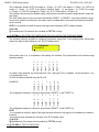
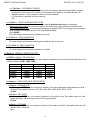
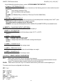
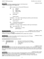
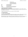
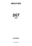
<< PEr.End >> FINAL WEIGHT DATA PERCENTAGE
Enter the percentage of the calculated weight data by the instrument to be used to calculate the weigh.
Once the weigh time has passed (with the dynamic weigh) or after the weigh end photo cell is obscured (with
the two-sensor weigh), the instrument will assess the percentage of the acquired data, specified in this step,
starting from the end of the weigh.
EXAMPLE:
The weight is unstable at the beginning of the weigh and tends to stabilize towards half the weigh.
By setting 50 in this step, the instrument will process 50% of the acquired data during the weigh, starting from
the end:
Weight data acquired in the weigh interval
W
Data used for calculating the
weigh <<PEr.End>>
(50%)
t
The settable values are from 2 to 100.
(!) 052
<< per.tot >> TOTAL DATA PERCENTAGE
The weight data determined by the percentage set in the previous step is ordered and only the best percentage
set in this step is taken into consideration.
The settable values are from 2 to 100.
(!) 100
<< (§) no.phc.p >> WEIGH WITHOUT PHOTO CELL PARAMETERS
(§) Accessible only if the weigh in motion or with two sensors has been selected (<< WGh.tyP >> step)
<<St.Sp.Sn>> SENSITIVITY FOR WEIGH START/STOP
Set the increment/decrement of the minimum weight for the detection of the leading edge and falling edge of the
weight, necessary for determining the beginning and the end of the data acquisition.
The acquisition of the data begins, during the weight leading edge, when the instrument detects three consecutive
weight values which determine an average difference (among those of each value from the previous one) which is
greater than the configured value, and, ends when, during the trailing edge, the instrument detects three consecutive
26
3590EXT, CPWE series indicator
E-CHECK_03.00_12.05_EN_T
weight values which have an average difference (among those of each value from the previous one) greater than the
negative value than th one set.
The value is always expressed in division 1, independently from the scale division; if, for example, the scale division is
5 g and the minimum difference must be 10 g, one should set 10 in this step.
The enabling and the reenabling of the weigh, are in any case, subject to the check of the minimum weigh threshold
(set in the <<thS.rt>> step): the check on the stability for the weigh start/stop, starts after the weight has surpassed
the set minimum threshold.
The settable values are from 0 to 99.
(!) 10
<<n.SMPLS>> NUMBER OF SAMPLES FOR CALCULATING A WEIGHT DATUM
Set the number of samples which will be averaged in order to get a weight datum.
The settable values are from 1 to 24.
Set a low value (like 8, 10 or 12) if the weight is stable or a high weighing speed is requested; one can increase this
value (like 16, 15) if the weight shows to be stable, improving in this way, the weigh accuracy.
The acquisition time of each sample, depends on the filter sampling frequency which is set: if, for example, a filter with
a 25Hz sampling frequency (25 samples per second, ES.FLt.3) has been set, and in this step 12 has been set, it will
take half a second in order to have 12 samples.
In any case the instrument calculates the weight data also when the number of already acquired samples is less than
this value.
(!) 12
<<n.MEd>> NUMBER OF AVERAGES FOR WEIGH CALCULATION
Set the number of consecutive weight values taken into consideration in order to obtain the best weigh:
once the data acquisition is ended, the weigh is obtained by mediating the n consecutive weight values (set in this
step) which have the lowest average difference (among those of each value from the previous one).
The settable values are from 2 to 12.
Set low values (i.e. 4) if the weight is unstable or if a high weighing speed is requested.
It is possible to set higher values (i.e. 8) if the weight is stable, improving the weigh accuracy;
(!) 04
<<WGh.SEn>> SENSITIVITY FOR WEIGH CALCULATION
Set the maximum weight variation required for detecting the weight stability in order to determine the anticipated end
of the data acquisition before the pack evacuation, and therefore, determine the best weigh.
The settable values go from 0,1 to 9,9.
If one sets a value other than zero, the data acquisition ends when the instrument detects n consecutive weight values
(set in step <<n.MEd>>) having an average difference (among those of each value different from the previous one)
which is between the set value and its corresponding negative one.
Greater the weight is unstable, and higher must be this value; Greater the weight is stable and lower must be this
value;
If this value is set at zero, the instrument will give the weight only when the pack evacuates, when the instrument
detects a weight decrease greater than the value set in the <<St.Sp.Sn>> step (advised for applications with a belt in
motion).
The value is always expressed in division 1, independently from the scale division; if, for example, the scale division is
5 g and the minimum difference must be 1 g, one should set 1.0 in this step.
(!) 0.0
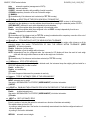
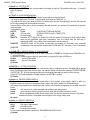
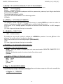
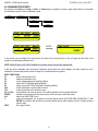
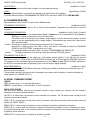
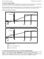
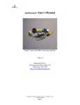
<<thS.rt>> SETTING WEIGH ENABLING, DISABLING AND REENABLING THRESHOLD
Minimum threshold which the weight must surpass in order to enable the weigh start check; the same threshold ends
the weigh (if not yet ended) and reenables the instrument for the following weighs, after the weigh has gone below it.
This threshold must always be less than the target, considering also the sensitivity for the weigh start/stop.
By setting the value 0, the weigh reenables with the passage of zero.
(!) 0.000
27
3590EXT, CPWE series indicator
E-CHECK_03.00_12.05_EN_T
The graph below represents a hypothetic weight tendency during a weigh; the weight increases with a certain
inclination, tends to stabilise and then descends in the weight unloading phase.
W
<<WGh.SEn>>
<<St.Sp.Sn>>
<<thS.rt>>
t
∆t
∆t
In the weigh without sensor, the steps described previously must be programmed, in order to obtain the correct weigh
in the desired time.
In the graph:
∆t
<<thS.rt>>
It’s the time period in which there must be a average difference > than <<St.Sp.Sn>> in order to
start acquiring the weigh
∆t = (1/ set filter frequency) x 3.
If this condition is not respected, the weigh will not start.
It’s the weigh minimum threshold; this threshold is linked to the weigh start, to the weigh stop and
to the weigh reenabling.
<<WGh.SEn>> It’s the maximum average difference which can have n weight values (configured in step
<<n.MEd>>) in order to end early the weight acquisition before the evacuation and therefore
determine the best weigh.
<< TIME >> SETTING THE TIME PERIODS OF THE INSTRUMENT
<< (§) T.M.PES >> TIME FOR WEIGHS (in seconds)
(§) Accessible if the weigh with 2 sensors (<< WGh.tyP >> step) is not selected
Takes on different meanings depending on the selected weigh type (step << WGh.tyP >>):
- Weigh with stopped belt: once the pack positioning time has passed, it defines a maximum time duration of the
weight instability condition after which the error condition is enabled; if, during this time, the weight is stable, it
is zeroed and restarts each time that the weight becomes unstable.
The 0 value disables the function.
- Weigh in motion with 1 photo cell: Once the pack positioning time has passed, only in dynamic weighing, the
instrument samples the weight for the duration of this time, obtaining the final weigh.
- Weigh without photo cell: it defines the maximum duration of the weigh calculation, starting from its enabling;
at the end of this time, if other conditions have not taken place which determine the end of the weigh, the
instrument ends the weigh totalising the value calculated up until that moment.
The settable values go from 0,00 to 99,99.
(!) 01.00
28
3590EXT, CPWE series indicator
E-CHECK_03.00_12.05_EN_T
<< (§) R.ESP. >> EXPULSION OUTPUT ACTIVATION DELAY PERIOD (OUT4) (in seconds)
(§) Accessible only if the tolerance test (<< TST.TOL >> step) is selected and the compulsory correction of the out
of tolerance weighs (<< TYP.ESP >> step) is not selected.
Time which passes from the instant the pack evacuation begins till the closing of the expulsion output (OUT4).
The settable values go from 0,00 to 99,99.
(!) 01.00
<< (§) I.ESP >> EXPULSION IMPULSE DURATION (in seconds)
(§) Accessible only if the tolerance test (<< TST.TOL >> step) is selected and the compulsory correction of the out
of tolerance weighs (<< TYP.ESP >> step) is not selected.
Once the expulsion relay activation delay period has passed, the expulsion output (OUT4) is enabled for the
time set in this step.
The settable values go from 0,00 to 99,99.
(!) 01.00
<< IN.PhC >> PHOTO CELL IMPULSE DURATION (in seconds)
Minimum duration of the impulse coming from the photo cells in order for this to be considered valid by the
instrument.
The value 0 disables the function (the impulse is immediately considered).
The settable values go from 0,00 to 99,99.
(!) 00.02
<< PoS.PAC >> PACK POSITIONING TIME (in seconds)
Time which passes from when the pack obscures the photo cell on the weighing belt to when the pack is
completely on the scale, ready to be weighed. Once the pack positioning time has passed, as soon as the
weight becomes stable, the instrument starts to calculate the weight of the box.
The settable values go from 0,00 to 99,99.
(!) 00.00
<< EVAC. >> EVACUATION TIME OF THE PACK (in seconds)
This parameter allows to establish the time which the pack takes to completely leave the belt, useful, for
example to execute the auto zero with an unloaded belt.
The 0 value disables the function.
The settable values go from 0,00 to 99,99.
(!) 01.00
<< ALARM >> IMPULSE DURATION OF THE GENERAL ALARM (OUT3) (in seconds)
Each time that there is an error condition in the weighing phase, the OUT3 output is enabled for the time set in
this step.
The settable values go from 0,00 to 99,99.
By setting the alarm time equal to 0.00, the alarm will remain active until the error condition has ended or a
restart impulse is given.
(!) 01.00
<< TRF.LGT >> DURATION OF ENABLING FOR THE TOLERANCE OUTPUTS (OUT5 – OUT1) (in seconds)
Once the weigh is made, it is possible to take advantage of the threshold outputs in order to crosscheck the
executed weigh (out of tolerance or within tolerance, under the TARGET – T2, TARGET + T1 thresholds…).
These outputs will enabled for the time set in this step.
The settable values go from 0,00 to 99,99.
(!) 01.00
29
3590EXT, CPWE series indicator
E-CHECK_03.00_12.05_EN_T
<< (§) STB.WGT >> STABILITY TIME FOR WEIGH ACQUISITION (in seconds)
(§) Accessible only if the stopped belt weigh is selected (<< WGh.tyP >> step)
Once the package is positioned, this is the necessary time required for the weight stability condition in order to
acquire the weigh; if during this time, the weight is unstable, it will be zeroed and will restart each time that the
weight returns stable.
The settable values go from 0,00 to 4,99.
(!) 01.00
<< 2.PAC >> DELAY TIME BETWEEN TWO PACKS (in seconds)
Time which adjusts the cadence of the packs which arrive onto the weighing belt.
The settable values go from 0,00 to 99,99.
See section “MANAGEMENT OF CADENCE PHOTOCELL AND BELT” (USER MAN.REF.) for further
information.
(!) 00.00
<< T.W.ViS >> WEIGH VISUALISATION TIME (in seconds)
Upon each weigh acquisition, the instrument’s display shows the acquired weight and the progressive number
of the executed weighs.
In this step one adjusts the time period of these visualisations.
The settable values go from 0,00 to 99,99.
The value 0 disables the function.
(!) 00.50
<< W.UN.OV >> MAXIMUM TIME OF weight UNDERLOAD / OVERLOAD CONDITION (in seconds)
Minimum time duration of the weight UNDERLOAD / OVERLOAD condition in order for it to be considered
valid by the instrument in order to enable the alarm condition for weight in UNDERLOAD / OVERLOAD, end
the weigh cycle and stop the belts.
In order to reenable the cycle it will be necessary to restore the weight and supply an impulse on the
RESTART input (IN.E.2).
The settable values go from 0,00 to 99,99.
The 0 value disables the function.
(!) 00.00
<< (§) BLK.D.ST >> LOCK DELAY FROM DOWNSTREAM (IN6) (in seconds)
(§) Accessible only if the consensus from downstream is not excluded (step << diS.d.st >>) and if the external
handling is not selected (step << EXT.MOV >>)
Minimum duration for disabling the consensus from downstream (IN6) in order for it to be considered valid in
order to end the weighing cycle and stop the belts.
The settable values go from 0,00 to 99,99.
The 0 value disables the function (the weighing cycle ends and the belts are instantaneously stopped).
(!) 00.00
<< BLK.MOT >> IMPULSE DURATION OF EMERGENCY / MOTOR LOCK INPUT (IN.E.4) (in seconds)
Minimum duration of the impulse coming from the EMERGENCY / MOTOR LOCK input (IN.E.4) in order for it
to be considered valid by the instrument in order for it to enable the "EMERGENCY / MOTOR LOCK” alarm
condition, end the weighing cycle, and stop the belts. The cycle will restart as soon as the input is disabled.
The settable values go from 0,00 to 99,99.
The 0 value disables the function (the impulse is instantaneously considered).
(!) 00.00
The following step allows to enter all the weighing belt parameters in order to automatically calculate the weight
positioning time and, only for the dynamic weighing, the average weight time, and the setting of the speed variation
coefficient through the IN7 input.
30
3590EXT, CPWE series indicator
E-CHECK_03.00_12.05_EN_T
<< en.a.pos >> ENABLING THE AUTOMATIC PACK POSITIONING
<< speed >> SETTING OF THE BELT SPEED
Enter the belt speed, in m/min.
By using the variation of time periods function through IN7 input, one needs to set this step and calculate the
time for the maximum speed.
The enterable values are from 0m/min to 100m/min
(!) 000
<< s.coeff >> SETTING THE COEFFICIENT OF SPEED VARIATION
Enter the coefficient of speed variation, related to the minimum speed in reference to the maximum one.
By enabling the IN7 input during the weighing cycle, the << R.ESP. >>, << EVAC. >> and << TRF.LGT >>
times will be moltiplied for the set coefficient.
(!) 1.00
<< belt l. >> SETTING THE BELT LENGTH
Enter the length of the weighing space, in other words, the space in which the weigh takes place. Enter the
value in m, with two decimal digits.
The enterable values go from 0.00m to 9.99m.
(!) 0.00
<< pack. l. >> SETTING THE PACK LENGTH
Enter the length of the longest pack which will be weighed, in m, with two decimal digits.
The enterable values go from 0.00m to 9.99m.
(!) 0.00
<< d.phc >> SETTING THE DISTANCE between THE PHOTO CELLS
Enter the distance of the photo cell from the start of the weighing belt.
The enterable values go from 0.00m to 9.99m.
(!) 0.00
NOTE: The automatic calculation of the pack positioning and weighing time takes place each time that one exits the
<< en.a.pos >> step and at least one of its parameters has been modified (excluding the << s.coeff >> step);
therefore, if one exits the step after having confirmed the already entered values, the calculation is not carried
out.
In any case it is possible to manually correct the weighing and positioning time.
Diagram of the instrument weigh time (with weigh start on the leading edge of the FTC):
ON
FTC status
pack presence
OFF
OFF
A
B
C
A: photo cell obscuring time
B: pack positioning time
C: weigh time
D: control light / expulsion activation time
E: scale ready to execute a new weigh
31
D
E
t (sec.)
3590EXT, CPWE series indicator
E-CHECK_03.00_12.05_EN_T
<< dis.d.st >> EXCLUDING CONSENSUS FROM DOWNSTREAM
Through this step it’s possible to exclude the management of the consensus input from downstream (IN.1), always
enabling the weighing cycle. Excluding the consensus from downstream is useful in cases in which the input is not
necessary, for example if there is no belt and one does not want to use an input for enabling the weighing cycle.
Enable exclusion enabled.
Disable exclusion disabled.
Refer to the user manual (USER MAN.REF.) for further details.
(!) Disable
<< N.W.Tol >> NUMBER OF WEIGHS WITHIN TOLERANCE FOR AUTOMATIC TARGET RECALCULATION
Set the number of weighs within tolerance after which the target is automatically recalculated (for the functioning
details see section “AUTOMATIC TARGET RECALCULATION AFTER N WEIGHS WITHIN TOLERANCE”,
USER MAN.REF.)
The settable values are from 0 to 65535; by inserting the 0 value the function is disabled.
(!) 00000
<< totAL >> TOTALIZER
<< Reset >> CONFIRM RESET
It is possible to select the automatic resetting of the totals when these are printed (Disable) or the resetting upon
request (Enable).
(!) Enable
<< react >> REENABLING OF THE PRINTOUTS
It is possible to set the re-enabling of the simple print function in the following modes: “passage of the net weight by
zero” or “weight instability”.
PASS.0
passage of the net weight by zero
InStAb
instability
NOTE: The totalisation function is always active.
(!) PASS.0
<< LOGO >> TEXT UPON START-UP
At the start-up of the indicator, the LCD display shows a message of 2 lines of 16 characters, which is set in this step,
or a 160x32 pixel photo uploadable from Dinitools™ (“ *.bmp ”monochromatic format is accepted).
(!)
<< tXt >> INPUT TEXTS
<< CFG.tXt >> INPUT TEXT CONFIGURATION
Through this step one can enter, modify or cancel the heading of the input texts which will be filled in during the
weighing through the F4 key of the indicator; refer to the user manual for further specifications. (USER MAN.REF.).
F1
New
F2
Edit
F3
Delete
F5
Print
CFG.tXt
./HELP
Help
32
3590EXT, CPWE series indicator
E-CHECK_03.00_12.05_EN_T
ENTRY
- Press ENTER to enter in the step.
- Select the eventual desired position through the arrow keys (or with the keyboard digit the position number).
- Press F1 to enter the text in the desired position, or the first free position, if an already occupied position has been
selected.
- The display shows “DESCRIPTION” and one can now enter the heading of the input text (up to 16 characters); press
ENTER to confirm.
- The display shows “TEXT” and one can enter the contents of the input text (up to 32 characters); press ENTER to
confirm.
- The display shows “THRESHOLD” and one can enter the maximum number of alphanumeric characters enterable in
the field “TEXT”; press ENTER to confirm.
- The display shows “MANDATORY INPUT”, if one chooses “Enable” it is possible to exit from the input phase only if
the text isn’t null; press ENTER to confirm.
- The display shows “ONLY VOID INPUT”; if one chooses “Enable” it is possible to modify the text only if it is null;
press ENTER to confirm.
- NOTE: The threshold entered here defines also the field length for the compilation through the F4 key in the weighing
phase; if no text is inserted, the length is set at 32 characters.
MODIFICATION
- Press ENTER to enter in the step.
- Select the storage to be modified through the arrow keys (or with the keyboard digit the position number) and
press F2.
- Modify the desired fields, listed in the previous section.
- NOTE: The text entered here defines also the field length for the compilation through the F4 key in the weighing
phase; if no text is inserted, the length is set at 32 characters.
CANCELLATION
- Press ENTER to enter in the step.
- Select the storage to be cancelled through the arrow keys (or with the keyboard digit the position number) and
press F3.
- The indicator requests a further confirmation: press ENTER to confirm or another key to cancel.
PRINTING
- Press ENTER to enter in the step.
Once inside it, press the F5 key to print all the input texts. The LCD display shows the message “PRINT ?”: confirm
with the ENTER key to print the whole input texts’ database.
HELP
By pressing the ./HELP key, it’s possible to see the keys list used in the menu.
The key list is automatically. If you want to see the keys list, in manual mode, use the arrow key (F6 or F7 key).
<< D.THRES >> DATA LENGTH THRESHOLD FROM READER
If one enables the compilation function of the free texts through the bar code reader / badge (see relative manual),
In this step one can define a length (from 00 to 31) which conditions the storage of data ready. If the datum has a
length less or equal to the predefined one; it is stored in the first input text; otherwise it is stored in the second one.
NOTE: the function has been enabled on the serial port selected in the Setup >> Serial >> READER step, or on the
PC KEYBOARD input, by selecting the “Reader” parameter in the Setup >> PC.KEYB >> KEYUSE step.
(!) 00
<< txt.i >> ENTRY OF HEADINGS
Up to 3 lines x 24 characters of text can be entered that will be printed if programmed in the printout formats. The text
entered will remain stored and printed until it is either cancelled or substituted.
<< cLr.rAM >> BUFFERED RAM RESET
The indicator has a buffered RAM memory (not volatile when power is removed) inside which is the database data,
33
3590EXT, CPWE series indicator
E-CHECK_03.00_12.05_EN_T
the input texts, the print formats and the heading.
The cancellation is not immediate; the indicator requests a further confirmation (the display shows “SurE?): press
ENTER to confirm (the indicator exits the SET-UP executing the start-up cycle); press another key to cancel.
Note: - CALIBRATION DATA ARE NOT CANCELLED.
-- THE FUNCTION DOES NOT ENABLE THE STANDARD PARAMETERS OF THE INSTRUMENT
<< dtb.PWD >> SET DATABASE ACCESS PASSWORD
By confirming the Enable setting one may insert a password of up to 5 digits, which will inhibit the entry, modification
or cancellation of the databases, during the weighing.
The settable values run from 0 to 65534; by setting Disable, this password is disabled.
See section “DATABASE ACCESS PASSWORD” (USER MAN.REF.).
(!) Disable
<< taMAG >> TAMAGOTCHI
One enters the “NUMBER of MONTHS” passed (2 digits, MONTHS parameters), and the “NUMBER of the WEIGHS”
made (5 digits, WEIGH. parameter) since the last calibration; after this, one is advised to recalibrate the instrument.
By pressing ENTER one passes to a submenu:
- MONTHS >>>
Setting of Months
- WEIGH. >>>
Setting of Weighs
- Reset
>>>
Clearing of Months and Weighs from the last calibration
If you set the number of months and the weighing to zero, this function will be disabled.
In any case it is possible to activate a choice of the number of months (MAX 99) or the number of weighs (MAX 99999)
by setting at 0 the undesired parameter.
At start-up and every day at 11:00 o’clock, the indicator will be checking for the number of weighing and the number of
months that have passed since the last calibration. If one of the values or both are equal or higher than the previously set
values, the message “WE ADVISE TO RECALIB. SCALE” appears in the display and an intermitting sound is emitted. By
pressing any key, the indicator will make a countdown and then it enters in the normal scale functioning mode.
NOTE: The number of weighs is decreased when, after passing by zero, there is a stable weight and greater than 4
divisions on the scale.
(!) MONTHS 00; WEIGH. 00000.
<< Setup >> SCALE CONFIGURATION
<< Config >> METRIC CONFIGURATION
<< Param. >> METRIC PARAMETERS
<< (*) Stabil. >> FILTERING INTEGRATION
By pressing the ENTER key one accesses the selection of the type and degree of filter intervention for the
stability of the weight indication:
FLT 3 - FLT 0
Simple weighing filter
200.slo, 200.nor, 200.med, 200.fas
200Hz dynamic weighing filter
100.slo, 100.nor, 100.med, 100.fas
100Hz dynamic weighing filter
50.slo, 50.nor, 50.med, 50.fas
50H dynamic weighing filter
H.R.3 – H.R.0
Filter for high resolution systems
Custom
Costumized filter for use of the manufacturer
The higher the filter value, and greater is its intervention relative to the type of filter used.
(!) Custom
34
3590EXT, CPWE series indicator
E-CHECK_03.00_12.05_EN_T
<< (*) Auto 0 >> AUTOZERO AT START-UP
Automatic acquisition of the gross zero at start-up.
Auto 0
● Disable
○ Enable
- Disabled
Auto 0
C.PErC
○ Disable
● Enable
10
ENTER
- Enabled
Clearing percentage
(blinking)
Set the clearing percentage in relation to the capacity (in
between +/-1 and +/- 50 %).
See section “POWER SUPPLY & START-UP” (USER MAN.REF.) for details on the functioning.
(*) with approved instrument,
by confirming the setting of EnAbLE it is possible to modify the clearing percentage between +/-1 and +/-10 %.
(!) Enable, +/-10 %
<< (*) 0.PErC >> ZERO FUNCTIONS IN WEIGHING PHASE
Acquisition of the gross zero through the ZERO key or through the WEIGHING BELT AUTOZERO function.
0.PErC
02
Clearing percentage
(blinking)
Set the clearing percentage in relation to the capacity (in between +/-1 and +/- 50 %).
By entering the 0 value, it’s possible to disable the ZERO functions in the weighing phase.
See section “SCALE ZERO FUNCTION” (USER MAN.REF.) for functioning details.
(*) In case of approved instrument, the settable values are between 0 and 2.
(!) +/-2 %
<< WARMUP >> WARM-UP PHASE
It is possible to set a time in which, during the start-up phase, a brief preheating is made of the instrument
electronics, in order to optimize the weighing.
The settable values go from 00 to 60 sec.
The 00 value disables the function.
(!) 00
<< (*) 0.Track. >> ZERO TRACKING
This menu allows setting the zero tracking, in other words, the compensation parameter of the scale’s thermal
drift. The set value corresponds to the number of stable divisions per 1 second that one desires to
compensate.
TR. ½
+/- half division.
TR.¼
+/- one fourth of a division
TR. 1
+/- one division.
TR. 2
+/- two divisions.
TR. no
tracking disabled.
(*) In case of approved instrument, by entering the step one views the set value; by pressing ENTER it’s
possible to modify the parameter and choose one of the following values: TR. no, TR.. ½, TR. ¼..
(!) TR. ½
35
3590EXT, CPWE series indicator
E-CHECK_03.00_12.05_EN_T
<< (*) Div.Stb. >> DIVISIONS BY STABILITY
In this step one enters the number of divisions by which the instrument detects the weight stability; the higher
the number of divisions, less is the sensitivity, and consequently the stability is more easily detected. The
possible values are 0…99; by setting the 0 value, the check is disabled.
(*) If the indicator is approved, the step is read only.
(!) 2
<< (*) GRAV >> GRAVITY ZONE AND ZONE OF USE
In this step one selects the gravitational acceleration value of calibration and of use of the instrument:
Manual entry of the g value: the instrument is ready for the manual entry of the gravitational acceleration value.
If one enters a wrong g value: the minimum decimal value is proposed (9,75001); by a wrong g value one intends a
decimal number not including between 9,75001 and 9,84999 (included).
(!) g = 9,80655
(*) In case of approved instrument the parameter is read only.
<< (*) CALib. >> SCALE CALIBRATION
See section “CALIBRATION”.
(*) In case of approved instrument some parameters inside this step are read only.
<< (*) 0.CALib. >> ZERO CALIBRATION
See section “CALIBRATION”.
(*) In case of approved instrument the parameter is not visible.
<< Serial >> SERIALS, PRINTOUTS, ETC…
<< PORTS >> SERIAL CONFIGURATION
By pressing ENTER it’s possible to choose the most adequate combination for the use of the three serial ports on the
indicator hardware (COM1, COM2, COM3):
Parameter
PC.PR.AX (!)
PC.AX.PR
PR.PC.AX
PR.AX.PC
AX.PC.PR
AX.PR.PC
COM 1
ComPC
ComPC
ComPrn
ComPrn
ComAux
ComAux
COM 2
ComPrn
ComAux
ComPC
ComAux
ComPC
ComPrn
COM 3
ComAux
ComPrn
ComAux
ComPC
ComPrn
ComPC
<< Comprn >> CONFIGURATION OF PRINTER SERIAL
<< Baud >> SET BAUD RATE
By pressing the ENTER key one accesses the selection of the data transmission speed (measured in Baud =
bit/second). The possible values are: 1200, 2400, 4800, 9600, 19200, 38400, 57600, 115200
(!) 9600
<< Parity >> SET PARITY
By pressing the ENTER key one accesses the selection of the parity bit type. The possible values are: nonE
(absent parity bits), odd (uneven parity bits) e EVEn (even parity bits).
(!) None
<< Word >> SET WORD
By pressing the ENTER key one accesses the selection of the number of data bits. The possible values are: 8 (8
data bits) and 7 (7 data bits).
(!) 8
36
3590EXT, CPWE series indicator
E-CHECK_03.00_12.05_EN_T
<< Stop B. >> SET STOP BIT
By pressing the ENTER key one can then select the number of stop bits. The possible values are: 1 (1-stop bit)
and 2 (2 stop bits)
(!) 1
<< CTS.ST. >> SYNCHRONISM SIGNAL
On the serial line set as COM.PRN the indicator can manage a synchronism signal.
- by using the dedicated CTS (Clear To Send) signal, if one uses the COM2 port, or
- by using the RX input, if one uses the COM1 or COM3 port (in this case, by enabling the function, this input will
be no longer managed for other reception functions).
A device (like a printer) that is slow in processing the data received, can interrupt the transmission temporarily
using this signal.
It is possible to select:
NO.CTS
Disable
(ITALORA WITTY280 and SMT280)
LOW
CTS active low
(LP522/542, EPSON LX300, TM295, TPR)
HIGH
CTS active high
(DP190)
EMUCTS
Emulation of CTS signal: one is asked to enter the number of characters (nChrS) using 3 digits,
which will be transmitted upon each transmission; then one should enter the wait time in
milliseconds (tiME), using 4 digits, from a transmission and the next one.
XON/XOFF XON/XOFF control for the printer. It`s necessary the insertion of the printer reset command
(4 characters in decimal) and the decimal value of XON and XOFF character (17 and 19 of default).
(!) NO.CTS
<< (§) SND.CTS >> SECOND SIGNAL OF SYNCHRONISM
(§) Accessible after having selected “LoW” or “hiGh” in the step << CTS.ST >> if the printer port COM.PRN is set
on the COM2 port.
It’s possible to manage a second signal of synchronism, by using the RX input of COM2 port.
Disable
second CTS disabled
Enable
second CTS enabled
(!) Disable
<< ERR.CTS >> CTS STATUS ERROR
By enabling this error, it is possible to block in advance the print or totalisation function, if recalled with an already
active synchronism signal (see previous step): the indicator display will shows the message “PRINTER ERROR:
CHECK THE CTS!” for a few seconds and return to the weighing phase without carrying out the function.
Press F6/F7 to Enable (enabled) or Disable (disabled), and ENTER to confirm.
(!) Disable
<< pwrprn >> PRINTER POWER SUPPLY
On the indicator board there is a terminal board called V-AUX (auxiliary power supply), thanks to which it is
possible to power the devices (for example a printer); refer to the electric scheme for the characteristics.
In this step one programmes the functioning of the auxiliary output and the management of a possible connected
printer:
pwrext
with instrument on, printer managed and auxiliary output always active.
pwrint
printer managed, auxiliary output active only when the instrument executes a printout.
extoff
printer managed and auxiliary output always active; the start-up characters are sent to the printer,
because the printer is considered to be configured in the energy saving mode.
(!) pwrext
<< Protoc. >> SELECTS PROTOCOL
Normal
Print
ripe 6
Dini Argeo 6-digit repeater.
ALIBI
print/alibi memory
Cont.
continuous transmission
For the protocol specifications, see section “TRANSMISSION PROTOCOLS”.
(!) Normal
37
3590EXT, CPWE series indicator
E-CHECK_03.00_12.05_EN_T
<< Com pc >> PC SERIAL CONFIGURATION
<< Baud >> SET BAUD RATE
By pressing the ENTER key one accesses the selection of the data transmission speed (measured in Baud =
bit/second). The possible values are: 1200, 2400, 4800, 9600, 19200, 38400, 57600, 115200.
(!) 9600
<< Parity >> SET PARITY
By pressing the ENTER key one accesses the selection of the parity bit type. The possible values are: nonE
(absent parity bits), odd (uneven parity bits) e EVEn (even parity bits).
(!) None
<< Word >> SET WORD
By pressing the ENTER key one accesses the selection of the number of data bits. The possible values are: 8 (8
data bits) and 7 (7 data bits).
(!) 8
<< Stop B. >> SET STOP BIT
By pressing the ENTER key one can then select the number of stop bits. The possible values are: 1 (1-stop bit)
and 2 (2 stop bits)
(!) 1
<< CTS.ST. >> SYNCHRONISM SIGNAL
On the serial line set as COM.PRN the indicator can manage a synchronism signal
- by using the dedicated CTS (Clear To Send) input, if one uses the COM2 port, or
- by using the RX input, if one uses the COM1 or COM3 port (in this case, by enabling the function, this input will
no longer be managed for other reception functions).
A device (like a printer) that is slow in processing the data received, can interrupt the transmission temporarily
using this signal.
It is possible to select:
NO.CTS Disabled (ITALORA WITTY280 e SMT280)
LOW
CTS active low (LP522/542, EPSON LX300, TM295, TPR, LP542PLUS, TTP243, LP542S,
SMTPLUS)
HIGH
CTS active high (DP190)
EMUCTS Emulation of CTS signal: one is asked to enter the number of characters (nChrS) using 3 digits, which
will be transmitted upon each transmission; then one should enter the wait time in milliseconds (tiME), using 4
digits, from a transmission and the next one.
(!) NO.CTS
<< Add.485 >> 485 ADDRESS
By pressing the ENTER key one accesses the insertion of a code of 2 digits (from 00 to 98) which identify the
instrument among those connected in the RS485 transmission mode, on the PC serial port.
NOTE: the 99 code is used as a broadcast address.
(!) 00
<< Protoc. >> SELECTS PROTOCOL
StAnd
Standard
AFXX
AF0X
ripe 6
Dini Argeo 6-digit repeater
mondir
Uni-directional
ALIBI
Alibi memory
SMA
SMA protocol
MODBUS
Modbus protocol
PROFI.B
Profibus protocol
For the protocol specifications, see section “TRANSMISSION PROTOCOLS”.
(!) StAnd
38
3590EXT, CPWE series indicator
E-CHECK_03.00_12.05_EN_T
<< PC.Mode >> TRANSMISSION TYPE
Reque.
On request
Cont.
Continuous
Stabil.
On stability
- 485 485 mode
For the transmission mode specifics, see the section “TRANSMISSION MODES”.
(!) Reque.
<< ComAux >> CONFIGURATION AUX SERIAL
<< Baud >> SET BAUD RATE
By pressing ENTER one can select the data transmission speed (measured in Baud = bit/second). The possible
values are: 2400, 4800, 9600, 19200, 38400, 57600, 115200.
(!) 9600
<< Parity >> SET PARITY
By pressing ENTER one can select the parity bit type. The possible values are: nonE (absent parity bit), odd
(uneven parity bit) and EVEn (even parity bit).
(!) None
<< Stop B. >> SET STOP BIT
By pressing ENTER one accesses the selection of the stop bit number. The possible values are: 1 (1 stop bit) and
2 (2 stop bits).
(!) 1
<<Word>> SET WORD
By pressing ENTER one can select the number of data bits. The possible values are: 8 (8 data bits) and 7 (7 data
bits).
(!) 8
<< CTS.ST. >> SYNCHRONISM SIGNAL
Not used in this application.
<<Protoc.>> SELECTS PROTOCOL
None
no protocol
Cont.
continuous transmission
ripe 6
Dini Argeo 6-digit repeater.
For the protocol specifications, see “TRANSMISSION PROTOCOLS” section.
(!) nonE
<< READER >> READER PROTOCOL
Enabling data reception from external reader (See relative manual)
DISABLE
disabled
COM.AUX
enabled on the ComAux
COM.PRN
enabled on the ComPrn
(!) DISABLE
<< R71.REP. >> R71 REPEATER
If the R71620 is connected to the indicator, through this step, it is possible to enable the dedicated protocol on the
serial ports on which the “riPE 6” protocol is enabled.
Disable
Disabled
Enable
Enabled
(!) Disable
<< Prn.FMt >> PRINT CONFIGURATION
Through this step one can configure up to 30 print formats directly from the indicator.
In this step it is possible to choose the number of format to be configured; therefore enter, modify or eliminate the print
39
3590EXT, CPWE series indicator
E-CHECK_03.00_12.05_EN_T
blocks following the instructions shown in section 10 PROGRAMMING THE PRINTOUTS.
<< Termin >> SET TERMINATOR TYPE
When connecting a printer it is often necessary to transmit one of the following protocols in order to define the end of
the print line.
CR
CR (for DP190, LP522/542, TPR)
CR LF
CR LF (for EPSON LX300 and TMU295).
LF
LF
NO.TERM NO TERMINATOR (for LP542 Plus, TTP243 and ITALORA COMPATIBLE)
(!) CR
<< DEF.PRN >> PRINTOUT DEFAULT
By pressing ENTER one is asked to confirm the activation of the standard printouts: the display shows “SurE?”: press
ENTER again to confirm or another key to cancel the operation.
The printout default is configured only for TPR printer.
WARNING: in this way the formatted printouts will be CANCELLED and SUBSTITUTED by the standard formats.
<< ANOUT >> ANALOGUE OUTPUT (OPTIONAL)
See the section “ANALOGUE OUTPUT (OPTIONAL)” for configuring it.
<<SLOT >> SLOT SELECTION
One selects the SLOT to be used with the analogue output: SLOT 1 or SLOT2.
(!) SLOT 1
<< MODE >> OPERATING MODE
AO G
= analogue output on the gross weight
AO N
= analogue output on the net weight
AO.BELT = analogue output with value from article to manage the belt speed.
(!) AO G
<< AOMA >> MAXIMUM VALUE
Setting of the maximum value of the analogue output.
<< AOZE >> ZERO SCALE VALUE
Setting of the analogue output value when the scale displays zero weight.
<< AOMI >> MINIMUM VALUE
Setting of the minimum value of the analogue output.
<< inF.rEd >> REMOTE CONTROL CONFIGURATION
None
Remote control disabled.
RD 6
Radio remote control with 6 keys to associate to the instrument.
The remote control only works if it is associated to the instrument using the procedure described in the user
manual. The maximum number of remote controls that can be associated is 3.
RD.BR 6 Radio remote control with 6 keys. The instrument works with any radio remote controls supplied by us.
The remote control keys are configurable in the follow way:
KEY 1 key 1
None NO INPUT
tArE TARE KEY
C
C KEY
2nd F 2nd F KEY
ENTER/Fn
ENTER/Fn KEY
Point DECIMAL POINT
F1
F1 KEY
40
3590EXT, CPWE series indicator
E-CHECK_03.00_12.05_EN_T
F2
F2 KEY
F3
F3 KEY
F4
F4 KEY
F5
F5 KEY
F6
F6 KEY
F7
F7 KEY
F8
F8 KEY
F9
F9 KEY
F10
F10 KEY
-0NUMERIC ZERO KEY
-1ONE KEY
-2TWO KEY
-3THREE KEY
-4FOUR KEY
-5FIVE KEY
-6SIX KEY
-7SEVEN KEY
-8EIGHT KEY
-9NINE KEY
PLt – 0 ENABLE REMOTE SCALE
PLt – 1 ENABLE SCALE 1
PLt – 2 ENABLE SCALE 2
PLt – 3 ENABLE SCALE 3
PLt – 4 ENABLE SCALE 4
LoC.in KEYBOARD LOCK
oFF
TURNING OFF THE INDICATOR
- oK - OK MESSAGE
Error ERROR MESSAGE
rEAdY READY MESSAGE
StArt START MESSAGE
StoP STOP MESSAGE
rL.oFF SETS ALL THE OUTPUTS AT OFF
LnG.KEY
SETS KEY PRESSED AT LENGTH
LEVEL SETS LEVEL CHECK
MNU.FUN
EXECUTION OF A SPECIFIC FUNCTION
Select from a menu the function to execute when pressing the relative key on the remote control. The menu lists all the
functions contained in the table described at paragraph 3.2 (<<F.kEyS>>).
(!) None
The same configurations are valid for:
kEy 2 key 2
kEy 3 key 3
kEy 4 key 4
kEy 5 key 5
kEy 6 key 6
NOTE: The function of the prolonged pressure of the keys is repeatable also on the remote control.
<< Tare T. >> TARE LOCK/UNLOCK
Lock
LOCKED TARE
Unlock
UNLOCKED TARE
Disable
DISABLED TARE
See the section “LOCKED / UNLOCKED TARE” (USER MAN.REF.) for the functioning specifics.
NOTE: during the weighing it is possible to lock / unlock the tare by pressing at length the F5 key.
(!) LoCK
41
3590EXT, CPWE series indicator
E-CHECK_03.00_12.05_EN_T
<< ZOOM.W >> WEIGHT ZOOM
ZOOM.W
● Disable
○ Enable
- Disable
ZOOM.W
○ Disable
● Enable
ZOOM.W
005
ENTER
- Enable
Activation delay
(blinking)
Insert the activation delay (included between 0 and 255
sec.).
See section “WEIGHT ZOOM” (USER MAN.REF.) for the functioning details.
(!) Enable, 005 sec.
<< Pow.Off >> AUTO SWITCH OFF
One enables/disables the auto switch-off after the scale is not used for 5 minutes, with plate unloaded.
Enable
auto switch-off ENABLED
Disable
auto switch-off DISABLED
(!) Enable
<< Bt.Stat. >> BATTERY LEVEL INDICATION
One selects whether to enable or disable the software check of the battery charge level: each time that the charge goes
down of level, it is notified through the symbols on the display. See section ”BATTERY LEVEL INDICATION”, USER
MAN.REF..
Enable
check ENABLED
Disable
check DISABLED
(!) Disable
NOTE: by enabling the indication of the battery level, the backlight automatically switches off when there is no keyboard
activity for at least 15 seconds.
<< baCkuP >> INSTRUMENT DATA BACKUP
By pressing ENTER the indicator display shows “SURE?”: press the ENTER to confirm or C to cancel the operation. In
the first case, one is asked to enable or not a password.
In the default steps (standard default, technical default, clearing of buffered ram, prints default or keys default), if a
backup of the data is present and the password is enabled, one is asked to insert a correct password before execution
of the normal default by pressing the ENTER key, or directly restore the saved data by pressing the F1 key.
<< Dflt >> STANDARD DEFAULT
By pressing ENTER the indicator activates the default parameters, (shown in bold and preceded by the exclamation
point at the end of each step) and the standard printouts; the display shows SurE?: press ENTER to confirm (the
indicator exits the SET-UP executing the start-up cycle) or C to cancel the operation.
NOTE: THE CALIBRATION, THE DATABASES, THE INPUT TEXTS and the HEADING ARE NOT CANCELLED.
<< (*) Dflt.t >> TECHNICAL DEFAULT
By pressing ENTER the indicator activates the default parameters (shown in bold and preceded by an exclamation point
at the end of each step), the standard printouts, initialises the database (TARE and ARTICLE), cancels the input texts,
the heading and THE CALIBRATION; the display shows SurE?: press the ENTER key to confirm (the indicator exits the
SET-UP executing the start-up cycle) or C to cancel the operation.
(*) In case of approved instrument the step is not accessible.
42
3590EXT, CPWE series indicator
E-CHECK_03.00_12.05_EN_T
<< Pwd.Set SET ACCESS PASSWORD TO SET-UP ENVIRONMENT
One configures whether to enable or disable the access password to the technical menu:
Enable
password ENABLED
Disable
password DISABLED
By selecting EnAbLE, the instrument predisposes itself for the password entry, made up of up to 5 digits; when finished
entering confirm with ENTER.
The enterable value are from 0 to 65534.
See section “SETUP ENVIRONMENT” for the functioning specifics.
(!) Disable
(*) << INI.AL >> INITIALIZES ALIBI MEMORY
(Visible only with non approved instrument)
The initialisation cancels all the data stored in the Alibi memory; by pressing ENTER one is asked to confirm the
operation. The display shows SurE?; press ENTER again to confirm or another key to cancel.
At the end the " AL.OK " message appears if the operation is made with success; otherwise the " AL.ERR" message is
displayed.
(*) In case of approved instrument the step is not accessible.
(*) << D.SALE >> DIRECT SALE
-
NO
YES
limitations disabled
limitations enabled
By enabling the step, one will be asked to configure the <<REM.DSP>> parameter. If one sets yES also for this
parameter, the activation of the x10 visualization is possible.
Refer to the user manual for the functioning description (USER MAN.REF.).
(!) NO
(*) In case of approved instrument the step is not accessible.
<< PC.KEYB >> PC KEYBOARD CONFIGURATION
<< KEYUSE >> USE OF PC KEYBOARD INPUT
Normal Use of the external PC keyboard (see in the user manual section “INDICATOR CONNECTED TO PC
KEYBOARD”).
READER Enabling data reception from external reader (See relative manual)
(!) Normal
<< LAYOUT >> EXTERNAL PC KEYBOARD LANGUAGE
US.EN american /english
DEUT german
FRAN french
ITAL
Italian
(!) US.EN
<< Diag. >> DIAGNOSTICS MENU
It’s a submenu inside of which it is possible to check the software and hardware components of the scale, accessible also
during the weighing, keeping the F4 key pressed at length.
<< Prg.Ver. >> FIRMWARE
Software version checking.
43
3590EXT, CPWE series indicator
E-CHECK_03.00_12.05_EN_T
<< Weight >> WEIGHT
By pressing ENTER the display shows:
WEIGHT
S1
dv(106)
0.000 (A) 020
converter points per division
converter data per second
weight and type of cells (A)=Analog (D)=Digital
controlled scale
<< Milliv >> MILL VOLT
Checking the cell signal in mill volts, in three decimals.
MILLIVOLT
1.011 (A) 020
S1 CH=0
converter data per second
weight and type of cells (A)=Analog (D)=Digital
controlled scale
<< ADC.Pnt >> CONVERTER POINTS
Check of the A/D converter points.
By pressing ENTER the display shows:
ADC POINTS
217188 (A) 020
S1 CH=0
converter data per second
weight and type of cells (A)=Analog (D)=Digital
controlled scale
In the case the load cell is not connected or faulty, or the A/D converter is faulty, it is possible that floating values are
shown, or the message "Err.C.XX” appears (in which XX is the number of channel / digital load cell on which the
faulty is detected), if the signal exceed the underload / overload value of the converter.
To check if the A/D converter is faulty, disconnect the channel on which the faulty is detected and make a short
between SIG+ and SIG-; with non faulty A/D converter a mV value proximate to 0.000 will be displayed.
<< Display >> DISPLAY TEST
By pressing ENTER the instrument shows the display version and the led turns on.
<< Keyb. >> KEYBOARD TEST
By pressing ENTER the instrument displays 0000; by pressing the keys one at a time, the relative codes are
shown on the display. One exits pressing the same key three times.
<< CTS.ST. >> TEST OF THE CTS STATUS
By pressing ENTER one views the status/level of the CTS signal of the printer (on) connected to the PRT
serial port. If the second CTS is enabled it’s possible to scroll with the arrow keys to display also the
status of this signal.
44
3590EXT, CPWE series indicator
E-CHECK_03.00_12.05_EN_T
<< B.Level >> BATTERY LEVEL
By pressing ENTER the display shows the input value of the battery on the motherboard, read by the
analogue-digital converter.
<< POWER >> POWER SUPPLY VOLTAGE
By pressing ENTER the display shows the input value of the power adapter on the motherboard, ready by the
analogue-digital converter.
<< RELE >> OUTPUT TEST
By pressing ENTER it is possible to test all the available outputs, by selecting these one by one with the
arrow keys; these will be enabled:
RL.01
…
RL.04
RL.05
…
RL.16
OUT1
Relay of the main board.
OUT4
OUT5
Relay of the expansion board (optional).
OUT16
<< INPUTS >> INPUT TEST
By pressing ENTER it’s possible to test the status of the inputs; the display will show:
INPUTS
1 2 3 4 5 6 7 8
0 0 0 0 0 0 0 0
in which the number on the first line identifies the input:
1
IN1
…
Inputs of the motherboard
3
IN3
4
IN4
…
Inputs of the expansion board
8
IN8
and the number each input corresponds to its status:
0 = disabled;
1 = enabled.
<< ANOUT >> ANALOGUE OUTPUT TEST
If the instrument is fitted with the analogue output, through this step one can test if the values of the D/A
converter (to be entered at time of calibration) correspond with the relative values of the analogue output (in
voltage or in current), see paragraph “ANALOGUE OUTPUT (OPTIONAL)”.
By pressing ENTER the display shows 00000; enter a value between 00000 and 65535 and confirm with
ENTER; the instrument will supply the corresponding analogue value in output.
To exit the test confirm twice with ENTER the same entered value.
<< SER. >> SERIAL PORTS TEST
By pressing ENTER it’s possible to redirect the data received by any serial port, on other serial ports.
<< SER.NUM >> SERIAL NUMBER
Diagnostics check for use of the manufacturer.
45
3590EXT, CPWE series indicator
E-CHECK_03.00_12.05_EN_T
<< P.Test >>
Printing test for all the print formats of the instrument.
When one enters in this step, one is asked which format to be printed; if it inserts the zero value, the indicator
prints all the formats sequentially.
<< Ev.Log >>
Step to view and print all the events of the instrument.
The indicator stores the following types of event:
- metric events (calibration, equalization)
- battery events (turn-on, turn-off, change supply, ...)
- keyboard events (pressing of a key)
- event to change the SETUP (default, backup, saving setup, ...)
- update firmware events (uploading firmware)
- network events
For each type the last 10 events with registration date/time are stored.
In this step it is possible to select which event shows and scrolls the last 10 events.
By pressing the F5 key, it is possible to print this list.
46
3590EXT, CPWE series indicator
E-CHECK_03.00_12.05_EN_T
4. CALIBRATION
4.1 CALIBRATION PROCEDURE
1) Enter the Setup of the instrument;
(upon start-up, press for an instant the TARE key while the instrument version is displayed)
SETUP
ENVIRONMENT
Setup
Config
Param.
Stabil.
FLT 0 … (!) FLT 3,
H.R.0 … H.R.3
50.fas … 50.slo,
100.fas … 100.slo,
200.fas … 200.slo,
Custom
(*) Auto 0
(!) Enable, Disable
(*) 0.PErC
(!) 2, 00 ... 50
WARMUP
(!) 00 ... 60
(*) 0.Track.
(!) ½, 1, 2, no, ¼
Div.Stb.
(!) 2, 00 … 99
(*) GRAV
9,75001 …
9,84999
(*) Calib.
Decim.
(!) X.xxx, X.xx, X.x, X
U.M.
(!) kg, t, lb, g
0.Calib.
nuMbEr oF
rAnGE
(!) 10, 00 ... 50
1
2
rAnGE tyPE
M.Divis,
M.Range
3
Div. 1
(!) 1, 2, 5, 10,
20, 50, 100, 200
Cap. 1
XXXXXX
Div. 2
Cap. 2
Div. 3
Cap. 3
Calib.P
n Point
n
1...9
Points
ZEro
Point 1
XXXXXX
Point 2
XXXXXX
...
2) Enter in the configuration menu of the calibration in other words Setup >> Config >> Calib. and press ENTER.
3) Set the number of calibration decimals: select the Decim. step and press ENTER, with the keys move the
decimal point in the desired position and press ENTER.
(!) 0.000
4) Set the unit of measure: select the U.M. step and press ENTER, with the keys select the unit of measure:
grams (G), kilograms (kG), tons ( t ) or pounds (Lb) and press ENTER.
(!) kg
5) Select the number of calibration range and confirm with ENTER
- if there is only one measuring range, select 1;
- with various fields (up to 3), the type of scale will be requested: select M.rAnGE (if a multirange scale) or
M.diViS (if a multidivisional scale) and confirm with ENTER.
6) Set the division of the scale or the division of the first range: select the Div. 1 step and press ENTER,
with the keys select the value (1, 2, 5, 10, 20, 50, 100, 200) and press ENTER.
(!) 0.001
47
3590EXT, CPWE series indicator
E-CHECK_03.00_12.05_EN_T
7) Set the capacity of the scale or the first range: select the Cap.1 step and press ENTER, set the value (minimum
100 maximum 999999) and press ENTER.
TAKE NOTE: enter the whole value including the decimal digits; for example if the capacity should be over 6 kg
and the division 0.001kg (= 1 g), set 6000, or if the capacity should be 1500 kg and the division 0.5 kg, set 15000.
(!) 0.100
NOTE: if the range number set in step 5) is equal to 1, pass directly to point 12)
8) Set the division of the second range: select step Div. 2 and press ENTER, with the keys select the value (1,
2, 5, 10, 20, 50, 100, 200) and press ENTER.
(!) 0.001
9) Set the second range: select step Cap.2 and press ENTER, set the value (minimum 100 maximum 999999) and
press ENTER.
(!) 0.100
NOTE: if the range number set in step 5) is equal to 2, pass directly to point 12)
10) Set the division of the third range: select step Div. 3 and press ENTER, with the keys select the value (1, 2,
5, 10, 20, 50, 100, 200) and press ENTER.
(!) 0.001
11) Set the third range: select step Cap.3 and press ENTER, set the value (minimum 100 maximum 999999) and press
ENTER
(!) 0.100
12) Carry out the acquisition of the calibration points: select the Calib.P step and press ENTER.
The instrument will request the following in this order:
Number of signal linearization points: appears the message “CALIBRATION POINTS” enter the value (from 1 to 8
points, besides ZERO) and press ENTER.
ZERO point: the "UNLOAD THE SCALE AND PRESS ENTER" message appears; unload the scale and press
ENTER.
First linearization point: “WEIGHT CALIBRATION POINT 1” message will appear followed by the request to enter
the value of the calibration weight; enter the value of the sample weight with the numeric keyboard press
ENTER load the weight on the scale press ENTER.
If the weight is sufficiently stable, the acquisition is executed, otherwise the display shows “ERROR: UNSTABLE
WEIGHT”. By pressing ENTER, the menu of the next possible operations is displayed: press ENTER to try again
the acquisition of the point, C to exit from the step or 1 to accept anyway the acquired value.
By pressing C immediately after the display of the error message, one exits from the steps.
Following calibration points: as the above.
13) Once the calibration is made, “CALIBRATION EXECUTED” message will appear on the display LCD.
14) Press the C key twice until the instrument asks for saving and confirming with ENTER.
48
3590EXT, CPWE series indicator
E-CHECK_03.00_12.05_EN_T
4.2 LINEARISATION POINTS
By entering in the Setup >> Config >> Calib. >> Points step it’s possible to access a menu which allows to view/modify
the linearization points of the last calibration made:
SEtuP
ConFiG (*)
POINT ADC. POINT
0
ACT.1
Calib
...
...
PointS
WEIGHT
XXXXX
0.000
XXXXX XXXXX
POINT ADC. POINT
1
ACT.1
...
XXXXX
XXXXX
WEIGHT
XXXXX
XXXXX
ENTER
ADC POINTS
XXXXX
In the central row are indicated: the actual point, the value of the converter points or the mV signal and the value of the
weight of corresponding calibration point.
NOTE: WEIGHT field or ADC.POINT field will be in reverse mode to indicate the selected field.
In the last row are indicated: the actual point of calibration (which refers the current weight), the value of points (or mV if
switched) of current weight and the value of weight (if not calibrated shows hyphens).
KEYS‟ FUNCTIONS
F1
inserts a linearization point.
F2
deletes a linearization point.
F3
copies a linearization point (waiting stability).
F4
copies ADC.POINT data (waiting stability).
F5
quickly copies ADC.POINT data (without waiting stability).
F6 ▼
scrolls backward the points inside the menu.
F7 ▲
scrolls forward the points inside the menu.
F8 ◄ / F9 ► scroll between the converter points or the millivolt indication and the weight indication
ENTER
modifies a point (weight and converter points); while entering it confirm the values.
nd
2 F
switch from ADC.POINT to mV
C
exits the programming; one is asked to save (the display shows “ACTIVATE NEW CALIBATION ?”): with
ENTER one confirms, with another key one exits without saving. While entering a code, it quickly zeros the
present value.
HELP
show keys function
49
3590EXT, CPWE series indicator
E-CHECK_03.00_12.05_EN_T
4.3 ZONE OF USE DIFFERENT THAN THE ZONE OF CALIBRATION:
If the zone of use is different than the calibration zone, one should:
1) Enter in the Set-up of the instrument;
(upon start-up, press for an instant the TARE key while the instrument version is displayed)
2) Enter in the configuration menu of the metric parameters, in other words, Setup >> Config and press ENTER
3) Set the calibration zone: enter in the GrAV step and set the gravitational acceleration value of the CALIBRATION
ZONE.
4) Execute the calibration, following the procedure shown in section “CALIBRATION PROCEDURE”.
5) Set the zone of use: enter in the GrAV step and set the gravity acceleration value of the ZONE OF USE.
6) Press various times the C key until the instrument asks to save and confirm with ENTER.
7) The weight error caused by a different gravity attraction value between the zone of calibration and the zone of use
is automatically corrected.
4.4 QUICK ZERO CALIBRATION
Useful for calibrating only the ZERO point when a permanent tare weight is put on a platform (for example a roller unit).
1) Enter in the instrument set-up;
(upon start-up, press for an instant the TARE key while the instrument version is displayed)
2) Enter in the configuration menu of the metric parameters, in other words, Setup >> Config and press ENTER
3) Select the 0.Calib. step and press ENTER; the “UNLOAD THE SCALE AND PRESS ENTER” message appears.
4) Put the preset tare to be cleared on the scale or unload the scale and press ENTER
5) Once the calibration has taken place, “ZERO CALIBRATION EXECUTED” message will appear on the display
LCD, press ENTER and the scale returns to the Param. step.
Press various times the C key until the instrument asks to save and confirm with ENTER.
50
3590EXT, CPWE series indicator
E-CHECK_03.00_12.05_EN_T
5. DISPLAY OF THE GRAVITY ACCELERATION AND CORRECTION OF THE
WEIGHING ERROR DUE TO THE DIFFERENT GRAVITATIONAL ACCELERATION
BETWEEN CALIBRATION ZONE AND UTILISATION ZONE.
This instrument conforms to the laws currently in force regarding non-automatic weighing instruments.
Such g-sensitive instruments are influenced by the gravitational acceleration value “g” of the utilisation zone hence it is
compulsory to indicate, with a label or on the display, the coded name of the utilisation zone where the weighing machine
can be used.
Therefore a special programme has been created to compensate for any differences in the gravitational attraction between
the place where the weighing machine is calibrated and the place of utilisation.
During configuration the “g” values relative to the utilisation zone and to the zone of calibration are entered at a certain
programming step which eliminates the weight error introduced by the different gravitational attraction value.
The instrument displays for a few seconds when turned on, by pressing the 2ndF key, after the name and the version of the
installed software, the “g” value corresponding to the utilisation zone.
51
3590EXT, CPWE series indicator
E-CHECK_03.00_12.05_EN_T
6. FUNCTION OF THE OPTOISOLATED INPUTS
INPUT
DESCRIPTION
IN1
Lock from downstream / running of the system.
With consensus from downstream not excluded in the << diS.d.st >> step:
- Until the input is active, the instrument can execute the weighing operations and the automation is active.
- If the input is disabled (for a minimum time configured in step << BLK.D.ST >>), the instrument locks the
automation until the input is once again enabled
Pack presence/ Weigh start
For still weigh or in motion:
- When the input is active, the instrument detects the presence of the pack and awaits the positioning time
(set in the << POS.PAC >> step) before acquiring the weigh.
- The minimum duration of the impulse is settable in the << IN.PhC >> step
For two-sensor weigh:
- One should connect the weigh start photo cell to this input.
Cadence.
When the input is active, the instrument detects the presence of the pack on the cadence belt, and verifies
the conditions for its stopping (depending on what is set in step << 2.PAC >>); see the description of
section “MANAGEMENT OF CADENCE PHOTOCELL AND BELT”.
The minimum duration of the impulse is settable in the << IN.PhC >> step.
Restart.
It is possible to decide that the instrument, once the weigh has been executed, stops and waits for a
Restart impulse to start again. The minimum duration of the impulse must be 0,05 sec.
The input of the Restart, furthermore, must be enabled at the first start of the system (after the start-up) to
enable the automation.
If pressed at length, with the instrument out of the weighing cycle, it allows to print and to zero the lot total
(see section “LOT WEIGHS REPORT“ (USER MAN.REF.)).
Weigh end
In the two-sensor weigh, one should connect the weigh end photo cell to this input.
Emergency / Motor lock
- Until the input is disabled, the instrument can execute the weighing operations and the automation is
active.
- If the input is enabled (for a minimum time configured in step << BLK.MOT >>), the instrument locks the
automation and enters in the "EMERGENCY / MOTOR LOCK ALARM” up until the input is once again
disabled.
Time Periods variation
If two functioning speeds are provided for with the belt, it is possible to modify the duration of the times
used after the weigh execution, based on the speed that is being used, in order to enable correctly the
eventual tolerance devices:
- Till the input is disabled, the instrument uses the time periods set in the << TIME >> step.
- By enabling the input, the << R.ESP. >>, << EVAC. >> and << TRF.LGT >> times are multiplied to the
coefficient set in the << s.coeff >> step.
NOTE: the functioning with 2 speeds requires the weighing with 2 sensors.
IN2
IN3
IN4
IN5
IN6
IN7
52
3590EXT, CPWE series indicator
E-CHECK_03.00_12.05_EN_T
7. FUNCTION OF THE OUTPUTS
RELAY
OUT1
(motherboard)
CADENCE BELT
OUT2
(motherboard)
WEIGHING
BELT
DESCRIPTION
Enabling / disabling of the cadence belt
Enabling / disabling of the weighing belt
OUT3
(motherboard)
GENERIC
ALARM
It enables each time that the instrument detects an error condition and remains enabled for the
duration of the alarm impulse (set in <<ALARM>> step):
- Weight out of tolerance (only if the manual expulsion has been selected)
- The number of weighs out of tolerance has reached the value set in the << n.W.STOP >>
step
- Weight unstable for a time greater than the value set in step << T.M.PES >> (only if the
weighing at halt is selected) .
- Pack not weighed at the restart of the belts (after the lock from downstream which took place
before the end of the weigh).
- Weight greater than the maximum Capacity + 9d or less than -100d, for a time greater than
the value configured in step << W.UN.OV >> (only with time greater than 0).
- EMERGENCY / MOTOR LOCK input (IN6) active for a time greater than the value configured
in step << BLK.MOT >>.
If enabled (see <<TYP.ESP>> step), it activates each time that the instrument executes a weigh
OUT4
out of the tolerance range configured in the step << SET.RNG >>.
(motherboard)
Furthermore it is possible to set a output activation delay, calculated from the instant in which the
EJECTOR
weighing belt restarts after executing the weigh (see << Rit.Esp. >> step)
NOTE: the ejector does not activate if the approval has been removed from the downstream
(IN 1 = 0Vdc).
OUT5
If the tolerance check is enabled (<< TST.TOL >> step), it activates as soon as the instrument
(expansion)
totalizes the weigh and remains enabled for the activation time (setted in << TRF.LGT >> step), if
-T1 < WEIGHT < +T1 this is within the range: (TARGET - T1) ≤ WEIGHT ≤ (TARGET + T1)
OUT6
If the tolerance check is enabled (<< TST.TOL >> step), it activates as soon as the instrument
(expansion)
totalizes the weigh and remains enabled until the restart impulse, if this is < of (TARGET – T3)
WEIGHT < -T3
OUT7
If the tolerance check is enabled (<< TST.TOL >> step), it activates as soon as the instrument
(expansion)
totalizes the weigh and remains enabled until the restart impulse, if this is < than (TARGET – T2).
WEIGHT < - T2
OUT8
If the tolerance check is enabled (<< TST.TOL >> step), it activates as soon as the instrument
(expansion)
totalizes the weigh and remains enabled until the restart impulse, if this is < than (TARGET – T1).
WEIGHT < - T1
OUT9
If the tolerance check is enabled (<< TST.TOL >> step), it activates as soon as the instrument
(expansion)
totalizes the weigh and remains enabled until the restart impulse, if this is > than (TARGET + T1).
WEIGHT > +T1
OUT10
If the tolerance check is enabled (<< TST.TOL >> step), it activates as soon as the instrument
(expansion)
totalizes the weigh and remains enabled until the restart impulse, if this is > than (TARGET + T2).
WEIGHT > +T2
OUT11
If the tolerance check is enabled (<< TST.TOL >> step), it activates as soon as the instrument
(expansion)
totalizes the weigh and remains enabled until the restart impulse, if this is > of (TARGET + T3)
WEIGHT > +T3
53
3590EXT, CPWE series indicator
E-CHECK_03.00_12.05_EN_T
8. SERIAL OUTPUTS
The indicator is fitted with two bi-directional serial ports, both having the output in ASCII code compatible with a wide range
of printers, remote displays, PCs and other devices; in the set-up it is possible to freely combine these ports to the available
configurations (“ComPC”, “ComPrn”, and “ComAux”).
Signal
TX
RX
GND
CTS
AMP Connector
COM1/COM3
COM2
(RS232)
(RS232)
1
1
2
2
6
6
2
3
Terminal board
COM1
COM2
(RS232)
(RS232)
14
18
15
19
16
16
15
17
COM3
(RS485)
22 A(+)
23 B(-)
-
By the step SEtuP >> SEriAL >> PortS it is possible select the function of the serial ports:
Parameter
PC.PR.AX (!)
PC.AX.PR
PR.PC.AX
PR.AX.PC
AX.PC.PR
AX.PR.PC
COM 1
ComPC
ComPC
ComPrn
ComPrn
ComAux
ComAux
COM 2
ComPrn
ComAux
ComPC
ComAux
ComPC
ComPrn
COM 3
ComAux
ComPrn
ComAux
ComPC
ComPrn
ComPC
ComPC: data transmission/reception to PC/PLC, printer, repeater.
ComPrn: data transmission to printer, repeater
ComAux: data transmission/reception to printer, repeater, reception remote scale, barcode reader.
!! IMPORTANT !!
THE CONNECTION AND THE SOFTWARE CONFIGURATION OF THE SERIAL PORTS MUST BE MADE BY
TECHNICAL PERSONNEL WHO KNOWS THE PROCEDURES ON THE BASIS OF THE USER‟S NEEDS.
The data transmission cable must be kept away from the AC power supply lines.
!! REMOVE VOLTAGE BEFORE OPENING THE INSTRUMENT !!
54
3590EXT, CPWE series indicator
E-CHECK_03.00_12.05_EN_T
THE STANDARD CONFIGURATION OF THE SERIAL PORTS IS THE FOLLOWING:
Baud rate = 9600, Parity = None, Data word = 8, Stop bit = 1, CTS signal = No Cts. The configuration may be modified in
the SET-UP environment in the << Serial >> step.
8.1 RS 485 CONNECTION
Below is the RS485 connection of the indicator in the CoM3:
Meaning
TX-/RXTX+/RX+
Indicator
Serial line
22 A(+)
23 B(-)
On the same RS 485 line it’s possibile to connect up to 32 devices, among indicators, digital load cells, 485/232 signal
converter.
Figure 1: electrical diagram of RS485 connections.
Use a STP (Shielded Twisted Pair) cable in order to make the connection (twisted and shielded pair/s with single
shielding for each pair through aluminium band and total shielding through external sheathing).
The maximum reachable length from the line with the use of the appropriate cable for RS 485 connections, the
twisted 2x24 AWG duplex cable, shielded with external sheathing + aluminium band, is of about 1200 meters (see
section “MAXIMUM CABLE LENGTH”).
With very long cables, the cable capacity (normally near 50pF/m) starts being a dominant factor in the power
consumption and increases with the increase of speed.
This implies that the maximum distance can not be covered with the maximum possible speed. For an
approximate value, one can consult the following table:
Baud rate
1200
2400
4800
9600
19200
38400
57600
115200
Total capacity of
the cable (pF)
400000
200000
100000
50000
25000
12000
8000
4000
As a general rule, if one has any doubts, it is always preferable to choose the cable with a greater section.
55
3590EXT, CPWE series indicator
E-CHECK_03.00_12.05_EN_T
Verify that the grounding satisfies the requirements of section "EARTHING SYSTEM”. Especially, all the digital
masses, as well as the analogue masses, and the power circuits, must be connected to the grounding bar and this last
one must be connected to the grounding pole.
The shielding can be connected into a single point of the entire network (as shown in Figure 1) or both its ends,
however it’s important that all the masses have the same potential, in order to avoid the forming of current rings.
On the RS485 network normally one connects 2 termination resistances equal to the characteristic impedance of the
cable (tipically 120 Ω, see Figure 1), ONLY on the 2 devices which are at the 2 ends of the cable. The terminal
resistance is not supplied with the ports of the indicator.
The difference of potential between the A(+) and B(-) terminals in rest conditions (for example with instrument in set-up
phase), must be of at least 0,2 V.
To create a resistive divider which maintains this difference of potential also when all the transmitters are disabled,
inert in the RS485 port of the indicator where there are the termination resistances, the polarisation or fail-safe
resistences (RFS in Figure 1). The value of these resistances is between 390 Ω and 2,2 kΩ.
NOTE: in particular, the value of each of these resistances must be greater than the value calculable through the
formula:
Req Vdc
RFS
1
2 0,2
in which:
Vdc is the power supply voltage of the line
Req is the overall resistance to the A(+) a B(-) heads, supplied by the parallel of the 2 termination
resistances and all the input resistances of the devices connected to the bus.
FOR EXAMPLE:
Presuming that a connection has 120 Ω as termination resistance and 32 connected devices, each having an
input impedance of 12 kΩ. The Vdc power supply is 5 V.
One calculates Req , equal to about 52 Ω, and RFS which must be at least equal to 624 Ω.
The connection between the indicator and the digital load cells is made with RS485 protocol in the COM3
configured as CoMAuX. The indicator can be connected with up to 16 digital load cells.
It’s possible to connect the indicator to digital load cells with 485 4-wire protocol through 422/232 converter. In this
case one is required to connect the double TX of RS422 cable to TX+ and TX- converter’s pins and the double RX of
RS422 cable to RX+ and RX- converter’s pins
In case of connection with non Dini Argeo devices, there may be different ways of line marking: generally one
presumes that the A/B indication corresponds to the +/- and HI/LO markings, but this is not always true. Therefore, if
the device does not function, one should try inverting the connections even if everything seems to be correct.
For the correct functioning of the digital load cells, one should, in any case respect all the rules given in the relative specific
manuals.
56
3590EXT, CPWE series indicator
E-CHECK_03.00_12.05_EN_T
8.2 PC CONNECTION
9 PIN CONNECTOR
INDICATOR
TX
RX
GND
9 pin Collector
2
3
5
Color
Pink
Yellow
Grey
8.3 PRINTER CONNECTION
INDICATOR
WTY280 /SMT80
9pin (female)
TMU295 /LX300
25pin (female)
TX
CTS
GND
3
4
7
3
20
7
GND
CTS
RX
STANDARD
CABLE
Black
Yellow
Grey
+VP e +VC
GND e GND
TPR printer power supply
STANDARD CABLE Terminal box
Red and Orange
5 Vaux
Black and Black
16 GND
TPR
LP542 Plus
/TTP243/SMTPLUS
9pin (female)
3
8
5
Standard
cable
Pink
Brown
Grey
INDICATOR
GND
CTS
TX
8.4 TRANSMISSION PROTOCOLS
STANDARD
The weight data transmission on the serial port happens in the following format:
[CC]HH,KK,PPPPPPPP,UM<CR LF>
in which:
[available for ComPc, ComPrn, ComAux]
[CC] = instrument code, es.00 (only with RS485 protocol)
HH =
UL
OL
ST
US
Underload
Overload
Weight stability
Weight instability
,
Comma character
KK =
NT
GS
,
Comma character
Net Weight
Gross Weight
PPPPPPPP = Weight (8 digits including the possible sign and decimal point)
,
Comma character
UM =
Unit of measure (Kg, g, t, lb)
<CR LF>
Carriage Return + Line Feed (ASCII Characters 13 and 10)
57
3590EXT, CPWE series indicator
E-CHECK_03.00_12.05_EN_T
AF0X STRING
The weight data transmission on the serial port happens in the following format:
CC]SS,B,LLLLLLLLLLUM,YYTTTTTTUM<CR LF>
in which:
[available for ComPc]
[CC] = instrument code, es.00 (only with RS485 protocol)
SS
UL
OL
ST
US
,
Comma character
B
Scale Number
,
Comma character
LLLLLLLLLL
Underload
Overload
Weight stability
Weight instability
Gross weight (10 digits including the possible sign and decimal point).
UM =
Unit of measure (Kg, g, t, lb)
,
Comma character
YY
- 2 spaces if the tare is automatic, or
- PT if a tare is pre-set or set manually
TTTTTTTTTT
UM =
Tare weight (10 digits including the possible sign and decimal point).
Unit of measure (Kg, g, t, lb)
<CR LF>
Carriage Return + Line Feed
(ASCII 13 and 10)
DINI ARGEO REPEATER
[available for ComPc, ComPrn, ComAux]
Transmission protocol for connection to a Dini Argeo weight repeater. It transmits the weight value shown on the LED
display to the Dini Argeo weight display.
In this case, the setting of the PC.Mode “TRANSMISSION TYPE” parameter has no relevance.
LCD REPEATER
With this transmission protocol, it is possible to repeat the messages shown on the LCD display.
The data is transmitted in the following format:
[available for ComPc]
XXXXXXXXXXXXXXXXYYYYYYYYYYYYYYYY + CR + LF
In which: XXXXXXXXXXXXXXXX
YYYYYYYYYYYYYYYY
CR
LF
=
=
=
=
Data shown on the first line of the LCD display
Data shown on the second line of the LCD display
Carriage Return
Line Feed
MONODIRECTIONAL
[available for ComPc]
Through this communication protocol the serial command management is excluded, in order to avoid possible responses to
data received from the port in case of use of the 485 serial line; it can be useful when one uses the port for transmitting a
printout, and various devices are connected on the same 485 line. With this protocol the data and serial command reception
is disabled.
ALIBI MEMORY
[available for ComPc, ComPrn]
Should set this parameter in order to store the weighs acquired automatically or manually using the print key (F5) and the
totalization key(F6); see the protocol specifications in the “ALIBI MEMORY” section in the user manual.
Furthermore, by enbling the protocol on ComPC, a string will be transmitted containing the stored weight data.
NOTE: in the ComPrn the string will not be transmitted.
58
3590EXT, CPWE series indicator
E-CHECK_03.00_12.05_EN_T
NO PROTOCOL”
Set in case of connection to remote scale or badge / bar code reader (serial ports).
[available for ComAux]
“PRINT”
[disponibile per ComPrn]
The weight data transmission on the serial port depends on the print functions of the indicator.
For further details see section “PROGRAMMING THE PRINTOUTS” and section “PRINTOUTS” USER MAN.REF.
8.5 TRANSMISSION MODES
Data transmission from PC Serial Port can be done in 4 different ways:
TRANSMISSION ON REQUEST
[available for ComPc]
It requires an external command from the PC to send the data requested. Transmission can take place at any time
requested.
CONTINUOUS TRANSMISSION
[available for ComPc, ComPrn, ComAux]
- ComPC: Continuous transmission of the standard string (Protoc. = StAnd step) or of the extended AF0X string (Protoc. =
AF0X step) or continuous transmission of the customised string.
This mode is used for interfacing to the computer, remote displays, and other devices which require a constant
update of the data independently from the weight stability (10 transmissions per second with a Baud rate at
9600 and stable weight).
- ComPrn: The indicator transmits continuously the data configured in the 01 print format.
Alternatively, by setting only the “300” block in the 01 print format, it is possible to transmit the STANDARD
STRING (or the AF0X STRING, if configured for the PC port).
For configuration details of the print formats, see section “PROGRAMMING THE PRINTOUTS”.
- ComAux:
The weight transmission on the serial port takes place with the STANDARD protocol.
TRANSMISSION ON STABILITY
[available for ComPc]
Transmission is automatic each time the weight put on the platform reaches stability ("~" pilot light off); the minimum
transmission limit is of 10 divisions with a NON APPROVED instrument and 20 divisions with an APPROVED instrument.
The reactivation of the transmission takes place depending on how the F.Mode >> react “REACTIVATIONS” parameter of
the SET-UP environment has been set (passage by zero of the net weight or weight instability).
RS485 TRANSMISSION
[available for ComPc]
On Com3 is available a RS485 Half Duplex serial output, enabling the possibility of bi-directional communication up to 63
indicators to just one computer.
The transmission protocol is the same as that of transmission upon request, with the adding of a code that identifies the
weight indicator (i.e. “00READ <CR LF>”).
8.6 SERIAL COMMANDS FORMAT
LEGEND
[CC]= instrument code, i.e.. 00 (only with 485 protocol).
<CR LF>= Carriage Return + Line Feed (ASCII 13 and 10 characters).
SERIAL PORT ERRORS
With each serial command received, the instrument transmits a string containing the response (see the command
description) or one of the following indications:
OK<CR LF> is shown when one transmits a correct command to the indicator. The OK response does not imply that the
instrument executes the command.
ERR01<CR LF> is shown when one transmits a correct command to the indicator followed however by letters entered by
mistake (I.E.: READF TARES…).
ERR02<CR LF> is shown when one transmits a correct command to the indicator containing the wrong data.
ERR03<CR LF> is shown when one transmits a command not allowed by the indicator. It can be a command not used in
the selected functioning mode, or the command reaches the indicator in the instant in which the keyboard buffer is already
occupied by another command.
ERR04<CR LF> is shown when one transmits an inexistent command.
59
3590EXT, CPWE series indicator
E-CHECK_03.00_12.05_EN_T
NOTA: The instrument does not transmit any indication to brief commands, in other words, ones made up by one single
letter plus an eventual parameter.
COMMANDS
Version reading:
Instrument response
In which:
:
[CC]VER<CR LF>
[CC]VER,vvv,E-CHECKb<CR LF>
vvv is the firmware version
Data reading:
Instrument response:
[CC]READ<CR LF> or: [CC]R<CR LF>
see Transmission Protocol
Tare:
[CC]TARE<CR LF> or: [CC]T<CR LF>
[CC]TAREB<CR LF>
NOTE: The response of TAREB is “OK” if the command has been carried out correctly, while it will be “KO”, if it hasn’t.
The TARE and T commands gives an “OK” positive response for just the reception, without considering its outcome.
Fixed tare command:
In which:
Zero:
[CC]WTTTTTT<CR LF>
[CC]TMANTTTTTT<CR LF>
W/TMAN= command
TTTTTT = tare in ASCII, max 6 characters
Example: W10.0 <CR LF>
[CC]ZERO<CR LF> or [CC]Z<CR LF>
[CC]ZEROB<CR LF>
NOTES:
- The response of ZEROB is “OK” if the command has been carried out correctly, while it will be “KO”, if it hasn’t.
The ZERO and Z commands gives an “OK” positive response for just the reception, without considering its outcome.
- If executed during the weighing cycle, it starts the automatic zero procedure of the belt, at the end of the weigh eventually
under way (see section “WEIGHING BELT AUTOZERO”, USER MAN.REF.).
Clear:
[CC]CLEAR<CR LF> or [CC]C<CR LF>
Net/Gross change:
[CC]NTGS<CR LF>
Print:
[CC]PRINT<CR LF> or [CC]P<CR LF>
[CC]PRNTB<CR LF>
NOTE: The response of PRNTB is “OK” if the command has been carried out correctly, while it will be “KO”, if it hasn’t.
The PRINT and P commands gives an “OK” positive response for just the reception, without considering its outcome.
Reading of the executed weigh
[CC]CIP,1<CR><LF>
Instrument answer:
@2,NN,PPPPPPPPUM,c,CCC<CR><LF>
in which:
@2:
identifying code of the answer
NN:
number of last totalised weigh (weigh number of the lot total)
PPPPPPPP:
last totalised NET weight
UM:
unit of measure of the scale
CCC:
calculated checksum
The command is updated with each totalised weigh; therefore until a new weigh is totalised, the instrument will respond with
the last available one.
60
3590EXT, CPWE series indicator
Weigh reading:
Instrument answer:
in which:
E-CHECK_03.00_12.05_EN_T
[CC]REXB<CR LF>
[CC]BBSSNNNNPPTTTTPPPPMMMMKK
[CC] 485 address in ASCII
BB: Number of active channel
SS:
UL
Underload
OL
Overload
ST
Weight stability
US
Weight instability
TTTT: Net weight (Big endian).
NNNN: Net weight (Big endian).
PP:
0- if semiautomatic tare
1- if manual tare
KK: CRC checksum like Modbus
Reading of net weight with sensitivity times 10:
Instrument’s answer:
In which:
[CC]GR10<CR LF>
[CC]SS,GX,VVVVVVVVVV,UM<CR LF>
SS:
UL
Underload
OL
Overload
ST
Stability of the weight
US
Instability of the weight
GX
Weighing times 10 status
VVVVVVVVVV Value of net weight times 10 (10 characters)
UM
Unit of measure (Kg, g, t, lb)
NOTE: The instrument does not transmit the OK answer to the short commands (R, T, Z, P….).
Modification of GR10 command response:
in which:
[CC]GR10X<CR LF>
GR10= command
X E enabled
X D disabled
Example: GR10E<CR LF>
If enabled, it modifies the format of the GR10 command response string: it responds to the GR10 command with the
number of the active scale in the place of the “GX – weighing status x 10” ).
The setting is valid when the indicator is turned off. To save it permanently in the instrument one should transmit the
command in the set-up status.
AFXX type string reading and scale information:
[CC]RALL<CR LF>
Instrument answer:
[AFXX string] B,NNNNNNNUM,LLLLLLLUM,PPPPPPPN,SSS,AAA,CCC,TTT,XXXXX-YYYYYY.
in which:
B
Number of platform on which the totalisation has been made.
NNNNNNNUM
Last net weight totalized with unit of measure.
LLLLLLLUM
Last gross weight totalized with unit of measure.
PPPPPPP
Last pieces totalized.
SSS
Scale status: 000 start-up
001 weighing
002 selection of functioning mode
003 generic menu
004 set-up menu
005 user menu
006 exit from set-up
007 Update Firmware status
008 setting of user default
009 setting of technical default
61
3590EXT, CPWE series indicator
AAA
CCC
TTT
XXXXX
YYYYYY
E-CHECK_03.00_12.05_EN_T
010 switch channel
011 setting of technical default
012 Test of the PC serial ports
013 Test of the PRN serial ports
Counter of pressed keys.
Code of last key pressed.
Counter of totalisations.
Last rewriting number stored in the Alibi memory.
Last weigh number stored in the Alibi memory.
9. ANALOGUE OUTPUT (OPTIONAL)
Through an optional interface, it is possible to use an analogue output configurable at 0 – 10V, 0 – 20 mA or 4 – 20 mA.
The voltage and the output current from the interface are proportional to the gross or net weights on the scale or take on the
value configured in the active article.
In regards to the electrical connection scheme, see section “ELECTRICAL SCHEMES”.
9.1 OPERATING MODES
9.1.1 OUTPUT ON THE GROSS WEIGHT
The value of the analogue output grows proportionally to the gross weight on the scale in relation to the configured value for
the gross weight at 0 (AO ZE), and the one configured for the gross weight equal to the capacity (AO MA).
When the gross weight is equal or greater than the capacity, the output takes on the value set for AO MA, while in the
underload condition (gross weight <= -100d with approved instrument) the output takes on the value set for AO MI.
62
3590EXT, CPWE series indicator
E-CHECK_03.00_12.05_EN_T
Trend examples (approved instrument)
(Vdc/mA)
<<AoMA>>
<<AoZE>>
Gross
<<AoMi>>
A
B
(Vdc/mA)
<<AoMA>>
<<AoZE>>
Gross
<<AoMi>>
A
B
A Gross = -100d
B Gross = Max Capacity
63
3590EXT, CPWE series indicator
E-CHECK_03.00_12.05_EN_T
9.1.2 OUTPUT ON THE NET WEIGHT
The value of the analogue output grows proportionally to the net weight on the scale in relation to the value configured for
the net weight at 0 (AO ZE), and the one configured fo the net weight equal to the capacity (AO MA).
When the gross weight is equal or greater than the capacity + 9e, the output takes on the value set for AO MA, while in the
underload condition (gross weight <= -100d with approved instrument) the output takes on the value set for AO MI.
Trend examples (approved instrument)
(Vdc/mA)
<<AoMA>>
<<AoZE>>
Net
<<AoMi>>
A
B
C
(Vdc/mA)
<<AoMA>>
<<AoZE>>
Net
<<AoMi>>
A
B
C
A Gross = -100d
B Gross = Max capacity + 9e
C
Net = Max capacity
9.1.3 OUTPUT WITH VALUE FROM THE ARTICLE FOR THE BELT SPEED MANAGEMENT
At start up or at article selection, the output voltage or current of the interface takes on the programmed value in the active
article (see section “ARTICLES DATABASE”, USER.MAN.REF), till an article with a different value is selected.
Therefore, in order to manage the analogue output, one has to manage the article database, by enabling the tolerance
check function (see << TST.TOL >> step) and the check type with article (see << CHECK.t >> parameter).
64
3590EXT, CPWE series indicator
E-CHECK_03.00_12.05_EN_T
9.2 CONFIGURATION
In order to configure the parameters, one needs to enter in the << ANOUT >> step:
<< SLOT >> SLOT SELECTION
One selects the SLOT to be used with the analogue output: SLOT 1 or SLOT2; it is possible to indifferently use either
SLOT.
<< MODE >>
AO G
AO N
AO.BELT
OPERATING MODE
= analogue output on gross weight
= analogue output on net weight
= analogue output with article value for the belt speed management.
Once the functioning mode on gross or net weight is confirmed, one sets the values of the analogue output useful in the
weighing phase for the calculation of the value that the output must take on proportionally; in other words, the
digital/analogue converter values are entered (between 0 and 65535) to which corresponds a certain output value in
voltage or in current.
In this configuration the instrument keys take on the following meanings (functions):
ENTER
By pressing once after a value is entered, it activates the corresponding output analogue value,
(allowing the check) but the step still remains inside in case of a new modification. By pressing a
second time (on the same entered value) it confirms and exits the step.
C
Allows to quickly zero the present value.
NUMERICAL KEYS Allow to enter values, from right to left.
<< AOMA >> MAXIMUM VALUE
By entering this step, one sets the maximum value of the analogue output, in other words the corresponding value of the
full scale capacity. This value can be anywhere between 0 and 65535 (values of the digital/analogue converter); if a
higher digit is entered, the instrument emits a prolonged sound, after which it zeros the value just entered.
<< AOZE >> SCALE ZERO VALUE
By entering this step, one sets the analogue output value when the scale displays zero weight. This value can be
anywhere between 0 and 65535 (values of the digital/analogue converter); if a higher digit is entered, the instrument
emits a prolonged sound, after which it zeros the value just entered.
<< AOMI >> MINIMUM VALUE
By entering this step, one sets the minimum value of the analogue output. This value can be anywhere between 0 and
65535 (values of the digital/analogue converter); if a higher digit is entered, the instrument emits a prolonged sound,
after which it zeros the value just entered.
APPROXIMATE VALUES BETWEEN THE D/A CONVERTER AND ANALOGUE OUTPUT
D/A CONVERTER VALUES
1070
1240
11500
52500
62450
VOLTAGE VALUE (V)
0
CURRENT VALUE (mA)
0
4
20
10
65
3590EXT, CPWE series indicator
E-CHECK_03.00_12.05_EN_T
10. PROGRAMMING THE PRINTOUTS
It is possible to programme 30 different print formats, linked to the 12 available print functions (see section “PRINTOUTS”,
USER.MAN.REF.):
“Prn.F.1” format >> simple printout
“Prn.F.2” format >> totalization within tolerance
…
For the complete list of the functions and the linked formats, see the “PRINTOUTS” section of the USER MANUAL.
It is possible to configure the formats:
through the Dinitools™ software for PC, and transmitted to the indicator through the serial line; it is necessary that
the print format number (“Print Format Number”) is a value between 1 and 11 to indicate the format to be overwritten.
manually from the indicator by entering in the Setup >> Serial step inside the SET-UP environment.
MANUAL CONFIGURATION OF THE PRINT FORMATS
Each ticket is made up of a maximum of 2048 memory storages (which we will call “lines”, from 0 to 2047; only the first
1000 are manually modifiable from the indicator), which, when programmed, these will produce the desired printout; in each
line one can enter (through a 3-digit code, from 300 onwards) a command named “print block”, which will produce a certain
type of printout, for example:
PRINT NET WEIGHT (code 307), which will print the net weight value, the unit of measure and the CR or CR LF to go to
the next line.
Or it is possible to print a single alphanumeric character, entering the relative ASCII code in the line (from 0 to 255).
To configure a print format:
- Enter in the Setup >> Serial parameter.
- Scroll the steps through the arrows keys until the format to be configured, is selected; the display shows:
c.F.X
in which:
X indicates the number of the format to be modified (from 01 to 11)
-
Press the ENTER key
Once entered in a format (for example Prn.F.1), the display shows:
XXX.YYY
in which:
XXX is number of the line which one is programming.
YYY is the entered code (from 0 to 255 the ASCII code is printed, from 300 onwards the relative block is
printed).
-
Select the line to be programmed using the arrow keys , or by typing the line number through the numeric
keyboard, and press the ENTER key.
The display shows “CHANGE” for an instant and onwards:
XXX
in which:
XXX is the value to be modified.
-
Enter a value and press the ENTER key to confirm; the C key clears the entered value and if pressed again it cancels
the operation.
If a print block with parameters from 600 onwards has been entered, after having pressed the ENTER key the displays
shows:
66
3590EXT, CPWE series indicator
XXX
E-CHECK_03.00_12.05_EN_T
in which:
XXX is the value to be modified.
- Enter a valid value and press the ENTER key to confirm.
- Once programmed all the desired lines one should enter in the last line block 300 (PRINT END);
Press the C key to exit; the display will show the saving request; press the ENTER key to confirm or another key to cancel.
KEYS‟ FUNCTIONS
scrolls forward inside the lines of the print format.
scrolls backward inside the lines of the print format.
F1
enters a print block or an ASCII character in the selected line moving the consecutive blocks of one place;
F2
cancels the current line compacting the blocks that follow.
F3
enters a print end in the current line.
ENTER
modifies the code in the current line; while entering it confirms the entered code.
C
exits the programming; if a format has been modified, one is asked to save (the display shows “SAVE?”):
with ENTER one confirms, with another key one exits without saving. While entering a code, it quickly
zeros the present value.
NUMERICAL
KEYBOARD allows entering a code inside of the selected printing line.
HELP
By pressing the ./HELP key, it’s possible to see the keys list used in the menu.
The key list is automatically. If you want to see the keys list, in manual mode, use the arrow key (F6 e F7 ).
NOTES
- For the complete list of the ASCII codes and the print blocks, see the sections “ASCII CODE TABLE” and “LIST OF
PRINT BLOCKS”.
- To terminate the programming of a format, it is necessary that the last command be “Print end”: one should enter the
code 300 (or press the F3 key) in the last line of the format.
PRINTING ON THE PC SERIAL PORT
By programming correctly a ticket, it is possible to direct the printing on the PC serial port, and then bring it back onto the
printer port.
The correct syntax in the ticket is the following:
-
312 PRINTS ON PC PORT
-
- prints block or ASCII character
…
314 FORCES PRINTING
-
313 PRINTS ON PRINTER PORT
prints block or ASCII character
-
…
314 FORCES PRINTING
-
300 PRINT END
The “Forces print” block executes the
transmission of all the blocks or ASCII
characters entered BEFORE the same
block; reading block 312, the printout is
directed onto the PC port.
All the blocks or ASCII characters entered
here are instead transmitted through the
printer serial port.
67
3590EXT, CPWE series indicator
E-CHECK_03.00_12.05_EN_T
10.1 PROGRAMMING EXAMPLE
Programming the ticket of the PRINT key (empty) in this way:
MARIO ROSSI SRL
Date – time
Gross weight
Tare weight
Net weight
3 CRLF
Print end
MARIO ROSSI SRL
1/02/2005 – 19:00:00
GROSS
2.000kg
TARE
0.000kg
NET
2.000kg
After having entered in the SET-UP environment, follow the procedures below:
- Move to the << Prn.F.1 >> step inside the << Serial >> parameter of the “SET-UP” step and press
ENTER: the display shows “0.XXX” (in other words the block set in the first line).
- Press ENTER; the display shows for an instant “ChAnGE” and then “XXX” (the last digit on the right blinks): enter the
077 code (ASCII relative to the letter “M”), confirm with ENTER.
- The display now shows “1.XXX” (in other words, the block set in the second line), press ENTER and enter the 065 code
(ASCII relative to the letter “A”); confirm with ENTER to go to the third line.
- repeat the same operations entering the following codes:
082 (letter “R”)
073 (letter “I”)
079 (letter “0”)
032 (space)
082 (letter “R”)
079 (letter “O”)
083 (letter “S”)
083 (letter “S”)
073 (letter “I”)
329 (prints date – time)
302 (prints gross weight)
301 (prints net weight)
303 (prints tare weight)
300 (print end)
** It is possible to enter the print end also with the F3 key **
- Press the C key to exit the programming: the display shows “SAVE?”, confirm with ENTER (one goes back into the
“SERIAL” parameter).
- Exit the SETUP environment of the instrument by pressing the C key three times: the display shows “SAVE?”, confirm the
changes made with ENTER (the instrument returns to weighing).
68
3590EXT, CPWE series indicator
E-CHECK_03.00_12.05_EN_T
10.2 ASCII CODE TABLE
69
3590EXT, CPWE series indicator
E-CHECK_03.00_12.05_EN_T
70
3590EXT, CPWE series indicator
E-CHECK_03.00_12.05_EN_T
10.3 LIST OF PRINT BLOCKS
LEGEND:
b
UM
UMD
+T
terminator.
XXX*
indicates a space character (ASCII 32 decimal character).
unit of measure of the active scale (kg, bg, bt, lb).
unit of measure of the database (kg, bg, bt, lb).
terminator: depending on the setting of the << tErMin >> step, a CR or CRLF is added, or no
These blocks do not work without the alibi memory (optional).
The weight fields expand from right to left, with spaces (ASCII 32 decimal character) to complete the field length.
10.3.1 ORDER BY KIND
CODE
PRINT FORMAT
GENERIC
300
310
311
PRINT END
DOTTED LINE
-- -- -- -- -- -- -- -- -- -- -- -- -- -- -- + T
DATE / TIME FOR DP24/DP190
bHH:MMbDD-MM-YY + T
the date and time of the printer is printed; one can adjust it through the printer.
312
313
314
PRINTS ON PC PORT
PRINTS ON PRINTER PORT
FORCES PRINTOUT
360
361
362
363
364
365
366
DATE INDICATOR
DD-MM-YY + T
TIME INDICATOR
HH:MM + T
DATE TIME INDICATOR
HH:MMbDD-MM-YY + T
FOLLOWING MACRO TERMINATOR SKIPS
HEADING 1
XXXXXXXXXXXXXXXXXXXXXXXX + T
HEADING 2
XXXXXXXXXXXXXXXXXXXXXXXX + T
HEADING 3
XXXXXXXXXXXXXXXXXXXXXXXX + T
in which XXXXXXXXXXXXXXXX are the 24 characters of the first line of the heading; just the entered characters
are printed, from left to right.
370
ACTIVE SCALE NUMBER
in which X is the active scale number (1..4)
JUST ACTIVE SCALE NUMBER
SCALE UNIT OF MEASURE
DATABASE UNIT OF MEASURE
371
372
373
SCALEbNUMBERbX + T
X
UM + T
UM + T
439
440
STANDARD KD PROTOCOL STRING
AF0X PROTOCOL STRING
By using blocks 439 and 440 it is possible to print the STANDARD or AFXX serial string (see section
“TRANSMISSION PROTOCOLS” for the description); the string terminator is the one set in the tErMin “SET
TERMINATOR TYPE” step in the SET-UP environment (CR or CRLF or no terminator).
528
PRINT TERMINATOR
CR, CRLF, LF o NOT TERMINATOR
529
PRINT OF CALCULATED DATA
XXXXXXXXXX
530
PRINT OF ENTERED DATA
XXXXXXX
531
PRINTS SECOND ENTERED DATUM
XXXXXXX
532
PRINTS OPERATION SYMBOL
X
“+” in case of addition, “-“ in case of subtraction, “x” in case of multiplication.
The 529, 530, 531 and 532 blocks refer to the operation executed with the “calculator” function described in section
“CALCULATOR”, USER MAN.REF.
71
3590EXT, CPWE series indicator
E-CHECK_03.00_12.05_EN_T
WEIGHT
301
302
303
JUST NET WEIGHT
JUST GROSS WEIGHT
JUST TARE WEIGHT
307
NET WEIGHT
in which XXXXXXXXXX is the weight value on 10 digits including the comma.
GROSS WEIGHT
TARE WEIGHT
308
309
367
368
369
XXXXXXXXXX
XXXXXXXXXX
XXXXXXXXXX
NETbbb=bXXXXXXXXXXUM + T
GROSS=bXXXXXXXXXXUM + T
TAREb=bXXXXXXXXXXUM + T
JUST GROSS ON 10 DIGITS
JUST NET ON 10 DIGITS
JUST TARE ON 10 DIGITS
the field expands from right to left with many spaces for completing the field length.
PARTIAL TOTAL
377
JUST PARTIAL NET TOTAL
378
JUST TEXT PARTIAL NET TOTAL
379
PARTIAL NET TOTAL
XXXXXXXXXX
XXXXXXXXXX
XXXXXXXXXX
XXXXXXXX
NETbbPART.T.
NETbbPART.T.XXXXXXXXbUMD+T
386
387
388
JUST PARTIAL GROSS TOTAL
JUST TEXT PARTIAL GROSS TOTAL
PARTIAL GROSS TOTAL
XXXXXXXX
GROS.PART.T.
GROSS.PART.T.XXXXXXXXbUMD+T
395
396
397
JUST PARTIAL GROSS TOTAL
JUST TEXT PARTIAL GROSS TOTAL
PARTIAL GROSS TOTAL
XXXXXXXX
TAREbPART.T.
TAREbPART.T.XXXXXXXXbUMD+T
404
405
406
JUST PARTIAL WEIGHS TOTAL
JUST TEXT PARTIAL WEIGHS TOTAL
PARTIAL WEIGHS TOTAL
XXXXXXXX
WGTSbPART.T.
WGTSbPART.T.XXXXXXXX+T
GENERAL TOTAL
380
JUST GENERAL NET TOTAL
381
JUST TEXT GENERAL NET TOTAL
382
GENERAL NET TOTAL
XXXXXXXX
NETbbGEN.TOT
NETbbGEN.TOTXXXXXXXXbUMD+T
389
390
391
JUST GENERAL GROSS TOTAL
JUST TEXT GENERAL GROSS TOTAL
GENERAL GROSS TOTAL
XXXXXXXX
GROSbGEN.TOT
GROSbGEN.TOTXXXXXXXXbUMD+T
398
399
400
JUST GENERAL TARE TOTAL
JUST TEXT GENERAL TARE TOTAL
GENERAL TARE TOTAL
XXXXXXXX
TAREbGEN.TOT
TAREbGEN.TOTXXXXXXXXbUMD+T
407
408
409
JUST GENERAL WEIGHS TOTAL
JUST TEXT GENERAL WEIGHS TOTAL
GENERAL WEIGHS TOTAL
XXXXXXXX
WGTSbGEN.TOT
WGTSbGEN.TOTXXXXXXXX+T
GRAND TOTAL
383
JUST GRAND NET TOTAL NET
384
JUST TEXT GRAND NET TOTAL
385
GRAND NET TOTAL
392
XXXXXXXX
NETbbGRAND T
NETbbGRAND TXXXXXXXXbUMD+T
JUST GRAND GROSS TOTAL
XXXXXXXX
72
3590EXT, CPWE series indicator
E-CHECK_03.00_12.05_EN_T
393
394
JUST TEXT GRAND GROSS TOTAL
GRAND GROSS TOTAL
GROS.GRAND T
GROS.GRAND TXXXXXXXXbUMD+T
401
402
403
410
412
411
JUST GRAND TARE TOTAL
JUST TEXT GRAND TARE TOTAL
GRAND TARE TOTAL
JUST GRAND WEIGHS TOTAL
GRAND WEIGHS TOTAL
JUST TEXT GRAND WEIGHS TOTAL
XXXXXXXX
TAREbGRAND T
TAREbGRAND TXXXXXXXXbUMD+T
XXXXXXXX
WGTSbGRAND TXXXXXXXX+T
WGTSbGRAND T
LOT TOTAL
422
JUST TEXT LOT NET TOTAL
423
JUST LOT NET TOTAL
424
LOT NET TOTAL
T.LOT.NETbb
XXXXXXXX
T.LOT.NETbbXXXXXXXXUMD+T
425
426
427
JUST TEXT LOT GROSS TOTAL
JUST LOT GROSS TOTAL
LOT GROSS TOTAL
T.LOT.GROSS
XXXXXXXX
T.LOT.GROSSXXXXXXXXUMD+T
428
429
430
JUST TEXT LOT TARE TOTAL
JUST LOT TARE TOTAL
LOT TARE TOTAL
T.LOT.TAREb
XXXXXXXX
T.LOT.TAREbXXXXXXXXUMD+T
431
432
433
JUST TEXT LOT WEIGHS TOTAL
JUST LOT WEIGHS TOTAL
LOT WEIGHS TOTAL
465
ONLY LOT TOT. WEIGH NUMBER
304
305
306
501
502
T.LOT.WGTSb
XXXXXXXX
T.LOT.WGTSbXXXXXXXX+T
XXXXXX
JUST TEXTS
JUST TEXT “NET =”
JUST TEXT “GROSS =”
JUST TEXT “TARE =”
JUST CONDITIONED TARE TEXT
XXXX becomes TARE in case of semiautomatic tare or PTbb in case of manual tare.
JUST CONDITIONED PT TEXT
XX becomes bb in case of semiautomatic tare or PT in case of manual tare.
NETbbb=
GROSSb=
TAREbb=
XXXX
XX
PROGRESSIVES
374
375
413
414
415
416
417
418
419
TICKET PROGRESSIVE
XXXXX
(number of partial total resettings)
the field expands from right tot left, with many spaces for completing the field length.
LOT PROGRESSIVE
XXXXXX
(number of general total resettings)
the field expands from right tot left, with many spaces for completing the field length
NOTE: It's not possible to manually clear this progressive number; it's automatically cleared when the 999999
value is reached.
ADDITIONAL VALUE
JUST PARTIAL ADDITIONAL TOTAL
JUST TEXT PARTIAL ADDITIONAL TOTAL
PARTIAL ADDITIONAL TOTAL
JUST GENERAL ADDITIONAL TOTAL
JUST TEXT GENERAL ADDITIONAL TOTAL
GENERAL ADDITIONAL TOTAL
JUST GRAND ADDITIONAL TOTAL
73
XXXXXXXX
ADD.bPART.T.
ADD.bPART.T.XXXXXXXX+T
XXXXXXXX
ADD.bGEN.TOT
ADD.bGEN.TOTXXXXXXXX+T
XXXXXXXX
3590EXT, CPWE series indicator
420
421
E-CHECK_03.00_12.05_EN_T
JUST TEXT GRAND ADDITIONAL TOTAL
GRAND ADDITIONAL TOTAL
ADD.bGRAND T
ADD.bGRAND TXXXXXXXX+T
ARTICLE
376
ACTIVE ARTICLE MEMORY TOTAL
the field is expressed with three digits, with the zeros to complete the field length.
The block is always printed, also without any article selected ( = - 001).
447
448
449
450
451
452
525
526
527
522
521
520
523
524
503
504
505
1st ARTICLE DESCRIPTION
DES.1bART.XXXXXXXXXXXXXXXXXXXX+T
JUST TEXT 1st ARTICLE DESCRIPTION
DES.1bART.
st
JUST VALUE 1 ARTICLE DESCRIPTION
XXXXXXXXXXXXXXXXXXXX+T
2nd ARTICLE DESCRIPTION
DES.2bART.XXXXXXXXXXXXXXXXXXXX+T
JUST TEXT 2nd ARTICLE DESCRIPTION
DES.2bART.
nd
JUST VALUE 2 ARTICLE DESCRIPTION
XXXXXXXXXXXXXXXXXXXX+T
3rd ARTICLE DESCRIPTION
DES.3bART.XXXXXXXXXXXXXXXXXXXX+T
ONLY TEXT OF 3rd ARTICLE DESCRIPTION
DES.3bART.
ONLY VALUE OF 3rd ARTICLE DESCRIPTION
XXXXXXXXXXXXXXXXXXXX
ARTICLE DENSITY
DENSITYbXXXXXX+T
ONLY VALUE OF ARTICLE DENSITY
XXXXXX
ONLY DENSITY TEXT
DENSITY
ONLY VALUE OF ARTICLE TARGET
XXXXXXXX
ARTICLE TARGET
TARGET:bXXXXXXXXUMD + T
The block refers to the check with article and tolerances (see << CHECK.t >> step).
JUST TEXT ARTICLE NET TOTAL
T.ART.NETbb
JUST ARTICLE NET TOTAL
XXXXXXXX
ARTICLE NET TOTAL
T.ART.NETbbXXXXXXXXUMD+T
506
507
508
JUST TEXT ARTICLE GROSS TOTAL
JUST ARTICLE GROSS TOTAL
ARTICLE GROSS TOTAL
T.ART.GROSS
XXXXXXXX
T.ART.GROSSXXXXXXXXUMD+T
509
510
511
JUST TEXT ARTICLE TARE TOTAL
JUST ARTICLE TARE TOTAL
ARTICLE TARE TOTAL
T.ART.TAREb
XXXXXXXX
T.ART.TAREbXXXXXXXXUMD+T
512
513
514
JUST TEXT ARTICLE WEIGHS TOTAL
JUST ARTICLE WEIGHS TOTAL
ARTICLE WEIGHS TOTAL
T.ART.WGTSb
XXXXXXXX
T.ART.WGTSbXXXXXXXXT
515
JUST TEXT ARTICLE INDEX
516
JUST VALUE ARTICLE INDEX
517
ARTICLE INDEX
The blocks nr. 515, 516, 517 are printed only if an article has been set.
315
316
317
318
319
320
321
322
323
XXX
IND.ARTbbb
XXX
IND.ARTbbb XXX + T
INPUT TEXTS
JUST INPUT 1 TEXT HEADING
XXXXXXXXXXXXXXXX
in which XXXXXXXXXXXXXXXX are 16 characters of the input 1 text heading; just the entered characters are
printed, from left to right.
JUST INPUT 2 TEXT HEADING
XXXXXXXXXXXXXXXX
JUST INPUT 3 TEXT HEADING
XXXXXXXXXXXXXXXX
JUST INPUT 4 TEXT HEADING
XXXXXXXXXXXXXXXX
JUST INPUT 5 TEXT HEADING
XXXXXXXXXXXXXXXX
JUST INPUT 6 TEXT HEADING
XXXXXXXXXXXXXXXX
JUST INPUT 7 TEXT HEADING
XXXXXXXXXXXXXXXX
JUST INPUT 8TEXT HEADING
XXXXXXXXXXXXXXXX
JUST INPUT 9 TEXT HEADING
XXXXXXXXXXXXXXXX
74
3590EXT, CPWE series indicator
E-CHECK_03.00_12.05_EN_T
324
JUST INPUT 10 TEXT HEADING
XXXXXXXXXXXXXXXX
325
JUST INPUT 11 TEXT HEADING
XXXXXXXXXXXXXXXX
326
JUST INPUT 12 TEXT HEADING
XXXXXXXXXXXXXXXX
327
JUST INPUT 13 TEXT HEADING
XXXXXXXXXXXXXXXX
328
JUST INPUT 14 TEXT HEADING
XXXXXXXXXXXXXXXX
329
JUST INPUT 15 TEXT HEADING
XXXXXXXXXXXXXXXX
330
JUST THE INPUT 1 TEXT CONTENTS
YYYYYYYYYYYYYYYY
in which YYYYYYYYYYYYYYYY are 16 characters of the input 1 text contents; just the entered characters are printed, from
left to right.
331
JUST THE INPUT 2 TEXT CONTENTS
YYYYYYYYYYYYYYYY
332
JUST THE INPUT 3 TEXT CONTENTS
YYYYYYYYYYYYYYYY
333
JUST THE INPUT 4 TEXT CONTENTS
YYYYYYYYYYYYYYYY
334
JUST THE INPUT 5 TEXT CONTENTS
YYYYYYYYYYYYYYYY
335
JUST THE INPUT 6 TEXT CONTENTS
YYYYYYYYYYYYYYYY
336
JUST THE INPUT 7 TEXT CONTENTS
YYYYYYYYYYYYYYYY
337
JUST THE INPUT 8 TEXT CONTENTS
YYYYYYYYYYYYYYYY
338
JUST THE INPUT 9 TEXT CONTENTS
YYYYYYYYYYYYYYYY
339
JUST THE INPUT 10 TEXT CONTENTS
YYYYYYYYYYYYYYYY
340
JUST THE INPUT 11 TEXT CONTENTS
YYYYYYYYYYYYYYYY
341
JUST THE INPUT 12 TEXT CONTENTS
YYYYYYYYYYYYYYYY
342
JUST THE INPUT 13 TEXT CONTENTS
YYYYYYYYYYYYYYYY
343
JUST THE INPUT 14 TEXT CONTENTS
YYYYYYYYYYYYYYYY
344
JUST THE INPUT 15 TEXT CONTENTS
YYYYYYYYYYYYYYYY
345
INPUT 1 TEXT
XXXXXXXXXXXXXXXXbYYYYYYYYYYYYYYYY + T
in which XXXXXXXXXXXXXXXX are 16 characters of the heading and YYYYYYYYYYYYYYYY are 16 characters of the
input 1 text contents, just the entered characters are printed, from left to right.
346
INPUT 2 TEXT
XXXXXXXXXXXXXXXXbYYYYYYYYYYYYYYYY + T
347
INPUT 3 TEXT
XXXXXXXXXXXXXXXXbYYYYYYYYYYYYYYYY + T
348
INPUT 4 TEXT
XXXXXXXXXXXXXXXXbYYYYYYYYYYYYYYYY + T
349
INPUT 5 TEXT
XXXXXXXXXXXXXXXXbYYYYYYYYYYYYYYYY + T
350
INPUT 6 TEXT
XXXXXXXXXXXXXXXXbYYYYYYYYYYYYYYYY + T
351
INPUT 7 TEXT
XXXXXXXXXXXXXXXXbYYYYYYYYYYYYYYYY + T
352
INPUT 8 TEXT
XXXXXXXXXXXXXXXXbYYYYYYYYYYYYYYYY + T
353
INPUT 9 TEXT
XXXXXXXXXXXXXXXXbYYYYYYYYYYYYYYYY + T
354
INPUT 10 TEXT
XXXXXXXXXXXXXXXXbYYYYYYYYYYYYYYYY + T
355
INPUT 11 TEXT
XXXXXXXXXXXXXXXXbYYYYYYYYYYYYYYYY + T
356
INPUT 12 TEXT
XXXXXXXXXXXXXXXXbYYYYYYYYYYYYYYYY + T
357
INPUT 13 TEXT
XXXXXXXXXXXXXXXXbYYYYYYYYYYYYYYYY + T
358
INPUT 14 TEXT
XXXXXXXXXXXXXXXXbYYYYYYYYYYYYYYYY + T
359
INPUT 15 TEXT
XXXXXXXXXXXXXXXXbYYYYYYYYYYYYYYYY + T
ALIBI MEMORY
519*
LAST NET WEIGHT ON ALIBI MEMORY
XXXXXXXXXX
in which XXXXXXXXXX indicates the weight value on 10 digits including the comma
434* LAST GROSS WEIGHT ON ALIBI MEMORY
XXXXXXXXXX
in which XXXXXXXXXX indicates the weight ID on 10 digits, including the comma.
435* LAST TARE ON ALIBI MEMORY
XXXXXXXXXX
436* ACTIVE SCALE NUMBER WITH ALIBI MEMORY
XX
437* ID PRINTING
XXXXXX
in which XXXXXX indicates the weight ID on 6 digits, including the comma; the field expands from right to left.
438* WEIGH UNIT OF MEASURE WITH ALIBI MEMORY
UM
518
JUST NUMBER OF ALIBI MEMORY REWRITINGS
XXXXX
441
STATISTICAL CHECK
JUST DATE TIME TEXT AT ACQUISITION START
75
BEGINbTIMEbDATE
3590EXT, CPWE series indicator
442
443
E-CHECK_03.00_12.05_EN_T
JUST DATE TIME VALUE AT ACQUISITION START
DATE TIME ACQUISITION START
bGG/MM/AAbHH:MM:SS
BEGINbTIMEbDATE
bGG/MM/AabHH:MM:SS
444
JUST DATE TIME TEXT AT ACQUISITION END
ENDbTIMEbDATE
445
JUST DATE TIME VALUE AT ACQUISITION END
bGG/MM/AAbHH:MM:SS
446
DATE TIME ACQUISITION END
ENDbTIMEbDATE
bGG/MM/AAbHH:MM:SS
453
JUST TARGET TEXT
TARGET:b
454
JUST TARGET VALUE
XXXXXXXX
455
TARGET
TARGET:bXXXXXXXXUMD + T
456
JUST T1 TEXT
T1:b
457
JUST T1 VALUE
XXXXXXXX
458
JUST T2 TEXT
T2:b
459
JUST T2 VALUE
XXXXXXXX
460
JUST T3 TEXT
T3:b
461
JUST T3 VALUE
XXXXXXXX
The blocks from 453 to 461 refer to the check with article and tolerances (see << CHECK.t >> step).
462
JUST 1° TEXT WEIGH HEADER
WEIGHbbbbbb
463
JUST 2° TEXT WEIGH HEADER
NETbb
464
WEIGH HEADER
WEIGHbbbbbbNETbb
465
JUST WEIGH NUMBER
XXXXXX
466
JUST TOTALIZED WEIGHT
bXXXXXXXX
467
CURRENT WEIGH
XXXXXXbXXXXXXXXUMD + T
468
JUST TEXT AVERAGE WEIGHT
WGT.bAVGb
469
JUST VALUE AVERAGE WEIGHT
XXXXXXXXX
470
AVERAGE WEIGHT
WGT.bAVGbXXXXXXXXXUMD + T
471
JUST TEXT STANDARD DEVIATION
STD.DEV.bbb
472
JUST VALUE INTEGRAL STANDARD DEVIATION
XXXXXXXXX
473
STANDARD DEVIATION
STD.DEV.bbbXXXXXXXXXUMD+T
In which the standard deviation is calculated using the integral number of samples.
NOTE: the number of decimals with which the standard deviation is printed is the number of decimals set in the database +
1.
474
JUST TEXT WEIGH UNDER T1
WGT.UNDERbT1
475
JUST VALUE WEIGH UNDER T1
XXXXXXX
476
WEIGH UNDER T1
WGT.UNDERbT1XXXXXXX + T
477
JUST TEXT WEIGH UNDER T2
WGT.UNDERbT2
478
JUST VALUE WEIGH UNDER T2
XXXXXXX
479
WEIGH UNDER T2
WGT.UNDERbT2XXXXXXX + T
480
JUST TEXT WEIGH UNDER T3
WGT.UNDERbT3
481
JUST VALUE WEIGH UNDER T3
XXXXXXX
482
WEIGH UNDER T3
WGT.UNDERbT3XXXXXXX + T
483
JUST TEXT WEIGH OVER T1
WEIG.OVERbT1
484
JUST VALUE WEIGH OVER T1
XXXXXXX
485
WEIGH OVER T1
WEIG.OVERbT1XXXXXXX + T
486
JUST TEXT WEIGH OVER T2
WEIG.OVERbT2
487
JUST VALUE WEIGH OVER T2
XXXXXXX
488
WEIGH OVER T2
WEIG.OVERbT2XXXXXXX + T
489
JUST TEXT WEIGH OVER T3
WEIG.OVERbT3
490
JUST VALUE WEIGH OVER T3
XXXXXXX
491
WEIGH OVER T3
WEIG.OVERbT3XXXXXXX + T
The blocks from 474 to 491 refer to the check with article and tolerances (see << CHECK.t >> step).
The number of weighs concerns the totalised weighs.
492
JUST TEXT WEIGHS OK
WEIGHSbOKbbb
493
JUST VALUE WEIGHS OK
XXXXXXX
494
WEIGHS OK
WEIGHSbOKbbbXXXXXXX + T
495
JUST TEXT MINIMUM WEIGHT
WGT.bMINbbb
76
3590EXT, CPWE series indicator
E-CHECK_03.00_12.05_EN_T
496
497
498
499
500
JUST VALUE MINIMUM WEIGHT
XXXXXXXX
MINIMUM WEIGHT
WGT.bMINbbbXXXXXXXXUMD+T
JUST TEXT MAXIMUM WEIGHT
WGT.bMAXbbb
JUST VALUE MAXIMUM WEIGHT
XXXXXXXX
MAXIMUM WEIGHT
WGT.bMAXbbbXXXXXXXXUMD + T
The blocks from 495 to 500 refer to the check with article and tolerances (see << CHECK.t >> step).
533
534
535
536
537
538
539
540
541
542
JUST TEXT MINIMUM WEIGHT
T.min:bbbb
JUST VALUE MINIMUM WEIGHT
XXXXXXXX
JUST TEXT MAXIMUM WEIGHT
T.MAX:bbbb
JUST VALUE MAXIMUM WEIGHT
XXXXXXXX
JUST TEXT WEIGHS UNDER MINIMUM WEIGHT
WEI.UNDERbTm
JUST VALUE WEIGHS UNDER MINIMUM WEIGHT
XXXXXXX
WEIGHS UNDER MINIMUM WEIGHT
WEI.UNDERbTmXXXXXXX + T
JUST TEXT WEIGHS UNDER MAXIMUM WEIGHT
WEI.OVERbTM
JUST VALUE WEIGHS UNDER MAXIMUM WEIGHT
XXXXXXX
WEIGHS OVER MAXIMUM WEIGHT
WEI.OVERbTMXXXXXXX + T
The blocks from 533 to 542 refer to the check with setting of minimum and maximum thresholds (see
<< CHECK.t >> step); the number of weighs concerns the totalised weighs.
JUST TEXT SYSTEM STATUS
NOTE: Refer to all the system status, see the section 5.3.1 (USER MAN.REF.).
543
10.3.2 NUMERICAL ORDER
CODE
300
301
302
303
304
305
306
307
308
309
310
311
312
313
314
315
316
317
318
319
320
321
322
323
324
325
PRINT FORMAT
PRINT END
JUST NET WEIGHT
XXXXXXXXXX
JUST GROSS WEIGHT
XXXXXXXXXX
JUST TARE WEIGHT
XXXXXXXXXX
JUST TEXT “NET =”
NETbbb=
JUST TEXT “GROSS =”
GROSSb=
JUST TEXT “TARE =”
TAREbb=
NET WEIGHT
NETbbb=bXXXXXXXXXXUM + T
in which XXXXXXXXXX is the weight value on 10 digits including the comma.
GROSS WEIGHT
GROSS=bXXXXXXXXXXUM + T
TARE WEIGHT
TAREb=bXXXXXXXXXXUM + T
DOTTED LINE
-- -- -- -- -- -- -- -- -- -- -- -- -- -- -- + T
DATE / TIME FOR DP24/DP190
bHH:MMbDD-MM-YY + T
the date and time of the printer is printed; one can adjust it through the printer.
PRINTS ON PC PORT
PRINTS ON PRINTER PORT
FORCES PRINTOUT
JUST INPUT 1 TEXT HEADING
XXXXXXXXXXXXXXXX
in which XXXXXXXXXXXXXXXX are 16 characters of the input 1 text heading; just the entered characters are
printed, from left to right.
JUST INPUT 2 TEXT HEADING
XXXXXXXXXXXXXXXX
JUST INPUT 3 TEXT HEADING
XXXXXXXXXXXXXXXX
JUST INPUT 4 TEXT HEADING
XXXXXXXXXXXXXXXX
JUST INPUT 5 TEXT HEADING
XXXXXXXXXXXXXXXX
JUST INPUT 6 TEXT HEADING
XXXXXXXXXXXXXXXX
JUST INPUT 7 TEXT HEADING
XXXXXXXXXXXXXXXX
JUST INPUT 8TEXT HEADING
XXXXXXXXXXXXXXXX
JUST INPUT 9 TEXT HEADING
XXXXXXXXXXXXXXXX
JUST INPUT 10 TEXT HEADING
XXXXXXXXXXXXXXXX
JUST INPUT 11 TEXT HEADING
XXXXXXXXXXXXXXXX
77
3590EXT, CPWE series indicator
E-CHECK_03.00_12.05_EN_T
326
JUST INPUT 12 TEXT HEADING
XXXXXXXXXXXXXXXX
327
JUST INPUT 13 TEXT HEADING
XXXXXXXXXXXXXXXX
328
JUST INPUT 14 TEXT HEADING
XXXXXXXXXXXXXXXX
329
JUST INPUT 15 TEXT HEADING
XXXXXXXXXXXXXXXX
330
JUST THE INPUT 1 TEXT CONTENTS
YYYYYYYYYYYYYYYY
in which YYYYYYYYYYYYYYYY are 16 characters of the input 1 text contents; just the entered characters are printed, from
left to right.
331
JUST THE INPUT 2 TEXT CONTENTS
YYYYYYYYYYYYYYYY
332
JUST THE INPUT 3 TEXT CONTENTS
YYYYYYYYYYYYYYYY
333
JUST THE INPUT 4 TEXT CONTENTS
YYYYYYYYYYYYYYYY
334
JUST THE INPUT 5 TEXT CONTENTS
YYYYYYYYYYYYYYYY
335
JUST THE INPUT 6 TEXT CONTENTS
YYYYYYYYYYYYYYYY
336
JUST THE INPUT 7 TEXT CONTENTS
YYYYYYYYYYYYYYYY
337
JUST THE INPUT 8 TEXT CONTENTS
YYYYYYYYYYYYYYYY
338
JUST THE INPUT 9 TEXT CONTENTS
YYYYYYYYYYYYYYYY
339
JUST THE INPUT 10 TEXT CONTENTS
YYYYYYYYYYYYYYYY
340
JUST THE INPUT 11 TEXT CONTENTS
YYYYYYYYYYYYYYYY
341
JUST THE INPUT 12 TEXT CONTENTS
YYYYYYYYYYYYYYYY
342
JUST THE INPUT 13 TEXT CONTENTS
YYYYYYYYYYYYYYYY
343
JUST THE INPUT 14 TEXT CONTENTS
YYYYYYYYYYYYYYYY
344
JUST THE INPUT 15 TEXT CONTENTS
YYYYYYYYYYYYYYYY
345
INPUT 1 TEXT
XXXXXXXXXXXXXXXXbYYYYYYYYYYYYYYYY + T
in which XXXXXXXXXXXXXXXX are 16 characters of the heading and YYYYYYYYYYYYYYYY are 16 characters of the
input 1 text contents, just the entered characters are printed, from left to right.
346
INPUT 2 TEXT
XXXXXXXXXXXXXXXXbYYYYYYYYYYYYYYYY + T
347
INPUT 3 TEXT
XXXXXXXXXXXXXXXXbYYYYYYYYYYYYYYYY + T
348
INPUT 4 TEXT
XXXXXXXXXXXXXXXXbYYYYYYYYYYYYYYYY + T
349
INPUT 5 TEXT
XXXXXXXXXXXXXXXXbYYYYYYYYYYYYYYYY + T
350
INPUT 6 TEXT
XXXXXXXXXXXXXXXXbYYYYYYYYYYYYYYYY + T
351
INPUT 7 TEXT
XXXXXXXXXXXXXXXXbYYYYYYYYYYYYYYYY + T
352
INPUT 8 TEXT
XXXXXXXXXXXXXXXXbYYYYYYYYYYYYYYYY + T
353
INPUT 9 TEXT
XXXXXXXXXXXXXXXXbYYYYYYYYYYYYYYYY + T
354
INPUT 10 TEXT
XXXXXXXXXXXXXXXXbYYYYYYYYYYYYYYYY + T
355
INPUT 11 TEXT
XXXXXXXXXXXXXXXXbYYYYYYYYYYYYYYYY + T
356
INPUT 12 TEXT
XXXXXXXXXXXXXXXXbYYYYYYYYYYYYYYYY + T
357
INPUT 13 TEXT
XXXXXXXXXXXXXXXXbYYYYYYYYYYYYYYYY + T
358
INPUT 14 TEXT
XXXXXXXXXXXXXXXXbYYYYYYYYYYYYYYYY + T
359
INPUT 15 TEXT
XXXXXXXXXXXXXXXXbYYYYYYYYYYYYYYYY + T
360
DATE INDICATOR
DD-MM-YY + T
361
TIME INDICATOR
HH:MM + T
362
DATE TIME INDICATOR
HH:MMbDD-MM-YY + T
363
FOLLOWING MACRO TERMINATOR SKIPS
364
HEADING 1
XXXXXXXXXXXXXXXXXXXXXXXX + T
365
HEADING 2
XXXXXXXXXXXXXXXXXXXXXXXX + T
366
HEADING 3
XXXXXXXXXXXXXXXXXXXXXXXX + T
in which XXXXXXXXXXXXXXXX are the 24 characters of the first line of the heading; just the entered characters
are printed, from left to right.
367
JUST GROSS ON 10 DIGITS
XXXXXXXXXX
368
JUST NET ON 10 DIGITS
XXXXXXXXXX
369
JUST TARE ON 10 DIGITS
XXXXXXXXXX
the field expands from right to left with many spaces for completing the field length.
370
ACTIVE SCALE NUMBER
SCALEbNUMBERbX + T
in which X is the active scale number (1..4)
371
JUST ACTIVE SCALE NUMBER
X
372
SCALE UNIT OF MEASURE
UM + T
373
DATABASE UNIT OF MEASURE
UM + T
78
3590EXT, CPWE series indicator
374
375
376
377
378
379
380
381
382
383
384
385
386
387
388
389
390
391
392
393
394
395
396
397
398
399
400
401
402
403
404
405
406
407
408
409
410
411
412
413
414
415
416
417
418
419
420
421
E-CHECK_03.00_12.05_EN_T
TICKET PROGRESSIVE
XXXXX
(number of partial total resettings)
the field expands from right tot left, with many spaces for completing the field length.
LOT PROGRESSIVE
XXXXXX
(number of general total resettings)
the field expands from right tot left, with many spaces for completing the field length
NOTE: It's not possible to manually clear this progressive number; it's automatically cleared when the 999999
value is reached.
ACTIVE ARTICLE MEMORY TOTAL
XXX
the field is expressed with three digits, with the zeros to complete the field length.
The block is printed always, also without any article selected ( = - 001).
JUST PARTIAL NET TOTAL
XXXXXXXX
JUST TEXT PARTIAL NET TOTAL
NETbbPART.T.
PARTIAL NET TOTAL
NETbbPART.T.XXXXXXXXbUMD+T
JUST GENERAL NET TOTAL
XXXXXXXX
JUST TEXT GENERAL NET TOTAL
NETbbGEN.TOT
GENERAL NET TOTAL
NETbbGEN.TOTXXXXXXXXbUMD+T
JUST GRAND NET TOTAL NET
XXXXXXXX
JUST TEXT GRAND NET TOTAL
NETbbGRAND T
GRAND NET TOTAL
NETbbGRAND TXXXXXXXXbUMD+T
JUST PARTIAL GROSS TOTAL
XXXXXXXX
JUST TEXT PARTIAL GROSS TOTAL
GROS.PART.T.
PARTIAL GROSS TOTAL
GROSS.PART.T.XXXXXXXXbUMD+T
JUST GENERAL GROSS TOTAL
XXXXXXXX
JUST TEXT GENERAL GROSS TOTAL
GROSbGEN.TOT
GENERAL GROSS TOTAL
GROSbGEN.TOTXXXXXXXXbUMD+T
JUST GRAND GROSS TOTAL
XXXXXXXX
JUST TEXT GRAND GROSS TOTAL
GROS.GRAND T
GRAND GROSS TOTAL
GROS.GRAND TXXXXXXXXbUMD+T
JUST PARTIAL GROSS TOTAL
XXXXXXXX
JUST TEXT PARTIAL GROSS TOTAL
TAREbPART.T.
PARTIAL GROSS TOTAL
TAREbPART.T.XXXXXXXXbUMD+T
JUST GENERAL TARE TOTAL
XXXXXXXX
JUST TEXT GENERAL TARE TOTAL
TAREbGEN.TOT
GENERAL TARE TOTAL
TAREbGEN.TOTXXXXXXXXbUMD+T
JUST GRAND TARE TOTAL
XXXXXXXX
JUST TEXT GRAND TARE TOTAL
TAREbGRAND T
GRAND TARE TOTAL
TAREbGRAND TXXXXXXXXbUMD+T
JUST PARTIAL WEIGHS TOTAL
XXXXXXXX
JUST TEXT PARTIAL WEIGHS TOTAL
WGTSbPART.T.
PARTIAL WEIGHS TOTAL
WGTSbPART.T.XXXXXXXX+T
JUST GENERAL WEIGHS TOTAL
XXXXXXXX
JUST TEXT GENERAL WEIGHS TOTAL
WGTSbGEN.TOT
GENERAL WEIGHS TOTAL
WGTSbGEN.TOTXXXXXXXX+T
JUST GRAND WEIGHS TOTAL
XXXXXXXX
JUST TEXT GRAND WEIGHS TOTAL
WGTSbGRAND T
GRAND WEIGHS TOTAL
WGTSbGRAND TXXXXXXXX+T
JUST PARTIAL ADDITIONAL TOTAL
XXXXXXXX
JUST TEXT PARTIAL ADDITIONAL TOTAL
ADD.bPART.T.
PARTIAL ADDITIONAL TOTAL
ADD.bPART.T.XXXXXXXX+T
JUST GENERAL ADDITIONAL TOTAL
XXXXXXXX
JUST TEXT GENERAL ADDITIONAL TOTAL
ADD.bGEN.TOT
GENERAL ADDITIONAL TOTAL
ADD.bGEN.TOTXXXXXXXX+T
JUST GRAND ADDITIONAL TOTAL
XXXXXXXX
JUST TEXT GRAND ADDITIONAL TOTAL
ADD.bGRAND T
GRAND ADDITIONAL TOTAL
ADD.bGRAND TXXXXXXXX+T
79
3590EXT, CPWE series indicator
422
423
424
425
426
427
428
429
430
431
432
433
434*
435*
436*
437*
438*
439
440
441
442
443
444
445
446
447
448
449
450
451
452
453
454
455
456
457
458
459
460
461
462
463
464
465
466
467
468
469
E-CHECK_03.00_12.05_EN_T
JUST TEXT LOT NET TOTAL
T.LOT.NETbb
JUST LOT NET TOTAL
XXXXXXXX
LOT NET TOTAL
T.LOT.NETbbXXXXXXXXUMD+T
JUST TEXT LOT GROSS TOTAL
T.LOT.GROSS
JUST LOT GROSS TOTAL
XXXXXXXX
LOT GROSS TOTAL
T.LOT.GROSSXXXXXXXXUMD+T
JUST TEXT LOT TARE TOTAL
T.LOT.TAREb
JUST LOT TARE TOTAL
XXXXXXXX
LOT TARE TOTAL
T.LOT.TAREbXXXXXXXXUMD+T
JUST TEXT LOT WEIGHS TOTAL
T.LOT.WGTSb
JUST LOT WEIGHS TOTAL
XXXXXXXX
LOT WEIGHS TOTAL
T.LOT.WGTSbXXXXXXXX+T
LAST GROSS WEIGHT ON ALIBI MEMORY
XXXXXXXXXX
in which XXXXXXXXXX indicates the weight ID on 10 digits, including the comma.
LAST TARE ON ALIBI MEMORY
XXXXXXXXXX
ACTIVE SCALE NUMBER WITH ALIBI MEMORY
XX
ID PRINTING
XXXXXX
in which XXXXXX indicates the weight ID on 6 digits, including the comma; the field expands from right to left.
WEIGH UNIT OF MEASURE WITH ALIBI MEMORY
UM
STANDARD KD PROTOCOL STRING
AF0X PROTOCOL STRING
By using blocks 439 and 440 it is possible to print the STANDARD or AFXX serial string (see section
“TRANSMISSION PTOROCOLS” for the description); the string terminator is the one set in the tErMin “SET
TERMINATOR TYPE” step in the SET-UP environment (CR or CRLF or no terminator).
JUST DATE TIME TEXT AT ACQUISITION START
BEGINbTIMEbDATE
JUST DATE TIME VALUE AT ACQUISITION START
bGG/MM/AAbHH:MM:SS
DATE TIME ACQUISITION START
BEGINbTIMEbDATE
bGG/MM/AabHH:MM:SS
JUST DATE TIME TEXT AT ACQUISITION END
ENDbTIMEbDATE
JUST DATE TIME VALUE AT ACQUISITION END
bGG/MM/AAbHH:MM:SS
DATE TIME ACQUISITION END
ENDbTIMEbDATE
bGG/MM/AAbHH:MM:SS
1st ARTICLE DESCRIPTION
DES.1bART.XXXXXXXXXXXXXXXXXXXX+T
JUST TEXT 1st ARTICLE DESCRIPTION
DES.1bART.
st
JUST VALUE 1 ARTICLE DESCRIPTION
XXXXXXXXXXXXXXXXXXXX+T
2nd ARTICLE DESCRIPTION
DES.2bART.XXXXXXXXXXXXXXXXXXXX+T
JUST TEXT 2nd ARTICLE DESCRIPTION
DES.2bART.
JUST VALUE 2nd ARTICLE DESCRIPTION
XXXXXXXXXXXXXXXXXXXX+T
JUST TARGET TEXT
TARGET:b
JUST TARGET VALUE
XXXXXXXX
TARGET
TARGET:bXXXXXXXXUMD + T
JUST T1 TEXT
T1:b
JUST T1 VALUE
XXXXXXXX
JUST T2 TEXT
T2:b
JUST T2 VALUE
XXXXXXXX
JUST T3 TEXT
T3:b
JUST T3 VALUE
XXXXXXXX
The blocks from 453 to 461 refer to the check with article and tolerances (see << CHECK.t >> step).
JUST 1st TEXT WEIGH HEADER
WEIGHbbbbbb
nd
JUST 2 TEXT WEIGH HEADER
NETbb
WEIGH HEADER
WEIGHbbbbbbNETbb
JUST WEIGH NUMBER
XXXXXX
JUST TOTALIZED WEIGHT
bXXXXXXXX
CURRENT WEIGH
XXXXXXbXXXXXXXXUMD + T
JUST TEXT AVERAGE WEIGHT
WGT.bAVGb
JUST VALUE AVERAGE WEIGHT
XXXXXXXXX
80
3590EXT, CPWE series indicator
E-CHECK_03.00_12.05_EN_T
470
471
472
473
AVERAGE WEIGHT
WGT.bAVGbXXXXXXXXXUMD + T
JUST TEXT STANDARD DEVIATION
STD.DEV.bbb
JUST VALUE INTEGRAL STANDARD DEVIATION
XXXXXXXXX
STANDARD DEVIATION
STD.DEV.bbbXXXXXXXXXUMD+T
In which the standard deviation is calculated using the integral number of samples.
NOTE: the number of decimals with which the standard deviation is printed is the number of decimals set in the database +
1.
474
JUST TEXT WEIGH UNDER T1
WGT.UNDERbT1
475
JUST VALUE WEIGH UNDER T1
XXXXXXX
476
WEIGH UNDER T1
WGT.UNDERbT1XXXXXXX + T
477
JUST TEXT WEIGH UNDER T2
WGT.UNDERbT2
478
JUST VALUE WEIGH UNDER T2
XXXXXXX
479
WEIGH UNDER T2
WGT.UNDERbT2XXXXXXX + T
480
JUST TEXT WEIGH UNDER T3
WGT.UNDERbT3
481
JUST VALUE WEIGH UNDER T3
XXXXXXX
482
WEIGH UNDER T3
WGT.UNDERbT3XXXXXXX + T
483
JUST TEXT WEIGH OVER T1
WEIG.OVERbT1
484
JUST VALUE WEIGH OVER T1
XXXXXXX
485
WEIGH OVER T1
WEIG.OVERbT1XXXXXXX + T
486
JUST TEXT WEIGH OVER T2
WEIG.OVERbT2
487
JUST VALUE WEIGH OVER T2
XXXXXXX
488
WEIGH OVER T2
WEIG.OVERbT2XXXXXXX + T
489
JUST TEXT WEIGH OVER T3
WEIG.OVERbT3
490
JUST VALUE WEIGH OVER T3
XXXXXXX
491
WEIGH OVER T3
WEIG.OVERbT3XXXXXXX + T
The blocks from 474 to 491 refer to the check with article and tolerances (see << CHECK.t >> step).
The number of weighs concerns the totalised weighs.
492
JUST TEXT WEIGHS OK
WEIGHSbOKbbb
493
JUST VALUE WEIGHS OK
XXXXXXX
494
WEIGHS OK
WEIGHSbOKbbbXXXXXXX + T
495
JUST TEXT MINIMUM WEIGHT
WGT.bMINbbb
496
JUST VALUE MINIMUM WEIGHT
XXXXXXXX
497
MINIMUM WEIGHT
WGT.bMINbbbXXXXXXXXUMD+T
498
JUST TEXT MAXIMUM WEIGHT
WGT.bMAXbbb
499
JUST VALUE MAXIMUM WEIGHT
XXXXXXXX
500
MAXIMUM WEIGHT
WGT.bMAXbbbXXXXXXXXUMD + T
The blocks from 495 to 500 refer to the check with article and tolerances (see << CHECK.t >> step).
501
JUST CONDITIONED TARE TEXT
XXXX
XXXX becomes TARE in case of semiautomatic tare or PTbb in case of manual tare.
502
JUST CONDITIONED PT TEXT
XX
XX becomes bb in case of semiautomatic tare or PT in case of manual tare.
503
JUST TEXT ARTICLE NET TOTAL
T.ART.NETbb
504
JUST ARTICLE NET TOTAL
XXXXXXXX
505
ARTICLE NET TOTAL
T.ART.NETbbXXXXXXXXUMD+T
506
JUST TEXT ARTICLE GROSS TOTAL
T.ART.GROSS
507
JUST ARTICLE GROSS TOTAL
XXXXXXXX
508
ARTICLE GROSS TOTAL
T.ART.GROSSXXXXXXXXUMD+T
509
JUST TEXT ARTICLE TARE TOTAL
T.ART.TAREb
510
JUST ARTICLE TARE TOTAL
XXXXXXXX
511
ARTICLE TARE TOTAL
T.ART.TAREbXXXXXXXXUMD+T
512
JUST TEXT ARTICLE WEIGHS TOTAL
T.ART.WGTSb
513
JUST ARTICLE WEIGHS TOTAL
XXXXXXXX
514
ARTICLE WEIGHS TOTAL
T.ART.WGTSbXXXXXXXXT
515
JUST TEXT ARTICLE INDEX
IND.ARTbbb
516
JUST VALUE ARTICLE INDEX
XXX
517
ARTICLE INDEX
IND.ARTbbb XXX + T
81
3590EXT, CPWE series indicator
E-CHECK_03.00_12.05_EN_T
The blocks nr. 515, 516, 517 are printed only if an article has been set.
518* ONLY NUMBER OF ALIBI MEMORY REWRITINGS
XXXXX
519* LAST NET WEIGHT ON ALIBI MEMORY
XXXXXXXXXX
in which XXXXXXXXXX indicates the weight value on 10 digits including the comma
520
ONLY DENSITY TEXT
DENSITY
521
ONLY VALUE OF ARTICLE DENSITY
XXXXXX
522
ARTICLE DENSITY
DENSITYbXXXXXX+T
523
ONLY VALUE OF ARTICLE TARGET
XXXXXXXX
524
ARTICLE TARGET
TARGET:bXXXXXXXXUMD + T
525
3RD ARTICLE DESCRIPTION
DES.3bART.XXXXXXXXXXXXXXXXXXXX+T
526
ONLY TEXT OF 3RD ARTICLE DESCRIPTION
DES.3bART.
RD
527
ONLY VALUE OF 3 ARTICLE DESCRIPTION
XXXXXXXXXXXXXXXXXXXX
528
PRINT TERMINATOR
CR, CRLF, LF o NOT TERMINATOR
529
PRINT OF CALCULATED DATA
XXXXXXXXXX
530
PRINT OF ENTERED DATA
XXXXXXX
531
PRINTS SECOND ENTERED DATUM
XXXXXXX
532
PRINTS OPERATION SYMBOL
X
“+” in case of addition, “-“ in case of subtraction, “x” in case of multiplication.
The 529, 530, 531 and 532 blocks refer to the operation executed with the “calculator” function described in
section “CALCULATOR”, USER MAN.REF.
533
534
535
536
537
538
539
540
541
542
543
JUST TEXT MINIMUM WEIGHT
T.min:bbbb
JUST VALUE MINIMUM WEIGHT
XXXXXXXX
JUST TEXT MAXIMUM WEIGHT
T.MAX:bbbb
JUST VALUE MAXIMUM WEIGHT
XXXXXXXX
JUST TEXT WEIGHS UNDER MINIMUM WEIGHT
WEI.UNDERbTm
JUST VALUE WEIGHS UNDER MINIMUM WEIGHT
XXXXXXX
WEIGHS UNDER MINIMUM WEIGHT
WEI.UNDERbTmXXXXXXX + T
JUST TEXT WEIGHS UNDER MAXIMUM WEIGHT
WEI.OVERbTM
JUST VALUE WEIGHS UNDER MAXIMUM WEIGHT
XXXXXXX
WEIGHS OVER MAXIMUM WEIGHT
WEI.OVERbTMXXXXXXX + T
The blocks from 533 to 542 refer to the check with setting of minimum and maximum thresholds (see
<< CHECK.t >> step); the number of weighs concerns the totalised weighs.
JUST TEXT SYSTEM STATUS
NOTE: Refer to all the system status, see the section 5.3.1 (USER MAN.REF.).
10.4 BLOCKS WITH PARAMETERS
When entering the following blocks manually in a print ticket, these require that an additional numeric value be entered
(specified in detail in the block’s description) in order to define the print ticket which one wants to obtain.
EXAMPLE
Entry of the 600 “PRINT n TERMINATORS” block:
- Enter the 600 block in a ticket and confirm with OK/menu.
- The indicator does not pass by the block present in the following line, but shows “P
000”.
- Enter a value between 001 and 050; for values outside this interval the indicator shows “-Error-”, restoring the block
before entering the block 600.
- By entering a valid value, the block will print a number of terminators equal to the one previously entered.
GENERIC
600
PRINTS n TERMINATORS
601
PRINTS n LF CHARACTERS
602
PRINTS n TAB CHARACTERS
603
PRINTS n SPACE CHARACTERS
604
PRINTS n “_” CHARACTERS
605
LEFT MARGIN FOR LX300
Values valid from 001 to 050
Values valid from 001 to 050
Values valid from 001 to 050
Values valid from 001 to 050
Values valid from 001 to 050
Values valid from 001 to 255
82
3590EXT, CPWE series indicator
E-CHECK_03.00_12.05_EN_T
606
INSTANTANEOUS NET WEIGHT ON X DIGITS
Values valid in the nXX format
607
INSTANTANEOUS GROSS WEIGHT ON X DIGITS
Values valid in the nXX format
608
INSTANTANEOUS TARE WEIGHT ON X DIGITS
Values valid in the nXX format
in which n can be:
0
Value with decimal point and spaces
1
Value with decimal point and zeros in the place of spaces
2
Value without decimal point and zeros in the place of spaces
XX is the field length (maximum enterable value is 20); if the weight value is greater than the number of entered digits, the
complete value is printed anyways.
################
EXAMPLE
With a weight value of 100.01, if one wants a length of 10 characters, in the three cases one will have:
Parameter
Result
010
100.01
110
0000100.01
210
0000010001
################
609
SET VALUE IN THE ACCUMULATOR
in which XXX can be:
000
Calculated net weight.
001
Calculated gross weight.
002
Calculated tare weight.
003
Net article total
004
Net partial total
005
Net general total
006
Net grand total
007
Article gross total
008
Partial gross total
009
General gross total
010
Gross grand total
011
Tare article total
012
Partial tare total
013
Tare general total
014
Tare grand total
015
Net lot total
016
Gross lot total
017
Tare lot total
018
Weighs’ lot total
Values valid in the XXX format
610
SETS VALUE DECIMALS IN THE ACCUMULATOR
in which XXX can be:
000
No decimal
001
1 decimal
002
2 decimals
003
3 decimals
004
4 decimals
NOTE: if no decimals are set, the ones of the scale are used.
Values valid in the XXX format
611
SETS CONVERSION UNIT OF MEASURE OF THE ACCUMULATOR VALUE
Values valid in the XXX format in which XXX can be:
000
g
001
kg
002
t
83
3590EXT, CPWE series indicator
E-CHECK_03.00_12.05_EN_T
003
lb
Then if the weight is expressed in grams and one uses the [601; 001] macro, the value will be converted into kg.
NOTE: if no unit of measure has been set, the one of the scale is used.
612
PRINTS VALUE LOADED IN THE ACCUMULATOR
In which n can be:
0
Value with decimal point and spaces
1
Value with decimal point and zeros in the place of spaces
2
Value without decimal point and zeros in the place of spaces
Values valid in the nXX format
XX is the length of the field (maximum enterable value is 20); if the weight value is greater than
entered digits, the complete value is printed anyways.
the number of
################
EXAMPLE
The scale is with three decimals and the unit of measure is the kg; one wants to print the net weight with two
decimals converted in pounds, expressed in 7 digits without decimal points, with non significant zeros filling in the
eventual spaces present.
One should set the following macros:
…
609 >>> enter parameter 000
610 >>> enter parameter 002
611 >>> enter parameter 003
612 >>> enter parameter 207
….
If the net weight of the scale corresponds to 2,480 kg, the printed value will be 0000547
################
613
EAN/UCC CHECKDIGIT ON X PREVIOUS DIGITS
Values valid in the XX format
614
CONVERSION OF THE “.” (POINT) CHARACTER IN THE “,” (COMMA) CHARACTER
IN THE PREVIOUS X DIGITS
Values valid in the XX format
NOTE: if one uses the 613 and 614 blocks, one should enter the block 331 “FORCES PRINTING” before the blocks
that need to be converted.
EXAMPLE
331
FORCES PRINTING
301
PRINTS NET WEIGHT
614 >>> parameter 20
CONVERSION OF THE “.” (POINT) CHARACTER IN THE “,” (COMMA)
The net weight value will be printed with the comma instead of with the point
616
SETTING THE THRESHOLD OF PRINT START OR THE NUMBER OF CHARACTERS TO BE PRINTED FOR
THE INPUT TEXT CONTENTS
Values valid in the nXX format
This macro allows to define which part of the contents of an input text which is to be printed in the 618 macro.
n can be:
0
for setting the threshold beginning;
1
for setting the characters to be printed.
XX is the threshold beginning if n = 0 or the characters to be printed if n = 1.
See the example in the 618 macro.
618
PRINTING OR CLEARING INPUT TEXT CONTENTS
Values valid in the nXX format
This macro allows to print a part of an input text content defined in the 616 macro or to clear the contents of the
input text content.
84
3590EXT, CPWE series indicator
E-CHECK_03.00_12.05_EN_T
n can be:
0
to print;
1
to clear.
XX is the number of the input text (XX = 01 to print or clear the text contents of input 0, XX=15 to print or clear the
contents of the text of input 14, XX=00 to clear all the contents of the input texts).
################
EXAMPLE
If one wants to print from the 1st to the 6th letter of the contents of input text 0 and clear the contents.
One should set the following macros:
…
616 >>> enter parameter 000
Setting the start of the printing from the 1st character
619 >>> enter parameter 106
Setting the number of characters to be printed at 6.
618 >>> enter parameter 001
Printing the contents of the input 0 text with the set margins.
618 >>> enter parameter 101
Clearing the contents of the input 0 text.
….
################
619
SETTING THE ALIGNMENT AND NUMBER OF FORMATTING CHARACTERS
Values valid in the nXX format
This macro, followed by 620, allows to align to the right or to the left, the contents of the following macro in regards
to the defined number of characters.
n can be:
0
to set the alignment to the right
1
to set the alignment to the left
XX is the number of formatting characters.
See the example in the 620 macro.
620
SETTING THE FILLING CHARACTER OF THE FOLLOWING MACRO
This macro allows to set the filling character of the following macro.
Values valid in the XXX format.
XXX corresponds to the ASCII decimal character (from 001 to 255).
################
EXAMPLE
If one wants to print on the right the contents of the 370 macro (NUMBER OF ACTIVE SCALE) one puts the “-“
character (ASCII decimal 045) as filling on the left.
The macro contains 17 characters; therefore if the print line is 24 one should set the following macros:
…
619 >>> enter parameter 024
620 >>> enter parameter 045
370 >>>
….
################
621
CONFIRMATION “WAIT” FROM PC OR BY PRESSING OF C KEY
Values valid in the XXX format
This macro allows to block the indicator and view the message “WAIT” on the display, after having forced the
printing of the previous macros, and waiting for the character confirming that the reception has been made by the
PC. In any case it’s possible to unlock the indicator by pressing the C key.
Once unlocked, the indicator will print the eventual following macros.
85
3590EXT, CPWE series indicator
E-CHECK_03.00_12.05_EN_T
XXX corresponds to the ASCII decimal character to be received in order to unlock the indicator (from 001 to 255, or
000 in case one wants to wait for the “PCOK” command).
NOTE: It’s possible to enter more than one confirmation “wait” in the same print format.
################
EXAMPLE
One wants to lock the indicator after printing a series of data; then one waits for the “-“ confirmation character
(ASCII decimal 045) and, once received, transmit other data.
One should set the following macros:
…
301
302
303
621 >>> enter parameter 045
Setting the wait of the “-“ character (ASCII decimal 045)
304
305
306
…
################
624
FORCES PRINTOUT AND TIME
Values valid in the XXX format
Besides the force printout function, it waits also a period of time.
XXX Wait time (max 200dsec); for example “001” is equal to 0,1 seconds; “010” equals to 1 second.
EXAMPLE
With the need to manage various printers through the available outputs (by connecting the transmission of the
printer port on the common of the outputs), as follows:
638
SIMULATES THE PRESSURE OF A KEY
0xx simulates the pressure of the key with xx code.
1xx simulates the long pressure of the key with xx code.
86
3590EXT, CPWE series indicator
CODE
00
01
02
03
04
05
06
07
08
09
10
11
12
13
14
15
16
17
18
19
20
21
22
23
24
E-CHECK_03.00_12.05_EN_T
PRESSED KEY
F1 key
F2 key
F3 key
F4 key
F5 key
F6 key
F7 key
F8 key
F9 key
F10 key
Numeric key „0‟
Numeric key „1‟
Numeric key „2‟
Numeric key „3‟
Numeric key „4‟
Numeric key „5‟
Numeric key „6‟
Numeric key „7‟
Numeric key „8‟
Numeric key „9‟
Dot key (.)
ZERO key
Fn/ENTER key
2nd F key
C key
639
WAIT THE PRESSURE OF A KEY
0xx set the visualization of WAIT message and "block" the instrument, it remain on waiting of the pressure
of the key with xx code.
1xx "block" the instrument, it remain on waiting of the pressure of the key with xx code.
640
WAIT THE STATUS OF THE INSTRUMENT
0xx set the visualization of WAIT message and "block" the instrument, it remain on waiting of xx status.
1xx "block" the instrument, it remain on waiting of xx status.
641
SET THE LEVEL OF THE FUNCTION
0xx set the menu level of the function that one want to perform.
642
SET THE FUNCTION
0xx set the code of the function that one want to perform.
Example:
To execute the function 311 is necessary insert in the format the macro 641 with 003 parameter (that set the level menu
level) and the macro 642 with 011 parameter (number of the function).
643
REDIRECTION OF THE PRINT
Values valid 000, 001 or 002
000 print on Print port
001 print on Pc port
002 print on Aux port
Note: parameter 255 forces printing.
645
REDIRECT ALL THE DATA IN THE PRINT BUFFER
Values valid 000, 001, 002, 003 or 004
This macro allows to redirect and store all the data in the print buffer in order to print later.
- 000 the macro disabled.
- 001 redirect and store all the data in the print buffer and print.
87
3590EXT, CPWE series indicator
E-CHECK_03.00_12.05_EN_T
- 002 just redirect and store all the data in the print buffer, but not print.
- 003 print all the data in the print buffer.
- 004 clear the print buffer.
################
EXAMPLE
One just wants to redirect and store GROSS, TARE and NET weight in the print buffer, in order to recall and print
later. One should set the following macros:
645>>> enter parameter 002
307
308
309
################
In this way, the data will be stored in the print buffer. If one wants to print later, one should use the print macro 636
which the parameter is set at 003.
NOTE: the data stored in the print buffer is substituted until the new data is redirected.
88
3590EXT, CPWE series indicator
E-CHECK_03.00_12.05_EN_T
11. ELECTRICAL SCHEMES
11.1 BACK PANEL
89
3590EXT, CPWE series indicator
E-CHECK_03.00_12.05_EN_T
11.2 MOTHER BOARD
SW1
J9 (ON BOOT): - If closed, allows to automatically turn on the instrument, as soon as the power supply voltage; also the
instrument is turned off by removing the mains voltage.
- If open, one may turn the instrument on and off only by pressing the ON key.
J7, J8 (SENSE): if closed, REFERENCE + and POWER SUPPLY +, REFERENCE - and POWER SUPPLY – are jumpered on the
board:
J7 and J8 closed
On the instrument board:
J7 and J8 open
On the instrument board:
Mors. 1 short-circuited with Mors.3
Mors.1 and Mors.3 are independent
Mors. 2 short-circuited with Mors.4
Mors. 2 and Mors.4 are independent
SW1: if opened enables, in configuration, the access to the metrological parameters.
90
3590EXT, CPWE series indicator
E-CHECK_03.00_12.05_EN_T
J11 (VAUX ON): if closed, the Vaux stays always powered.
J13 (+Vdc OUT): allows selecting the power voltage (+6V, +12V) of terminal board 21(+Vdc) exit.
SERIAL PORTS
COM 1
Y7 AMP Connector: 232 serial
14-15-16 Terminal: 232 serial
POWER SUPPLY
6 Vdc BATTERY POWER SUPPLY
4 GND (0 Vdc)
3 +BAT (+ 6 Vdc)
COM 2
Y8 AMP Connector: 232 serial
16-17-18-19 Terminal: 232 serial
COM 3
Y9 AMP Connector: 232 serial
22-23 Terminal: 485 serial
+Vdc POWER SUPPLY
2 GND (0 V)
1 +Vdc (+12 Vdc, 8 ÷ 40 Vdc with
I/O expansion board connected )
V-AUX AUXILIARY POWER SUPPLY
4 GND (0 V)
5 +Vaux (5,3 – 8 Vdc 400 mA max)
CELL LOAD RECEIVER
25
26
27
28
29
30
SIG+
SIGSENS+
SENSEXC+
EXC-
SIGNAL +
SIGNAL SENSE +
SENSE EXCITATION +
EXCITATION -
INPUTS (OPTOISOLATOR PHOTOCOUPLERS)
Power supply: 12 Vdc ÷ 24 Vdc max 20 mA.
PHOTOMOSFET OUTPUTS
Maximum power: 48 Vac or 60 Vdc, 150 mA max., 10 ohm max
!! IMPORTANT!!
The optoisolation of the inputs and outputs is obtained by powering the common of the outputs and/or of the inputs by using
a voltage outside the instrument.
91
3590EXT, CPWE series indicator
E-CHECK_03.00_12.05_EN_T
SORTER
SORTER
SORTER
SORTER
SORTER
SORTER
SORTER
11.3 I/O EXPANSION BOARD
+ INPUTS
OR 12Vdc – 24Vdc
- +
60mA max
ANALOGUE OUTPUT
I/O1 (SLOT 1):
53 I+ (A1)
+ 20 mA
54 COM- (B1) 0 mA / V
55 V+ (C1) + 10 V
I/O2 (SLOT 2):
56 I+ (A2)
+ 20 mA
57 COM- (B2) 0 mA / V
58 V+ (C2) + 10 V
Note: the maximum resistance applicable on the output
current is 350 Ohm and the minimum resistance
applicable on the output voltage is 10 kohm.
INPUTS (OPTOISOLATOR PHOTOCOUPLERS)
Power supply: 12 Vdc ÷ 24 Vdc max 20 mA.
PHOTOMOSFET OUTPUTS
Maximum power: 48 Vac or 60 Vdc, 150 mA max., 10 ohm max
!! IMPORTANT!!
The optoisolation of the inputs and outputs is obtained by powering the common of the outputs and/or of the inputs by using
a voltage outside the instrument.
92
3590EXT, CPWE series indicator
E-CHECK_03.00_12.05_EN_T
PC-Keyb
11.4 DISPLAY BOARD
1
4
PC-Keyb – PC KEYBOARD CONNECTOR
Keyboard emulation input, usable for the connection of the instrument to the PC keyboard or the badge/bar code reader.
PC-Keyb
1
2
3
4
+5V
GND
DATA
CLK
PS/2
4
3
1
5
93