1
Contents
CONTENTS
INTRODUCTION
System Information
1:1
POWER UP AND POWER DOWN SEQUENCE
Power Up Procedure:
2:1
Power Down Procedure
2:3
CONSOLE CONFIGURATION
Multitrack Recording
2:6
Mixdown
2:8
Overdubbing
2:10
Tape and Cues Post EQ
2:18
Broadcast
2:20
THE 88RS CONSOLE SURFACE
The 88RS Channel Module
3:3
Channel Fader Module
3:11
SOLO & MASTER CUT SYSTEM
4:1
Solo System
4:1
Cut Grouping Facility
4:4
MONITOR & FACILITIES SECTION
Oscillator and Signal level
5:1
Auxiliary Master Section
5:2
Cue Mix System
5:4
Rev Returns
5:6
Monitor Panel
5:7
5:14
2 Track Mixer
5:21
5:22
5:23
Monitor and Facilities Fader Section
Issue 3
5:23
i
88RS User Manual
Contents
METERING
Multitrack Meters
6:1
Auxiliary Meters
6:3
Multitrack Meter Controls
6:4
Monitor 6T Output Meters
6:5
6:6
Monitor 8T Output Meters (optional)
6:6
Encore Screen
6:8
6:8
6:8
SURROUND: ROUTING & MONITORING
Reassign Matrix Panel
7:1
Reassign Matrix Modes
7:5
Automated Panning
7:8
Optional Joystick Module
7:9
AUTOMATION & MACHINE CONTROL
Global Master Automation
8:1
Events Master
8:2
Automation Panel
8:3
GLOSSARY
Terms Used In This Manual
Issue 3
9:1
ii
88RS User Manual
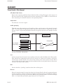
INTRODUCTION
System Information
INTRODUCTION
System Information
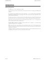
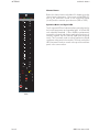
The 88RS is an ‘in-line’ monitor type console.
Each channel strip contains all the facilities necessary for multitrack recording, overdubbing and
mixdown.
The console has the powerful feature of split operation - i.e. the console can be operationally
divided into two halves (to the left and right of the master control panel) with independent status
control and split mix busses.
Surround sound is built in. This means that the I/O module pan pots have both LCR and LR (stereo)
pan laws and that there are dedicated surround mix busses, monitoring and metering features.
Mix busses, metering and monitoring are configured for stereo, LCRS, 5.1 or 7.1 in a single action
using switches on the central re-assign panel.
Standard 88RS consoles are capable of stereo, LCRS and 5.1 operation. 7.1 format mixing
requires the optional “SP” scoring panel.
88RS uses AMS Neve’s cross platform Encore automation system with a fully integrated recall
system for storing and recalling control positions. Encore and the recall system are fully described in
a separate user manual.
In addition to dynamic automation and recall, Encore assists in console configuration tasks such as
overdubbing. The console can also run manually without Encore.
Issue 3
88RS User Manual 1:1
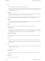
Power Up and Power Down Sequence
Power Up Procedure:
Power Up and Power Down Sequence
Power Up Procedure:
Switch the Encore PC on:
q There is a rocker on / off switch on the rear of the unit. Ensure this is set to '1'
q Press the red button on the front of the unit so it illuminates steady.
The PC will start to boot. Log on when required.
Switch the MCS unit on:
q Press the red switch on the front of the unit so it illuminates steady.
The MCS unit will start to boot.
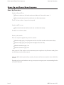
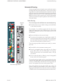
Power up the console:
There are 4 power supplies that power the console:
q Switch analog supply 1 on (this powers the Left side of the console and the centre section)
q Switch analog supply 2 on (this powers the Right side of the desk)
q Switch automation supply 1 on.
q Switch automation supply 2 on.
Lastly, press the 2 red switches on the automation power supplies so they illuminate steady (these
two switches power the fader motors).
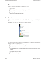
When the desk has been powered up correctly, the meters will exercise across the entire width of the
console.
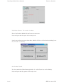
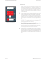
Depending on how your hardware is set up, you may now see a grey screen recommending that the
console be rebooted.
Issue 3
88RS User Manual 2:1
Power Up and Power Down Sequence
Power Up Procedure:
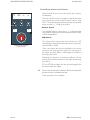
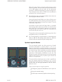
Click Reboot Console. The console will reboot.
When it has finished, double-click the Encore icon on screen.
Encore will open and the system will be ready to use.
If you do not see the grey screen shown above, double-click Servic eContorl on the desktop (it can
also be found in C:/Encore).
Select Reboot Console.
Once the console has finished booting double click on the Encore icon on the desktop.
Encore will open and they system will be ready to use.
Issue 3
88RS User Manual 2:2
Power Up and Power Down Sequence
Power Down Procedure
NB:
Failure to observe the correct power-up sequence can cause:
q Loss of audio
q The Reassign panel to not boot correctly (causing unpredictable audio on the busses)
q Inability to log onto automation
q General failure of the automation system
Power Down Procedure
Exit Encore. When asked "Do You Want To Close All Other Encore Components As Well?", click
Yes.
In Windows, go to 'Start / Turn Off Computer...' from the Start menu.
You will be informed when it is safe to turn the computer power off - do this by setting the rocker
switch on the back of the Encore unit to '0'.
q The red button on the front of the unit will extinguish.
q Turn off the MCS rack via the red button on the front.
q Turn off the fader motors (the two illuminated switches on the front of the automation power
supplies).
q Turn off both automation supplies.
q Turn off both console supplies.
Issue 3
88RS User Manual 2:3
Power Up and Power Down Sequence
Power Down Procedure
NB:
Failure to observe the correct power-down sequence can cause:
q Mechanical damage to the faders.
q Catastrophic failure of the Operating System.
Issue 3
88RS User Manual 2:4
CONSOLE CONFIGURATION
Power Down Procedure
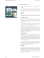
CONSOLE CONFIGURATION
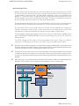
Signal flow through the console can be tailored for recording, mixdown and overdub tasks using
central master controls in conjunction with local channel switches. This section of the manual
outlines the basic configurations.
Two distinct signal paths are processed by each input module.
The channel path handles input sources during recording and tape playback during mixdown.
The monitor path is used primarily for monitoring multitrack sends and returns when recording and
for effects sends or returns during mixdown.
The monitoring path can also provide additional tape inputs for large mixdown operations.
The various I/O module sections can be switched between the two paths, allowing the operator to
configure each path with the optimum processing.
Input selection and output routing for the I/O module paths are normally determined by console
master status controls.
Issue 3
88RS User Manual 2:5
CONSOLE CONFIGURATION
Multitrack Recording
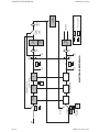
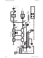
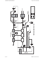
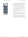
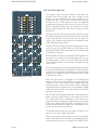
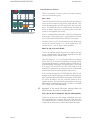
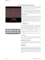
Multitrack Recording
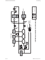
Input mic or line A signals are fed via the channel path and large fader to the multitrack routing
matrix.
The inputs can be processed using the high and low pass filters, equaliser and dynamics units.
The equaliser is normally in a post-dynamics position in the signal paths but can be switched to be
pre-dynamics.
The channel path can be routed directly to the track send of the same number or routed to the
multitrack busses to form part of an audio subgroup.
An input channel can also be used as a group output channel by pressing the GRP button, allowing
EQ and other processing to be applied to the group output to the track.
The track level control provides simple level adjustment for the track send.
Monitoring of either the multitrack sends or returns, or a mix of both is possible with switching
performed on a local or master basis, controlled from the monitor section.
The high and low pass filters, equaliser and dynamics can be switched to the monitor path with the
switches next to the small fader on the I/O module, and in a similar way the auxiliaries may be
configured in the monitor path, prefade, precut for cue sends to the studio or postfade for monitor
reverb sends.
The small fader is usually configured for monitoring when recording but this role can be swapped
with the large fader locally or on a master basis from the monitor section.
The monitor signal can be panned and routed via the main mix bus routing matrix to the main mix
outputs.
Issue 3
88RS User Manual 2:6
MIC
Issue 3
TAPE
AND TOGGLED GRP
LOCALLY BY TAPE
GRP
MT SEND
MT RETURN
GRP
FILTERS
PRE
DYN
EQ
AUX
AUX
CUT
CUT
SMALL
FADER
LARGE
FADER
MULTITRACK RECORDING
MONITOR PATH
DYN
CHANNEL PATH
AUX
AUX
PAN
PAN
Switch Out
Switch In
MAIN
MIX
ROUTING
MAIN
MIX
ROUTE
MT
MATRIX
DIR
= I/O Module Switch
= Master Control Switch
REASSIGN
MULTITRACK
TAPE
MACHINE
TRACK
LEVEL
CONSOLE CONFIGURATION
Multitrack Recording
88RS User Manual 2:7
CONSOLE CONFIGURATION
Mixdown
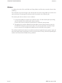
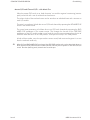
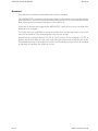
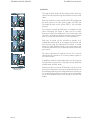
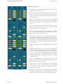
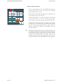
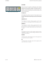
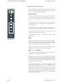
Mixdown
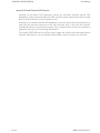
In mixdown the roles of the small fader and large faders are effectively reversed to those when
recording.
The multitrack returns are brought to the channel path and via the large fader are routed to the
main mix busses. Processing and auxiliary sends are normally in the channel path.
The monitor path has two distinct uses in mixdown:
1. It accepts secondary mix inputs such as effects returns. Unused channel path processing
can be switched to the monitor path where necessary.
Access to the main mix outputs is provided on the multitrack routing matrix.
2. The path can be used for additional pre/post-fader channel effects sends by using the
CH.OP/CH.IP (channel output/input) switch. The monitor path fader controls the send
level to any one of the 48 groups available from the multitrack routing matrix.
The auxiliary sends from the channel can also be routed to the multitrack routing matrix in place of
the monitor path signal using buttons in the aux section of the I/O strip, effectively expanding the
number of auxiliary sends available during mixdown.
Issue 3
88RS User Manual 2:8
Issue 3
LED LIT RED - CHANNEL O/P POST FADE
LED LIT GREEN - CHANNEL I/P PRE FADER POST EQ
CH.OP
CH.IP
Non Locking
Tri State
LED NOT LIT - MIX/EFFECTS RETURN INPUTS
CH.OP
CH.IP
OFF
MIX/EFFECTS RETURN
INPUTS
FROM PATCHBAY
MULTITRACK
TAPE
MACHINE
FILTERS
PRE
DYN
EQ
CUT
CUT
AUX
AUX
SMALL
FADER
LARGE
FADER
AUX
AUX
MIXDOWN CONFIGURATION
MONITOR PATH
DYN
CHANNEL PATH
PAN
MAIN
MIX
ROUTING
MAIN
MIX
ROUTE
MT
MATRIX
Switch Out
Switch In
FEED FROM
AUX
PAN
MTK
= I/O Module Switch
Non Locking
= Master Control Switch
REASSIGN
GROUP OUTPUTS
FOR AUX SENDS
CONSOLE CONFIGURATION
Mixdown
88RS User Manual 2:9
CONSOLE CONFIGURATION
Overdubbing
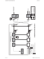
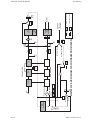
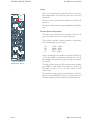
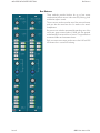
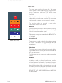
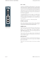
Overdubbing
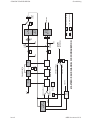
The console has a sophisticated monitoring and cue send system for tracklaying and overdubbing
which allows the engineer total monitoring freedom in the control room whilst maintaining the
correct cue sends to the studio. The configuration is controlled by a combination of master switches,
local channel switches and mode selection within Encore.
The artists’ headphones are normally fed from the console cue outputs, which in turn are normally
fed from auxes in the monitor path, pre-fader. In this description of overdubbing, the terms cue
output and pre-fade monitor auxiliary are interchangeable.
Group/Tape and Channel Overdub Operation
The Multitrack Monitor pushbuttons (GRP and TAPE) on the Master panel switch the inputs to the
console’s monitor paths on a master basis from multitrack send (GRP) to multitrack return (TAPE).
Additionally, the monitor path source on any channel can be toggled locally between GRP and
TAPE using the GRP/TAPE pushbutton on the I/O module.
Input channels switched to O/D send the console output (track send) to the cues feeding the studio
headphones.
The backing track channels (those without channel O/D selected) send the multitrack return to the
cues.
These basic modes are modified by additional centre section master switches and Encore status.
-
Issue 3
Control of tape machine track arming, either parallel or serial is an option.
88RS User Manual 2:10
MULTITRACK
TAPE
MACHINE
Issue 3
TAPE
TAPE
GRP
GRP
MIC
GRP
TAPE
PRE
DYN
MONITOR PATH
DYN
EQ
CUT
BACKING TRACKS
O/D
O/D
OVERDUB TRACKS
AUX
CUT
AUX
AUX
MONITOR
PRE FADE
AUXILIARIES
SMALL
FADER
LARGE
FADER
PAN
GRP/TAPE AND CHANNEL O/D CONFIGURATION
TOGGLED
LOCALLY BY
FILTERS
CHANNEL PATH
Switch Out
Switch In
PAN
MAIN
MIX
ROUTING
MAIN
MIX
ROUTE
MT
MATRIX
TRACK
LEVEL
= I/O Module Switch
= Master Control Switch
REASSIGN
DIR
CONSOLE CONFIGURATION
Overdubbing
88RS User Manual 2:11
CONSOLE CONFIGURATION
Overdubbing
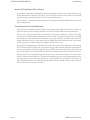
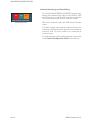
Master O/D and Channel O/D Function
Switching on the Master O/D pushbutton cancels any previously operated channel O/D
pushbuttons, and puts all monitor paths into TAPE, so that the control room monitors and cue sends
from all channels are both on the multitrack returns.
Switching on an individual channel O/D pushbutton causes the control room monitoring and cue
send from that particular channel to be fed from multitrack send. It also arms the channel’s
corresponding track on the multitrack machine (if the console has been wired to the multitrack to
support this function) See Track Arming details below.
The channel GRP/TAPE switch can still be used to toggle the control room monitoring between
multitrack send and return on an individual channel basis, while cues remain on track send.
Issue 3
88RS User Manual 2:12
Issue 3
GRP
MULTITRACK
TAPE
MACHINE
TRACK
ARM
LOGIC
O/D
ENCORE
GRP
TAPE
FILTERS
PRE
DYN
BACKING TRACKS
OVERDUB TRACKS
MONITOR PATH
DYN
EQ
O/D
AUX
CUT
CUT
AUX
AUX
MONITOR
PRE FADE
AUXILIARIES
SMALL
FADER
LARGE
FADER
MASTER O/D AND CHANNEL O/D CONFIGURATION
TOGGLED
LOCALLY BY
BACKING TRACKS
OVERDUB TRACKS
MIC
CHANNEL PATH
PAN
Switch Out
Switch In
PAN
MAIN
MIX
ROUTING
MAIN
MIX
ROUTE
MT
MATRIX
TRACK
LEVEL
= I/O Module Switch
= Master Control Switch
REASSIGN
DIR
CONSOLE CONFIGURATION
Overdubbing
88RS User Manual 2:13
CONSOLE CONFIGURATION
Overdubbing
Master O/D and Preset O/D via Encore
An alternative method for performing single track overdubs is to preset the overdub channel using
Encore instead of the Channel O/D switch. The Channel O/D switch is then used to enter Record
mode directly for individual tracks. See Track Arming details below.
The “mixed cue” configurations described on the next pages are valid for both Encore and manual
O/D configurations.
Track Arming with the Overdub button
Track arming commands are either initiated from or passed through Encore from the console, so
Encore must be up and running for this feature to work. The master O/D switch must also be on.
There are two ways of putting tracks into record on a multitrack: preselect the tracks to record by
“arming” them and then drop the transport into record mode. This puts all armed tracks into record
simultaneously. Alternatively put the transport into record mode first and drop each track into
record individually using its track arming switch. 88RS allows both methods to be used without
interfering with the audio routing for the engineer’s and artists’ cues.
Selecting O/D tracks using the channel O/D switches is the equivalent of doing the track arming
first. The selected O/D switches set up the audio routing and illuminate dimly until the transport is
put into record mode, at which point all the selected O/D switches illuminate fully as their tracks go
into record together. Non-selected O/D switches remain dark and their tracks don’t go into record.
Selecting O/D tracks using Encore’s preset screen sets up the audio routing for the cues for these
tracks, but does not arm the tracks. This allows the transport to be put into record mode without the
tracks going into record. When the transport is in record mode, the preset O/D switches flash to
warn that pressing them now will drop the associated tracks into record. O/D switches not preset
will not flash and will not go into record.
Issue 3
88RS User Manual 2:14
Issue 3
RECORD
DC
TALLIES
FROM
REC
AND
PLAY
MULTITRACK
TAPE
MACHINE
OD
TRIM
TOGGLED
LOCALLY BY
O/D
GRP
TAPE
BACKING TRACKS
OVERDUB TRACKS
MIC
PRE
DYN
MONITOR PATH
DYN
ART
MIXED
CUE
EQ
AUX
CUES
POST
EQ
CUT
CUT
SMALL
FADER
LARGE
FADER
PAN
Switch Out
Switch In
OVERDUB TRACKS
PRESET IN ENCORE
TRACK
LEVEL
2T OUTPUTS
DIR
= I/O Module Switch
= Master Control Switch
MONITOR
PRE FADE
AUXILIARIES
4T
ROUTING
MT
MATRIX
BACKING TRACKS
AUX
AUX
PAN
MASTER O/D AND PRESET O/D CONFIGURATION
FILTERS
CHANNEL PATH
CONSOLE CONFIGURATION
Overdubbing
88RS User Manual 2:15
CONSOLE CONFIGURATION
Overdubbing
Master O/D and Channel O/D - with Mixed Cue
When the master O/D switch is on, both the artists’ cue and the engineer’s monitoring (monitor
path) can be fed with a mix of multitrack send and return.
The relative levels of the send and return can be varied on an individual basis with a trimmer on
each I/O module.
The artists’ cue sends are fed with this mix on O/D track channels by operating the ART MIXED CUE
switch in the master section.
The control room monitoring is fed from this mix on O/D track channels by operating the ENG
MIXED CUE pushbutton in the master section. This changes the function of the GRP/TAPE
pushbutton on the I/O module so that it now feeds the control room monitoring from the mix of
multitrack send and return in the GRP position - and tape return only in the TAPE position.
In both of these modes, once the tape machine enters record, both artist and engineer’s cue are
from the multitrack send only.
-
Issue 3
When O/D and ENG MIXED CUE are selected, the GRP/TAPE switches only work as described above on
those channels locally selected to be overdub channels, either by Encore presets or with the local O/D
switch. The other (backing track) channels are forced to tape.
88RS User Manual 2:16
Issue 3
DC
TALLIES
FROM
REC
AND
PLAY
READY
O/D
ENG
MIXED
CUE
TRIM
+
+
GRP
TAPE
BACKING TRACKS
(TAPE)
OVERDUB TRACKS
(GRP)
FILTERS
PRE
DYN
MIX
MONITOR PATH
DYN
ART
MIXED
CUE
EQ
CUT
SMALL
FADER
OVERDUB TRACKS
BACKING TRACKS
AUX
CUT
LARGE
FADER
O/D
AUX
AUX
PAN
Switch Out
TRACK
LEVEL
= I/O Module Switch
= Master Control Switch
REASSIGN
DIR
MONITOR
PRE FADE
AUXILIARIES
MAIN
MIX
ROUTING
MAIN
MIX
ROUTE
MT
MATRIX
Switch In
PAN
MASTER O/D AND CHANNEL O/D CONFIGURATION MIXED CUE
PAD
RECORD
MULTITRACK
TAPE
MACHINE
MIC
CHANNEL PATH
CONSOLE CONFIGURATION
Overdubbing
88RS User Manual 2:17
CONSOLE CONFIGURATION
Tape and Cues Post EQ
Tape and Cues Post EQ
The backing track cues can be assigned to a 'follow monitor' condition using CUES POST EQ so
that any monitor filtering, equalisation and dynamics processing are also heard on the cues. The
cues cannot be set post EQ on monitor paths set to GROUP.
Issue 3
88RS User Manual 2:18
Issue 3
DC
TALLIES
FROM
REC
AND
PLAY
MULTITRACK
TAPE
MACHINE
TAPE
TRIM
MIC
FILTERS
PRE
DYN
EQ
AUX
CUES
POST
EQ
CUT
CUT
TAPE AND CUES POST EQ
MONITOR PATH
DYN
CHANNEL PATH
O/D
SMALL
FADER
LARGE
FADER
AUX
AUX
PAN
Switch Out
Switch In
PAN
TRACK
LEVEL
= I/O Module Switch
= Master Control Switch
REASSIGN
DIR
MONITOR
PRE FADE
AUXILIARIES
MAIN
MIX
ROUTING
MAIN
MIX
ROUTE
MT
MATRIX
CONSOLE CONFIGURATION
Tape and Cues Post EQ
88RS User Manual 2:19
CONSOLE CONFIGURATION
Broadcast
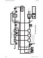
Broadcast
This mode allows simultaneous broadcast and multitrack recording.
When BROADCAST is pressed the monitor path signals are taken from the channel paths, prefade,
post-equalisation. This can be further enhanced by selecting local “CH.IP” on a channel by channel
basis, allowing for processed pre fade inputs to be mixed to air.
Fader swap is automatically engaged when BROADCAST is selected and can be cancelled whilst
broadcast is still engaged.
This facility allows the small fader to control the multitrack mix and the large fader to control the
main mix for broadcast. This method optimises the level sent to tape.
Alternatively the individual channels’ CH.OP & CH.IP switches can be engaged in CH.OP to
produce post channel fader, pre-pan track sends using the monitor fader to trim the track sends.
This method records inputs at roughly the level they were broadcast at, so the mix can be recreated
by replaying the multitrack with faders set at unity.
Issue 3
88RS User Manual 2:20
Issue 3
GRP
OD
TAPE
MT SEND
MT
RETURN
BROAD
CAST
MIC
PRE
DYN
LED LIT RED - CHANNEL O/P POST FADE
LED LIT GREEN - CHANNEL I/P PRE FADE POST EQ
CH.IP
EQ
AUX
AUX
CUT
CUT
BROADCAST MODE
LED NOT LIT - MIX/EFFECTS RETURN INPUTS
MONITOR PATH
OFF
Non Locking
Tri State
DYN
CH.OP
CH.OP
CH.IP
GRP
FILTERS
CHANNEL PATH
SMALL
FADER
LARGE
FADER
AUX
AUX
PAN
Switch Out
Switch In
PAN
4T
ROUTING
MT
MATRIX
MULTITRACK
TAPE
MACHINE
TRACK
LEVEL
= I/O Module Switch
Non Locking
= Master Control Switch
2T OUTPUTS
DIR
CONSOLE CONFIGURATION
Broadcast
88RS User Manual 2:21
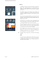
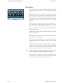
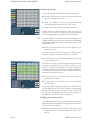
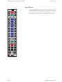
THE 88RS CONSOLE SURFACE
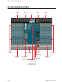
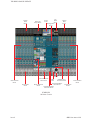
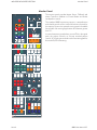
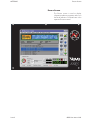
THE 88RS CONSOLE SURFACE
Channel
Meter
Section
Monitor 6T
Output Meters
Aux
Meter
Section
Encore
Screen
Trackball
Monitor & Facilities
Fader Section
Channel Module
Section
Channel
Meter
Section
Channel Module
Section
MCS & Dynamic
Automation Section
Channel Fader
Section
Monitor & Facilities
Section
Reassign Matrix
Section
Encore Global Master
Events Section
Channel Fader
Section
Encore Global Master
Automation Section
Standard 6T 88RS
24 Fader Console
Issue 3
88RS User Manual 3:1
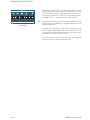
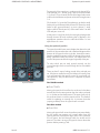
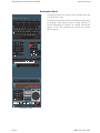
THE 88RS CONSOLE SURFACE
Channel
Meter
Section
Monitor 8T
Output Meters
Aux
Meter
Section
Reassign Matrix
Section
Encore
Screen
Channel
Meter
Section
Trackball
Monitor & Facilities
Fader Section
Channel Module
Section
Channel Fader
Section
MDE
Fader
MCS & Dynamic
Automation Section
Encore Global Master
Monitor & Facilities
Events Section
Section
Encore Global Master
Automation Section
Channel Module
Section
Channel Fader
Section
8T 88RS SP2
24 Fader Console
Issue 3
88RS User Manual 3:2
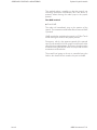
THE 88RS CONSOLE SURFACE
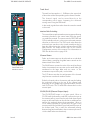
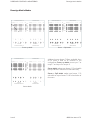
The 88RS Channel Module
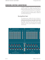
The 88RS Channel Module
1/25
2/26
3/27
4/28
5/29
6/30
7/31
8/32
9/33
10/34
11/35
12/36
13/37
14/38
15/39
16/40
17/41
18/42
19/43
20/44
21/45
22/46
23/47
24/48
1-24
M
T
K
1-2
25-48
3-4
5-6
7-8
9-10
LS/RS
LCR
C
NAR
ST
PAN
L
R
Channel Module
Multitrack Routing
section
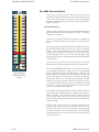
There are two versions of the channel strip, one with an
integral microphone amplifier, and one with dual line level
inputs that will support an optional remote microphone
amplifier. Apart from the input section, both versions have
identical facilities.
Multitrack Routing
At the top of the module there are the routing buttons for the
48 multitrack busses, the 4 stereo plus LS/RS (9-10) and the
LCR main mix busses.
Using the 1-24 and 25-48 selector buttons it is possible to
route to multitrack busses in the range 1-24, or 25-48, or
both.
Switching the pan control in will allow the multitrack send to
be panned between odd (left) and even (right) numbered
tracks. It also enables panning to the main mix busses.
Without the pan control, the output is sent equally to left
(centre) and right. When in circuit, the control automatically
delivers an L-R pan law to stereo busses and an LCR pan law
to LCR busses.
How the main mix busses are actually used in surround
format mixing is determined by the central re-assign panel.
The unique NARROW/ST button is a tri state switch which
only works when the pan is switched on. In its un-operated
state the LCR pan law has a wide divergence. However, with
the first press of the button the LED indicator will light red
and the LCR pan law will change to a narrow divergence.
Pressing the button for a second time will make the LED
indicator turn green and the L and R of the LCR bus will be
fed with the ST pan so as to allow the operator to create
“phantom” centres. Pressing the button a third time will
return to wide divergence (LED off).
The multitrack routing is fed from either the channel path or
the monitor path, depending on the mode of the channel.
When recording, the multitrack routing comes from the
channel path, but when mixing the source is normally the
monitor path, allowing the busses to be used as additional
auxiliary sends.
MTK switches in the auxiliary send section also allow aux
sends to be diverted to the multitrack busses during
mixdown. This does not affect the monitor path routing to
the main mix busses, so the monitor paths can still be used
as additional mix inputs while the auxes are routed to the
multitrack busses.
Issue 3
88RS User Manual 3:3
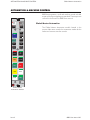
THE 88RS CONSOLE SURFACE
LINE
0
gain
Input Selector
+15
-15
C/O
70
50
GRP
The 88RS Channel Module
20pull
ph
0FF
30
40 MIC
-20
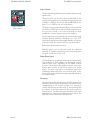
Channel Module
Input section
The mic amp design offers low noise and low distortion at all
signal levels.
The gains of the mic and line inputs are adjusted on two
continuously variable rotary controls providing a total range
of 0dB to +70dB (in conjunction with -20dB PAD) for mic
and -15 to +15dB for line with centre detent.
The dual line input module has two LEDs to indicate whether
the LINE A or LINE B input is selected. Both modules have a
mic input trim control, in the case of the dual line input
module this is for the optional remote mic amplifier.
Mic/line switching is controlled by the central mode control
switches (Record, Mixdown, Broadcast etc.). The C/O
switch allows the selection to be toggled locally. Its indicator
illuminates when the channel input is in the Mic position.
Both inputs can be phase reversed.
Phantom power can be selected on/off on individual
channels. The default is phantom power on, but pulling the
mic gain control out will turn it off.
Fader Direct Input
A line level input (e.g. from specialist external channel inputs
such as the Neve 1081 module) can be brought into the
channel fader input, bypassing all the 88RS channel
functions. This is done under computer control - refer to the
System Menu section of the Encore manual for further
details. The direct input point is immediately before the
small/large fader swap point in the channel path, so the
direct input may be to the small or large fader depending on
the channel mode.
Grouping
For patch-free audio sub-grouping, the GRP group switch
allows the channel input to be switched to the multitrack bus
corresponding to the channel number. For example if
several channels are routed to track 6, then pressing GRP
on channel 6 will make channel 6 the group master for
these channels. This allows all inputs routed to track 6 to be
processed as a channel signal before being re-routed. The
GRP switch over-rides the mic/line selection.
Issue 3
88RS User Manual 3:4
THE 88RS CONSOLE SURFACE
The 88RS Channel Module
Input Filters
kHz 7.5
18
8
13
pull
FILT
315
31.5
Hz
50
10
240
9
150
80
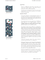
Channel Module
Input Filter section
These are 12dB/octave high and low pass filters, with
continuously variable frequency ranges from 31.5Hz to
315Hz and 7.5kHz to 18kHz respectively.
The filters can be switched into the channel or monitor path
independently of the EQ by pulling out the relevant
frequency control knob.
Dynamics Control
Full limiter/compressor and gate/expander facilities are
available (each of which can be individually switched in or
out of circuit). The expander/gate uses the left hand side
controls of the section and the controls for the
compressor/limiter are on the right.
KEY
L/C
SC-EQ
EXP
HYST 25
GAIN
0
5 30
20
6
10 24
THR
-25 18
15
15
12
THR
pull
20 HN
-17 -10
7
pull
-40
14
-10 -4
0
8
2
pull
-20
30
20
3
50
10
0
pull
FAST
pull
INV
.01
RGE
0.2
REL
GATE
5
60 2
1
lim
RAT
pull
FAST
0.2
.01
3s
REL AUTO
3s
Channel Module
Dynamics section
The expander/gate has rotary controls for a 0-60dB gate
depth range, a +15 to -65dB threshold (using the
integrated -40dB switch), release time from 10ms to 3s, a
switchable attack time of 500ms (RGE knob in) or 50ms
(RGE knob pulled out) and variable hysteresis.
The hysteresis control sets the difference in threshold for
signals that are rising or falling in level. Signals that are
rising in level turn on when the level reaches the threshold
level plus the hysteresis value. Signals that are falling in level
turn off at the lower threshold level. Raising the threshold for
rising signals prevents noise turning the gate on, while
allowing a lower threshold for falling signals to prevent
reverb signal ‘tail’s being prematurely gated. For example,
if the threshold is set at - 50 and the hysteresis is set at 10,
the signal level would have to rise above -40dB before the
channel turns on and the channel would remain on until the
signal level fell below -50dB. The control allows up to 25dB
of hysteresis.
Turning the hysteresis control fully counter-clockwise
switches the gate off and the 2:1 expander on.
Pulling out the release control inverts the key (control) signal
to the gate, turning it into a “ducker”. This feature is
normally used with an external key. When gating, a signal
above threshold level on the key input allows signal to pass;
when ducking a signal above threshold level on the key
input causes the gain of the channel signal to be reduced by
the amount set on the depth (RGE) control.
Switches are provided for the external key input and for
inserting the EQ into the side-chain, for frequency
conscious gating or compression (eg de-essing). The
external key input is accessed from the patchbay.
Issue 3
88RS User Manual 3:5
THE 88RS CONSOLE SURFACE
The 88RS Channel Module
The limiter/compressor has rotary controls for release times
from 10ms to 3s, a +20 to -30dB threshold range, a ratio of
1:1 to limiting and up to 30dB of gain make-up. The
compressor has soft knee characteristics as standard with
hard knee available by pulling out the gain control. Attack
time is program dependent, ranging from 3ms to 7ms, or
1ms to 7ms if the ratio control is pulled out (fast).
KEY
L/C
SC-EQ
EXP
HYST 25
GAIN
0
5 30
20
6
10 24
THR
-25 18
15
15
12
THR
pull
20 HN
-17 -10
7
0
pull
-40
8
2
pull
-20
30
20
50
10
3
RAT
0.2
REL
GATE
lim
pull
FAST
3s
.01
The LINK switch links the dynamics gain control with that of
the module located immediately to the right. This allows a
stereo input across two or more modules to compress/limit
to the same amount, maintaining the stereo image.
3s
REL AUTO
Channel Module
Dynamics section
Issue 3
Anti pumping and breathing circuitry allows the unit to
operate on the source musically whilst retaining absolute
control over the dynamic range.
5
2
pull 0 RGE 60
FAST
0.2
1
pull
INV
.01
The limiter/compressor release control has an end switch
for automatic programme dependent release. Turning the
release control fully clockwise (to 3S) switches to a triple
time-constant, programme dependent release time.
14
-10 -4
-
As stated the release time can be set to a very fast 10ms release.
This will only be suitable for certain percussive instruments
themselves having a fast decay and should not be applied for
all slow decay sources as undesirable results can be obtained.
88RS User Manual 3:6
THE 88RS CONSOLE SURFACE
The 88RS Channel Module
Auxiliaries
PAN
PRE
8
MTK
ON
Each aux send has its own individual On/Off switch (press
the level control in for ON, press it again for OFF) and
Pre-fade/Post-fade switch (press PRE in for pre-fader
position).
PRE
7
ON
5-6
ST
MTK
7-8
PAN
PRE
6
MTK
ON
PRE
5
ON
PAN
4
ON
PRE
3
ON
1-2
ST
MTK
3-4
PAN
PRE
2
MTK
ON
PRE
1
ON
MTK
Channel Module
AUX section
Issue 3
The channel pre-fade pick-off point is arranged so that
when tracklaying the signal is taken pre-cut to allow
destructive solos to be performed in the control room and
still retain cue sends. In Mixdown mode the signal is taken
post-cut so that the effects send is cut with the source.
MTK
PRE
MTK
The eight auxiliary sends can be configured into either the
channel or monitor path using the switches next to the small
fader.
Each pair of sends can be switched to operate as 2
independent mono sends, or as a stereo aux with level and
pan controls using the numbered ST switches. In stereo
mode, the odd numbered knob is the level control and
on/off switch while the even numbered control becomes the
pan control.
For correct operation of a stereo aux bus, the aux pair
should also be switched to ST on the aux master control in
the centre section.
In Mixdown mode the small fader output can be routed to
the multitrack routing matrix - allowing as many as 48 fully
mixable extra auxiliary sends.
Alternatively the aux section MTK buttons can be used to
divert one or more of the auxes to the multitrack busses with
the advantage that they have independent level control over
the contributions and that the monitor path is still available
to use as an additional input with routing to the main mix
busses.
88RS User Manual 3:7
THE 88RS CONSOLE SURFACE
The 88RS Channel Module
Inserts
PREQ
18
3.2
13
kHz
INS
1.5
8
PREDYN
5.3
Inserts can be positioned in either the channel or monitor
path independently of the EQ using the switch next to the
small fader.
The insert can be switched post-equaliser or pre-EQ and
dynamics .
HI-Q
9.0
0.8
3.7
2.4
6.0
kHz
The insertion will provide an output regardless of the INS key
state.
1.4
Formant Spectrum Equalisers
The unique sound of AMS Neve equalisers is the result of
years of research and extensive studio experience.
Q
2k
120
330
1.4
Hz
940
Q
570
HI-Q
440
73
300
Hz
33
200
The equaliser provides 4-band parametric equalisation,
with overlapping frequency ranges.
HF
M2
M1
LF
1.5kHz - 18kHz
0.8kHz - 9kHz
120Hz - 2kHz
33Hz - 440Hz
120
EQ
Channel Module
Equalisation section
The two mid-bands have variable controls for Q (from 0.4
to 10), gain (20dB cut and boost) and frequency. The Q
also changes automatically with gain (as gain is increased,
so is the Q).
The high and low frequency EQ controls provide variable
gain (20dB cut and boost) and frequency controls with
switchable Q (either 0.7 or 2) and a peak or shelf
characteristic.
The equaliser section can be switched before or after the
dynamics section (PRE-DYN switch). It can be used in the
Channel or Monitor path (switches in the small fader area).
Issue 3
88RS User Manual 3:8
THE 88RS CONSOLE SURFACE
The 88RS Channel Module
Track Send
The track level trim applies +/- 10dB trim to the output level
of the multitrack bus corresponding to the channel number.
TRACK
DIR
GRP
TAPE
The channel signal can be routed directly to the
corresponding track output, bypassing the multitrack
routing matrix using the DIR button.
O/D
TO MTK
C/O M
O
D
SWAP E
10
CH.0P
CH. I P
5
DYN
0
INS M
O
N
5
EQU I
T
O
10
FILT R
20
30
40
7-8
A
U
X
5-6
3-4
1-2
RET
SOLO
CUT
Channel Module
Small Fader and
Mixdown section
P
A
T
H
In this mode, signals from other channels cannot be routed
to this track.
Monitor Path Switching
The console has a sophisticated monitoring system allowing
monitoring freedom in the control room while the correct
cue sends are retained. The system uses the GRP/TAPE and
O/D (overdub) switches in conjunction with master monitor
selection to achieve this. The O/D switch also allows the
multitrack tape machine to be record armed/punched in
from the channel strip plus a further enhancement of GRP
ARM facilities. For further details refer to the Console
Configuration section of this manual. For information on
GRP Arm facilities refer to page 5:18.
Channel Status
Fader and status swaps can be achieved on an individual
channel basis, overriding the global status controls on the
Master Mode Select Panel.
The SWAP button reverses the roles of the small and large
faders. Automation that was written on the small fader gets
transferred to the large fader and vice versa. i.e. the
automation stays with the path, not the fader.
The C/O button switches the configuration of the channel
strip between record and mixdown modes.
Either the channel path or the monitor path may be feeding
the multitrack routing at the top of the channel strip
depending on the global status (record/mixdown) and the
local C/O switch. The TO MTK LED indicates when it is the
monitor path.
CH.OP/CH.IP (Channel Output/Input)
The CH.OP/CH.IP button is a tri state switch. When in
CH.OP mode (indicated by a red LED) it allows the input to
the monitor path to come from the post-fade channel path
output so the small fader can be used as an additional aux
send to the multitrack busses during mixdown. When in
CH.IP mode (indicated by a green LED) the input to the
monitor path will be fed from the pre fade post EQ output of
the channel path. This is useful for automated panning
between large and small faders, where a mono input source
is fed to both faders simultaneously.
Issue 3
88RS User Manual 3:9
THE 88RS CONSOLE SURFACE
The 88RS Channel Module
Small fader
TRACK
The small fader uses a Penny and Giles conductive plastic
moving fader and is automated in the same way as the large
fader. The small fader is normally in the monitor path, but
can be swapped with the large fader.
DIR
GRP
TAPE
O/D
Monitor Path Selectors
TO MTK
C/O
SWAP
10
M
O
D
E
CH.0P
CH. I P
5
DYN
0
INS M
5
EQU
10
FILT
20
30
P
A
T
H
7-8
P+G
5-6
A
U
X
P+G
40
O
N
I
T
O
R
3-4
1-2
R
E
C
SEL
1-2
3-4
5-6
7-8
9-10
LS/RS
LCR
SF
Mixdown Output Selection
At the bottom of the channel strip are the routing buttons for
the main mix busses. The pan control creates both LCR and
L-R pan laws for the different bus types. As well as an on/off
switch, the pan control can be set to give the signal a
WIDE/NARROW width or “Phantom” centres using the NAR
ST button in the LCR field.
NAR
ST
C
PAN
L
SOLO
R
A
B
CUT
Channel Module
Small fader and main
fader routing sections
Issue 3
The RET switch is a quad state button which allows the
channel to be isolated from the channel and monitor solo
mutes, therefore the channel can be used as a rev return
input. LED indication shows the 4 states; Off: no isolation,
Red: LF isolate, Green: SF isolate, Yellow: both LF & SF
isolate.
Are used to set the automation modes for the channel
switches. Refer to the ‘Automated Channel Controls’
section of the Encore manual for further details.
CUT
MODE
Channel/Monitor Safe
Mode & Sel
RET
SOLO
The MONITOR PATH switches next to the small fader are
used to assign the module’s processing elements such as
the EQ, dynamics and auxiliary sends to the monitor signal
path.
Solo and Cut Facilities
The console has a sophisticated solo system with selectable
momentary, interlocking and latching action push-buttons
performing either in-place solo, or PFL or Surround AFL type
solos.
Cuts and Solos are described fully in the following chapter
of this manual.
88RS User Manual 3:10
THE 88RS CONSOLE SURFACE
Channel Fader Module
Channel Fader Module
ALL
A Penny & Giles moving fader with associated discreet
automation controls.
SEL
MUTE
MODE
SMALL
FADER
SF
MUTE
LF
MUTE
MUTE
MODE
10
Mutes
The two Mute Buttons are for the large and small faders.
Unlike the Cut buttons in the channel module, these mutes
are automated.
A full description of the automation modes and operation of
the other controls is given in the Encore manual.
5
0
GLIDE
5
REC
10
PLAY
20
TRIM
30
ISOLATE
40
Channel Fader
Issue 3
88RS User Manual 3:11
SOLO & MASTER CUT SYSTEM
SOLO & MASTER CUT SYSTEM
The 88RS has comprehensive solo and cut facilities with
operation affected by switches in the channel module and in
the centre section.
CHAN
SAFE
MON
SAFE
PFL
LATCH
I/L
RESET
CUT
A
CUT
B
SOLO
LINK
SOLO + CUT
Centre Section
Solo & Cut
The channel and monitor paths of the console’s channel
modules have independent SOLO and CUT systems, unless
the centre section SOLO LINK is selected.
The operation of the solo is linked to the path, not the fader.
If a fader swap is performed on a channel, the solo and cut
functions move with the path to the other fader. For
example, if only one strip’s faders are swapped and the
large fader SOLO is pressed on that strip when the console
is in solo cut mode, the small fader cut switches will be
activated on all the other channels.
Solo System
Latching, momentary or interlocking solo
The action of the channel module solo switches can be
latching, momentary, or interlocked.
A
SOLO
B
CUT
Channel Module
Solo and Cut
switches
Latching Solo allows solo to be turned on and off on
individual strips. After the first solo has been pressed, it
remains on till de-selected. Other channels can be included
in the solo at the same time, independently of each other.
Interlocking Solo causes each solo selection to de-select
any previous selection so that only one path is soloed at a
time. To solo multiple channels in interlock mode, hold
down the first solo switch while pressing other solo switches.
The selection will remain soloed when the first switch is
released, until another solo switch or the centre section
RESET switch is pressed.
Momentary Solo causes the solo switch to only operate for
as long as they are held down. To enable momentary
operation, press either the LATCH or the I/L switch.
Multiple paths can be monitored simultaneously in
momentary mode by holding down the first solo switch
pressed while pressing additional solo switches.
The selection will remain active until the SOLO
key/push-button being held down is released.
Issue 3
88RS User Manual 4:1
SOLO & MASTER CUT SYSTEM
Solo System
Cut or Monitor Solo (with AFL or PFL)
CHAN
SAFE
MON
SAFE
PFL
LATCH
I/L
RESET
CUT
A
CUT
B
SOLO
LINK
SOLO + CUT
Centre Section
Solo & Cut
The systems are normally in ‘cut solo’ mode, unless the tape
machine is in record or a safe mode has been selected. Cut
solo cuts all channel or all monitor paths (or both if SOLO
LINK is enabled) except for the path being soloed. This
affects what is going to the mix busses as well as what is
heard in the monitoring.
The safe mode is a “monitor solo”. The system (normally)
provides positional AFL (after-fader listen) solo unless PFL
(pre-fade listen) is selected. Monitor solo only affects the
control room monitoring, not the signal going to the mix
busses.
Solo in Place
Cut Solo does not affect the monitoring system, so naturally
it leaves the solo in place, ie the source is heard as it is
panned within the stereo or surround panorama.
Monitor solo switches the monitoring to dedicated surround
AFL or PFL mix busses. With this unique system if a channel is
routed to the ST busses then the AFL will be heard on the L
and R speakers. If a channel is routed to the LCR bus then
the AFL will be heard on the LCR speakers. Lastly if a
channel is routed to the LS RS (9-10) busses then AFL will be
heard on the surround loudspeakers. When AFL is operated
the LFE (LE RE) speakers will be muted.
Due to the diverse nature of surround AFL monitoring an
AFL SWAP switch in the monitor section will switch the AFL LS
and RS busses to the left and right speakers so that signals
intended for the surround speakers can be auditioned in the
front loudspeakers for quick checking.
Cut Solo Indication
If a signal on the large fader is cut due to a solo being
activated elsewhere, the CUT key will illuminate to half
brightness to indicate cut solo.
The LED for the small fader CUT push-button does not have
a half-brightness mode for cut solo. It will illuminate in cut
solo the same as it does when pressed individually.
Combining the monitor and channel solo systems
Pressing the SOLO LINK key in the Monitor Panel connects
the solo systems so that pressing any solo switch will mute all
other non-soloed channel and monitor paths when in cut
solo mode, except those with the RET button engaged.
Issue 3
88RS User Manual 4:2
SOLO & MASTER CUT SYSTEM
Solo System
Cut Solo Protection
TRACK
Pressing the RET switch in the small fader section of the
channel strip prevents both the channel path and monitor
path being cut when a cut solo is pressed anywhere on the
console. This makes the channel usable as a reverb return.
DIR
GRP
TAPE
O/D
TO MTK
C/O M
O
D
SWAP E
10
CH.0P
CH. I P
5
INS M
The monitor path is also protected against solo cuts when it
is being used as an audio group master, i.e. the GRP switch
is pressed in.
EQU I
Solo Cancellation
DYN
0
O
N
5
10
T
O
R
FILT
20
30
P
A
T
H
7-8
P+G
5-6
A
U
X
P+G
40
The function is quad state switchable to include either both
the channel and monitor path (indicated by a yellow LED),
the monitor path (indicated by a green LED) or the channel
path (indicated by a red LED).
Pressing the central RESET button will clear any solos that
are active.
3-4
1-2
RET
CUT
SOLO
R
E
C
MODE
SEL
1-2
3-4
5-6
7-8
9-10
LS/RS
LCR
SF
NAR
ST
C
PAN
L
SOLO
R
A
B
CUT
Small Fader Section
with RET switch
Issue 3
88RS User Manual 4:3
SOLO & MASTER CUT SYSTEM
Cut Grouping Facility
Cut Grouping Facility
A
B
The A/B toggle switch above the channel cut switches allow
the large fader cut switch to be included in either the A or B
cut groups.
CUT
SOLO
A/B CUT switch
in channel
Pressing the master CUT A or CUT B switches in the centre
section will mute any large fader that is switched to the A and
B mute groups respectively.
CHAN
SAFE
MON
SAFE
PFL
LATCH
I/L
RESET
CUT
A
CUT
B
SOLO
LINK
The master switches are electronically latched and are also
wired to external contacts on the console for possible
remote control. (Under external control the switches light to
half brightness). The master switches are also recallable.
Automated Mute Groups
SOLO + CUT
Master cut switches in
centre section
LF
MUTE
SF
MUTE
MUTE
MSTR
ALL
In addition to the cut groups described above, there is also
an automated A/B mute system. This system requires Encore
to be running (even for manual operation) and is enabled by
turning on the MUTE MSTR located on the Events panel,
together with the enable switch for either (or both) the small
fader or large fader mutes.
MODE LINK
RSI/
RESET
The mute system uses the same toggle switch on the module
as the A/B cut system to select each channel to the A or B
mute bus, or to neither. The mutes are then turned on/off
using the MUTE A and MUTE B buttons on the mute-master
Group faders. These switches will mute all the large faders
on channels selected to the A or B bus respectively if the LF
master is on and all the small faders on the busses if the SF
master is on.
SELECT
EV ENT S
Events Panel
ALL
SEL
MUTE
ALL
10
MUTE
MODE
5
MUTE
MODE
MUTE
MODE
MUTE
A
MUTE
B
MUTE
MUTE
MODE
0
GLIDE
REC
SEL
10
5
0
5
GLIDE
5
10
REC
10
PLAY
PLAY
20
TRIM
The mutes work on the fader circuitry, so if the faders are
swapped when muted (either locally or globally), the mute
will travel with the fader. However, the control is linked to
the path, so if the LF Mute enable is on and the faders are
swapped, operating the A or B group mute controls will
affect the small fader and vice versa.
20
Disabling the mute groups on the Events panel, either by
turning off the small or large fader mute enable or by turning
off the Mute Master will cancel the relevant set of mutes at
the same time as disabling the control. When the mute
groups are turned back on, they don’t automatically send
out either a mute set or a mute clear - the mutes are left as
they are until the controls on the group faders are used.
TRIM
30
ISOLATE
30
ISOLATE
40
40
The automation modes for the group mutes are set by using
the MODE key above the MUTE button on the group fader
panels in conjunction with the standard RSI automation
controls.
Group Fader Group Fader
Mute A
Mute B
Issue 3
88RS User Manual 4:4
MONITOR & FACILITIES SECTION
Oscillator and Signal level
MONITOR & FACILITIES SECTION
Oscillator and Signal level
Signal LED Threshold
SIG PRES
+26db
+4
+20
The signal threshold is the level at which the signal
indicators in the meter bridge come on. This indicator can
either be used as a signal present or a signal overload
indicator depending on the level set.
+6 +8
SIGNAL LED
THRESHOLD
SLATE
Oscillator Panel
The oscillator can be switched to frequencies of 40Hz,
100Hz, 400Hz, 1kHz, 4kHz, 10kHz and 15kHz.
CAL allows users to switch a calibrated level (set by the
adjacent adjustment trimmer) to the selected oscillator
outputs.
CAL
SLATE TONE sends a 30Hz tone together with talkback in
place of the oscillator. On analogue tape machines this was
useful for annotating takes and finding the annotations
when spooling with the tape against the head.
MTK routes the oscillator or slate to the multitrack (group)
outputs.
LEVEL
OFF
OFF
40Hz
MIX routes the oscillator or slate to the mix and the standard
stem subgroup outputs.
15k
100
400
10k
1k
Oscillator Panel (8T Monitors)
4k
FREQUENCY
This version is used on consoles where the optional scoring
panel is fitted. The additional buttons are described below:
2-TRK routes the oscillator or slate to all 4
2T outputs.
SLATE
TONE
STEM (optional) routes the oscillator or
slate to all additional stem outputs.
MTK
OSC REP cuts and replaces Mix, 2T or Stem
outputs with oscillator or slate.
SP1 and SP2 are spare switches.
MIX
8T
2T
OSC
Oscillator Panel
Issue 3
Oscillator Panel
8T Monitors
88RS User Manual 5:1
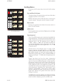
Auxiliary Master Section
MONITOR & FACILITIES SECTION
Auxiliary Master Section
AUX MASTER
Aux Master Panel
The single panel provides output controls for the 8
console-wide busses. Each pair of auxiliary sends can be
configured as two mono sends with independent level
controls, or (by using the numbered ST switches) as one
stereo send with a level (on the odd numbered controls) and
balance (even numbered controls).
After the auxiliary master level controls, the auxiliary outputs
feed a number of destinations:
q To the patch as aux outputs.
q To the aux insert send patch.
BAL
q After the patch insert point, to the meters and
monitor.
8
ON
q After the meters, to the REV SEND outputs and (after
the engineering talkback injection) to the foldback
outputs.
7
ON
5-6
ST
q To the Cue Mix panel.
7-8
BAL
6
q To the reassign panel (aux 1 only, when used as an
LFE mix).
ON
5
ON
BAL
There is a possibility of being able to mix Aux 1 onto Bus 4
(Sub). When this button is selected on the Reassign panel it
will automatically give the aux master level 10dB in hand.
4
ON
3
ON
1-2
ST
3-4
BAL
2
ON
1
ON
+10
sub
Auxiliary Master
Panel
Issue 3
88RS User Manual 5:2
MONITOR & FACILITIES SECTION
Auxiliary Master Section
Split Aux Panel (Optional)
The optional Split Aux panel allows independent aux
outputs for the left and right side of the console, or the
busses can be combined across the console on an
independent basis. The aux split is separate from other split
functions on the console and thus is set and operated
independently of any other split function. Since the Split Aux
panel is physically larger that the standard aux master
panel, it takes the place of 2 Rev Returns, leaving 2 stereo
Rev Returns.
SPLIT
PRE
8
8
PRE
PRE
7
7
PRE
PRE
6
6
PRE
PRE
5
5
PRE
PRE
4
4
PRE
PRE
3
3
PRE
PRE
2
2
PRE
PRE
1
1
PRE
L.H.
R.H.
BAL
BAL
8
8
ON
ON
7
7
ON
ST
ON
7-8
5-6
ST
ON
7-8
5-6
BAL
BAL
6
6
ON
6
5
ON
ON
BAL
BAL
4
4
ON
BAL
4
ON
3
ON
3
3
ON
ON
3-4
1-2
ST
ON
3-4
1-2
BAL
BAL
2
2
ON
ST
3-4
BAL
ON
1
1
ON
ON
ON
+10
sub
L.H. AUX
AUX MASTER
Split Aux Panel
The SPLIT button at the top of the panel enables the function,
and on power up the default position of the button is off,
allowing all 8 auxes from either side of the console to feed
the Master Aux outputs.
Below the SPLIT button there are buttons that together with
the various aux master level controls effectively form an
auxiliary submixer. There are 2 sets of PRE buttons and 2
sets of On/Off buttons. One of each set for both the right
and left side.
2
ON
1
The Split Aux panel has separate master controls for both
the right and left side auxes as well as controls for the global
auxes. The jackfield contains patches for the main aux
outputs, but customer wired varicons are available for Left
Hand and Right Hand outputs.
7-8
ON
5
ON
ST
ST
BAL
ON
5
1-2
8
ON
7
5-6
BAL
R.H. AUX
When the Split mode is not engaged (the default mode), all
8 auxes from both sides of the console will combine globally
and can be accessed from the Master Aux outputs at the
jackfield. In this mode no signal will be present at the Right
Side/Left Side outputs.
When the Split mode is engaged, the On/Off buttons
decide which auxes will also contribute to the Global aux
outputs. If none of these buttons are engaged then all 8
auxes from either side of the console will be completely
separated and their signals can be accessed from the Right
Side/Left Side Aux outputs. No signal will be presented to
the Master Aux outputs.
Any On/Off button engaged will feed it’s associated aux to
both it’s split aux output as well as the Master Aux output.
Any combination can be performed and this allows any
number of auxes to be split or combined across the console
at any time. When an On/Off button is engaged, the “Pre”
buttons decide whether the signal sent to the Master Aux is
pre or post the split aux master level.
The stereo/mono functionality of the Split Aux panel is the
same as that of the standard aux panel.
There is a possibility of being able to mix Aux 1onto Bus 4
(Sub). When this button is selected on the Reassign panel it
will automatically give the aux master level 10dB in hand.
Issue 3
88RS User Manual 5:3
MONITOR & FACILITIES SECTION
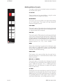
Cue Mix System
Cue Mix System
CUE 1 MIX
7
8
5
6
3
A
U
X
4
A
U
X
1
2
5-6
7-8
1-2
3-4
MON
PATCH
1-2
3-4
5-6
7-8
82
150
FILTER
47
EQ
EQ
There are two alternative cue mix systems – either two stereo
cue mix outputs with high and low frequency shelving, or
four stereo mix outputs with a spectrum tilt control.
Each stereo cue mix is made of the auxiliary, control room
monitor output, main output or patch-field sources selected
on the buttons at the top of the section.
Mixes can be made using the Aux buttons 1, 2, 3 etc. One or
more of these buttons can be used at a time and the source
will be sent to both left and right equally. Stereo cue mixes
can be sourced using the Aux buttons 1-2, 3-4, 5-6, or 7-8,
Mon, Patch, or mix busses 1-8. Odd numbered sources will
feed the left and even feeds the right.
The 88RS channel module, together with the centre section
controls, allow the engineer to set up the pre-fade
auxiliaries to provide intelligent mixes for the artist
independently of the control room monitoring. This includes
sending a mix of multitrack send and return with automatic
level compensation when the track is dropped into record
during an overdub.
The matrix at the top of the module is used to select the
source signals for the cue outputs - this includes a patchbay
socket for a direct input and a facility to select the control
room monitor selector output.
Engineering talkback is injected before the patch bay insert
point.
L
BAL
R
CUE 1 MIX
CUE 2 MIX
7
8
7
5
6
5
3
A
U
X
4
A
U
X
1
2
5-6
8
6
3
A
U
X
1
7-8
4
A
U
X
2
5-6
7-8
1-2
3-4
1-2
3-4
MON
PATCH
MON
PATCH
1-2
3-4
1-2
3-4
5-6
7-8
5-6
7-8
LEVEL
82
150
BAL
82
FILTER
150
47
47
EQ
EQ
FILTER
ON
EQ
EQ
CUE 1
L
BAL
R
L
BAL
R
Cue Mix Panel
LEVEL
LEVEL
BAL
BAL
ON
ON
CUE 1
CUE 2
Dual Cue Mix Panel
Issue 3
88RS User Manual 5:4
MONITOR & FACILITIES SECTION
Cue Mix System
Quad Cue Mix Panel
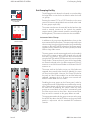
The optional Quad Cue Mix Panel provides 4 stereo or up
to 8 single ear mono mixes.
As with the Dual Cue Mix panel each cue mix can be fed
from the auxiliary, control room monitor output, main
output or 2 patch-field sources selected on the button matrix
within the section.
Each cue section contains 2 level controls with integrated
push on/push off switches. When used as a stereo cue send,
these controls change to 1 level control and 1 balance
control.
Each cue section has 2 stereo patch inputs. Patch 1 is unity
gain and has no level control. Patch 2 has a level control
with 0dB in hand (cut only control).
Each cue section has a simple tilt eq that provides + - 4dB at
1.2k. The eq is applied to both cue feeds of each section
regardless of mode, mono or stereo.
The powerful Quad Cue Mix Panel provides very
comprehensive talkback facilities. Each cue has it’s own
adjustable 0 to -60dB trim preset for the Engineers talkback
as well as a separate overall talkback level control. Use of
the Slate dims all cue mixes by an adjustable level generally
set to -60dB.
Additional controls include a MONO button and a DUAL
button.
In normal operation (neither Mono or Dual engaged),
stereo cue mixes can be sourced using the Aux buttons 1-2,
3-4, 5-6, or 7-8, MON, PATCH 1, PATCH 2 or mix busses
1-2 & 3-4 (or 2trk option). The cue is stereo and it’s controls
include a level control and a balance control. The level
control is 0dB in hand (cut only) and the balance provides
+-6dB either side.
When the MONO button is engaged, odd and even
sources are summed to both left and right and the level and
balance controls remain the same.
When the DUAL button is engaged, all odd numbered
sources are sent to the left ear and all even numbered
sources are sent to the right ear with separate on/off and
level control for each.
Quad Cue Mix Panel
Issue 3
When both the MONO and DUAL buttons are engaged,
aux sends will act the same as in Dual mode while all other
sources are summed to mono and fed to both left and right.
88RS User Manual 5:5
MONITOR & FACILITIES SECTION
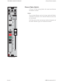
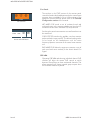
Rev Returns
Rev Returns
These modules provide facilities for up to four stereo
reverberation/effects returns with stereo EQ, filtering, level
and balance/pan control.
The rev returns can be routed to any of the main mix busses
and can also be mixed into the cue sends to the artist’s
headphones.
Rev returns can also be automated by patching one of the
six Encore group master faders (if fitted with the optional
audio boards) in series with the rev return. This gives both an
automated fader and automated mute.
Each rev return stereo input can be sent to the L & R or LS RS
AFL busses for in context AFL soloing.
Reverberation Returns Panel
Issue 3
88RS User Manual 5:6
MONITOR & FACILITIES SECTION
Monitor Panel
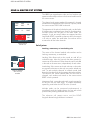
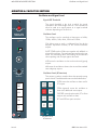
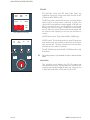
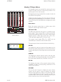
Monitor Panel
The monitor panel provides Master Status, Talkback and
Meter Controls in addition to Control Room and Studio
Loudspeaker control.
STATUS
LOCK
1
2
RTB LEVEL
BROAD
CAST
PHONES
RTB
TALKBACK
MIC
LINE
A
LEVEL
CUT
FADER
SWAP
STUDIO MONITOR
CUES
POST
EQ
FOLLOW
MON
MIX
SEL
CH
EXT
SEL
MON
SEL
MULTITRACK METERS
GRP
ENG
MIXED
CUE
CUES
STATUS
TAPE
In normal monitoring mode there are no VCA's in the signal
path; the volume control is a 24 step switched passive
control. VCA'S only get switched into the monitoring path for
dim and AFL/PFL monitoring.
FOLLOW
MON
EXT
ART
MIXED
CUE
MIX
DOWN
GRP
The standard 88RS monitoring system is comprehensive
and should provide all the surround facilities required for
the majority of users. An optional scoring panel is available
for specialist film scoring applications and formats greater
than 5.1.
SEL/
MON
MONITOR METERS
TAPE
6T MON
GRP
ARM
MONO
STEREO
COMP
ANCILLARY
INSERT
STEM
A
STEM
B
STEM
C
STEM
D
EXT
1
EXT
2
EXT
3
EXT
4
EXT
5
EXT
6
EXT
7
EXT
8
EXT
9
EXT
10
EXT
11
EXT
12
EXTERNAL
AUX
1
AUX
2
AUX
3
AUX
4
MIX
1/2
(2T)
MIX
3/4
MIX
5/6
6T
MIX
AUX
5
AUX
6
AUX
7
AUX
8
CUE
1
CUE
2
CONT
MIX
SUM
SEL MODE
INTERNAL
LARGE
SMALL
AFL
SWAP
AFL
PFL
MINI
INT
EXT
TB
S LS RS
LOCKED ON
CUT
L
CUT
C
CUT
R
CUT
LS
CUT
S
CUT
RS
MIX
MONO
SURR
AFL
L
DIM
ON
BAL
R
ON
LS
SOLO
CUT
DIM
MONO
LEVEL
CONTROL ROOM MONITOR
CHAN
SAFE
MON
SAFE
PFL
LATCH
I/L
RESET
CUT
A
CUT
B
SOLO
LINK
SLATE
REC
SOLO + CUT
GRP
TAPE
O/D
MULTITRACK MONITORS
Issue 3
TB
LEVEL
TB TO
CUES & SLS
RED
LIGHT
TB
OUT
ALL
AUTO
TB
SLS
SLATE
CUE 1
CUE 2
F/B
1-2
F/B
3-4
F/B
5-6
F/B
7-8
REH
TALKBACK
88RS User Manual 5:7
MONITOR & FACILITIES SECTION
Monitor Panel
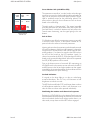
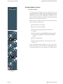
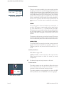
Control Room Speaker Selector
LARGE
SMALL
MINI
CUT
L
CUT
C
CUT
R
CUT
LS
CUT
S
CUT
RS
S LS RS
LOCKED ON
Large, Small and Mini
Loudspeaker Selector
The 88RS has outputs for 3 sets of loudspeakers (Large,
Small and Mini). There are facilities for all 3 sets to be
surround format, sharing the same rear speakers. The large
speakers can be any format up to 5.1 or 7.1 (with the
optional scoring panel) and the small and mini speakers
can be up to LCR or 5.1. Each speaker in each set can be
individually level trimmed.
Selecting the small or mini loudspeakers will normally cut
the surround speakers allowing the small and mini speakers
to be used for stereo or LCR auditioning. Alternatively the
surround speakers can be locked on for use with the small
and mini speakers by pressing the LARGE key twice.
This will toggle the red (S LS RS LOCKED ON) LED below the
large loudspeaker button on and off.
The 3 speaker selector keys are interlocking. When the large
speakers are selected, Return Talkback (RTB) can be
switched to the small and mini speakers with the RTB switch.
Pressing the SMALL key deactivates RTB to Small L and R but
not Mini.
Pressing the MINI key also deactivates RTB to Mini L and R
but not Small.
The trim controls below the small and mini speaker selectors
give +/- 6dB trim relative to the large speakers.
Issue 3
88RS User Manual 5:8
MONITOR & FACILITIES SECTION
Monitor Panel
Control Room Monitor Level Controls
AFL
SWAP
AFL
PFL
INT
These controls set the level of the control room monitor
loudspeakers.
EXT
The main volume control is a ganged, stepped attenuator
that controls the surround sound volume without using
VCA'S. The audio elements of the switch keep each speaker
output to within +/- 0.2dB of each other.
TB
MIX
AFL
DIM
L
BAL
R
Balance Control
ON
ON
The switched balance control has a +/- 3dB adjustment
range (0dB in mid position) and only operates on the L and R
monitor loudspeakers.
DIM Control
The electronically latching dim switch (below the CUT
switches)has an associated variable dim level control with a
range of 0dB to -35dB.
LEVEL
Control Room Monitor
Level Controls
There is an external dim function available on the remote
connector that when operated will dim the monitoring to
the master dim level (0dB to -35dB range) and make the
dim lamp glow half lit.
Operating the engineer’s or producer’s talkback will also
dim the monitor to the preset level and make the dim lamp
glow half lit.
If TB or EXT DIM and Main dim are operated together the
dim attenuations are added.
-
There is also a preset option where the TB controls will operate
the main monitor cut instead of the dim.
These controls are not recallable.
Issue 3
88RS User Manual 5:9
MONITOR & FACILITIES SECTION
Monitor Panel
Monitor Cuts
LARGE
SMALL
MINI
CUT
L
CUT
C
CUT
R
CUT
LS
CUT
S
CUT
RS
CUT L, CUT C, CUT R etc. These keys are used to control
the Monitor Loudspeaker Cuts - whichever speaker set is in
use. The master CUT switch will cut all the speakers together
and can also be operated from a remote control. The
master cut will illuminate the individual speaker cut switches
to half brightness.
S LS RS
LOCKED ON
MONO
SURR
-
LS
SOLO
CUT
DIM
If any individual cuts were already selected then they would
remain cut whether the master cut is operated or not operated.
CUT S (LFE or Sub. Cut) - When 4T is selected as the console
mode this will cut the S loudspeaker and also half light the
lamp irrespective of what other cuts may be applied to that
cut.
MONO
LS SOLO - This switch is used to turn the speaker CUT
switches into speaker SOLO switches.
Monitor Cuts and LS Solo
When LS SOLO is on, pressing any of the LS Cut keys will cut
all the speakers apart from the one pressed.
The action of the Cut keys in LS SOLO mode is momentary,
so releasing the CUT button will cancel the solo.
-
Issue 3
LS Solo function is not available in master cut, EXT, or TB option
cut mode, and if one or more of the cuts were already operated
then pressing the LS Solo button will not change that state, only
pressing another cut would change the rest of the buttons to
solo.
88RS User Manual 5:10
MONITOR & FACILITIES SECTION
Monitor Panel
Monitor Source Selector
Monitor selector switches are not automatable or
recallable.
GRP
TAPE
STEM
A
STEM
B
STEM
C
STEM
D
EXT
1
EXT
2
EXT
3
EXT
4
EXT
5
EXT
6
EXT
7
EXT
8
EXT
9
EXT
10
EXT
11
EXT
12
EXTERNAL
AUX
1
AUX
2
AUX
3
AUX
4
MIX
1/2
(2T)
MIX
3/4
MIX
5/6
6T
MIX
AUX
5
AUX
6
AUX
7
AUX
8
CUE
1
CUE
2
CONT
MIX
SUM
INTERNAL
SEL MODE
INT
EXT
Internal/External Monitor Selectors
The monitoring sources are separated into sources internal
to the console (such as aux outputs and main mix busses)
and sources external to the console (such as replay
machines).
SEL Mode
There are two modes in which the internal and external
selectors interact. These are selected with the SUM switch.
I/L Mode (not SUM)
In this mode the internal selector switches are interlocked
with each other and the external selector switches are
interlocked with each other, so one selection may be made
in each group.
This allows easy comparison of any desk output with any
external source using interlocking INT and EXT keys to
toggle between the pre-selected sources.
When EXT is selected, the selected external source will be
fully lit and the pre-selected internal source switch will be
illuminated at half brightness. However when INT is selected
the pre-selected external source will still be indicated at full
brightness as it may be in use as the source for the studio
loudspeakers or monitor meter.
Mix Mode (SUM)
In this mode only the Aux switches are interlocked with each
other, Cues 1 & 2 are interlocked with each other and 6T
MIX is interlocked with the other MIX buttons. All other
selector switches, including the INT and EXT group masters
are independently latching. This allows virtually any
combination of sources to be mixed together on the control
room monitor outputs.
This mode is useful for “mixed comparision” monitoring
when, for example, it is necessary to hear the music mix on
the console outputs at the same time as a dialogue mix
coming from an external tape machine.
CONT MIX
In this mode it is possible to hear the 6T mix in 3 separate
stored pairs with 1/2 in the front left and right loudspeakers,
3/4 in the centre and sub loudspeakers, and 5/6 in the rear
LS and RS loudspeakers. So you can hear the “in context”
monitoring. In this mode the mix 1/2, 3/4 and 5/6 facilities
will be half lit to show state.
Issue 3
88RS User Manual 5:11
MONITOR & FACILITIES SECTION
Monitor Panel
Internal Monitor Selector
GRP
TAPE
STEM
A
STEM
B
STEM
C
STEM
D
EXT
1
EXT
2
EXT
3
EXT
4
EXT
5
EXT
6
EXT
7
EXT
8
EXT
9
EXT
10
EXT
11
EXT
12
This set of buttons is used to select the internal monitor
source in the following way:
Aux 1 to 8
EXTERNAL
AUX
1
AUX
2
AUX
3
AUX
4
MIX
1/2
(2T)
MIX
3/4
MIX
5/6
6T
MIX
AUX
5
AUX
6
AUX
7
AUX
8
CUE
1
CUE
2
CONT
MIX
SUM
INTERNAL
This set of switches are always interlocked with each other in
mono or stereo irrespective of the sel mode selected. They
select the appropriate Aux O/P signal after the jack insert
point. The auxiliaries can be selected and cancelled as
mono or stereo sources by just pressing one switch (for
mono) or two together (for stereo).
SEL MODE
INT
EXT
Internal/External Monitor Selectors
If Aux 1 is already selected and Aux 1 and 2 are required as
a stereo pair ,then pressing Aux 1 and 2 together will leave
Aux 1 selected and add Aux 2 as the RHS of a stereo pair.
Similarly, if Aux 1 and 2 were already selected, deselecting
just Aux 2 would leave Aux 1 on, which would force the
monitor of Aux 1 out of both L and R speakers.
Mix 1/2, 3/4, 5/6, and 6T Mix
This set of switches selects the main mix outputs after the
output insertion jacks. The operation depends on the SEL
mode selected (CONT MIX or SUM).
When ST (stereo), 7.1, 5.1 or 4T is selected on the reassign
panel, Mix 1/2, 3/4 and 5/6 will behave as regular stereo
sources appearing on the L and R speakers in both the I/L
and SUM modes. Selecting 6T will route busses 1/2 to L and
R, 3/4 to C & S, and 5/6 to LS & RS. If SEL mode is set to
SUM, INT6, other stereo or surround sources will be mixed
onto the front and surround speakers respectively.
If the monitor is selected to CONT MIX then MIX 1/2 will
appear on the L and R speakers, but MIX 3/4 will appear on
the C and S speakers and MIX 5/6 will appear on LS and RS.
6T will be as before, with the 6 busses routed to the 6
speaker outputs. This would be the same effect as selecting
MIX monitor mode and pressing MIX 1/2, MIX 3/ 4 and MIX
5/6 in SUM and CONT MIX format.
-
Regardless of the monitor SEL mode, selecting 6TMix will
always de-select any other mix output selection.
Cue 1 & 2 or Cue 1/2 and Cue 3/4 (for 4 Cue option)
These two switches are also always interlocked with each
other regardless of the monitor SEL mode. They select the
cue outputs after the cue output insertion jacks and can be
mixed with any other source in the SUM monitor SEL mode.
Issue 3
88RS User Manual 5:12
MONITOR & FACILITIES SECTION
Monitor Panel
External Monitor Selector
GRP
TAPE
STEM
A
STEM
B
STEM
C
STEM
D
EXT
1
EXT
2
EXT
3
EXT
4
EXT
5
EXT
6
EXT
7
EXT
8
EXT
9
EXT
10
EXT
11
EXT
12
Of the external sources, stems A-D (GRP and Tape) are
6-wide inputs, EXTS 1-3 are 6-wide and the remaining
sources, EXT4-12, are stereo.
If the console is fitted with the optional Scoring Panel then
the external Stems A-D are 8-wide.
EXTERNAL
AUX
1
AUX
2
AUX
3
AUX
4
MIX
1/2
(2T)
MIX
3/4
MIX
5/6
6T
MIX
AUX
5
AUX
6
AUX
7
AUX
8
CUE
1
CUE
2
CONT
MIX
SUM
INTERNAL
STEM A-D and EXT 1-7 have I/P access from insert points
on the patch. EXT 8 - 12 are customer wired from
connectors in the rear of the monitor section of the console.
SEL MODE
INT
The STEM A-D switches are meant to support external stem
recorders. The interlocked GRP and TAPE switches above
the stem switches allow the operator to select either the
sends to the recorders (GRP) or the playback from the
recorders (TAPE).
EXT
Internal/External Monitor Selectors
-
Issue 3
The Stem A-D Group output sources on the external selector of
the monitoring system are not directly connected to the main
mix outputs as you may expect. These sources are fed from
customer wired multiway varicon connectors which can be
accessed using the Stem A-D output patch points on the
jackfield. This allows maximum flexibility for the record outputs.
88RS User Manual 5:13
MONITOR & FACILITIES SECTION
Master Status
The master status switches in the top left of the master
section control the basic modes and input selection of the
console. They are protected by a STATUS LOCK switch to
prevent inadvertent operation. (This button is not
recallable).
STATUS
LOCK
BROAD
CAST
MIC
Each side of the console can be switched between modes
independently using the arrow switches. The centre keys
switch the whole console. This allows the console to be
configured with a separate monitor section for example.
The console modes are covered in detail in the
Configuration Section of this manual.
Broadcast
LINE
A
FADER
SWAP
MIX
DOWN
STATUS
Master Status Panel
Allows simultaneous broadcast and multitrack recording.
The small fader will control the multitrack mix and the large
fader will control the broadcast signal.
Fader swap is automatically engaged when BROADCAST is
selected, Fader swap can be cancelled whilst broadcast is
still engaged.
Mic and Line A
These switches are used to select the channel inputs across
the console. The selection can be reversed on individual
channels using the input section C/O switch, they are also
automatable.
Fader Swap
The normal power-up state (multitrack recording) is for the
large fader to be in the channel path and the small fader to
be in the monitor path.
The fader swap function reverses this condition across the
console.
Mixdown
In Mixdown mode the channel path comes from the
multitrack return and is directed to the main mix busses via
the routing buttons at the bottom of the channel strip. The
monitor path comes from post the channel fader and is
directed to the multitrack pan and routing keys at the top of
the module (so that the small fader can control additional
effects sends on the multitrack busses).
BROADCAST, MIC, LINE, FADER SWAP and MIXDOWN
are all recallable.
Issue 3
88RS User Manual 5:14
MONITOR & FACILITIES SECTION
Multitrack Monitoring and Overdubbing
GRP
TAPE
O/D
MULTITRACK MONITORS
Multitrack Monitors
The interlocked MULTITRACK MONITORS switches at the
bottom of the Monitor Panel work with the GROUP, TAPE
and O/D switches on individual I/O channels to control the
I/O module monitor path sources across the console.
GRP selects multitrack sends and TAPE selects multitrack
returns.
In overdub and grp arm mode the modules that have the
individual overdub pushbuttons pressed are monitored as
multitrack send. All other modules are monitored as
multitrack return.
For a full description of the overdub operation, please refer
to the Console Configuration Section of this manual.
Issue 3
88RS User Manual 5:15
MONITOR & FACILITIES SECTION
Talkback
A talkback microphone is located at the top of the monitor
panel. There is also provision for an external producer’s
talkback mic (with on/off switch) to be mixed in to the
talkback send. Both talkback mic pre-amps are equipped
with limiters.
1
2
RTB LEVEL
PHONES
The talkback routing is at the bottom of the module and
includes auto talkback to the studio (whenever the tape
machine is stopped or spooling, so the artist doesn’t feel
isolated).
RTB
TALKBACK
RTB Talkback
SLATE
REC
TB
LEVEL
There are three separate talkback level controls for Slate;
Cue and studio loudspeakers; and other destinations (the
patchbay switched and unswitched outputs and the
foldback (aux) outputs.
The TB OUT key in the talkback matrix sends talkback to the
TB Switched Output on the jackfield. The ENG T/B OUTPUT
is unswitched talkback and is continuously present.
TB TO
CUES & SLS
RED
LIGHT
TB
OUT
ALL
AUTO
TB
SLS
SLATE
CUE 1
CUE 2
F/B
1-2
F/B
3-4
F/B
5-6
F/B
7-8
REH
The two RTB controls at the top of the monitor panel control
the Return Talkback level from two inputs on the jackfield.
These inputs are turned on with the latching RTB switch and
are routed to the mini and small loudspeakers.
All the talkback keys are momentary, except the AUTO TB
and TB OUT keys which are latching. Operating any
talkback key dims (or cuts if this option has been
pre-configured) the control room speakers.
TALKBACK
Talkback
-
The AUTO TB key changes CUE 1 and CUE 2 into latching
switches.
Slate
The Slate key routes talkback and a 30Hz tone at a preset
level to the multitrack and main mix outputs. The 30Hz tone
is audible when an analogue tape is dropped against the
tape heads while spooling.
Issue 3
88RS User Manual 5:16
MONITOR & FACILITIES SECTION
Red Light
SLATE
REC
TB
LEVEL
TB TO
CUES & SLS
RED
LIGHT
TB
OUT
ALL
AUTO
TB
SLS
SLATE
CUE 1
CUE 2
F/B
1-2
F/B
3-4
F/B
5-6
F/B
7-8
REH
The RED LIGHT key is used to indicate REHearse or RECord
status. It is a momentary key toggling between REH, REC
and OFF. In record mode SLS TB is inhibited and the SLS
speakers are cut. The SLS TB inhibit and SLS cut do not occur
in Rehearse Mode.
Phones
Located next to the RTB controls this control is for the
headphone socket located in the left leg of the console and
is fed from the Left and Right loudspeaker monitor.
TALKBACK
Talkback
Issue 3
88RS User Manual 5:17
MONITOR & FACILITIES SECTION
Cue Sends
ART
MIXED
CUE
CUES
POST
EQ
ENG
MIXED
CUE
CUES
Cue Controls
The switches in the CUES section of the monitor panel
control the feeds to the headphones and to the control room
monitors when overdubbing. For a full description of the
operation of these switches, please refer to the Console
Configuration section of this manual.
ART MIXED CUE sends a mix of multitrack send and
multitrack return to the monitor prefade cues from the I/O
modules that have their individual O/D keys selected.
6T MON
MONO
INSERT
GRP
ARM
STEREO
COMP
ANCILLARY
Inserts and Lt Rt Return
Switching the control room monitor to cues allows this mix to
be monitored.
CUES POST EQ switches the prefade cues from monitor
paths switched to tape post EQ. This allows backing tracks
to be heard on the headphones with the same
frequency/dynamic correction as the control room monitor
mix.
ENG MIXED CUE allows the engineer to monitor a mix of
track send and return similarly to the Artist's Mixed Cue
Signal.
GRP ARM
Operating GRP ARM and selecting individual channel O/D
switches will allow the master O/D control to switch
between Group/Tape on those nominated channels. This
allows monitoring of chosen console group outputs when
the multitrack machine is parked.
Issue 3
88RS User Manual 5:18
MONITOR & FACILITIES SECTION
PFL/AFL
PFL (Pre-Fade Listen) and AFL (After Fade Listen) are
enabled by setting the central solo mode switches to AFL
(CHAN or MON SAFE) or PFL.
CHAN
SAFE
MON
SAFE
PFL
LATCH
I/L
RESET
CUT
A
CUT
B
SOLO
LINK
The PFL bus is mono and the AFL is stereo, or surround if the
channel LS RS routing button is selected, or LCR if the
channel LCR routing button is also engaged. LS RS AFL can
also be switched to the L and R speakers to check and
balance the surround image. A mixed solo control allows
the LCR AFL to be mixed with the main monitor signal and
the relative levels adjusted, so the solo can be heard in
context.
SOLO + CUT
PFL and AFL (solo safe)
AFL/PFL level control. This pot has a 0dB to -35dB range .
AFL
SWAP
AFL
PFL
INT
AFL/PFL switch. This latching switch is lit when Channel safe
and channel solo are selected or Mon Safe and monitor
solo are selected. This also indicates that solo has been
switched on to the main LS monitors.
EXT
TB
MIX
AFL
DIM
L
BAL
ON
ON
The AFL SWAP switch routes the AFL LS & RS bus to the L and
R speakers.
R
-
This locking switch is only available in Chan or Mon Solo Safe
Mode.
Mixed Solo
LEVEL
This switched control blends the LCR AFL signal and
selected monitor source. The operator hears full AFL at one
end of the travel and full MIX at the other end. It is only active
in Solo Safe mode (AFL or PFL) and not AFL LS RS.
AFL and Mixed Solo
Issue 3
88RS User Manual 5:19
MONITOR & FACILITIES SECTION
Surround Inserts
6T MON
MONO
GRP
ARM
There are two inserts available in the monitor path and also
the ability to monitor the encoded stereo signal (Lt Rt) when
a Dolby Surround matrix is being used. The first insert, which
can be up to 5.1 wide, is after the INT/EXT monitor selector
switch and before the AFL/PFL switching point (ie the soloed
signal will not pass through the inserted matrix). The second
insert is mono and is directly after the monoing amplifier,
which in turn is directly after the surround insert and Lt Rt
monitor return. The mono insert is intended for an Academy
filter.
STEREO
COMP
ANCILLARY
INSERT
Inserts and Lt Rt Return
MONO
The mono signal is the sum of all the active mix busses, ie
just the L & R busses in stereo mode with the other busses
cut, or all the busses in 5.1, 7.1 (if fitted) and 4T mix modes.
The mono mix in stereo mode can be monitored on both the
left and right speakers. If any of the surround modes are
operated the mono’ed signal is routed only to the centre
speaker.
The mono mix has its own pre-inset level control. The mono
insert send can also be used as a mono record output as the
level is unaffected by solos or the main monitor level control
MONO SURR
The MONO SURR trim sets the level that a mono surround
signal is fed to the LS and RS rear speakers. It has a +/10db range and is only active when the console is in 4T
mode.
Ancillary Switches
GRP ARM see page 5:18.
STEREO COMP is used to select the Lt Rt output from the
Dolby Surround matrix to check for stereo (or mono)
compatibility.
-
The Stereo Comp switch only functions in 4T mode.
Studio Monitor
The studio monitor can be switched to follow the same
source selected for the control room monitors or can be
switched to follow the External monitor selector.
LEVEL
CUT
EXT
FOLLOW
MON
The studio speakers are automatically cut when the RED
LIGHT pushbutton in the TALKBACK section is engaged.
STUDIO MONITOR
Studio Monitor controls.
Issue 3
88RS User Manual 5:20
MONITOR & FACILITIES SECTION
2 Track Mixer
2 Track Mixer
The 2T down mixer is a valuable tool for making high quality
simultaneous mixes from the surround outputs of the 88RS
console.
2 TRACK MIXER
- 40
0
- 40
0
- 40
0
- 40
0
ON
ON
ON
ON
1-2
(L-R)
3
(C)
4
(S)
5-6
(LS-RS)
-
POST
INS
+10
2T TO
MON
The source of the feeds to the 2T mixer can be pre fade
(POST INS button not selected) or post fade (POST INS
button selected). This allows for the 2T mix output to have a
"clean feed" none 5.1 output level dependant program or a
mix of what is being recorded to the main 5.1 record
machine.
2T
OUTPUT
2 Track Mixer
There are four level controls with 0dB in hand and ON /
OFF buttons that control the signal feeds to the 2T mixer
from L & R, Centre, Sub and LS-RS console mix outputs.
Contributions from the L & R mix inputs will feed the 2T L & R
outputs respectively.
Feeds from the Centre and Sub will be fed to both L & R of
the 2T mixer outputs.
Contributions from LS-RS mix inputs will be again fed to the
2T L & R outputs respectively.
2T L & R pre fade output jacks are supplied for processing to
be applied across the 2T mix prior to the 2T output level
control.
The 2T output level control will control the final overall level
of the 2T mix. This control has +10dB in hand but can be set
to 0dB in hand if necessary by adjusting the panel mounted
trim pots to the left of the 2T output level control.
-
These trims (left for left 2T output and right for right 2T output)
can also be used to trim the 2T output level if necessary.
If required there is an option to control the 2T output more
accurately, such as when producing the "final" 2T down mix
by substituting the 2T level pot for a stereo fader.
Issue 3
88RS User Manual 5:21
MONITOR & FACILITIES SECTION
Monitoring of the final 2T mix output post the 2T output
jacks is achieved by selecting the 2T TO MON button. This
will flash and send the 2T signal to the 6T monitor where it
will appear instead of mix 1 and 2 on the internal selector,
provided (2T) mix 1 and 2 and internal are selected.
2 TRACK MIXER
- 40
0
- 40
0
- 40
0
- 40
0
ON
ON
ON
ON
1-2
(L-R)
3
(C)
4
(S)
5-6
(LS-RS)
2 Track Mixer
-
POST
INS
+10
2T TO
MON
2T
OUTPUT
-
If this style of monitoring is not favoured then the 2T post fade
output can be cross patched into a spare external input and
monitored that way.
Metering of the final 2T mix output can be simply achieved
by selecting the 2T MTR button on the Aux Meter Panel. This
will cancel any other selection showing on the main meters
and display the L & R 2T output level.
The final output of the 2T mixer can have tone/talkback
injected via tone to mix and slate functions.
Issue 3
88RS User Manual 5:22
MONITOR & FACILITIES SECTION
Monitor and Facilities Fader Section
This section is 16 fader widths wide and is normally fitted
(from left to right) with the following:
1Stereo Main Output Fader
used for left and right mix output.
2 Mono Main Faders
used for centre and mono surround or LFE.
1 Stereo Fader
used for stereo surround.
1 optional Stereo Fader
if Scoring Panel is fitted for LE, RE.
6 Group Faders
These are master faders, normally without audio passing
through them. As an option audio boards may be fitted with
inputs and output on the patch. This allows the level of
external devices, eg rev returns to be automated. A and B
Mute master faders are also an option, see page 4-4.
Automation masters
The Automation Master panel and Events Master panel are
described in the Encore manual.
1 Blank Fader Panel
If the optional LE/RE fader is not fitted.
The remaining area is taken up with the Encore trackerball.
-
Issue 3
Output faders can be mono or stereo for L, R, C, S, LS & RS and
always stereo for LE & RE if fitted. This allows for more or less
groups to be fitted as circumstances dictate.
88RS User Manual 5:23
MONITOR & FACILITIES SECTION
Monitor and Facilities Fader Section
Stereo L & R
Events Master
Mono Centre
Mono Surr or LFE
Automation
Master
Stereo Surr
Group Faders
ALL
SEL
ALL
SEL
ALL
SEL
ALL
ALL
SEL
SEL
ALL
SEL
ALL
SEL
ALL
SEL
ALL
MUTE
MODE
SEL
ALL
MUTE
MODE
SEL
MUTE
MODE
MUTE
MODE
MUTE
A
MUTE
B
LARGE
MUTE
SMALL
MUTE
MIC
LARGE
FADER
SMALL
FADER
LINE
B
AUX 8
MIX+
SHIFT
AUX 7
MIX
MUTE
MUTE
MODE
0
5
MUTE
MUTE
MODE
10
0
5
MUTE
MUTE
MODE
10
0
5
MUTE
MUTE
MODE
10
0
5
MUTE
MUTE
MODE
10
5
MUTE
MUTE
MODE
0
10
10
5
MUTE
MUTE
MODE
0
10
5
MUTE
MUTE
MODE
0
10
5
MUTE
MUTE
MODE
0
10
5
MUTE
MUTE
MODE
0
10
SELECT
OTHER
5
GRP
LINK
COL
TOUCH
AUTO
TOUCH
0
AUX 6
AUX 5
AUX 4
AUX 3
GLIDE
15
GLIDE
15
GLIDE
15
GLIDE
15
GLIDE
5
GLIDE
5
GLIDE
5
GLIDE
5
GLIDE
5
GLIDE
5
REC
20
REC
20
REC
20
REC
20
REC
10
REC
10
REC
10
REC
10
REC
10
REC
10
PLAY
PLAY
30
TRIM
PLAY
30
TRIM
40
ISOLATE
TRIM
40
ISOLATE
50
TRIM
TRIM
TRIM
ISOLATE
50
PLAY
20
30
40
ISOLATE
50
PLAY
20
30
40
ISOLATE
50
PLAY
PLAY
30
TRIM
30
ISOLATE
40
PLAY
20
TRIM
30
ISOLATE
40
PLAY
20
TRIM
30
ISOLATE
40
PLAY
20
TO
END
UNDO
ISOLATE
PLAY
REC
AUX 2
AUX 1
20
INS
TRIM
30
ISOLATE
40
RUN
30
EQ
ISOLATE
40
40
TRIM
ALL/
SCOPE
LF
MUTE
MUTE
MSTR
SF
MUTE
ALL
MODE
LINK
GLIDE
KEEP
RSI/
RESET
AUTOM'N
SELECT
EV ENT S
Monitor & Facilities Fader Section
Issue 3
88RS User Manual 5:24
METERING
Multitrack Meters
METERING
GRP
CH
TAPE MIX
+3
2
+24
20
16
GRP
CH
2
+24
20
16
GRP
CH
TAPE MIX
+3
2
+24
20
16
GRP
CH
TAPE MIX
+3
2
+24
20
16
GRP
CH
TAPE MIX
+3
2
+24
20
16
GRP
CH
TAPE MIX
+3
2
+24
20
16
GRP
CH
TAPE MIX
+3
2
+24
20
16
GRP
CH
TAPE MIX
+3
2
+24
20
16
GRP
CH
TAPE MIX
+3
2
+24
20
16
GRP
CH
TAPE MIX
+3
2
+24
20
16
GRP
CH
TAPE MIX
+3
2
+24
20
16
GRP
CH
TAPE MIX
+3
2
+24
20
16
1
12
1
12
1
12
1
12
1
12
1
12
1
12
1
12
1
12
1
12
1
12
1
12
0
8
0
8
0
8
0
8
0
8
0
8
0
8
0
8
0
8
0
8
0
8
0
8
1
4
1
4
1
4
1
4
1
4
1
4
1
4
1
4
1
4
1
4
1
4
1
4
2
0
2
0
2
0
2
0
2
0
2
0
2
0
2
0
2
0
2
0
2
0
2
0
3
3
4
5
7
10
5
7
10
8
12
3
4
5
7
10
8
12
3
4
5
7
10
8
12
3
4
5
7
10
8
12
3
4
5
7
10
8
12
3
4
5
7
10
8
12
3
4
5
7
10
8
12
3
4
5
7
10
8
12
3
4
5
7
10
8
12
3
4
5
7
10
8
12
3
4
4
5
7
10
8
12
8
12
-20
16
-20
-20
16
-20
-20
16
-20
-20
16
-20
-20
16
-20
-20
16
-20
-20
16
-20
-20
16
-20
-20
16
-20
-20
16
-20
-20
16
-20
-20
16
-20
VU
dBu
VU
dBu
VU
dBu
VU
dBu
VU
dBu
VU
dBu
VU
dBu
VU
dBu
VU
dBu
VU
dBu
VU
dBu
VU
dBu
13
DIR
GRP
50
14
A - MT
TAPE
DIR
GRP
20
50
15
25
12
10
6
SIG
25
0
TAPE MIX
+3
EXP
dB
L/C
15
A - MT
TAPE
DIR
GRP
20
50
15
25
12
10
5
6
0
0
SIG
EXP
dB
L/C
16
A - MT
TAPE
DIR
GRP
20
50
15
25
12
10
5
6
0
0
SIG
EXP
dB
L/C
17
A - MT
TAPE
DIR
GRP
20
50
15
25
12
10
5
6
0
0
SIG
EXP
dB
L/C
18
A - MT
TAPE
DIR
GRP
20
50
15
25
12
10
5
6
0
0
SIG
EXP
dB
L/C
19
A - MT
TAPE
DIR
GRP
20
50
15
25
12
10
5
6
0
0
SIG
EXP
dB
L/C
20
50
15
25
12
10
5
6
0
0
SIG
EXP
dB
21
20
DIR
GRP
A - MT
TAPE
L/C
DIR
GRP
A - MT
TAPE
20
50
15
25
12
10
5
6
0
0
SIG
EXP
dB
L/C
22
DIR
GRP
A - MT
TAPE
20
50
15
25
12
10
5
6
0
0
SIG
EXP
dB
L/C
23
DIR
GRP
A - MT
TAPE
20
50
15
25
12
10
5
6
0
0
SIG
EXP
dB
L/C
24
DIR
GRP
A - MT
TAPE
20
50
15
25
12
10
12
5
6
5
6
0
0
0
0
SIG
EXP
dB
L/C
A - MT
TAPE
20
SIG
15
10
5
EXP
dB
L/C
0
Multitrack Meters
The 88RS meterbridge features high resolution multi-mode
multitrack meters on channels and a comprehensive centre
section for metering mix, monitor and auxiliary outputs.
Multitrack Meters
GRP
TAPE
FOLLOW
MON
Using interlocking centre section switches located on the
monitor panel, the channel meters are switchable between
tape sends (GRP), tape returns (TAPE), Channel input (CH)
or to follow the individual modules’ monitor path input
selection (FOLLOW MON). Indicators in the meter modules
indicate the source selected.
CH
MULTITRACK METERS
Monitor section
Multitrack Meters
When switched to master channel input, the meter point will
normally be after the mic/line selector and before the group
switch. However it is also possible to individually select the
MT meters to channel input via Encore, but if the
direct-input-to-fader facility is used, the meter point will
automatically switch to this input.
-
Both direct to fader and channel input selection can be found in
Encore in the toolbar.
Stem meters (optional)
On the re-assign panel, the MT METER switch will switch the
main mix busses (before the re-assign matrix) on to a preset
section of the multitrack meters either side of the console.
The channel meters will indicate MIX.
Issue 3
88RS User Manual 6:1
METERING
Multitrack Meters
Channel Status
GRP
CH
TAPE MIX
+3
+24
20
16
2
1
12
0
8
1
4
2
0
3
Below the channel meters a hidden till lit display gives key
channel status information – Direct input to fader (DIR I/P),
one of the auxiliaries routed to the multitrack busses
(A®MT) and the monitor input selection (GRP or TAPE).
Dynamics Meter and Signal LED
Two 9-segment LED level indicators show gain reduction for
the limiter/compressor and expander/gate. A SIGnal LED
with adjustable threshold (-30to+26dBu) simultaneously
monitors the channel and monitor path signal levels pre cut
switches, together with the channel signal post the group
switch. This is normally used to indicate potential overload
conditions at key points in the module. The level at which the
LED illuminates is set by a control at the top of the oscillator
panel in the centre section.
4
5
7
10
8
12
-20
16
-20
VU
dBu
1
DIR
GRP
50
A - MT
TAPE
20
SIG
25
15
12
10
6
0
5
EXP
dB
L/C
0
Multitrack
Meter
Issue 3
88RS User Manual 6:2
METERING
Auxiliary Meters
Auxiliary Meters
10
20
40
0
RECALL
SOLO
3 2
7 5
1
80
60
0
1
2
100
3
20
VU
AL19
60
40
20
0
AL19
10
3 2
7 5
40
0
1
80
60
0
1
2
100
VU
PPM
20
40
0
3 2
1
80
60
DIGI
CAL
PEAK
PEAK
HOLD
EXP
CAL
VU
RIDE
60
40
3 2
7 5
0
1
2
100
1
80
60
1
80
0
1
2
3
100
The solo indicator illuminates when a solo switch has been
engaged anywhere on the console.
AUX 6
3
20
VU
AL19
3 2
7 5
10
60
40
0
40
0
Solo and Recall Indicators
VU
1
80
0
1
2
3
100
VU
AUX 4
0
1
2
100
20
AL19
3 2
7 5
10
3
VU
60
40
20
0
AL19
RECALL illuminates when the Recall system is scanning the
console controls During this time the console is muted.
20
AUX 3
10
3
100
AL19
20
20
8 moving coil VU meters show the level of the 8 auxiliary
sends.
2
20
AUX 5
AL19
6dB
DUMP
20
0
7 5
3 2
7 5
10
3
VU
10
1
VU
20
PHASE
80
0
AUX 8
AL19
2T
MTR
1
20
AUX 7
20
3 2
7 5
10
1
80
Phase switch
0
1
2
3
100
20
VU
AUX 1
AUX 2
Switches on the phase meter below the monitor meters in
both 6T and 8T systems.
MON switch
6T Aux Meter Panel
Switches phase meter input from Left Right patch to Left Right
monitor LS outputs.
Operating Level
SOLO
-5
-3
-2 -1
0
+1
VU
+2
+3
-2
-5
-3
-2 -1
0
+1
VU
+2
0
0
+3
-2
6dB
DUMP
DIGI
CAL.
-1
-7
-5
-3
-2 -1
EXP
CAL
VU
RIDE
VU
-1
-7
-5
0
+1
VU
+2
0
+3
-7
-5
-3
-2 -1
0
+1
VU
+3
-2
0
+1
VU
+3
VU
-1
-7
-5
-3
-2 -1
0
+1
VU
+2
0
+3
AUX 4
+2
0
0
-1
-2 -1
+2
AUX 3
VU
-3
0
AUX 6
-2
PEAK
PEAK
HOLD
VU
+3
AUX 5
VU
+1
AUX 8
0
PPM
0
0
-7
-2 -1
-2
VU
-3
+2
AUX 7
-1
VU
-5
0
MON
PHASE
METER
-7
0
-2
R.H.
AUX
MIX
-1
VU
-1
-7
-5
-3
-2 -1
AUX 1
8T Aux Meter Panel
0
+1
VU
+2
0
+3
0
L.H.
AUX
MIX
VU
0
-7
0
0
-1
-2
VU
-2
RECALL
AUX 2
The VU and PPM meters meet international standards for
scales and ballistics. The PPM scale shows the absolute level
in dBu, whereas the VU meter shows the level relative to the
operating level in dB. The operating level is preset to
+4dBu, +6dBu or +8dBu. This also affects the EXP CAL
function described below which enlarges the scale during
tape machine alignment to show signal within + or - 1.2dB
of operating level.
Normal practice with analogue tape is to peak to 0VU
(unseen transients will peak higher) or to 8dB above
operating level with the PPM meters. So the VU meter LEDs
glow brighter (bright up) above 0VU and (normally) the
PPM meters’ bright up point is 1 LED (½ dB) below 8dB over
operating level (eg at +11.5dBu when the operating level is
+4dBu).
Digital tape does not have the same compression
characteristics as analogue tape has as it saturates. Digital
tape just clips over-modulated signals, causing distortion,
so metering peaks is more critical. When recording with
digital tape the average level sent to tape varies according
to the programme type. If the programme material is well
controlled, the level to tape is higher to maximise signal to
noise performance. (Especially with 16bit systems). If the
material is unpredictable, a lower level is used to allow
sufficient headroom for peaks. Usually levels to and from
digital tape machines are greater than those used with
analogue machines.
The 88RS allows for both analogue and digital recording
techniques by providing a 6dB dump facility for the VU scale
and an alternative bright-up point for the PPM scale.
Issue 3
88RS User Manual 6:3
METERING
Multitrack Meter Controls
Multitrack Meter Controls
The mode controls for the multitrack meters are located on
the auxiliary meter panel.
VU & PPM
RECALL
SOLO
These switches set the meter ballistics, using the scales
marked on the left or right of the meters.
BRIGHTNESS
PHASE
The intensity of the meter LEDs can be adjusted by holding
the VU switch down. The meters will step through 4
alternative brightness levels.
6dB DUMP
VU
PPM
6dB
DUMP
DIGI
CAL
PEAK
PEAK
HOLD
EXP
CAL
VU
RIDE
Meter Controls
This switch works in VU mode only and reduces the signal
level to the meters by 6dB (useful when sending higher levels
to digital multitracks for example).
DIGI CAL
This switch works in PPM mode only and changes the bright
up point of the meters to a higher preset level to allow easier
monitoring of potentially clipping signals when working with
a digital multitrack. To set the bright up level, hold down the
PPM switch and use the digi-cal switch to step through
bright-up levels of +14, +16, +18 or +20 dBu.
PEAK
Allows easy monitoring of transients by holding the most
recent peak on a single LED for about a second before
decay (unless superseded by a greater peak). Peak works
with both VU and PPM metering.
PEAK HOLD
This function is the same as Peak, but the peak level is
displayed indefinitely, or until Peak Hold or another mode
button is pressed.
EXP CAL (+4 dB REF)
This switch works in VU mode only. It changes the scale of
the meters for line-up purposes to show signal level plus or
minus 1.2dB of 0 using the –12 to +12 dB region of the
PPM meters with clear indication of whether the signal is
below or above zero.
VU RIDE
Displays the VU level as a solid bar up to the 0 VU mark with
the peak level as a flying dot above the VU level. Using the
6dB dump on the VU scale normally allows the VU display to
fit comfortably below the 0 mark. When used in conjunction
with Peak or Peak Hold, it is the PPM peak that is held.
Issue 3
88RS User Manual 6:4
METERING
Monitor 6T Output Meters
Monitor 6T Output Meters
L1
L
+3
C2
1
C
R3
R
2
S4
S
3
4
LS 5
LS
L
5
Six bargraph meters are provided for metering the main
outputs and other sources as selected by switches in the
monitor panel in the centre section.
RS 6
RS
C
6
R
2
24 +3
20
2
16
24 +3
20
2
16
24 +3
20
2
16
24 +3
20
2
16
24 +3
20
2
16
24
20
16
1
12
1
12
1
12
1
12
1
12
1
12
0
8
0
8
0
8
0
8
0
8
0
8
1
4
1
4
1
4
1
4
1
4
1
4
2
0
2
0
2
0
2
0
2
0
2
0
3
5
7
10
-20
VU
3
4
4
5
7
10
8
12
8
12
16
-20
20
dBu
5
7
10
VU
3
4
8
8
12
16
-20
20
16
20
VU
dBu
8
VU
dBu
dBu
METER SELECTOR OUTPUT
L
180
90
0
-1
0
+1
48v
-15v
+ 16v -
1
2
3
8
Hidden till lit indicators above the meters indicate the format
of the signals being displayed (L, C, R or (bus) 1, 2, 3 etc).
The mix bus format is controlled by the reassign panel mode
switches.
Phase Meter
Below the monitor meters there is a phase meter which
follows the left and right monitor output.
PSU Status LEDs
PSU No
R
+5v
4
5
7
10
12
16
-20
20
VU
3
4
5
7
10
12
16
-20
20
dBu
3
4
5
7
10
12
16
-20
20
VU
dBu
3
8 bargraph meters are provided if the console is fitted with
the optional Scoring Panel.
4
PSU STATUS
The LEDs only illuminate when there is a problem with a
power supply. There are four LEDs to indicate which PSU
has failed and additional LEDs to show which rail has failed:
phantom power (+48V), logic power rails (+5V L & R,
-15V) and audio supply rails (+16V and -16V).
Monitor Meters
The monitor meter modes (PPM, VU, HOLD etc) are
controlled by the multitrack meter mode switches.
The monitor panel meter control switches are interlocking:
MIX
SEL
MON
SEL
EXT
SEL
SEL/
MON
MONITOR METERS
Monitor section meter controls
MIX SEL
This displays the main mix outputs as they appear on the
External Sources Record patch points, ie directly at the main
outputs and before the monitoring selector and associated
inserts.
MON SEL
This displays the monitor selector outputs, after the insert
points, AFL/PFL switching and monoing circuitry and before
the control room monitor level, dim and cut circuitry.
EXT SEL
This displays the output of the external monitor selector,
regardless of what is actually being monitored on the
control room speakers.
SEL/MON
This uses the left 3 meters to display the meter selector
outputs and the right 3 meters to display the monitor
selector outputs (post AFL, as above). The meters show L & R
in stereo mode (meters 2 and 5 unused), or LCR in a
surround mode. This is useful for metering console outputs
and mix machine return levels simultaneously.
Issue 3
88RS User Manual 6:5
METERING
Monitor 8T Output Meters (optional)
Eight bargraph meters are provided for metering the
main outputs and other sources as selected by switches
in the monitor panel in the centre section.
Dot matrix displays above the meters indicate the format
of the signals being displayed (8T1-8, 8TL, 8TR, 8TC
etc.). The mix bus format is controlled by the reassign
panel mode switches and the monitor meter selector.
Phase Meter
Below the monitor meters is a phase meter which follows
the left & right monitor outputs when fitted in a 6T
monitor section and left & right monitor outputs or a
stereo patch input when fitted in an 8T monitor section.
Selection of on/off and source for the phase meter can
be found on the Aux meter panels for both types of
monitor.
8T Monitor Meters
PSU Status LEDs
The LEDs only illuminate when there is a problem with a
power supply. There are four LEDs to indicate which PSU
has failed and additional LEDs to show which rail has failed:
phantom power (+48V), logic power rails (+5V
L & R, -15V) and audio supply rails (+16V and -16V).
2T 1
O/P
2T 2
O/P
STEM
A/E
STEM
B/F
STEM
C/G
STEM
D/H
STEMS
EFGH
SEL/
MON
2T 3
O/P
2T 4
O/P
8T MIX
O/P
MON
SEL O/P
MON
O/P
EXT
DIALOG
FX
MONITOR METER SELECTOR
Monitor section meter controls
The monitor meter modes (PPM, VU, HOLD etc) are
controlled by the multitrack meter mode switches.
The monitor panel meter control switches are interlocking:
2T 1-4 O/P
The interlocked selection of these buttons displays on
meters 7 & 8, the individual 2T outputs as they appear on
the post 2T output insert jacks.
STEM A/E, B/F, C/G, D/H
These display the monitor mix inputs when mapped to stems
as they appear post bus tape switching, but pre trim and mix
level setting.
STEMS EFGH
This control changes the stem A/E, B/F, C/G & D/H select
buttons into 2 distinct banks. When stems EFGH is not
operated then operating A/E, B/F, C/G or D/H STEM will
show stem A, B, C or D on the main meters. However if
stems EFGH is now operated then operating A/E, B/F, C/G
or D/H STEM will show stem E, F, G or H on the main
meters.
Issue 3
88RS User Manual 6:6
METERING
Monitor 8T Output Meters (optional)
SEL/MON
2T 1
O/P
2T 2
O/P
STEM
A/E
STEM
B/F
STEM
C/G
STEM
D/H
STEMS
EFGH
SEL/
MON
2T 3
O/P
2T 4
O/P
8T MIX
O/P
MON
SEL O/P
MON
O/P
EXT
DIALOG
FX
MONITOR METER SELECTOR
Monitor section meter controls
This uses the first 3 meters to display the meter selector
outputs and the second 3 meters to display the monitor
output selector (post AFL, as above). The meters show 1, 2,
3 (LRC) in stereo mode and LCR in surround mode. This is
useful for metering console outputs and mix machine return
levels simultaneously.
8T MIX O/P
This displays the main mix outputs as they appear on the
External Sources Record patch points, ie directly at the main
outputs and before the monitoring selector and associated
inserts.
MON SEL O/P
This displays the monitor selector outputs pre the insert
points, reduction, monoing and AFL/PFL switching circuitry.
MON O/P
This displays the monitor selector outputs after the insert
points, reduction, monoing and AFL/PFL switching circuitry
but before the control room monitor level, dim and cut
circuitry.
EXT
This displays the output of the external monitor selector,
regardless of what is actually being monitored on the
control room speakers.
DIALOG
This displays the 3 wide dialogue inputs as they appear pre
the input level and trim controls.
FX
This displays the 6 wide effect inputs as they appear pre the
input level and trim controls.
Issue 3
88RS User Manual 6:7
METERING
Encore Screen
Encore Screen
The Encore screen is used to display
information about automation and to run
the Recall software. Full details are in the
separate Encore manual.
88RS
Issue 3
88RS User Manual 6:8
SURROUND: ROUTING & MONITORING
Reassign Matrix Panel
SURROUND: ROUTING & MONITORING
The 88RS is designed for ease of use in both stereo and
surround mixing. The standard monitoring system is
designed to handle formats of up to 5.1 wide. Formats up to
7.1 can be monitored using the optional new scoring panel.
Unlike similar large format analogue consoles, 88RS offers
true LCR panning from the channel modules, in addition to
conventional stereo panning.
Reassign Matrix Panel
The reassign matrix controls the main mix format. It
configures the main mix busses for the desired combination
of stereo (LR) and LCR outputs. As standard, the left side of
the reassign matrix governs both sides of the console. Using
Split Mode, each side of the console uses it’s own
independent reassign matrix allowing separate LHS/RHS
surround stems to be printed separately yet monitored
simultaneously.
Reassign Matrix
Issue 3
88RS User Manual 7:1
SURROUND: ROUTING & MONITORING
Reassign Matrix Panel
Main Mix Signal Flow
Both the channel and monitor paths from each input module can route to the four plus one LS RS
(9-10) stereo and one LCR main mix busses. Using the optional DUAL LCR arrow switches on the
re-assign panel, stereo busses 1&2 and 3&4 can be combined to create a second LCR bus on
busses 1-3. (This may be useful if mixing for Dolby EFX cinema format that uses both LCR front and
LCR rear speakers, or just for creating alternate front mixes). The arrow switches allow the busses on
the left and right side of the console to be configured independently.
These mix busses are brought to mix output jacks on the patch via level trims on the re-assign panel
and talk back and tone switching on the monitor anel. They are also fed into the reassign matrix.
The mix busses from the left and right side of the console can be combined into a single (pre
reassign) multi-format console output, or they can be can be split (using the split switch on the
reassign panel), allowing independent left and right side pre-assign console outputs.
The outputs of the reassign matrix are the console’s main mix outputs and these are available on the
patch as EXTERNAL SOURCES RECORD and on the monitoring system as 6T or 8T MIX on the
internal selector.
The 8T/6T reassign mix bus outputs also have patchable direct injects. These are useful for
returning ST or LCR groups into the main mix without using up valuable channel inputs.
-
-
The External Sources Record Outputs on the jackfield are simply parallelled jacks. Connecting to more
than the 6 machines provided for is likely to compromise performance unless adequate buffering is used,
or the optional high power Neve output amps are fitted to the console.
The Stem A-D Group output sources on the external selector of the monitoring system are not directly
connected to the main mix outputs as you may expect. These sources are fed from multiway varicon
connectors on the customer panel which can be accessed using the Stem A-D output patch points on the
jackfield.
When operating in surround formats busses 9-10 should be routed to LS RS surround loudspeakers by
selecting 9-10 to output bus 5 & 6 respectively. This facilitates correct “in position” AFL.
Left hand mix busses
Bus Direct Injects
Reassign
Matrix
Right hand mix busses
Aux 1
Inserts;
Aux 1 to sub;
Master faders;
Talkback and Tone
Main mix o/ps
Right mix, or disabled
Left, or combined mix
Split or Combine
Optional
Manual &
Computer
Control
Main Console Busses, Reassign Matrix, Main Output Busses
Issue 3
88RS User Manual 7:2
SURROUND: ROUTING & MONITORING
Reassign Matrix Panel
Reassign Matrix Panel Controls
The reassign panel operates in stereo mode by default or
surround mode when one of the surround format switches
(7.1, 5.1 or 4-TRK (LCRS)) is engaged.
AUX 1
TO SUB
MT
METER
SPLIT
7.1
5.1
Matrix Switches
In stereo mode, when the console is neither split, nor in
optional dual LCR mode, the LH matrix allows any console
mix bus (except the LCR bus) to be routed to any output mix
bus.
The power-up state of the console is stereo mode with
console busses 1 to 6 (or 8) assigned to output busses 1 to 6
(or 8) respectively.
The pan controls on the channel modules will pan between
the odd (left) and even (right) busses of each pair of busses.
4 - TRK
MODE
Selecting surround modes will affect which console bus to
output bus assignments are allowed.
The matrix always shows the console bus to output bus
assignments.
Reassign Matrix
Panel switches
SPLIT
This switch allows the main mix busses on the left and right
side of the console to be split with independent pre-assign
outputs and independent reassignments from the left and
right to the common set of main output busses.
Split will not split the aux busses left and right, this is now
done via the SPLIT button on the Split Aux panel.
LCR ¬ and ® (optional)
These switches will only function if the option is fitted and
one of the surround modes is selected.
These switches convert busses 1, 3 and 2 to a second LCR
bus. The LH arrow switch controls both sides of the console
unless SPLIT is selected on the dual re-assign panel, when
the arrow switches will affect the LHS and RHS of the console
independently. Bus 4 is muted.
When the console busses 1, 3 and 2 are used as an LCR
bus, these console busses may only be assigned to their
equivalent numbered output bus (1 to1, 3 to 3 and 2 to2)
which are the console’s LCR outputs. Bus 4 cannot be
assigned to any output and the remaining console busses
can be freely assigned to any output bus within the currently
selected surround format (4 TRK, 5.1 or 7.1). (See drawings
at the end of this section)
Issue 3
88RS User Manual 7:3
SURROUND: ROUTING & MONITORING
Reassign Matrix Panel
Aux 1 to Sub
AUX 1
TO SUB
MT
METER
SPLIT
7.1
The AUX 1 TO SUB facility allows auxiliary 1 to be used to
create the LFE (Low Frequency Extension, or sub-woofer)
mix. The post aux 1 level output is re-introduced to the
console via a normalled jack point before the master fader
in a 5.1, 6.1 or 7.1 mix. This allows control of the LFE mix
independently of the surround mix. There is also an insert
provision on the LFE main mix output for an external filter, or
low frequency synthesizer.
The standard 88RS Series main output is six signals wide,
suitable for formats up to 5.1 (inc. LFE on aux 1). Fitting the
optional scoring panel expands this to 8 main outputs, for
7.1 format mixing and the addition of an internal LFE filter
on bus output 4.
5.1
This switch has no function in 4 TRK mode (LCRS).
4 - TRK
MODE
MT Meter (optional)
This control switches a pre-set section of the multitrack
meters to meter the left and right pre-assign mix bus outputs.
The meters are indicated with the legend “MIX”.
MODE Switches
Reassign Matrix
Panel switches
These buttons set the overall mode of the console for stereo
(when no switches are on), 7.1 (requires scoring panel
option), 5.1 or 4-TRK (LCRS). 6.1 format mixing is
supported by selecting 5.1, with dual LCR (optional) and
AUX 1 TO SUB also selected.
These switches affect the reassign matrix, monitoring and
meter routing in ways that are described in each of these
sections of this manual.
Mix output trims
The reassign panel has trim controls for the left and right pre
matrix mix bus outputs, the main mix outputs are controlled
by the master faders.
These trims can also be factory set to be post re-assign
matrix.
Issue 3
88RS User Manual 7:4
SURROUND: ROUTING & MONITORING
Reassign Matrix Modes
Reassign Matrix Modes
MASTER MIX BUS INPUTS LHS
1(L) 2(R) 3(C)
4
ON
ON
ON
ON
5
6
7
8
9
10
ON
ON
ON
ON
ON
ON
MIX BUS INPUTS RHS
1(L) 2(R) 3(C)
LCR
4
5
6
7
8
MASTER MIX BUS INPUTS LHS
9
10
LCR
1(L) 2(R) 3(C)
4
5
6
7
8
9
10
MIX BUS INPUTS RHS
LCR
BUS 1
BUS 1
BUS 2
BUS 2
BUS 3
BUS 3
BUS 4
BUS 4
BUS 5
BUS 5
BUS 6
BUS 6
ON
ON
ON
ON
ON
ON
ON
ON
ON
ON
ON
ON
ON
ON
ON
ON
ON
ON
ON
ON
ON
ON
ON
1(L) 2(R) 3(C)
4
ON
ON
ON
ON
5
6
7
8
ON
ON
ON
ON
ON
RH BUS CUT
LH BUS CUT
RH BUS CUT
MASTER MIX BUS INPUTS LHS
MIX BUS INPUTS RHS
MASTER MIX BUS INPUTS LHS
MIX BUS INPUTS RHS
MASTER MIX BUS INPUTS LHS
1(L) 2(R) 3(C)
4
5
6
7
8
9
10
1(L) 2(R) 3(C)
LCR
ON
Stereo + Split Mode
MIX BUS INPUTS RHS
LCR
10
ON
LH BUS CUT
Power-up Mode
9
4
5
6
7
8
9
10
LCR
BUS 1
BUS 2
BUS 3
Additional output busses 7/8 are available when
an 8T panel is fitted on SP consoles. In this
configuration Power-up Mode routes input 7 to
output 7 and input 8 to output 8.
BUS 4
Stereo Mode makes input busses 1-10 selectable
to output busses 7 & 8 on the LH side matrix only.
BUS 5
BUS 6
ON
ON
ON
ON
ON
ON
ON
ON
ON
ON
ON
ON
ON
ON
ON
ON
ON
ON
ON
ON
ON
LH BUS CUT
RH BUS CUT
MASTER MIX BUS INPUTS LHS
MIX BUS INPUTS RHS
Stereo + Split Mode makes input busses 1-10
selectable to output busses 7 & 8 on both sides of
the matrix.
ON
Stereo Mode
Issue 3
88RS User Manual 7:5
SURROUND: ROUTING & MONITORING
MASTER MIX BUS INPUTS LHS
1(L) 2(R) 3(C)
4
ON
ON
ON
ON
5
6
7
8
9
10
ON
ON
ON
ON
ON
ON
Reassign Matrix Modes
MIX BUS INPUTS RHS
1(L) 2(R) 3(C)
LCR
4
5
6
7
8
MASTER MIX BUS INPUTS LHS
9
10
LCR
1(L) 2(R) 3(C)
4
5
6
7
8
9
10
MIX BUS INPUTS RHS
LCR
BUS 1
BUS 1
BUS 2
BUS 2
BUS 3
BUS 3
BUS 4
BUS 4
BUS 5
BUS 5
BUS 6
BUS 6
ON
ON
ON
ON
ON
ON
ON
ON
ON
ON
ON
ON
ON
ON
ON
ON
ON
ON
ON
ON
ON
ON
ON
1(L) 2(R) 3(C)
4
ON
ON
ON
ON
5
6
7
8
ON
ON
ON
ON
ON
RH BUS CUT
LH BUS CUT
RH BUS CUT
MASTER MIX BUS INPUTS LHS
MIX BUS INPUTS RHS
MASTER MIX BUS INPUTS LHS
MIX BUS INPUTS RHS
MASTER MIX BUS INPUTS LHS
1(L) 2(R) 3(C)
4
5
6
7
8
9
10
ON
ON
ON
ON
ON
ON
ON
ON
ON
ON
ON
LCR
ON
5.1 + (optional) Dual LCR Mode
MIX BUS INPUTS RHS
1(L) 2(R) 3(C)
LCR
10
ON
LH BUS CUT
5.1 Mode
9
4
5
6
7
8
MASTER MIX BUS INPUTS LHS
9
10
LCR
1(L) 2(R) 3(C)
4
5
6
7
8
9
10
MIX BUS INPUTS RHS
LCR
BUS 1
BUS 1
BUS 2
BUS 2
BUS 3
BUS 3
BUS 4
BUS 4
BUS 5
BUS 5
BUS 6
BUS 6
ON
ON
ON
ON
ON
ON
ON
ON
ON
ON
ON
ON
ON
ON
ON
ON
ON
ON
ON
ON
ON
ON
1(L) 2(R) 3(C)
4
ON
ON
ON
ON
ON
ON
ON
ON
ON
ON
5
6
7
8
LH BUS CUT
RH BUS CUT
LH BUS CUT
RH BUS CUT
MASTER MIX BUS INPUTS LHS
MIX BUS INPUTS RHS
MASTER MIX BUS INPUTS LHS
MIX BUS INPUTS RHS
9
10
LCR
ON
5.1 + Split Mode
5.1 + (optional) Dual LCR + Split Mode
Additional output busses 7/8 are available when
an 8T panel is fitted on SP consoles. In this
configuration 5.1 Mode makes input busses 1-10
selectable to output busses 7 & 8 on the LH side
matrix only.
5.1 + (optional) Dual LCR Mode makes input
busses 5-10 selectable to output busses 7 & 8 on
the LH side matrix only.
5.1 + Split Mode makes input busses 1-10
selectable to output busses 7 & 8 on both sides of
the matrix.
Issue 3
5.1 + (optional) Dual LCR + Split Mode makes
input busses 5-10 selectable to output busses 7 & 8
on both sides of the matrix.
88RS User Manual 7:6
SURROUND: ROUTING & MONITORING
MASTER MIX BUS INPUTS LHS
1(L) 2(R) 3(C)
4
ON
ON
ON
ON
5
6
7
8
9
10
ON
ON
ON
ON
ON
ON
Reassign Matrix Modes
MIX BUS INPUTS RHS
1(L) 2(R) 3(C)
LCR
4
5
6
7
8
MASTER MIX BUS INPUTS LHS
9
10
LCR
1(L) 2(R) 3(C)
4
5
6
7
8
9
10
MIX BUS INPUTS RHS
LCR
BUS 1
BUS 1
BUS 2
BUS 2
BUS 3
BUS 3
BUS 4
BUS 4
BUS 5
BUS 5
BUS 6
BUS 6
ON
ON
ON
ON
ON
ON
ON
ON
ON
ON
ON
ON
ON
ON
ON
ON
ON
ON
ON
ON
ON
ON
ON
1(L) 2(R) 3(C)
4
ON
ON
ON
ON
5
6
7
8
ON
ON
ON
ON
ON
RH BUS CUT
LH BUS CUT
RH BUS CUT
MASTER MIX BUS INPUTS LHS
MIX BUS INPUTS RHS
MASTER MIX BUS INPUTS LHS
MIX BUS INPUTS RHS
MASTER MIX BUS INPUTS LHS
1(L) 2(R) 3(C)
4
5
6
7
8
9
10
ON
ON
ON
ON
ON
ON
ON
ON
ON
ON
1(L) 2(R) 3(C)
ON
LCR
ON
4-TRK + (optional) Dual LCR mode
MIX BUS INPUTS RHS
LCR
10
ON
LH BUS CUT
4-TRK mode
9
4
5
6
7
8
MASTER MIX BUS INPUTS LHS
9
10
LCR
1(L) 2(R) 3(C)
4
5
6
7
8
9
10
MIX BUS INPUTS RHS
LCR
BUS 1
BUS 1
BUS 2
BUS 2
BUS 3
BUS 3
BUS 4
BUS 4
BUS 5
BUS 5
BUS 6
BUS 6
ON
ON
ON
ON
ON
ON
ON
ON
ON
ON
ON
ON
ON
ON
ON
ON
ON
ON
ON
ON
ON
ON
1(L) 2(R) 3(C)
4
ON
ON
ON
ON
ON
ON
ON
ON
ON
ON
5
6
7
8
LH BUS CUT
RH BUS CUT
LH BUS CUT
RH BUS CUT
MASTER MIX BUS INPUTS LHS
MIX BUS INPUTS RHS
MASTER MIX BUS INPUTS LHS
MIX BUS INPUTS RHS
4-TRK + Split mode
9
10
LCR
ON
4-TRK + (optional) Dual LCR + Split mode
Additional output busses 7 & 8 are available when
an 8T panel is fitted on SP consoles. In this
configuration inputs 1-10 are not selectable to
output busses 7 & 8 on either side of the matrix
in any 4-TR Mode.
Issue 3
88RS User Manual 7:7
SURROUND: ROUTING & MONITORING
Automated Panning
Automated Panning
Linear panning (from any channel to any two busses) may be
automated by using the small fader in conjunction with the
large fader to create interlinked sends to two busses. Special
software controls the relationship between the two faders to
ensure a correct pan law. This is a standard feature of the
88RS, but there is also an option to fit two fully automated
joysticks to provide free panning between the busses of any
surround format.
Fader Panning
TRACK
Assignable
Button
DIR
To use the large and small faders for automated panning
ä Send the same source to both the large and small fader
GRP
TAPE
in the channel module.
O/D
TO MTK
ALL
SEL
C/O M
SWAP
10
O
D
E
MUTE
MODE
SMALL
FADER
CH.0P
CH. I P
5
SF
MUTE
DYN
0
INS M
O
N
5
EQU I
10
T
O
LF
MUTE
P
A
T
H
MUTE
MODE
FILT R
20
7-8
P+G
30
5-6
A
U
X
P+G
40
3-4
ä To continue the example route both faders to MIX 1-2
5
and set the large fader pan hard left and the small fader
pan hard right so that the large fader is routed to bus 1
only and the small fader is routed to bus 2.
0
MODE
5
CUT
REC
10
SEL
ä Press LINK on the Automation master panel.
PLAY
20
ä Press the assignable button (top right) on the chosen
1-2
3-4
5-6
7-8
9-10
LS/RS
SF
TRIM
30
ISOLATE
LCR
40
NAR
ST
C
PAN
L
R
A
group fader (which will then flash green). If the group
fader was previously in an automation mode, it will go
into isolate.
ä On the channel fader (or faders), press the assignable
B
CUT
SOLO
Then set up a group fader to be the pan control (ie, create a
pan link).
GLIDE
RET
R
E
C
ä Route the faders to the two mix busses.
10
1-2
SOLO
For example, if in mixdown mode with the tape return
feeding the large fader press TAPE so that the return also
feeds the small fader or use the CH.IP mode on the CH.OP
CH.IP button.
button which will illuminate green.
The small and large faders are then pan-linked and under
control of the group fader. As the group fader is moved up
or down, the small fader will follow, but the large fader will
move in the opposite direction creating a pan effect.
Small and Large Faders
The centre position of the group fader pan is the -10
position. When the group fader is set to centre, both the
large and small faders on the channel will be set to -3dB (or
-4.5dB if so set in the miscellaneous preferences of Encore).
Issue 3
88RS User Manual 7:8
SURROUND: ROUTING & MONITORING
Optional Joystick Module
When the group fader is moved to either the top or the
bottom of its travel, one of the channel module faders will be
at the 0dB position and the other will be attenuated,
normally to -60dB (corresponding to a narrow divergence).
This can also be set to -40 or -50 dB in the miscellaneous
preferences for a wider divergence.
-
The preferences only over-ride the default values when the
Encore program has been started.
Moving the large channel fader up or down will also move
the small fader by the same amount (in the same direction),
making the large fader the overall level control. The pan
relationship is preserved.
Automation for both small and large fader is controlled
from the large fader whenever pan link is on. (Not from the
group fader, so no automation coalescence is required).
The group fader will however replay any automated pan
moves while the pan link is on.
The pan link can be terminated by deselecting either of the
assignable buttons, or the master link.
-
For surround panning, it may be easier to route and pan the
faders to MIX 7-8 and reassign these busses to whichever
monitor busses are required using the reassign matrix.
Optional Joystick Module
SCR
The two optional joysticks are able to pan any channel
across the mix-busses in a stereo, LCR, 5.1, 6.1 or 7.1
format. It does this by remotely controlling a set of small
faders (the pan set) that control the level sent to each bus in
the chosen format. Each small fader controls the individual
left, centre, right, left-surround, right surround, left-extra,
right-extra or sub-woofer contribution to the mix. This
approach couples the flexibility and power of the automated
joysticks with the sonic purity of passive gain elements of
faders in the signal path.
SCR
TOUCH
JUMP
TOUCH
MODE
DIV
MODE
DIV
GLIDE
LCR
GLIDE
LCR
REC
FB
REC
FB
PLAY
LR
PLAY
LR
ISOLATE
CALL
ISOLATE
CALL
Automated Joysticks
JUMP
The system allows multiple pan sets, so that it is possible to
pan one channel across all elements of a 5.1 mix for
example and at the same time pan another channel across
just the front left and right speakers of the mix with a
phantom centre.
There are three steps to using the joysticks:
q Configure a group of small faders to use as a pan set.
q Set up the console routing.
q Call the pan set onto the joysticks and start panning.
Issue 3
88RS User Manual 7:9
SURROUND: ROUTING & MONITORING
Optional Joystick Module
Configuring Pan Sets
This can be done before or after the console routing is set.
ä Press the SCR button on either of the joystick modules to
open the Configuration screen.
ä Using the trackball, click on the required surround
format designation box on the left of the screen.
It will go white to indicate that it has been selected.
Decide whether a hard or phantom centre is required, or
whether or not a fader is needed for the sub-woofer and
check the appropriate box below the format selectors.
Configuration Screen
-
The joystick does not control the sub-woofer contribution. It is
included in the pan set only for the convenience of having the
sub-woofer contribution fader in the same area as the
associated pan set.
ä Move the mouse pointer over the track display on the
right of the screen.
Note that a group of tracks will go white indicating where
the pan set is going to be positioned on the console.
ä When the correct set of tracks are highlighted, left click to
confirm the selection.
The tracks will change colour according to the format: blue
for stereo; orange for LCR; green for 5.1; violet for 6.1 and
red for 7.1 and the pan designator (L, C, R etc) will be shown
in the box next to the track number. The display will show L,
C and R for LCR panning with a hard centre or LP and RP for
panning with a phantom centre.
ä To move a pan set, left click on it and it will turn back to
white and be movable.
ä To delete a pan set, left click to turn it white, then right
click to delete.
“Pan Set” Display
As the small fader mapping progresses the “PAN SET” list
will be displayed on the screen showing the relationship
between each pan set and the tracks it uses. The pan sets
can be given distinguishing names by double-clicking on
the default name in the list and over-typing it.
Configure the console routing
The small faders in the pan set need to be fed to the signal to
be panned and to be routed to the appropriate mix busses.
This can be done as follows:
ä Route the channel (or channels) that is to be panned with
the joysticks to the multitrack busses that make up the
pan set.
Issue 3
88RS User Manual 7:10
SURROUND: ROUTING & MONITORING
Optional Joystick Module
For example, if the console is in mixdown and channel 20 is
to be panned in 5.1 format using a pan set on small faders
1-6, press C/O on channel 20 so that the large fader routes
to the multitrack busses and press multitrack routing buttons
1-6.
On channels 1-6, press the Group buttons, so that the small
faders pick up the busses fed by channel 20. Route the small
faders to the surround busses, eg route channel 1 small
fader to MIX LCR and pan left; route small fader 2 to MIX
LCR and pan centre etc.
At this point it is useful to check the routing by playing audio
through channel 20 and confirming that it appears in the
appropriate speakers when the individual faders 1-6 are
opened one at a time.
Using the optional joysticks
The joystick module has a matrix display that shows the real
position of the panned audio with a diamond shape and the
position of the joystick with a single dot. Around the matrix,
speaker symbols illuminate to show the format of the pan set
being controlled. Below the matrix, two alphas show the
name of the panset and the divergence (spread) of the pan.
SCR
SCR
TOUCH
JUMP
TOUCH
MODE
DIV
MODE
DIV
GLIDE
LCR
GLIDE
LCR
REC
FB
REC
FB
PLAY
LR
PLAY
LR
ISOLATE
CALL
ISOLATE
CALL
Joystick module
JUMP
To select which pan set each joystick controls, use the
inverted triangle switch to scroll through the list of available
pan sets.
There are then 3 ways of taking control of the selected pan
set. Whichever method is used, the faders will initially jump
to a valid setting for the joystick control (if not already in a
valid position). They will then move in response to joystick
movements.
The TOUCH method
ä Press TOUCH.
Moving the joystick will not affect the audio until it has been
moved close to the same position that the audio is already
in, i.e. the dot touches the diamond. The joystick will pick up
the audio and move it with the joystick moves. This mode is
useful for updating an existing mix. It prevents the audio
jumping suddenly when the joysticks are activated.
The CALL method
ä Press CALL.
Moving the joystick will cause the audio to pan immediately,
but the audio pan position will remain offset from the
joystick position. If the offset is large when CALL is pressed,
this will restrict the field through which the audio can be
panned. The idea is to move the joystick close to the audio
position before pressing CALL.
Issue 3
88RS User Manual 7:11
SURROUND: ROUTING & MONITORING
Optional Joystick Module
This method makes it possible to drop the joystick into
recording automation immediately the CALL button is
pressed, without having the audio jump to the joystick
position.
The JUMP method
ä Press JUMP.
The audio will immediately jump to the position of the
joystick. The automation mode takes effect as soon as JUMP
is pressed.
JUMP can also be used when the joystick is in Call or Touch
mode to bring the audio to the joystick position.
Divergence, which is the apparent spread of the panned
source in the sound field, is set using the scroll keys to either
side of the lower alphanumeric. Divergence changes can be
automated using the MODE switch in conjunction with the
automation switches below.
The overall level going to the mix is controlled using the
fader in the channel that is routed to the pan set faders.
Issue 3
88RS User Manual 7:12
AUTOMATION & MACHINE CONTROL
Global Master Automation
AUTOMATION & MACHINE CONTROL
88RS has automation, recall and machine control included
as part of the Encore package as standard. These topics are
covered in the Encore For 88RS User manual.
LARGE
MUTE
SMALL
MUTE
LARGE
FADER
SMALL
FADER
Global Master Automation
The Global Master Automation module located in the
monitor fader area controls the automation modes for the
faders and mutes across the console.
MIX+
SHIFT
MIX
SELECT
OTHER
GRP
LINK
COL
TOUCH
AUTO
TOUCH
RUN
TO
END
UNDO
ISOLATE
PLAY
REC
TRIM
GLIDE
ALL/
SCOPE
KEEP
AUTOM'N
Global Master
Automation Module
Issue 3
88RS User Manual 8:1
AUTOMATION & MACHINE CONTROL
Events Master
Events Master
The events master is used to control the automation of
channel module switches (events). This module is used in
conjunction with the Automation Global Master module to
set independently for the left and right side of the console.
MIC
LINE
B
AUX 8
AUX 7
AUX 6
AUX 5
AUX 4
AUX 3
AUX 2
AUX 1
INS
EQ
LF
MUTE
ALL
RSI/
RESET
MUTE
MSTR
SF
MUTE
MODE LINK
SELECT
EV ENT S
Global Events
Issue 3
88RS User Manual 8:2
AUTOMATION & MACHINE CONTROL
Automation Panel
Automation Panel
The keyboard for Encore is built into the control surface and
includes shortcut keys.
ROUTE DYN
AUX
EQ
FDR
ALL
S1
S2
S3
S4
S5
S6
S7
S8
!
1
@
2
#
3
$
4
%
5
^
6
&
7
*
8
_
-
+
=
{
[
}
]
:
;
"
'
?
/
S9 S10
(
9
|
\
Q W E R T Y U
I
)
0
BACK
O P
The MCS panel provides machine control for up to 8 groups
of transports. Each group may be a single machine, or
several depending on whether an external synchroniser
system is used. The transport keys control the currently
selected group.
A S D F G H J K L
Z X C V B N M <, >.
CAPS
LOCK
SHIIFT
ALT
CTL
RETURN
7 8 9
TIME
INSERT HOME PAGE ESCAPE
UP
4
5 6
FROM
DELETE END
1
-
2 3
TO
NUM
LOCK
SHIFT PRINT UNDO CANCEL
.
0 +
ALT
E
X
E
C
U
T
E
TAB
NEW LOAD
SNAP SNAP
LABEL MUTE FADER EVENT
MIX
FILING MERGE CODE
TREE
MCS
SAVE LOAD
COPY
ALL
TO END
RECALL
REH
PAGE
HELP
DOWN
EDIT CYCLE
IN
OUT
MASTR
SOLO
OFFST
ENTRY
STAT
HR
STORE
F1
BARS MIN
F2
F3
RECALL
FEET SEC BEATS FRAME
LOCK
JOG
CLEAR
GRAB
TIME
E
N
T
E
R
LOC
ROLL
BACK
REV
GROUP
ONLINE
OFFSET
BUSY
LOCK
REC
MACH
AUX
M/C
OFFSET
REW
1
1
1
1
1
1
1
1
2
2
2
2
2
2
2
2
3
3
3
3
3
3
3
3
4
4
4
4
4
4
4
4
M/C
GROUP
FFWD
5
5
5
5
5
5
5
5
6
6
6
6
6
6
6
6
7
7
7
7
7
7
7
7
TRIM
8
8
8
8
8
8
8
8
M/C
SOLO
PLAY
STOP
REC
Automation Panel
Issue 3
88RS User Manual 8:3
GLOSSARY
Terms Used In This Manual
GLOSSARY
Terms Used In This Manual
AFL (After Fade Listen)
Allows users to monitor individual channels after the fader, without affecting the main outputs. An
AFL bus sums all the AFL’d signals and is routed to monitoring. AFL on 88RS is a surround bus to
allow monitoring of individual channels in their panned positions.
Attenuation
The reduction in level of a signal.
Audio grouping
Channels in an audio group are mixed together to form a single output under control of a single
fader. This differs from VCA grouping, where channels under control of a single fader still have
discrete outputs. Tape sends (sometimes referred to as group outputs) are an example of audio
groups.
Channel Outputs
routed to a Group
Group Master
Group Fader
From channel
group routing
Summing
Amplifier
See also CONTROL GROUPING.
Aux
Auxiliary outputs from the console are secondary mix-busses used for foldback and effects sends.
Each channel has independent sends with level control to a number of aux busses, which have
overall output controls located in the centre of the console. Auxes can be mono or stereo. Effects
returns are brought into spare input channels or dedicated Rev returns (also known as echo or aux
returns) in the centre of the console.
Bell
Used to describe a ‘peaking’ equaliser rather than a shelving one.
Bounce
Allows the monitor signal of a particular channel to be routed back to the track assignment busses
for ‘bouncing down’, where a number of previously recorded signals are re-recorded onto different
tracks usually with some mixing. Achieved on 88RS by using the small fader C/O switch and large
fader cut or (optionally) pulling the group output pot to its up position.
Issue 3
88RS User Manual 9:1
GLOSSARY
Terms Used In This Manual
Bus
A ‘Summing point’ for all signals routed to the same place.
A bus will usually be either a balanced or unbalanced line running most of the length of the console
carrying a signal for a particular destination (e.g. ‘stereo mix bus’ picks up all signals routed from
channels to the stereo mix).
Channel
Traditionally a term used for an input path on the mixing console, occasionally used for output
channels as well. Also used as a name for the input module as a whole.
In this manual the term is generally used to describe the path from microphone to multitrack tape
(where ‘monitor’ designates the return from multitrack to mix on an in-line console).
Clipping
Clipping occurs when the electrical level of an audio signal exceeds the maximum permitted level,
resulting in squaring-off of the waveform and distortion.
Comms
Abbreviation of ‘communications’ (the talkback between artists and control room).
Control grouping
The levels of faders in a group are controlled from one fader (each maintaining its level in relation to
the others), but their outputs remain separate - (i.e. unlike audio grouping it does not involve a
single summed audio output for the group). Sometimes called VCA grouping.
Control room monitor
Used to adjust the level and other attributes of the control room loudspeakers independent of the
mix output.
Cue
An output from the console which carries a mix of signals to artists for monitoring on headphones.
The 88RS has a flexible cue system allowing the engineer to send artists the appropriate headphone
feed at all times.
Cut
A switch to mute the relevant signal from its destination (e.g. the CUT switch on the channel fader
cuts that channel from the mix).
Also known as mute.
Echo Returns
Also known as Rev returns or Aux returns, this are dedicated inputs in the centre section of the
console.
Effects send
Another name for aux send.
Issue 3
88RS User Manual 9:2
GLOSSARY
Terms Used In This Manual
EQ
Abbreviation for EQUALISATION (a means of controlling the frequency characteristics of a signal ).
Equalisers are a collection of individual filters, usually 4 (4-band EQ).
Fader
A sliding gain control with full attenuation at the bottom of its travel, and in the case of channel and
monitor faders, +10dB gain at the top. Output faders have 0dB gain at the top.
Filters
Separate from the EQ filters there are additional high and low pass filters for controlling noise at the
input to the channel.
Foldback
Outputs from the console to artists headphones (eg CUES).
Gain
The amount of amplification provided by any stage in the signal chain (negative gain is
ATTENUATION).
HPF (high pass filter)
Allows the passage of signal content which is above the filter frequency.
Input module
A physical module which carries an input from an external source and routes it to other destinations
on the console.
Jackfield
A collection of sockets carrying signals to and from various points in the console signal chain and
external equipment to allow ‘patching’ of signals from location to location.
Limiter
Used to limit the maximum level of a signal.
This can either be for effect, or to prevent overload elsewhere in the system.
Link
Allows users to couple the dynamics control signal between adjacent channel modules, eg for the
dynamics to operate simultaneously on stereo pairs or surround inputs with no image shift
occurring.
LPF (low pass filter)
Allows the passage of signal content which is below the filter frequency.
Module
A piece of removable hardware in the control surface of the console (e.g. ‘master module’ or ‘input
module’).
Issue 3
88RS User Manual 9:3
GLOSSARY
Terms Used In This Manual
Normalling
The way in which an output jack (socket) is wired to an input jack so that the source is routed to its
“normal” destination when no (patch cable) plugs are in the sockets. A “half normalled” connection
allows a listen jack to be inserted without breaking the “normalled” connection - these are normally
used in insert and other line level signals. A fully normalled connection is broken when a plug is
inserted in either the source or destination socket - these are used on mic level signals.
Null LEDs
Automated faders are provided with null LEDs which point in the direction that the fader must be
moved to make its position correspond to the gain of the automation pass.
Oscillator
Produces tones at various frequencies for lining up the system.
It can be routed to a number of outputs on the console.
Pan
Used to position the apparent source of the audio within a stereo or surround sound image.
Parametric EQ
Equalisation with control over each filter’s frequency, Q, and level.
PFL (Pre-fade listen)
Monitors signals before the fader without affecting the main mix outputs.
Phantom power
Most professional mics require 48 volts phantom powering (supplied through the mic cable). There
is a switch on the input module to turn it on or off.
Post
After the fader. Usually refers to a signal take-off point such as an aux send.
Pre
Before the fader. Usually refers to a signal take-off point such as an aux send.
Q
The Q of a filter is defined as its centre frequency divided by bandwidth (the distance between
frequencies where the response is 3dB down on the peak). This affects the ‘sharpness’ of the filter
peak or notch.
High Q gives the sharpest response and is used to boost or cut one specific region.
Low Q gives a very broad response and is used when boost or cut over a relatively wide range of
frequencies is required.
Issue 3
88RS User Manual 9:4
GLOSSARY
Terms Used In This Manual
Return
Additional input to the console.
Usually used for returning effects to the mix.
Reverse
Refers to the swapping of the large and small faders.
Send
An output from the console (see AUX, CUE, ECHO SEND).
Slate
Allows a microphone to be recorded onto tape (sometimes along with a Low Frequency tone) to
identify takes.
The LF tone can be heard when winding tape at high speed.
Solo
Allows users to hear an isolated sound and treat it individually (i.e. without hearing the rest of the
mix). Solo can be “destructive”, when it affects the main output, or non-destructive, when it affects
the monitoring only. AFL and PFL are both non-destructive solo.
Stem
A Stem is a sub-mix output. In film mixing a stem is typically a surround mix of the dialogue, music or
effects. In music mixing, stems are more often stereo mixes of the drums, guitar, vocals etc, that are
subsequently re-mixed together for a complete surround mix.
Subgroup
An audio or control group that is a part of a larger group.
Talkback
Communications in both directions between artists and control room.
Tape
Selects the multitrack return as the input to the monitor (as opposed to the multitrack send).
Trim
Used for trimming the overall level of the send to the multitrack.
Normally trims the level sent to the track corresponding to the number of the module.
Issue 3
88RS User Manual 9:5
Index
!
2 Track Mixer . . . . . . . . . . . . . . . . 5:21
2T . . . . . . . . . . . . . . . . . . . . . 5:21
2T 1-4 O/P . . . . . . . . . . . . . . . . . . 6:6
2T TO MON. . . . . . . . . . . . . . . . . 5:22
6dB DUMP . . . . . . . . . . . . . . . . . . 6:4
6T Mix. . . . . . . . . . . . . . . . . . . . 5:12
8T Aux Meter Panel . . . . . . . . . . . . . . 6:3
8T Meters . . . . . . . . . . . . . . . . 6:6 - 6:7
8T MIX O/P . . . . . . . . . . . . . . . . . . 6:7
A
AFL (After Fade Listen), glossary entry . . . . . 9:1
Ancillary Switches . . . . . . . . . . . . . . 5:20
ART MIXED CUE . . . . . . . . . . . . . . . 5:18
Attenuation, glossary entry . . . . . . . . . . 9:1
Audio grouping, glossary entry . . . . . . . . 9:1
Automated Mute Groups . . . . . . . . . . . 4:4
Automated Panning . . . . . . . . . . . . . . 7:8
AUTOMATION & MACHINE CONTROL . 8:1 - 8:3
Automation masters . . . . . . . . . . . . . 5:23
Automation Panel . . . . . . . . . . . . . . . 8:3
Aux 1 to 8 . . . . . . . . . . . . . . . . . . 5:12
Aux, glossary entry . . . . . . . . . . . . . . 9:1
Auxiliaries. . . . . . . . . . . . . . . . . . . 3:7
Auxiliary Master Section . . . . . . . . . 5:2 - 5:3
Auxiliary Meters . . . . . . . . . . . . . . . . 6:3
B
Balance Control. . . .
Bell, glossary entry . .
Bounce, glossary entry
Broadcast . . . . . .
Bus, glossary entry . .
.
.
.
.
.
.
.
.
.
.
.
.
.
.
.
.
.
.
.
.
.
.
.
.
.
. . . . . . . 5:9
. . . . . . . 9:1
. . . . . . . 9:1
2:20 - 2:21, 5:14
. . . . . . . 9:2
C
calibrated level . . . . . . . . . . . . . . . . 5:1
CH.OP CH.IP . . . . . . . . . . . 2:8, 2:20, 3:9
Channel Fader Module . . . . . . . . . . . 3:11
Channel Input. . . . . . . . . . . . . . . . . 3:9
channel input to MT meter. . . . . . . . . . . 6:1
Channel Module . . . . . . . . . . . . 3:3 - 3:10
Channel O/D . . . . . . . . . . . . . . . . 2:12
Channel O/D with Mixed Cue . . . . . . . . 2:16
Channel Output. . . . . . . . . . . . . . . . 3:9
Channel Status . . . . . . . . . . . . . . 3:9, 6:2
Channel, glossary entry . . . . . . . . . . . . 9:2
Channel/Monitor Safe . . . . . . . . . . . . 3:10
Clipping, glossary entry . . . . . . . . . . . . 9:2
Combining the monitor and channel solo systems
. . . . . . . . . . . . . . . . . . . . . . . . 4:2
Comms, glossary entry . . . . . . . . . . . . 9:2
CONSOLE CONFIGURATION . . . . . 2:5 - 2:21
CONSOLE SURFACE . . . . . . . . . . 3:1 - 3:11
Issue 3
Console Surface 6T 88RS . . . . . . . . . . . 3:1
Console Surface 8T 88RSP . . . . . . . . . . 3:2
CONT MIX . . . . . . . . . . . . . . . . . 5:11
Control grouping, glossary entry. . . . . . . . 9:2
Control Room Monitor Level Controls . . . . . 5:9
Control room monitor, glossary entry . . . . . 9:2
Control Room Speaker Selector . . . . . . . . 5:8
Cue 1 & 2 . . . . . . . . . . . . . . . . . . 5:12
Cue 1/2 . . . . . . . . . . . . . . . . . . . 5:12
Cue 3/4 . . . . . . . . . . . . . . . . . . . 5:12
Cue Mix System . . . . . . . . . . . . . 5:4 - 5:5
Cue Sends. . . . . . . . . . . . . . . . . . 5:18
Cue, glossary entry . . . . . . . . . . . . . . 9:2
CUES POST EQ . . . . . . . . . . . . . . . 5:18
Cues Post EQ . . . . . . . . . . . . . 2:18 - 2:19
Cut Grouping Facility . . . . . . . . . . . . . 4:4
Cut Solo (with AFL or PFL) . . . . . . . . . . . 4:2
Cut Solo Indication . . . . . . . . . . . . . . 4:2
Cut Solo Protection . . . . . . . . . . . . . . 4:3
Cut, glossary entry . . . . . . . . . . . . . . 9:2
D
DIALOG . . . . .
Digital Cal . . . .
DIM Control . . .
dual line input . .
ducker . . . . . .
Dynamics Control .
Dynamics Meter. .
.
.
.
.
.
.
.
.
.
.
.
.
.
.
.
.
.
.
.
.
.
.
.
.
.
.
.
.
.
.
.
.
.
.
.
.
.
.
.
.
.
.
.
.
.
.
.
.
.
.
.
.
.
.
.
.
.
.
.
.
.
.
.
.
.
.
.
.
.
.
.
.
.
.
.
.
.
.
.
.
.
.
.
.
.
.
.
.
.
.
.
.
.
.
.
.
.
.
6:7
6:4
5:9
3:4
3:5
3:5
6:2
E
Echo return effects send, glossary entry . . . . 9:2
Echo Returns, glossary entry . . . . . . . . . . 9:2
Encore Keyboard . . . . . . . . . . . . . . . 8:3
Encore Screen. . . . . . . . . . . . . . . . . 6:6
ENG MIXED CUE . . . . . . . . . . . . . . 5:18
EQ, glossary entry. . . . . . . . . . . . . . . 9:3
Equalisers. . . . . . . . . . . . . . . . . . . 3:8
Events Master . . . . . . . . . . . . . . . . . 8:2
EXP CAL (+4 dB REF) . . . . . . . . . . . . . 6:4
External Monitor Selector. . . . . . . . . . . 5:13
F
Fader Direct Input . . . . . . . . . . . . . . . 3:4
Fader Panning . . . . . . . . . . . . . . . . 7:8
Fader Swap . . . . . . . . . . . . . . . . . 5:14
Fader, glossary entry . . . . . . . . . . . . . 9:3
Filters, glossary entry . . . . . . . . . . . . . 9:3
Foldback, glossary entry. . . . . . . . . . . . 9:3
Formant Spectrum Equalisers . . . . . . . . . 3:8
Frequency ranges . . . . . . . . . . . . . . . 3:8
FX . . . . . . . . . . . . . . . . . . . . . . 6:7
G
Gain, glossary entry . . . . . . . . . . . . . . 9:3
88RS User Manual 10:1
Index
gate/expander . . . . . . . . . . . . . . . . 3:5
Global Master Automation . . . . . . . . . . 8:1
Glossary . . . . . . . . . . . . . . . . 9:1 - 9:5
Group Faders . . . . . . . . . . . . . . . . 5:23
Group/Tape and Channel Overdub . . . . . 2:10
Grouping . . . . . . . . . . . . . . . . . . . 3:4
GRP ARM . . . . . . . . . . . . . . . . . . 5:18
H
HPF high pass filter, glossary entry. . . . . . . 9:3
hysteresis . . . . . . . . . . . . . . . . . . . 3:5
I
I/L Mode (not SUM) . . . . . . . . . . . . . 5:11
Input Filters . . . . . . . . . . . . . . . . . . 3:5
Input module, glossary entry. . . . . . . . . . 9:3
Input Selector . . . . . . . . . . . . . . . . . 3:4
Inserts . . . . . . . . . . . . . . . . . . . . 3:8
interlocking solo . . . . . . . . . . . . . . . 4:1
Internal Monitor Selector . . . . . . . . . . . 5:12
INTRODUCTION . . . . . . . . . . . . . . . 1:1
J
Jackfield, glossary entry . . . . . . . . . . . . 9:3
joystick module . . . . . . . . . . . . . . . 7:11
Joystick Module . . . . . . . . . . . . 7:9 - 7:12
L
Latching solo . . . . . . . . . . . . . . . . . 4:1
Limiter, glossary entry . . . . . . . . . . . . . 9:3
limiter/compressor . . . . . . . . . . . . . . 3:5
Line A . . . . . . . . . . . . . . . . . . . . 5:14
Link, glossary entry . . . . . . . . . . . . . . 9:3
Low pass filters . . . . . . . . . . . . . . . . 3:5
LPF, glossary entry . . . . . . . . . . . . . . 9:3
M
machine control . . . . . . . . . . . . . . . 8:3
Main Mix Signal Flow . . . . . . . . . . . . . 7:2
master CUT A. . . . . . . . . . . . . . . . . 4:4
master CUT B . . . . . . . . . . . . . . . . . 4:4
Master O/D . . . . . . . . . . . . . . . . . 2:12
Master O/D via Encore . . . . . . . . . . . 2:14
Master O/D with Mixed Cue . . . . . . . . . 2:16
Master Status . . . . . . . . . . . . . . . . 5:14
Matrix Switches . . . . . . . . . . . . . . . . 7:3
METERING . . . . . . . . . . . . . . . 6:1 - 6:8
Mic and Line A. . . . . . . . . . . . . . . . 5:14
Mic/line switching . . . . . . . . . . . . . . . 3:4
Mix 1/2 . . . . . . . . . . . . . . . . . . . 5:12
Mix 3 /4 . . . . . . . . . . . . . . . . . . . 5:12
Mix 5/6 . . . . . . . . . . . . . . . . . . . 5:12
Mix Mode (SUM) . . . . . . . . . . . . . . . 5:11
Mix output trims . . . . . . . . . . . . . . . . 7:4
Mixdown . . . . . . . . . . . . . 2:8 - 2:9, 5:14
Mixdown Output Selection . . . . . . . . . . 3:10
Mixed Solo . . . . . . . . . . . . . . . . . 5:19
Mode & Sel . . . . . . . . . . . . . . . . . 3:10
MODE Switches, Matrix panel . . . . . . . . . 7:4
Issue 3
Module, glossary entry . . . . . . . . . . . . 9:3
momentary solo. . . . . . . . . . . . . . . . 4:1
MON O/P . . . . . . . . . . . . . . . . . . 6:7
MON SEL O/P . . . . . . . . . . . . . . . . 6:7
MON switch . . . . . . . . . . . . . . . . . 6:3
MONITOR & FACILITIES SECTION . . . 5:1 - 5:24
Monitor and Facilities Faders . . . . . . . . . 5:23
Monitor Cuts. . . . . . . . . . . . . . . . . 5:10
monitor meter control switches . . . . . . 6:5 - 6:6
Monitor Output Meters. . . . . . . . . . 6:5 - 6:7
Monitor Panel . . . . . . . . . . . . . 5:7 - 5:13
Monitor Path Selectors . . . . . . . . . . . . 3:10
Monitor Path Switching . . . . . . . . . . . . 3:9
Monitor Solo (with AFL or PFL) . . . . . . . . . 4:2
Monitor Source Selector . . . . . . . . . . . 5:11
MONO . . . . . . . . . . . . . . . . . . . 5:20
Mono Main Faders. . . . . . . . . . . . . . 5:23
MONO SURR . . . . . . . . . . . . . . . . 5:20
multitrack meter controls . . . . . . . . . . . 6:4
Multitrack Meter Controls . . . . . . . . . . . 6:4
Multitrack Meters . . . . . . . . . . . . 6:1 - 6:2
Multitrack Monitoring and Overdubbing . . . 5:15
MULTITRACK MONITORS . . . . . . . . . . 5:15
Multitrack Recording . . . . . . . . . . . 2:6 - 2:7
Multitrack Routing . . . . . . . . . . . . . . . 3:3
MUTE A. . . . . . . . . . . . . . . . . . . . 4:4
MUTE B . . . . . . . . . . . . . . . . . . . . 4:4
Mutes . . . . . . . . . . . . . . . . . . . . 3:11
N
NARROW/ST button . . . . . . . . . . . . . . 3:3
Normalling, glossary entry . . . . . . . . . . 9:4
Null LEDs, glossary entry . . . . . . . . . . . 9:4
O
Operating Level . . . . . . . . . . . . . . . . 6:3
Optional Joystick Module. . . . . . . . 7:9 - 7:12
Oscillator and Signal level. . . . . . . . . . . 5:1
Oscillator Panel . . . . . . . . . . . . . . . . 5:1
Oscillator Panel (8T Monitors) . . . . . . . . . 5:1
Oscillator, glossary entry . . . . . . . . . . . 9:4
Output Meters 6T . . . . . . . . . . . . . . . 6:5
Output Meters 8T . . . . . . . . . . . . 6:6 - 6:7
Overdubbing . . . . . . . . . . . . . 2:10 - 2:17
P
Pan Sets . . . . . . . . . . . . . . . . . . . 7:10
Pan, glossary entry . . . . . . . . . . . . . . 9:4
Panning. . . . . . . . . . . . . . . . . . . . 7:8
Parametric EQ, glossary entry . . . . . . . . . 9:4
patch-free sub-grouping. . . . . . . . . . . . 3:4
PEAK . . . . . . . . . . . . . . . . . . . . . 6:4
Penny and Giles . . . . . . . . . . . . . . . 3:10
PFL, glossary entry . . . . . . . . . . . . . . 9:4
PFL/AFL . . . . . . . . . . . . . . . . . . . 5:19
Phantom power . . . . . . . . . . . . . . . . 3:4
88RS User Manual 10:2
Index
Phantom power, glossary entry . . . . . . . . 9:4
Phase Meter . . . . . . . . . . . . . . . 6:5 - 6:6
Phase reversed . . . . . . . . . . . . . . . . 3:4
Phase switch . . . . . . . . . . . . . . . . . 6:3
Phones . . . . . . . . . . . . . . . . . . . 5:17
POST INS . . . . . . . . . . . . . . . . . . 5:21
Post, glossary entry . . . . . . . . . . . . . . 9:4
post-equaliser. . . . . . . . . . . . . . . . . 3:8
PPM meters . . . . . . . . . . . . . . . . . . 6:3
Pre, glossary entry. . . . . . . . . . . . . . . 9:4
pre-EQ . . . . . . . . . . . . . . . . . . . . 3:8
Preset O/D via Encore . . . . . . . . . . . . 2:14
PSU Status LEDs . . . . . . . . . . . . . 6:5 - 6:6
Q
Q, glossary entry . . . . . . . . . . . . . . . 9:4
Quad Cue Mix Panel . . . . . . . . . . . . . 5:5
R
Reassign Matrix Modes . . . . . . . . . 7:5 - 7:7
Reassign Matrix Panel Controls . . . . . . . . 7:3
Reassign Matrix Panel . . . . . . . . . . 7:1 - 7:4
Recall Indicators. . . . . . . . . . . . . . . . 6:3
Red Light . . . . . . . . . . . . . . . . . . 5:17
RET . . . . . . . . . . . . . . . . . . . . . 3:10
Return, glossary entry . . . . . . . . . . . . . 9:5
Rev Returns . . . . . . . . . . . . . . . . . . 5:6
Reverse, glossary entry . . . . . . . . . . . . 9:5
Rotary controls . . . . . . . . . . . . . . . . 3:5
Routing . . . . . . . . . . . . . . . . 7:1 - 7:12
Stem meters (optional) . . . . . . . . . . . . 6:1
STEMS EFGH . . . . . . . . . . . . . . . . . 6:6
Stereo Fader. . . . . . . . . . . . . . . . . 5:23
Stereo Main Output Fader . . . . . . . . . . 5:23
Studio Monitor . . . . . . . . . . . . . . . . 5:20
Subgroup, glossary entry . . . . . . . . . . . 9:5
SUM. . . . . . . . . . . . . . . . . . . . . 5:11
Surround Inserts . . . . . . . . . . . . . . . 5:20
SURROUND: ROUTING & MONITORING . . 7:1 7:12
System Information . . . . . . . . . . . . . . 1:1
T
Talkback . . . . . . . . . . . . . . . . . . 5:16
Talkback, glossary entry . . . . . . . . . . . . 9:5
Tape . . . . . . . . . . . . . . . . . 2:18 - 2:19
Tape, glossary entry . . . . . . . . . . . . . . 9:5
Track Arming . . . . . . . . . . . . . . . . 2:14
Track Send . . . . . . . . . . . . . . . . . . 3:9
Trim, glossary entry . . . . . . . . . . . . . . 9:5
V
VU meters . . . . . . . . . . . . . . . . . . 6:3
VU RIDE . . . . . . . . . . . . . . . . . . . 6:4
W
Width, glossary entry . . . . . . . . . . . . . 9:5
S
scoring panel . . . . . . . . . . . . . . . . . 5:7
SEL Mode . . . . . . . . . . . . . . . . . . 5:11
SEL/MON. . . . . . . . . . . . . . . . . . . 6:7
Send, glossary entry . . . . . . . . . . . . . . 9:5
Signal flow . . . . . . . . . . . . . . . . . . 2:5
Signal LED . . . . . . . . . . . . . . . . . . 6:2
Signal LED Threshold . . . . . . . . . . . . . 5:1
Signal level . . . . . . . . . . . . . . . . . . 5:1
Slate. . . . . . . . . . . . . . . . . . . . . 5:16
Slate, glossary entry . . . . . . . . . . . . . . 9:5
Small fader . . . . . . . . . . . . . . . . . 3:10
SOLO & MASTER CUT SYSTEM . . . . . 4:1 - 4:4
Solo and Cut facilities . . . . . . . . . . . . . 4:1
Solo and Cut Facilities . . . . . . . . . . . . 3:10
Solo Cancellation . . . . . . . . . . . . . . . 4:3
Solo in Place . . . . . . . . . . . . . . . . . 4:2
Solo Indicators . . . . . . . . . . . . . . . . 6:3
SOLO LINK . . . . . . . . . . . . . . . 4:1 - 4:2
Solo System . . . . . . . . . . . . . . . 4:1 - 4:3
Solo, glossary entry . . . . . . . . . . . . . . 9:5
Split Aux Panel . . . . . . . . . . . . . . . . 5:3
STATUS LOCK . . . . . . . . . . . . . . . . 5:14
STEM A/E, B/F, C/G, D/H . . . . . . . . . . . 6:6
Stem glossary entry . . . . . . . . . . . . . . 9:5
Issue 3
88RS User Manual 10:3