1
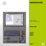
Pilot
TNC 410
NC-Software
286 060-xx
8/2000
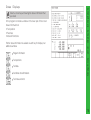
Contents
... is your concise programming guide for the HEIDENHAIN
TNC 410 contouring controls. For more comprehensive
information on programming and operating, refer to the TNC
User's Manual. There you will find complete information on:
Q-parameter programming
the central tool file
tool measurement
Certain symbols are used in the Pilot to denote specific types
of information:
Important note
Warning: danger for the user or the machine!
The TNC and the machine tool must be prepared by
the machine tool builder to perform these functions!
Chapter in User's Manual where you will find more
detailed information on the current topic.
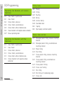
Fundamentals ...................................................................
4
Contour Approach and Departure ..................................... 1 3
Path Functions .................................................................. 1 8
FK Free Contour Programming ......................................... 2 5
Subprograms and Program Section Repeats ....................
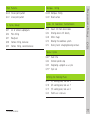
Working with Cycles .........................................................
Drilling Cycles ...................................................................
Pockets, Studs, and Slots .................................................
Point Patterns ...................................................................
SL Cycles ..........................................................................
Multipass Milling ...............................................................
Coordinate Transformation Cycles ...................................
Special Cycles ...................................................................
Contents
The Pilot
31
34
37
45
54
56
60
62
67
Digitizing 3D Surfaces ....................................................... 6 9
Graphics and Status Displays ........................................... 7 3
ISO Programming .............................................................. 7 6
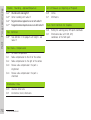
The information in this Pilot applies to the TNC 410 with the
following software number:
Control
TNC 410
Miscellaneous Functions M ............................................... 8 1
NC Software Number
286 060-xx
3
Fundamentals
Fundamentals
Programs / Files
See Programming, File Management
The TNC keeps its programs, tables and texts in files.
A file designation consists of two components:
THREAD2.H
File name
File type
Maximum length:
8 characters
see table at right
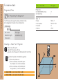
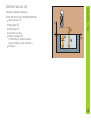
Creating a New Part Program
PGM
MGT
BLK
FORM
4
Enter new file name
Select file type via soft key
Select unit of measure for dimensions (mm or inches)
Define the blank form (BLK) for graphics:
Enter the spindle axis
Enter coordinates of the MIN point:
the smallest X, Y and Z coordinates
Enter coordinates of the MAX point:
the greatest X, Y and Z coordinates
1 BLK FORM 0.1 Z X+0 Y+0 Z-50
2 BLK FORM 0.2 X+100 Y+100 Z+0
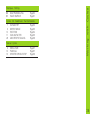
Files in the TNC
File type
Programs
in HEIDENHAIN format
in ISO format
.H
.I
Table for
Tools
Tool pockets
Datums
Points
TOOL.T
TOOLP.TCH
.D
.PNT
Fundamentals
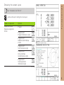
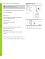
Choosing the screen layout
See Introduction, the TNC 410
Show soft keys for setting the screen layout
Mode of operation
Program run, full seq.
Program run, single block
Test run
Options
Program
Program at left
Program information at right
Program at left
Additional position display
at right
Positions
Program at left, graphics at right
Program at left
Tool information at right
Program at left
Active coordinate
transformations at right
Program at left
Tool measurement
information at right
Continued
5
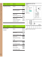
Fundamentals
Mode of operation
Options
Programming and Editing
Program
Programming graphics
Program at left
Programming graphics right
Program at left
Graphics illustrating input
parameters at right
Mode of operation
Manuell operation
Handwheel
Options
Position
Position at left
Program information at right
Position at left
Additional position display
at right
Position at left
Tool information at right
Position at left
Active coordinate
transformations at right
6
Program at left, graphic support at right
Programmable axes in an NC block
Linear motion: 5 axes
Circular motion: 2 linear axes in a plane or
3 linear axes with cycle 19 WORKING PLANE
Fundamentals
Absolute Cartesian Coordinates
The dimensions are measured from the current datum.
The tool moves to the absolute coordinates.
Incremental Cartesian Coordinates
The dimensions are measured from the last programmed position of
the tool.
The tool moves by the incremental coordinates.
7
Fundamentals
Circle Center and Pole: CC
The circle center (CC) must be entered to program circular tool
movements with the path function C (see page 21). CC is also needed
to define the pole for polar coordinates.
CC is entered in Cartesian coordinates*.
An absolutely defined circle center or pole is always measured from
the workpiece datum.
An incrementally defined circle center or pole is always measured from
the last programmed position of the workpiece.
Angle Reference Axis
Angles such as a polar coordinate angle PA or an angle of rotation
ROT are measured from the angle reference axis.
Working plane
X/Y
Y/Z
Z/X
8
Ref. axis and 0° direction
X
Y
Z
*Circle center in polar coordinates: See FK programming
Coordinates
Polar coordinate radius PR = Distance of the position from the pole
Polar coordinate angle PA = Angle from the angle reference axis to
the straight line CC PR
Incremental dimensions
Incremental dimensions in polar coordinates are measured from the
last programmed position.
Fundamentals
Polar
Dimensions in polar coordinates are referenced to the pole (CC).
A position in the working plane is defined by
Programming polar coordinates
Select the path function
Press the P key
Answer the dialog prompts
Defining Tools
Tool data
Each tool is identified with a number between 1 and 254.
Entering tool data
You can enter the tool data (length L and radius R)
in a tool table (centrally, Program TOOL.T)
or
within the part program in TOOL DEF blocks (locally)
9
Fundamentals
Tool number
Tool length L
Tool radius R
Program the tool length as its difference ∆L to the zero tool:
∆L>0: The tool is longer than the zero tool
∆L<0: The tool is shorter than the zero tool
With a tool presetter you can measure the actual tool length, then
program that length.
Calling the tool data
Tool number
Working spindle axis: tool axis
Spindle speed S
Tool length oversize DL (e.g. to compensate wear)
Tool radius oversize DR (e.g. to compensate wear)
3
4
5
6
10
TOOL DEF 6 L+7.5 R+3
TOOL CALL 6 Z S2000 DL+1 DR+0.5
L Z+100 R0 FMAX
L X-10 Y-10 R0 FMAX M6
Tool change
Beware of tool collision when moving to the tool change
position!
The direction of spindle rotation is defined by M function:
M3: Clockwise
M4: Counterclockwise
The maximum permissible oversize for tool radius or length
is ± 99.999 mm!
Oversizes on an end mill
Compensation
Fundamentals
Tool
The TNC compensates the length L and radius R of the tool during
machining.
Length compensation
Beginning of effect:
Tool movement in the spindle axis
End of effect:
Tool exchange or tool with the length L=0
Radius compensation
Beginning of effect:
Tool movement in the working plane with RR or RL
End of effect:
Execution of a positioning block with R0
S = Start; E
= End
Working without radius compensation (e.g. drilling):
Tool movement with R0
11
Fundamentals
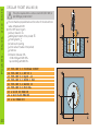
Datum Setting Without a 3D Touch Probe
During datum setting you set the TNC display to the coordinates of a
known position on the workpiece:
Insert a zero tool with known radius
Select the manual operation or
electronic handwheel mode
Touch the reference surface in the tool axis with the tool and enter
its length
Touch the reference surface in the working plane with the tool and
enter the position of the tool center
Datum Setting with a 3D Touch Probe
The fastest, simplest and most accurate way to set a datum is to use a
HEIDENHAIN 3D touch probe.
The following probe functions are provided by the manual operation
and electronic handwheel modes of operation:
Basic rotation
Datum setting in one axis
Datum setting at a corner
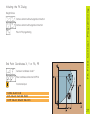
12
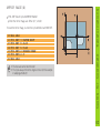
Datum setting at a circle center
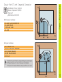
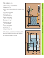
Starting point P S
PS lies outside of the contour and must be approached without radius
compensation.
Auxiliary point P H
PH lies outside of the contour and is calculated by the TNC.
The tool moves from the starting point PS to the auxiliary point
PH at the feed rate last programmed feed rate!
First contour point P A and last contour point P E
The first contour point PA is programmed in the APPR (approach) block.
The last contour point is programmed as usual.
End point P N
PN lies outside of the contour and results from the DEP (departure)
block. PN is automatically approached with R0.
Path Functions for Approach and Departure
Press the soft key with the desired path function:
Straight line with tangential connection
Straight line perpendicular to the
contour point
Contour Approach and Departure
Contour Approach and Departure
Circular arc with tangential connection
Straight line segment tangentially connected
to the contour through an arc
Program a radius compensation in the APPR block!
DEP blocks set the radius compensation to 0!
13
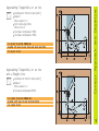
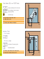
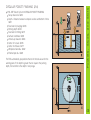
Contour Approach and Departure
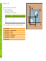
Approaching on a Straight Line with
Tangential Connection
Coordinates for the first contour point PA
Distance len (length) from PH to PA
Enter a length Len > 0
Tool radius compensation RR/RL
7 L X+40 Y+10 R0 FMAX M3
8 APPR LT X+20 Y+20 LEN 15 RR F100
9 L X+35 Y+35
Approaching on a Straight Line Perpendicular to
the First Contour Element
Coordinates for the first contour point PA
Distance len (length) from PH to PA
Enter a length Len > 0
Radius compensation RR/RL
7 L X+40 Y+10 R0 FMAX M3
8 APPR LN X+10 Y+20 LEN 15 RR F100
9 L X+20 Y+35
14
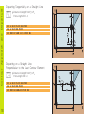
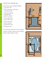
Coordinates for the first contour point PA
Radius R
Enter a radius R > 0
Circle center angle (CCA)
Enter a CCA > 0
Tool radius compensation RR/RL
Tool radius compensation RR/RL
7 L X+40 Y+10 R0 FMAX M3
8 APPR CT X+10 Y+20 CCA 180 R10 RR F100
9 L X+20 Y+35
Approaching Tangentially on an Arc
and a Straight Line
Coordinates for the first contour point PA
Radius R
Enter a radius R > 0
Tool radius compensation RR/RL
Contour Approach and Departure
Approaching Tangentially on an Arc
7 L X+40 Y+10 R0 FMAX M3
8 APPR LCT X+10 Y+20 R10 RR F100
9 L X+20 Y+35
15
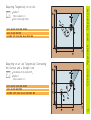
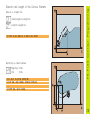
Contour Approach and Departure
16
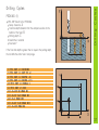
Departing Tangentially on a Straight Line
Distance len (length) from PE to PN
Enter a length LEN > 0
23 L X+30 Y+35 RR F100
24 L Y+20 RR F100
25 DEP LT LEN 12.5 F100 M2
Departing on a Straight Line
Perpendicular to the Last Contour Element
Distance len (length) from PE to PN
Enter a length LEN > 0
23 L X+30 Y+35 RR F100
24 L Y+20 RR F100
25 DEP LN LEN+20 F100 M2
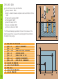
Radius R
Enter a radius R > 0
Circle center angle (CCA)
23 L X+30 Y+35 RR F100
24 L Y+20 RR F10
25 DEP CT CCA 180 R+8 F100 M2
Departing on an Arc Tangentially Connecting
the Contour and a Straight Line
Coordinates of the end point PN
Radius R
Enter a radius R > 0
23 L X+30 Y+35 RR F100
24 L Y+20 RR F100
25 DEP LCT X+10 Y+12 R8 F100 M2
Contour Approach and Departure
Departing Tangentially on an Arc
17
Path Functions
Path Functions for Positioning Blocks
See Programming: Programming contours.
Programming the Direction of Traverse
Regardless of whether the tool or the workpiece is actually moving,
you always program as if the tool is moving and the workpiece is
stationary.
Entering the Target Positions
Target positions can be entered in Cartesian or polar coordinates
either as absolute or incremental values, or with both absolute and
incremental values in the same block.
Entries in the Positioning Block
A complete positioning block contains the following data:
Path function
Coordinates of the contour element end points (target position)
Radius compensation RR/RL/R0
Feed rate F
Miscellaneous function M
Before you execute a part program, always pre-position the tool
to prevent the possibility of damaging the tool or workpiece!
Path functions
Straight line
Page 19
Chamfer between two
straight lines
Page 20
Corner
rounding
Page 20
Circle center or pole for
polar coordinates
Page 21
Circular path around the
circle center CC
Page 21
Circular path with
known radius
Page 22
Circular path with
tangential connection
previous contour
18
Free contour
programming
to
Page 23
Page 25
Coordinates of the straight line end point
Tool radius compensation RR/RL/R0
Feed rate F
Miscellaneous function M
With Cartesian coordinates:
7 L X+10 Y+40 RL F200 M3
8 L IX+20 IY-15
9 L X+60 IY-10
Path Functions
Straight Line
With polar coordinates:
12
13
14
15
16
CC
LP
LP
LP
LP
X+45 Y+25
PR+30 PA+0 RR F300 M3
PA+60
IPA+60
PA+180
You must first define the pole CC before you can program
polar coordinates!
Program the pole CC only in Cartesian coordinates!
The pole CC remains effective until you define a new one!
19
Path Functions
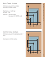
Inserting a Chamfer Between Two Straight Lines
Chamfer Side Length
7 L X+0 Y+30 RL F300 M3
8 L X+40 IY+5
9 CHF 12
10 L IX+5 Y+0
You cannot start a contour with a CHF block!
The radius compensation before and after the CHF block
must be the same!
An inside chamfer must be large enough to accommodate
the current tool!
Corner Rounding
The beginning and end of the arc extend tangentially from the previous
and subsequent contour elements.
Radius R of the circular arc
Feed rate F for corner rounding
5
6
7
8
20
L X+10
L X+40
RND R5
L X+10
Y+40 RL F300 M3
Y+25
F100
Y+5
An inside arc must be large enough to accommodate the
current tool!
Coordinates of the circle center CC
Coordinates of the arc end point
Direction of rotation DR
C and CP enable you to program a complete circle in one block.
With Cartesian coordinates:
5 CC X+25 Y+25
6 L X+45 Y+25 RR F200 M3
7 C X+45 Y+25 DR+
Path Functions
Circular Path Around the Circle Center CC
With polar coordinates:
18 CC X+25 Y+25
19 LP PR+20 PA+0 RR F250 M3
20 CP PA+180 DR+
Define the pole CC before programming polar coordinates!
Program the pole CC only in Cartesian coordinates!
The pole CC remains effective until you define a new one!
The arc end point can be defined only with the polar
coordinate angle (PA)!
21
Path Functions
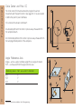
Circular Path with Known Radius (CR)
Coordinates of the arc end point
Radius R
If the central angle ZW > 180, R is negative.
If the central angle ZW < 180, R is positive.
Direction of rotation DR
10 L X+40 Y+40 RL F200 M3
11 CR X+70 Y+40 R+20 DR-
Arc starting point
Arc 1 or
11 CR X+70 Y+40 R+20 DR+
Arc 2
Arcs
22
10 L X+40 Y+40 RL F200 M3
11 CR X+70 Y+40 R-20 DR-
Arc starting point
Arc 3 or
11 CR X+70 Y+40 R-20 DR+
Arc 4
1
and
2
Arcs
3
and
4
Coordinates of the arc end point
Radius compensation RR/RL/R0
Feed rate F
Miscellaneous function M
With Cartesian coordinates:
5
6
7
8
L X+0 Y+25 RL F250 M3
L X+25 Y+30
CT X+45 Y+20
L Y+0
Path Functions
Circular Path CT with Tangential Connection
With polar coordinates:
12
13
14
15
16
CC X+40 Y+35
L X+0 Y+35 RL F250 M3
LP PR+25 PA+120
CTP PR+30 PA+30
L Y+0
Define the pole CC before programming polar coordinates!
Program the pole CC only in Cartesian coordinates!
The pole CC remains effective until you define a new one!
23
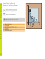
Path Functions
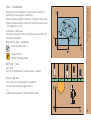
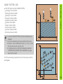
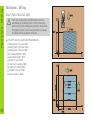
Helix (Only in Polar Coordinates)
Calculations (upward milling direction)
Path revolutions:
n = Thread revolutions + overrun at start and
end of thread
Total height:
h = Pitch P x path revolutions n
Incr. coord. angle:
IPA = Path revolutions n x 360°
Start angle:
PA = Angle at start of thread + angle for
overrun
Start coordinate:
Z = Pitch P x (thread revolutions + thread
overrun at start of thread)
Shape of helix
Internal thread Work direction
Right-hand
Left-hand
Right-hand
Left-hand
Direction
Radius comp.
Z+
Z+
Z
Z
DR+
DR
DR
DR+
RL
RR
RR
RL
Z+
Z+
Z
Z
DR+
DR
DR
DR+
RR
RL
RL
RR
External thread
Right-hand
Left-hand
Right-hand
Left-hand
M6 x 1 mm thread with 5 revolutions :
24
12
13
14
15
CC X+40 Y+25
L Z+0 F100 M3
LP PR+3 PA+270 RL
CP IPA-1800 IZ+5 DR- RL F50
See Programming Tool Movements FK Free Contour
Programming
If the end point coordinates are not given in the workpiece drawing
or if the drawing gives dimensions that cannot be entered with the
gray path function keys, you can still program the part by using the
FK Free Contour Programming.
Possible data on a contour element:
Known coordinates of the end point
Auxiliary point on the contour element
Auxiliary point near the contour element
Directional data (angle) / position data
Data regarding the course of the contour
To use FK programming properly:
All contour elements must lie in the working plane.
Enter all available data on each contour element.
If a program contains both FK and conventional blocks, the FK
contour must be fully defined before you can return to conventional
programming.
These dimensions can be programmed with FK
FK Free Contour Programming
FK Free Contour Programming
25
FK Free Contour Programming
Working with the Interactive Graphics
Select the PGM+GRAPHICS screen layout!
The interactive graphics show the contour as you are programming it.
If the data you enter can apply to more than one solution, the following
soft keys will appear:
To show the possible solutions
To enter the displayed solution in the part program
To enter data for subsequent contour elements
To graphically display the next programmed block
Standard colors of the interactive graphics
Fully defined contour element
The displayed element is one of a limited number of
possible solutions
The element is one of an infinite number of solutions
Contour element from a subprogram
26
Straight Circular
Contour element without tangential connection
Contour element with tangential connection
Pole for FK programming
End Point Coordinates X, Y or PA, PR
Cartesian coordinates X and Y
Polar coordinates referenced to FPOL
FK Free Contour Programming
Initiating the FK Dialog
Incremental input
7 FPOL X+20 Y+30
8 FL IX+10 Y+20 RR F100
9 FCT PR+15 IPA+30 DR+ R15
27
FK Free Contour Programming
Circle Center (CC) in an FC/ FCT block
Cartesian coordinates of the circle center
Polar coordinates of the circle center
referenced to FPOL
Incremental input
10 FC CCX+20 CCY+15 DR+ R15
11 FPOL X+20 Y+15
...
13 FC DR+ R15 CCPR+35 CCPA+40
Auxiliary
Point
... P1 on a contour
... PD next to a contour
Coordinates of the auxiliary points
Perpendicular distance
13 FC DR- R10 P1X+42.929 P1Y+60.071
14 FLT AN-70 PDX+50 PDY+53 D10
28
Data on a straight line
Gradient angle of a straight line
Length of a straight line
27 FLT X+25 LEN 12.5 AN+35 RL F200
Identifying a closed contour
Beginning: CLSD+
End:
CLSD
12 L X+5 Y+35 RL F500 M3
13 FC DR- R15 CLSD+ CCX+20 CCY+35
...
17 FCT DR- R+15 CLSD-
FK Free Contour Programming
Direction and Length of the Contour Element
29
FK Free Contour Programming
30
Values Relative to Block N:
Distance of the Contour Element
Parallel to a straight contour element
Parallel to the entry tangent of an arc
Distance from a parallel element
Always enter relative values incrementally!
17
18
19
20
21
FL LEN 20 AN+15
FL AN+105
FL LEN 12.5 PAR 17 DP 12.5
FSELECT 2
FL LEN 20 IAN+95
Subprograms
Subprograms and Program Section
Repeats
Subprograms and program section repeats enable you to program a
machining sequence once and then run it as often as needed.
Working with Subprograms
1 The main program runs up to the subprogram call CALL LBL1.
2 The subprogram labeled with LBL1 runs through to its end LBL0.
3 The main program resumes.
It's good practice to place subprograms after the main program
end (M2).
Answer the dialog prompt REP with the NOENT key!
You cannot call LBL0!
S = Jump; R = Return jump
Working with Program Section Repeats
1 The main program runs up to the call for a section repeat CALL
2
3
LBL1 REP2/2.
The program section between LBL1 and CALL LBL1 REP2/2 is
repeated the number of times indicated with REP.
After the last repetition the main program resumes.
Altogether, the program section is run once more than the
number of programmed repeats!
31
Subprograms
32
Subprogram Nesting:
A Subprogram within a Subprogram
1
2
3
4
5
The main program runs up to the first subprogram call CALL LBL1.
Subprogram 1 runs up to the second subprogram call CALL LBL2.
Subprogram 2 runs to its end.
Subprogram 1 resumes and runs to its end.
The main program resumes.
A subprogram cannot call itself!
Subprograms can be nested up to a maximum depth
of 8 levels!
S = Jump; R = Return jump
Subprograms
Any Program as a Subprogram
1 The calling program A runs up to the program call CALL PGM B.
2 The called program B runs through to its end.
3 The calling program A resumes.
The called program must not end with M2 or M30!
S = Jump; R = Return jump
33
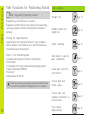
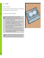
Working with Cycles
Working with Cycles
Certain frequently needed machining sequences are stored in the TNC
as cycles. Coordinate transformations and some special functions are
also available as cycles.
In a cycle, positioning data entered in the tool axis are
always incremental, even without the I key!
The algebraic sign of the cycle parameter DEPTH determines
the working direction!
1
200
201
202
203
204
2
17
PECKING
DRILLING
REAMING
BORING
UNIVERSAL DRILLING
COUNTERBORE BACK
TAPPING
RIGID TAPPING
Page 37
Page 38
Page 39
Page 40
Page 41
Page 42
Page 43
Page 44
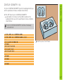
Pockets, Studs, and Slots
Example
6 CYCL
7 CYCL
8 CYCL
9 CYCL
...
DEF
DEF
DEF
DEF
1.0
1.1
1.2
1.3
PECKING
SET UP 2
DEPTH -15
PECKG 10
Feed rates are entered in mm/min, the dwell time in seconds.
Defining cycles
Select the desired cycle:
Select the cycle group
Select the cycle
34
Drilling Cycles
4
212
213
5
214
215
3
210
211
POCKET MILLING
POCKET FINISHING
STUD FINISHING
CIRCULAR POCKET MILLING
CIRCULAR POCKET FINISHING
CIRCULAR STUD FINISHING
SLOT MILLING
SLOT WITH RECIP. PLUNGE
CIRCULAR SLOT
Page
Page
Page
Page
Page
Page
Page
Page
Page
45
46
47
48
49
50
51
52
53
Point Patterns
220
221
CIRCULAR PATTERN
LINEAR PATTERN
Page 54
Page 55
SL Cycles
14
15
6
16
CONTOUR GEOMETRY
PILOT DRILLING
ROUGH-OUT
CONTOUR MILLING
Page
Page
Page
Page
57
58
58
59
Continued on next page
230
231
Milling
MULTIPASS MILLING
RULED SURFACE
Page 60
Page 61
Cycles for Coordinate Transformations
7
8
10
11
26
DATUM SHIFT
MIRROR IMAGE
ROTATION
SCALING FACTOR
AXIS-SPECIFIC SCALING
Page 62
Page 63
Page 64
Page 65
Page 66
Special Cycles
9
12
13
DWELL TIME
PGM CALL
ORIENTED SPINDLE STOP
Page 67
Page 67
Page 68
Working with Cycles
Multipass
35
Working with Cycles
Graphic Support During Cycle Programming
Select the PGM+FIGURE screen layout!
As you create a program, the TNC provides you with graphic illustrations of the input parameters.
Calling a Cycle
The following cycles are effective as soon as they are defined:
Cycles for coordinate transformations
DWELL TIME cycle
The SL cycle CONTOUR GEOMETRY
Point patterns
All other cycles go into effect when they are called through
CYCL CALL: effective for one block
M99: effective for one block
M89: effective until canceled (depends on machine parameter
settings)
All machining cycles can also be called up in conjunction with point
tables. For this, use the function CYCL CALL PAT (see Users Manual)
36
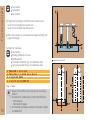
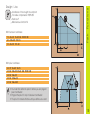
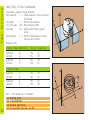
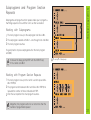
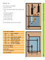
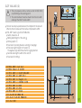
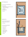
PECKING (1)
CYCL DEF: Select Cycle 1 PECKING
Set-up clearance: A
Total hole depth (distance from the workpiece surface to the
bottom of the hole): B
Pecking depth: C
Dwell time in seconds
Feed rate F
Drilling Cycles
Drilling Cycles
If the Total hole depth is greater than or equal to the pecking depth,
the tool drills the entire hole in one plunge.
6 CYCL DEF 1.0 PECKING
7 CYCL DEF 1.1 SET UP +2
8 CYCL DEF 1.2 DEPTH -15
9 CYCL DEF 1.3 PECKG +7.5
10 CYCL DEF 1.4 DWELL 1
11 CYCL DEF 1.5 F80
12 L Z+100 R0 FMAX M6
13 L X+30 Y+20 FMAX M3
14 L Z+2 FMAX M99
15 L X+80 Y+50 FMAX M99
16 L Z+100 FMAX M2
37
Drilling Cycles
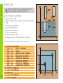
DRILLING (200)
CYCL DEF: Select Cycle 200 DRILLING
Set-up clearance: Q200
Depth distance between workpiece surface and bottom of hole:
Q201
Feed rate for plunging: Q206
Pecking depth: Q202
Dwell time at top: Q210
Surface coordinate: Q203
2nd set-up clearance: Q204
The TNC automatically pre-positions the tool in the tool axis. If the
depth is greater than or equal to the pecking depth, the tool drills to
the depth in one plunge.
11 CYCL DEF 200 DRILLING
Q200 = 2
;SET-UP CLEARANCE
Q201 = -15
;DEPTH
Q206 = 250
;FEED RATE FOR PLUNGING
Q202 = 5
;PECKING DEPTH
Q210 = 0
;DWELL TIME AT TOP
Q203 = +0
;SURFACE COORDINATE
Q204 = 100
;2ND SET-UP CLEARANCE
12 L Z+100 R0 FMAX M6
13 L X+30 Y+20 FMAX M3
14 CYCL CALL
15 L X+80 Y+50 FMAX M99
16 L Z+100 FMAX M2
38
CYCL DEF: Select Cycle 201 REAMING
Set-up clearance: Q200
Depth distance between workpiece surface and bottom of hole:
Q201
Feed rate for plunging: Q206
dwell time at depth: Q211
Retraction feed rate: Q208
Surface coordinate: Q203
2nd set-up clearance: Q204
Drilling Cycles
REAMING (201)
The TNC automatically pre-positions the tool in the tool axis.
11 CYCL DEF 201 REAMING
Q200 = 2
;SET-UP CLEARANCE
Q201 = -15
;DEPTH
Q206 = 100
;FEED RATE FOR PLUNGING
Q211 = 0.5
;DWELL TIME AT DEPTH
Q208 = 250
;RETRACTION FEED RATE
Q203 = +0
;SURFACE COORDINATE
Q204 = 100
;2ND SET-UP CLEARANCE
12 L Z+100 R0 FMAX M6
13 L X+30 Y+20 FMAX M3
14 CYCL CALL
15 L X+80 Y+50 FMAX M99
16 L Z+100 FMAX M2
39
Drilling Cycles
BORING (202)
Danger of collision! Choose a disengaging direction that
moves the tool away from the wall of the hole.
CYCL DEF: Select Cycle 202 BORING
Set-up clearance: Q200
Depth distance between workpiece surface and bottom of hole:
Q201
Feed rate for plunging: Q206
Dwell time at depth: Q211
Retraction feed rate: Q208
Surface coordinate: Q203
2nd set-up clearance: Q204
Disengaging direction (0/1/2/3/4) at bottom of hole: Q214
The TNC automatically pre-positions the tool in the tool axis.
40
11 CYCL DEF 202 BORING
Q200 = 2
;SET-UP CLEARANCE
Q201 = -15
;DEPTH
Q206 = 100
;FEED RATE FOR PLUNGING
Q211 = 0.5
;DWELL TIME AT DEPTH
Q208 = 250
;RETRACTION FEED RATE
Q203 = +0
;SURFACE COORDINATE
Q204 = 100
;2ND SET-UP CLEARANCE
Q214 = 1Di
;DISENGAGING DIRECTION
12 L Z+100 R0 FMAX M6
13 L X+30 Y+20 FMAX M3
14 CYCL CALL
15 L X+80 Y+50 FMAX M99
16 L Z+100 FMAX M2
CYCL DEF: Select Cycle 203 UNIVERSAL DRILLING
Set-up clearance: Q200
Depth distance between workpiece surface and bottom of hole:
Q201
Feed rate for plunging: Q206
Pecking depth: Q202
Dwell time at top: Q210
Surface coordinate: Q203
2nd set-up clearance: Q204
Decrement after each pecking depth: Q212
Nr of breaks number of chip breaks before retraction: Q213
min. pecking depth if a decrement has been entered: Q205
Dwell time at depth: Q211
Retraction feed rate: Q208
Drilling Cycles
UNIVERSAL DRILLING (203)
The TNC automatically pre-positions the tool in the tool axis. If the
depth is greater than or equal to the pecking depth, the tool drills to
the depth in one plunge.
41
Drilling Cycles
COUNTERBORE BACK (204)
CYCL DEF: Select Cycle 204 COUNTERBORE BACK
Set-up clearance: Q200
Depth of counterbore: Q249
Material thickness: Q250
Tool edge off-center distance: Q251
Tool edge height: Q252
Feed rate for pre-positioning: Q253
Feed rate for counterboring: Q254
Dwell time at counterbore floor: Q255
Workpiece surface coordinate: Q203
2nd set-up clearance: Q204
Disengaging direction (0/1/2/3/4): Q214
Danger of collision! Select the disengaging direction that
gets the tool clear of the counterbore floor!
Use this cycle only with a reverse boring bar!
11 CYCL
Q200
Q249
Q250
Q251
Q252
Q253
Q254
Q255
Q203
Q204
Q214
42
DEF 204 COUNTERBORE BACK
= 2
;SET-UP CLEARANCE
= +5
;DEPTH OF COUNTERBORE
= 20
;MATERIAL THICKNESS
= 3.5 ;OFF-CENTER DISTANCE
= 15
;TOOL EDGE HEIGHT
= 750 ;F PRE-POSITIONING
= 200 ;F COUNTERBORING
= 0.5 ;DWELL TIME
= +0
;SURFACE COORDINATE
= 50
;2ND SET-UP CLEARANCE
= 1
;DISENGAGING DIRECTN
Insert the floating tap holder
CYCL DEF: Select cycle 2 TAPPING
Set-up clearance: A
Total hole depth (thread length = distance between the
workpiece surface and the end of the thread): B
Dwell time in seconds (a value between 0 and 0.5 seconds)
Feed rate F = Spindle speed S x thread pitch P
For tapping right-hand threads, actuate the spindle with M3,
for left-hand threads use M4!
25
26
27
28
29
30
31
32
Drilling Cycles
TAPPING with Floating Tap Holder (2)
CYCL DEF 2.0 TAPPING
CYCL DEF 2.1 SET UP 3
CYCL DEF 2.2 DEPTH -20
CYCL DEF 2.3 DWELL 0.4
CYCL DEF 2.4 F100
L Z+100 R0 FMAX M6
L X+50 Y+20 FMAX M3
L Z+3 FMAX M99
43
Drilling Cycles
44
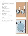
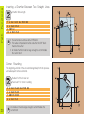
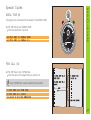
RIGID TAPPING (17)
Machine and TNC must be prepared by the machine tool
builder to perform rigid tapping!
In rigid tapping, the spindle speed is synchronized with the
tool axis feed rate!
CYCL DEF: Select cycle 17 RIGID TAPPING
Set-up clearance: A
Tapping depth (distance between workpiece surface and end
of thread): B
Pitch: C
The algebraic sign determines the direction of the thread:
Right-hand thread: +
Left-hand thread:
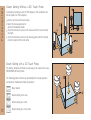
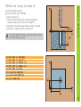
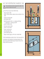
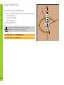
POCKET MILLING (4)
This cycle requires either a center-cut end mill (ISO 1641) or
pilot drilling at the pocket center!
The tool begins milling in the positive axis direction of the longer side.
In square pockets it moves in the positive Y direction.
The tool must be pre-positioned over the center of the slot with tool
radius compensation R0
CYCL DEF: Select cycle 4 POCKET MILLING
Set-up clearance: A
Milling depth (depth of the pocket): B
Pecking depth: C
Feed rate for pecking
First side length (length of the pocket, parallel to the first main
axis of the working plane): D
Second side length (width of pocket, sign always positive): E
Feed rate
Rotation clockwise: DR
Climb milling with M3: DR+
Up-cut milling with M3: DR
12
13
14
15
16
17
18
19
20
21
CYCL DEF 4.0 POCKET MILLING
CYCL DEF 4.1 SET UP2
CYCL DEF 4.2 Depth-10
CYCL DEF 4.3 PECKG4 F80
CYCL DEF 4.4 X80
CYCL DEF 4.5 Y40
CYCL DEF 4.6 F100 DR+
L Z+100 R0 FMAX M6
L X+60 Y+35 FMAX M3
L Z+2 FMAX M99
Pockets, Studs, and Slots
Pockets, Studs, and Slots
45
Pockets, Studs, and Slots
46
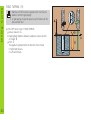
POCKET FINISHING (212)
CYCL DEF: Select Cycle 212 POCKET FINISHING
Set-up clearance: Q200
Depth Distance between workpiece surface and bottom of
hole: Q201
Feed rate for plunging: Q206
Pecking depth: Q202
Feed rate for milling: Q207
Surface coordinate: Q203
2nd set-up clearance: Q204
Center in 1st axis: Q216
Center in 2nd axis: Q217
First side length: Q218
Second side length: Q219
Corner radius: Q220
Allowance in 1st axs: Q221
The TNC automatically pre-positions the tool in the tool axis and in the
working plane. If the depth is greater than or equal to the pecking
depth, the tool drills to the depth in one plunge.
CYCL DEF: Select Cycle 213 STUD FINISHING
Set-up clearance: Q200
Depth Distance between workpiece surface and bottom of hole:
Q201
Feed rate for plunging: Q206
Pecking depth: Q202
Feed rate for milling: Q207
Surface coordinate: Q203
2nd set-up clearance: Q204
Center in 1st axis: Q216
Center in 2nd axis: Q217
First side length: Q218
Second side length: Q219
Corner radius: Q220
Allowance in 1st axs: Q221
The TNC automatically pre-positions the tool in the tool axis and in the
working plane. If the depth is greater than or equal to the pecking
depth, the tool drills to the depth in one plunge.
Pockets, Studs, and Slots
STUD FINISHING (213)
47
Pockets, Studs, and Slots
48
CIRCULAR POCKET MILLING (5)
This cycle requires either a center-cut end mill (ISO 1641) or
pilot drilling at pocket center!
The tool must be pre-positioned over the center of the slot with tool
radius compensation R0
CYCL DEF: Select cycle 5
Set-up clearance: A
Milling depth (depth of the pocket): B
Pecking depth: C
Feed rate for pecking
Circle radius R (radius of the pocket)
Feed rate
Rotation clockwise: DR
Climb milling with M3: DR+
Up-cut milling with M3: DR
17
18
19
20
21
22
23
24
25
CYCL DEF 5.0 CIRCULAR POCKET
CYCL DEF 5.1 SET UP 2
CYCL DEF 5.2 Depth -12
CYCL DEF 5.3 PECKG 6 F80
CYCL DEF 5.4 RADIUS 35
CYCL DEF 5.5 F100 DR+
L Z+100 R0 FMAX M6
L X+60 Y+50 FMAX M3
L Z+2 FMAX M99
CYCL DEF: Select Cycle 214 CIRCULAR POCKET FINISHING
Set-up clearance: Q200
Depth Distance between workpiece surface and bottom of hole:
Q201
Feed rate for plunging: Q206
Pecking depth: Q202
Feed rate for milling: Q207
Surface coordinate: Q203
2nd set-up clearance: Q204
Center in 1st axis: Q216
Center in 2nd axis: Q217
Workpiece blank dia.: Q222
Finished part dia.: Q223
The TNC automatically pre-positions the tool in the tool axis and in the
working plane. If the depth is greater than or equal to the pecking
depth, the tool drills to the depth in one plunge.
Pockets, Studs, and Slots
CIRCULAR POCKET FINISHING (214)
49
Pockets, Studs, and Slots
50
CIRCULAR STUD FINISHING (215)
CYCL DEF: Select Cycle 215 CIRCULAR STUD FINISHING
Set-up clearance: Q200
depth Distance between workpiece surface
and bottom of hole: Q201
Feed rate for plunging: Q206
Pecking depth: Q202
Feed rate for milling: Q207
Surface coordinate: Q203
2nd set-up clearance: Q204
Center in 1st axis: Q216
Center in 2nd axis: Q217
Workpiece blank dia.: Q222
Finished part dia.: Q223
The TNC automatically pre-positions the tool in the tool axis and in the
working plane. If the Depth is greater than or equal to the PECKING
Depth, the tool drills to the Depth in one plunge.
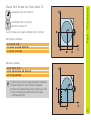
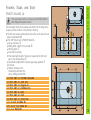
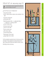
This cycle requires either a center-cut end mill (ISO 1641)
or pilot drilling at the starting point!
The cutter diameter must be smaller than the slot width
and larger than half the slot width!
The tool must be pre-positioned over the midpoint of the slot and
offset by the tool radius with tool radius compensation at R0
CYCL DEF: Select cycle 3 SLOT MILLING
Safety clearance: A
Milling depth (depth of the slot): B
Pecking depth: C
Feed rate for pecking (traverse velocity for plunging)
First side length? (length of the slot): D
The algebraic sign determines the first cutting direction
Second side length? (width of the slot): E
Feed rate (for milling)
10
11
12
13
14
15
16
17
18
19
20
21
TOOL DEF 1 L+0 R+6
TOOL CALL 1 Z S1500
CYCL DEF 3.0 SLOT MILLING
CYCL DEF 3.1 SET UP 2
CYCL DEF 3.2 Depth -15
CYCL DEF 3.3 PECKG 5 F80
CYCL DEF 3.4 X50
CYCL DEF 3.5 Y15
CYCL DEF 3.6 F120
L Z+100 R0 FMAX M6
L X+16 Y+25 R0 FMAX M3
L Z+2 M99
Pockets, Studs, and Slots
SLOT MILLING (3)
51
Pockets, Studs, and Slots
SLOT WITH RECIPROCATING PLUNGE-CUT (210)
The cutter diameter must be no larger than the width of the
slot, and no smaller than one third!
CYCL DEF: Select Cycle 210 SLOT RECIP. PLNG
Set-up clearance: Q200
Depth Distance between workpiece surface and bottom of hole:
Q201
Feed rate for milling: Q207
Pecking depth: Q202
Machining operation (0/1/2) 0 = roughing and finishing,
1 = roughing only, 2 = finishing only: Q215
Surface coordinate: Q203
2nd set-up clearance: Q204
Center in 1st axis: Q216
Center in 2nd axis: Q217
First side length: Q218
Second side length: Q219
Angle of rotation (angle by with the slot is rotated): Q224
The TNC automatically pre-positions the tool in the tool axis and in the
working plane. During roughing the tool plunges obliquely into the
metal in a back-and-forth motion between the ends of the slot. Pilot
drilling is therefore unnecessary.
52
The cutter diameter must be no larger than the width of the
slot, and no smaller than one third!
CYCL DEF: Select Cycle 211 CIRCULAR SLOT
Set-up clearance: Q200
Depth Distance between workpiece surface and bottom of hole:
Q201
Feed rate for milling: Q207
Pecking depth: Q202
Machining operation (0/1/2) 0 = roughing and finishing,
1 = roughing only, 2 = finishing only: Q215
Surface coordinate: Q203
2nd set-up clearance: Q204
Center in 1st axis: Q216
Center in 2nd axis: Q217
Pitch circle dia.: Q244
Second side length: Q219
Starting angle of the slot: Q245
Angular length of the slot: Q248
Pockets, Studs, and Slots
CIRCULAR SLOT with reciprocating plunge (211)
The TNC automatically pre-positions the tool in the tool axis and in the
working plane. During roughing the tool plunges obliquely into the
metal in a back-and-forth helical motion between the ends of the slot.
Pilot drilling is therefore unnecessary.
53
Point Patterns
Point Patterns
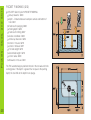
CIRCULAR PATTERN (220)
CYCL DEF: Select Cycle 220 CIRCULAR PATTERN
Center in 1st axis: Q216
Center in 2nd axis: Q217
Angle of rotation: Q244
Starting angle: Q245
Stopping angle: Q246
Stepping angle: Q247
Nr or repetitions: Q241
Set-up clearance: Q200
Surface coordinate: Q203
2nd set-up clearance: Q204
Cycle 220 POLAR PATTERN is effective immediately upon
definition!
Cycle 220 automatically calls the last defined fixed cycle!
Cycle 220 can be combined with Cycles 1, 2, 3, 4, 5, 17,
200, 201, 202, 203, 204, 212, 213, 214, 215
In combined cycles, the SET-UP CLEARANCE, SURFACE
COORDINATE and 2ND SET-UP CLEARANCE are always
taken from Cycle 220!
The TNC automatically pre-positions the tool in the tool axis and in the
working plane.
54
CYCL DEF: Select Cycle 221 LINEAR PATTERN
Starting pnt 1st axis: Q225
Starting pnt 2nd axis: Q226
Spacing in 1st axis: Q237
Spacing in 2nd axis: Q238
Number of columns: Q242
Number of lines: Q243
Angle of rotation: Q224
Set-up clearance: Q200
Surface coordinate: Q203
2nd set-up clearance: Q204
Point Patterns
LINEAR PATTERN (221)
Cycle 221 LINEAR PATTERN is effective immediately upon
definition!
Cycle 221 automatically calls the last defined fixed cycle!
Cycle 221 can be combined with Cycles 1, 2, 3, 4, 5, 17, 200,
201, 202, 203, 204, 212, 213, 214, 215
In combined cycles, the SET-UP CLEARANCE, SURFACE
COORDINATE and 2ND SET-UP CLEARANCE are always
taken from Cycle 221!
The TNC automatically pre-positions the tool in the tool axis and in the
working plane.
55
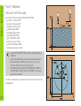
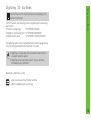
SL Cycles
SL Cycles
General Information
SL cycles are useful when you wish to machine a contour consisting of
several subcontours (up to 12 islands or pockets).
The subcontours are defined in subprograms.
When working with subcontours, always remember:
For a pocket the tool machines an inside contour, for an
island it is an outside contour!
Tool approach and departure as well as infeed in the
tool axis cannot be programmed in SL cycles!
Each contour listed in Cycle 14 CONTOUR GEOMETRY
must be a closed contour!
There is a limit to the amount of memory an SL cycle can
occupy! A maximum of 128 straight line blocks, for example,
can be programmed in an SL cycle.
Make a graphic test run before actually machining a part. That
way you can be sure that you defined the contour correctly!
56
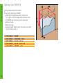
SL Cycles
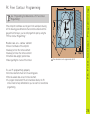
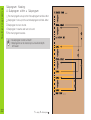
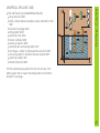
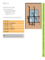
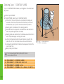
CONTOUR GEOMETRY (14)
In Cycle 14 CONTOUR GEOMETRY you list the subprograms that you
wish to superimpose to make a complete closed contour.
CYCL DEF: Select Cycle 14 CONTOUR GEOMETRY
Label numbers for contour: List the LABEL numbers of the
subprograms that you wish to superimpose to make a complete
closed contour.
Cycle 14 CONTOUR GEOMETRY is effective immediately
upon definition!
4 CYCL DEF 14.0 CONTOUR GEOM
5 CYCL DEF 14.1 CONTOUR LABEL 1/2/3
...
36 L Z+200 R0 FMAX M2
37 LBL1
38 L X+0 Y+10 RR
39 L X+20 Y+10
40 CC X+50 Y+50
...
45 LBL0
46 LBL2
...
58 LBL0
A
and
B are pockets, C
and
D islands
57
SL Cycles
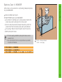
PILOT DRILLING (15)
CYCL DEF: Select cycle 15 PILOT DRILLING
Set-up clearance
Total hole depth Distance from the top surface of the
workpiece to the hole bottom
Pecking depth
Finishing allowance D
Feed rate F
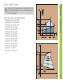
ROUGH-OUT (6)
There are two steps in the rough-out cycle:
1. Milling a channel around subcontours
2. Area clearance
58
CYCL DEF: Select Cycle 6 ROUGH-OUT
Set-up clearance: A
Milling depth: B
Pecking depth: C
Feed rate for pecking
Finishing allowance: D
Rough-out angle
Feed rate F
Finishing the individual subcontours.
CYCL DEF: Select Cycle 16 CONTOUR MILLING
Set-up clearance: A
Milling depth: B
Pecking depth: C
Feed rate for pecking
Rotation clockwise: DR
Climb milling for pocket and island:
Up-cut milling for pocket and island: +
Feed rate F
SL Cycles
CONTOUR MILLING (16)
59
Multipass Milling
60
Multipass Milling
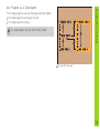
MULTIPASS MILLING (230)
From the current position, the TNC positions the tool
automatically at the starting point of the first machining
operation, first in the working plane and then in the tool axis.
Pre-position the tool in such a way that there is no danger
of collision with the workpiece or fixtures.
CYCL DEF: Select Cycle 230 MULTIPASS MILLING
Starting point in 1st axis: Q225
Starting point in 2nd axis: Q226
Starting point in 3rd axis: Q227
First side lengthIRST: Q218
Second side length: Q219
Number of cuts: Q240
Feed rate for plunging: Q206
Feed rate for milling: Q207
Stepover feed rate: Q209
Set-up clearance: Q200
Starting from the initial position, the TNC positions the tool
at the starting point (point 1), first in the working plane and
then in the tool axis.
CYCL DEF: Select Cycle 231 RULED SURFACE
Starting point in 1st axis: Q225
Starting point in 2nd axis: Q226
Starting point in 3rd axis: Q227
2nd point in 1st axis: Q228
2nd point in 2nd axis: Q229
2nd point in 3rd axis: Q230
3rd point in 1st axis: Q231
3rd point in 2nd axis: Q232
3rd point in 3rd axis: Q233
4th point in 1st axis: Q234
4th point in 2nd axis: Q235
4th point in 3rd axis: Q236
Number of cuts: Q240
Feed rate for milling: Q207
Multipass Milling
RULED SURFACE (231)
61
Transformations
Cycles for Coordinate
62
Cycles for Coordinate
Transformation
Cycles for coordinate transformation permit contours to be
Shifted
Mirrored
Rotated (in the plane)
Enlarged or reduced
Cycle
Cycle
Cycle
Cycle
7
8
10
11
DATUM SHIFT
MIRROR IMAGE
ROTATION
SCALING
Cycles for coordinate transformation are effective upon definition until
they are reset or redefined. The original contour should be defined in a
subprogram. Input values can be both absolute and incremental.
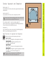
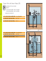
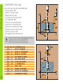
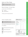
DATUM SHIFT (7)
CYCL DEF: Select Cycle 7 DATUM SHIFT
Enter the coordinates of the new datum or the number of the
datum from the datum table.
To cancel a datum shift: Re-enter the cycle definition with the input
value 0.
9 CALL LBL1
10 CYCL DEF 7.0 DATUM SHIFT
11 CYCL DEF 7.1 X+60
12 CYCL DEF 7.2 Y+40
13 CALL LBL1
Call the part subprogram
Call the part subprogram
When combining transformations, the datum shift must be
programmed before the other transformations!
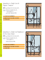
To reset the mirror image, re-enter the cycle definition with NO ENT.
15
16
17
18
19
20
21
CALL
CYCL
CYCL
CYCL
CYCL
CYCL
CALL
LBL1
DEF 7.0
DEF 7.1
DEF 7.2
DEF 8.0
DEF 8.1
LBL1
DATUM SHIFT
X+60
Y+40
MIRROR IMAGE
Y
The tool axis cannot be mirrored!
The cycle always mirrors the original contour (in this example
in subprogram LBL1)!
Transformations
CYCL DEF: Select Cycle 8 MIRROR IMAGE
Enter the mirror image axis: Either X, Y, or both
Cycles for Coordinate
MIRROR IMAGE (8)
63
Transformations
Cycles for Coordinate
64
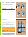
Rotation (10)
CYCL DEF: Select Cycle 10 ROTATION
Enter the rotation angle:
Input range 360° to +360°
Reference axes for the rotation angle
Working plane
X/Y
Y/Z
Z/X
Reference axis and 0° direction
X
Y
Z
To reset a ROTATION, re-enter the cycle with the rotation angle 0.
12
13
14
15
16
17
18
CALL
CYCL
CYCL
CYCL
CYCL
CYCL
CALL
LBL1
DEF 7.0 DATUM SHIFT
DEF 7.1 X+60
DEF 7.2 Y+40
DEF 10.0 ROTATION
DEF 10.1 ROT+35
LBL1
To cancel the SCALING, re-enter the cycle definition with SCL1.
11
12
13
14
15
16
17
CALL
CYCL
CYCL
CYCL
CYCL
CYCL
CALL
LBL1
DEF 7.0 DATUM SHIFT
DEF 7.1 X+60
DEF 7.2 Y+40
DEF 11.0 SCALING
DEF 11.1 SCL 0.75
LBL1
SCALING can be effective in the working plane only or in all
three main axes (depending on machine parameter 7410)!
Transformations
CYCL DEF: Select Cycle 11 SCALING
Enter the scaling factor (SCL):
Input range 0.000001 to 99.999999:
To reduce the contour ... SCL < 1
To enlarge the contour ... SCL > 1
Cycles for Coordinate
SCALING (11)
65
Transformations
Cycles for Coordinate
66
AXIS-SPECIFIC SCALING (26)
CYCL DEF: Select Cycle 20 AXIS-SPEC. SCALING
AXIS and FACTOR: Coordinate axes and factors for extending or
compressing contour dimensions
CENTERPOINT COORD. OF EXTENSION: Center of the extension
or compression
To cancel the AXIS-SPEC. SCALING, re-enter the cycle definition
assigning the factor 1 to the affected axes.
Coordinate axes sharing coordinates for arcs must be
extended or compressed by the same scaling factor!
25
26
27
28
CALL
CYCL
CYCL
CALL
LBL1
DEF 26.0 AXIS-SPEC. SCALING
DEF 26.1 X 1.4 Y 0.6 CCX+15 CCY+20
LBL1
DWELL TIME (9)
The program run is interrupted for the duration of the DWELL TIME.
CYCL DEF: Select cycle 9 DWELL TIME
Enter the dwell time in seconds.
48 CYCL DEF 9.0 DWELL TIME
49 CYCL DEF 9.1 DWELL 0.5
Special-Cycles
Special Cycles
PGM CALL (12)
CYCL DEF: Select cycle 12 PGM CALL
Enter the name of the program that you wish to call
Cycle 12 PGM CALL must be called to become active!
7 CYCL DEF 12.0 PGM CALL
8 CYCL DEF 12.1 LOT31
9 L X+37.5 Y-12 R0 FMAX M99
67
Special-Cycles
Spindle ORIENTATION
CYCL DEF: Select cycle 13 ORIENTATION
Enter the orientation angle referenced to the angle reference axis
of the working plane:
Input range 0 to 360°
Input resolution 0.1°
Call the cycle with M19
The machine and TNC must be prepared for spindle
ORIENTATION by the machine tool builder!
12 CYCL DEF 13.0 ORIENTATION
13 CYCL DEF 13.1 ANGLE 90
68
The machine and TNC must be prepared for digitizing by the
machine tool builder!
The TNC features the following cycles for digitizing with a measuring
touch probe:
Fix the scanning range:
TCH PROBE 5 RANGE
Digitize in reciprocating lines: TCH PROBE 6 MEANDER
Digitize level by level:
TCH PROBE 7 CONTOUR LINES
Digitizing
Digitizing 3D Surfaces
The digitizing cycles can be programmed only in plain language dialog.
They can be programmed for the main axes X, Y and Z.
Digitizing is not possible while coordinate transformations
or a basic rotation is active!
Digitizing cycles need not be called. They are effective
immediately upon definition!
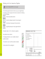
Selecting digitizing cycles
Call an overview of touch probe functions
Select a digitizing cycle via soft key
69
Digitizing
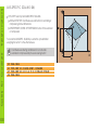
Digitizing Cycle RANGE (5)
Define the data transmission interface
Touch probe: Select Cycle 5 RANGE
PGM name for digitized data: Enter a name for the
NC program in which the digitized data should be stored.
TCH PROBE axis: Enter the axis of the touch probe
MIN. point range
MAX. point range
Clearance height: Height at which the stylus cannot collide
with the model surface: ZS
5
6
7
8
9
70
TCH
TCH
TCH
TCH
TCH
PROBE
PROBE
PROBE
PROBE
PROBE
5.0
5.1
5.2
5.3
5.4
RANGE
PGM NAME: DIGI1
Z X+0 Y+0 Z+0
X+100 Y+100 Z+20
HEIGHT: +100
Digitizing
Digitizing Cycle 6: MEANDER
A 3D surface can be scanned in a reciprocating line-by-line process
in Cycle 6 MEANDER.
Define the RANGE with Cycle 5
TOUCH PROBE: Select Cycle 6 MEANDER
Line direction: Coordinate axis in whose positive direction the
probe moves after touching the first contour point
Limit in normal lines direction (travel): Distance by which the
probe lifts off from the model surface after each deflection
Line spacing: Distance moved forward to start the next line
MAX. probe point interval
The line spacing and MAX. probe point interval cannot
exceed 5 mm.
Set a line direction that is as perpendicular as possible
to surface inclinations.
P: PP.INT = Probe point interval
L: L.SPAC = Line spacing
7 TCH PROBE 6.0 MEANDER
8 TCH PROBE 6.1 DIRECTN X
9 TCH PROBE 6.2 TRAVEL: 0.5 L.SPAC: 0.2 PP.INT:0.8
71
Digitizing
Digitizing Cycle 7: CONTOUR LINES
Cycle 7 CONTOUR LINES enables you to digitize a 3D surface level
by level.
Define Cycle 5 RANGE
TOUCH PROBE: Select Cycle 7 CONTOUR LINES
Time limit: If the touch probe has not orbited the model and
returned to the first touch point within this time, the TNC will
terminate the cycle. If you do not want a time limit, enter 0.
Starting point: Coordinates of the starting position
Axis and direction of approach: Coordinate axis and direction in
which the probe approaches the model
Starting probe axis and direction: Coordinate axis and direction in
which the probe begins scanning the model
Limit in normal lines direction (travel): Distance by which the
probe lifts off from the model surface after each deflection
Line spacing and direction: Distance moved upward to start the
next contour line
MAX. probe point interval
The line spacing and MAX. probe point interval
cannot exceed 5 mm.
10
11
12
13
72
TCH
TCH
TCH
TCH
PROBE
PROBE
PROBE
PROBE
7.0
7.1
7.2
7.3
CONTOUR LINES
TIME:200 X+50 Y+0
ORDER Y+/X+
TRAVEL 0.5 L.SPAC+1 PP.INT 0.2
P: PP.INT = Probe point interval
L: L.SPAC = Line spacing
See Test run and program run, graphics
Defining the Workpiece in the Graphic Window
In the open program, press the BLK FORM soft key
Spindle axis
MIN and MAX POINT
The following is a selection of frequently needed functions.
Interactive Programming Graphics
Select the PGM+GRAPHICS screen layout!
Graphics and Status Displays
Graphics and Status Displays
The TNC can generate a two-dimensional graphic of the contour while
you are programming it:
Automatic graphic generation during programming
Manually start graphic generation
Generate interactive graphics blockwise
73
Graphics and Status Displays
74
Test Graphics
Select the GRAPHICS or PGM+GRAPHICS screen layout!
In the test run mode the TNC can graphically simulate the machining
process. The following display types are available via soft key:
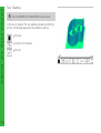
Plan view
Projection in three planes
3D view
Select a screen layout showing the status information that
you need.
In the program run modes a window in the lower part of the screen
shows information on
Tool position
Feed rate
Active M functions
Further status information is available via soft key for display in an
additional window:
Program information
Tool positions
Tool data
Coordinate transformations
Graphics and Status Displays
Status Displays
Tool measurement
75
ISO Programming
ISO-Programming
Programming Tool Movements with Cartesian
Coordinates
G00
G01
G02
G03
G05
G06
G07*
Linear motion in rapid traverse
Linear motion
Circular motion, clockwise
Circular motion, counterclockwise
Circular motion without directional data
Circular movement with tangential contour connection
Paraxial positioning block
Programming Tool Movements with Polar
Coordinates
G10
G11
G12
G13
G15
G16
76
Linear motion in rapid traverse
Linear motion
Circular motion, clockwise
Circular motion, counterclockwise
Circular motion without directional data
Circular movement with tangential contour
connection
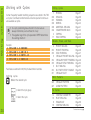
Drilling
G83
G200
G201
G202
G203
G204
G84
G85
Pecking
Drilling
Reaming
Boring
Universal boring
Counterbore back
Tapping
Rigid tapping (controlled spindle)
Pockets, Studs and Slots
G75
G76
G212
G213
G77
G78
G214
G215
G74
G210
G211
*) Effective blockwise
Cycles
Rectangular pocket milling, clockwise machining
direction
Rectangular pocket milling, counterclockwise
machining direction
Pocket milling
Stud milling
Circular pocket milling, clockwise machining
direction
Circular pocket milling, counterclockwise
machining direction
Circular pocket finishing
Circular stud finishing
Slot milling
Slot milling with reciprocating plunge
Circular slot
G 2 2 0 Circular point pattern
G 2 2 1 Linear point pattern
SL Cycles, Group I
G37
G56
G57
G58
G59
List of contour subprograms
Pilot drilling
Rough-out
Contour milling, clockwise
Contour milling, counterclockwise
Multipass
milling
G 2 3 0 Multipass milling
G 2 3 1 Ruled surface
Cycles for Coordinate Transformation
G53
G54
G28
G73
G72
Datum shift from datum tables
Entering datum shift directly
Mirror image
Rotating the coordinate system
Scaling factor: enlarging/reducing contours
ISO Programming
Point Patterns
Special Cycles
G04*
G36
G39
G79*
Dwell time
Oriented spindle stop
Designating a program as a cycle
Cycle call
Defining the Working Plane
G17
G18
G19
G20
*) Effective blockwise
X / Y working plane, tool axis Z
Z /X working plane, tool axis Y
Y/ Z working plane, tool axis X
Fourth axis is tool axis
77
ISO Programming
Chamfer,
G24*
G25*
G26*
G27*
Tool
G99*
Rounding,
Chamfer with side length R
Corner rounding with radius R
Tangential contour approach on an arc with radius R
Tangential contour departure on an arc with radius R
Definition
Tool definition in the program with length L and
radius R
Tool Radius Compensation
G40
G41
G42
G43
G44
No radius compensation
Radius compensation to the left of the contour
Radius compensation to the right of the contour
Paraxial radius compensation: the path is
lengthened
Paraxial radius compensation: the path is
shortened
Dimensional
G90
G91
78
Approach/Departure
Data
Absolute dimensions
Incremental (chain) dimensions
*) Effective blockwise
Unit of Measure (at Beginning of Program)
G70
G71
Inches
Millimeters
Blank Form Definition for Graphics
G30
G31
Setting the working plane, MIN point coordinates
Dimensional data (with G90, G91),
coordinates of the MAX point
G29
G38
G51*
G55*
G98*
Define last nominal position value as pole
Stopping the program run
Calling the next tool (only with central tool file)
Automatic measurement with the 3D touch probe
Setting a label number
Q Parameter Functions
D00
D01
D02
D03
D04
D05
D06
D07
D08
D13
D09
D10
D11
D12
D14
D15
D18
D19
*) Effective blockwise
Assign a value directly
Calculate and assign the sum of two values
Calculate and assign the difference of two values
Calculate and assign the product of two values
Calculate and assign the quotient of two values
Calculate and assign the root from a value
Calculate and assign the sine of an angle in
degrees
Calculate and assign the cosine of an angle in
degrees
Calculate and assign the square root of the sum
of two squares (Pythagorean theorem)
Find and assign an angle from the arc tangent of
two sides or from the sine and cosine of an angle
If equal, jump to the given label
If not equal, jump to the given label
If greater than, jump to the given label
If less than, jump to the given label
Output text to screen
Output text or parameter contents through the
data interface
Read system data
Transfer numerical values or Q parameters
to the PLC
ISO Programming
Other G functions
79
ISO Programming
Addresses
%
A
B
C
D
E
F
F
F
G
H
H
I
J
K
L
L
L
M
N
P
P
Q
80
Program beginning
Swivelling axis around X
Swivelling axis around Y
Rotary axis around Z
Define Q-parameter functions
Tolerance for rounding arc with M112
Feed rate in mm/min in positioning blocks
Dwell time in seconds with G04
Scaling factor with G72
G functions (see list of G functions)
Polar coordinate angle
Angle of rotation with G73
X coordinate of the circle center or pole
Y coordinate of the circle center or pole
Z coordinate of the circle center or pole
Label number with G98
Jump to a label number
Tool length with G99
Miscellaneous function
Block number
Cycle parameter for fixed cycles
Value or Q parameter with Q parameter
definitions
Variable Q parameter
R
R
R
R
R
S
S
T
T
T
U
V
W
X
Y
Z
*
Polar coordinate radius with G10/G11/G12/
G13/G15/G16/
Circle radius with G02/G03/G05
Corner radius with G25/G26/G27
Chamfer length with G24
Tool radius with G99
Spindle speed in rpm
Angle for spindle orientation with G36
Tool number with G99
Tool call
Call next tool with G51
Parallel axis to X
Parallel axis to Y
Parallel axis to Z
X axis
Y axis
Z axis
Character for end of block
M03
M04
M05
M06
M08
M09
M13
M14
M30
M89
M90
M91
M92
M93
M94
M97
M98
Stop program run/Stop spindle/Coolant off
Optional program stop
Stop program run/Stop spindle/Coolant off
Jump back to block 1/Clear status display
(depending on machine parameters)
Spindle on clockwise
Spindle on counterclockwise
Stop spindle
Tool change/Stop program run (depending on
machine parameters) Stop spindle
Coolant on
Coolant off
Spindle on clockwise/Coolant on
Spindle on counterclockwise/Coolant on
Same function as M02
Vacant miscellaneous function or
Cycle call, modally effective (depending on
machine parameters)
Constant contour speed at corners
(effective only in lag mode)
Within the positioning block: Coordinates are
referenced to the machine datum
Within the positioning block: The coordinates
are referenced to a position defined by the
machine tool builder
Reserved
Reduce rotary axis display to a value below 360°
Machine small contour steps
Suspend tool path compensation
M99
M101
M102
M103
M109
M110
M111
M112
M113
M120
M124
M126
M127
Cycle call, effective blockwise
Automatic tool change after tool lifetime expires
Reset M101
Reduce the feed rate during plunging to factor F
Constant contouring speed of tool cutting edge
on arcs (increasing and decreasing the feed rate)
Constant contouring speed of tool cutting edge
on arcs (only decreasing the feed rate)
Reset M109/M110
Insert a rounding arc between two lines,
with tolerance and limit angle
Reset M112
LOOK AHEAD: Calculate the radiuscompensated tool path ahead of time
Ignore points when calculating the rounding arc
with M112
Permit zero crossover on 360° rotary axes
Cancel M126
Functions
M00
M01
M02
Miscellaneous
Miscellaneous Functions M
81
HEIDENHAIN (G.B.) Limited
200 London Road, Burgess Hill
West Sussex RH15 9RD, Great Britain
{ (0 14 44) 24 77 11
| (0 14 44) 87 00 24
309 742-23 · SW19 · 5 · 10/2002 · Bi · Printed in Germany · Subject to change without notice
gb.pm6
88
14.10.2002, 10:43