1
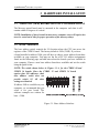
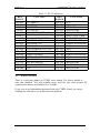
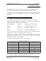
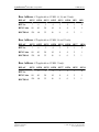
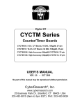
®
MetraByte Compatibles
CYREL Series
Relay Output Boards
CYREL 08: 8 Mechanical Relays, 50-pin
CYREL 16: 16 Mechanical Relays, 50-pin
CYREL 16M: 16 Mercury-wetted Board
CYREL 24: 24 Mechanical Relays, 50-pin
CYREL 32: 32 Mechanical Relays, 50-pin
USER’S MANUAL
VER. 6• AUG 2001
No part of this manual may be reproduced without permission
CyberResearch , Inc.
®
www.cyberresearch.com
25 Business Park Dr., Branford, CT 06405 USA
203-483-8815 (9am to 5pm EST) FAX: 203-483-9024
®
CyberResearch MetraByte Compatibles
CYREL Series
©Copyright 2001
All Rights Reserved.
August 2001
The information in this document is subject to change without prior notice
in order to improve reliability, design, and function and does not represent
a commitment on the part of CyberResearch, Inc.
In no event will CyberResearch, Inc. be liable for direct, indirect, special,
incidental, or consequential damages arising out of the use of or inability
to use the product or documentation, even if advised of the possibility of
such damages.
This document contains proprietary information protected by copyright.
All rights are reserved. No part of this manual may be reproduced by any
mechanical, electronic, or other means in any form without prior written
permission of CyberResearch, Inc.
Trademarks
“CyberResearch,” and “CyREL 08,” “CyREL 16,” “CyREL 16M,” “CyREL
24,” “CyREL 32,”are trademarks of CyberResearch, Inc. Other product
names mentioned herein are used for identification purposes only and may
be trademarks and/or registered trademarks of their respective companies.
• NOTICE •
CyberResearch, Inc. does not authorize any CyberResearch product for
use in life support systems, medical equipment, and/or medical devices
without the written approval of the President of CyberResearch, Inc. Life
support devices and systems are devices or systems which are intended
for surgical implantation into the body, or to support or sustain life and
whose failure to perform can be reasonably expected to result in injury.
Other medical equipment includes devices used for monitoring, data
acquisition, modification, or notification purposes in relation to life
support, life sustaining, or vital statistic recording. CyberResearch
products are not designed with the components required, are not subject
to the testing required, and are not submitted to the certification required
to ensure a level of reliability appropriate for the treatment and diagnosis of
humans.
CyberResearch, Inc.
25 Business Park Drive
Branford, CT USA
iii
P: (203) 483-8815; F: (203) 483-9024
www.cyberresearch.com
CYREL Series
®
CyberResearch MetraByte Compatibles
Intentionally Blank
iv
CYREL Series
®
CyberResearch MetraByte Compatibles
CYREL Series
Table of Contents
1 INTRODUCTION . . . . . . . . . . . . . . . . . . . . . . . . . . . . . . . . . . . . . . . . . . . . . . 1
2 INSTALLATION . . . . . . . . . . . . . . . . . . . . . . . . . . . . . . . . . . . . . . . . . . . . . . . 2
2.1 SOFTWARE INSTALLATION . . . . . . . . . . . . . . . . . . . . . . . . . . . . . . 2
3 HARDWARE INSTALLATION . . . . . . . . . . . . . . . . . . . . . . . . . . . . . . . . . 3
3.1 Mercury (/M) board special considerations . . . . . . . . . . . . . . . . . . . . . 3
3.2 BASE ADDRESS . . . . . . . . . . . . . . . . . . . . . . . . . . . . . . . . . . . . . . . . . . . 3
3.3 WAIT STATE . . . . . . . . . . . . . . . . . . . . . . . . . . . . . . . . . . . . . . . . . . . . . . 4
4 PROGRAMMING . . . . . . . . . . . . . . . . . . . . . . . . . . . . . . . . . . . . . . . . . . . . . . 5
4.1 DIRECT I/O REGISTER PROGRAMMING . . . . . . . . . . . . . . . . . . . 5
4.2 PROGRAMMING NOTES . . . . . . . . . . . . . . . . . . . . . . . . . . . . . . . . . . 6
4.3 DETAILED RELAY CONTROL I/O MAP . . . . . . . . . . . . . . . . . . . . 6
5 CONNECTING TO RELAYS . . . . . . . . . . . . . . . . . . . . . . . . . . . . . . . . . . . 8
5.1 I/O CONNECTOR DIAGRAMS . . . . . . . . . . . . . . . . . . . . . . . . . . . . . . 8
5.2 FORM C RELAYS (standard versions) . . . . . . . . . . . . . . . . . . . . . . . 10
5.3 FORM A RELAYS (/M versions) . . . . . . . . . . . . . . . . . . . . . . . . . . . . 10
6 SPECIFICATIONS . . . . . . . . . . . . . . . . . . . . . . . . . . . . . . . . . . . . . . . . . . . . 11
6.1.1 CYREL 08, 16, 24 and 32 (standard versions). . . . . . . . . . . . . . . . . . . . . 11
6.1.2 MERCURY WETTED (16M) VERSIONS . . . . . . . . . . . . . . . . . . . . . . . . 11
CyberResearch, Inc.
25 Business Park Drive
Branford, CT USA
v
P: (203) 483-8815; F: (203) 483-9024
www.cyberresearch.com
CYREL Series
®
CyberResearch MetraByte Compatibles
This page is blank.
vi
CYREL Series
®
CyberResearch MetraByte Compatibles
CYREL Series
1 INTRODUCTION
The CYREL 16 is a 16-channel relay interface board for ISA bus computers.
The board provides 16, Form-C (SPDT) relays. The CYREL 08 board is
identical to the CYREL 16 board except that only eight relays are installed.
The CYREL 32 is two CYREL 16s on a single board while the CYREL 24 is
a CYREL 32 with only 24 relays installed.
The CYREL 16M version is similar to the standard version, but uses form A mercurywetted relays (SPST). It offers quicker switching times, less contact bounce and lower
on-resistance than the standard models. The CYREL 16 family has been designed
for control applications where a few points of high voltage (or current) need
to be controlled.
WARNING!
High voltages will be present on the CYREL 16 family boards when high
voltage is connected to the CYREL 16 connector. Use extreme caution! Never
handle the CYREL 16 when signals are connected to the board through the
connector.
DO NOT REMOVE THE PROTECTIVE PLATES FROM THE CYREL 16!
The CYREL 16 family are digital I/O boards with relay-based signal
conditioning installed. Most accessory boards are intended to provide signal
conditioning or easy to access signal termination. In general, the CYREL 16
will not require additional signal conditioning.
WARNING
We STRONGLY recommend that under no circumstance should a screw terminal
board be used to connect high voltages to the CYREL 16 series board. The
CYREL 16 is intended to control high voltages. If you use a screw terminal
board you will expose yourself and others to those high voltage signals.
We recommend that you construct a safe cable to carry your signals directly from
your equipment to the CYREL 16 connector.
NOTE: The Mercury-wetted boards must be mounted in the computer such that they
will remain within 30 degrees of vertical.
Installation of these boards in most tower computer cases will require the tower be
rested on its side for proper operation of the mercury relays.
CyberResearch, Inc.
25 Business Park Drive
Branford, CT USA
1
P: (203) 483-8815; F: (203) 483-9024
www.cyberresearch.com
CYREL Series
®
CyberResearch MetraByte Compatibles
2 INSTALLATION
The installation and operation of all four CYREL series boards is very similar.
Throughout this manual we use CYREL as a generic designation for the
CYREL 08, CYREL 16, CYREL 24, and CYREL 32. When required,
due to the differences in the boards, the specific board name is used. The CYREL
boards are easy to use. These procedure will help you quickly and easily set up,
install and test your board. We assume you already know how to open the PC and
install expansion boards. If you are unfamiliar or uncomfortable with board
installation, please refer to your computer’s documentation.
We recommend you perform the software installation described in the following
sections prior to installing the board in your computer. The InstaCal operations
below will show you how to properly set the switches and jumpers on the board
prior to physically installing the board in your computer.
TM
2.1 SOFTWARE INSTALLATION
The board has a variety of switches and jumpers to set before installing the board in
your computer. The simplest way to configure your board is to use the InstaCalTM
program provided on the CD (or floppy disk) .
InstaCal will show you all available options, how to configure the various switches
and jumpers (as applicable) to match your application requirements. It will create a
configuration file that your application software (and the Universal Library) will
refer to so the software you use will automatically have access to the exact
configuration of the board.
2
CYREL Series
®
CyberResearch MetraByte Compatibles
CYREL Series
3 HARDWARE INSTALLATION
3.1 MERCURY (16M) BOARD SPECIAL CONSIDERATIONS
The Mercury-wetted board must be mounted in the computer such that it will
remain within 30 degrees of vertical.
NOTE: Installation of these boards in most tower computer cases will require the
tower be rested on its side for proper operation of the mercury relays.
3.2 BASE ADDRESS
The base address switch controls the I/O location where the CPU can access the
registers of the CYREL board. The factory default is 300h (768D). If you have
a board installed at address 300h, you will have to choose a new address from those
available on your computer. You may use the list of PC I/O address assignments
found on the following page and add notes about the boards you have installed in
your computer. Choose a new base address from those available and set the switch
using the guide below.
NOTE: The switch shown below in Figure 3-1 is for the CYREL 08 and
CYREL 16 boards. Since the CYREL 32 and CYREL 24 board
require four I/O addresses, their
base address switch does not
provide switch #2. All other
settings are identical.
If address 300h is available on your
computer, we recommend that you
select it for your board. The
software examples are written for
base = 300h.
Figure 3-1. Base Address Switches -
CyberResearch, Inc.
25 Business Park Drive
Branford, CT USA
3
P: (203) 483-8815; F: (203) 483-9024
www.cyberresearch.com
®
CyberResearch MetraByte Compatibles
CYREL Series
HEX
RANGE
000-00F
020-021
040-043
060-063
060-064
070-071
080-08F
0A0-0A1
0A0-0AF
0C0-0DF
0F0-0FF
1F0-1FF
200-20F
210-21F
238-23B
23C-23F
270-27F
2B0-2BF
Table 3-1. PC I/O Addresses
FUNCTION
HEX
RANGE
8237 DMA #1
2C0-2CF
8259 PIC #1
2D0-2DF
8253 TIMER
2E0-2E7
8255 PPI (XT)
2E8-2EF
8742 CONTROLLER (AT)
2F8-2FF
CMOS RAM & NMI MASK (AT)
300-30F
DMA PAGE REGISTERS
310-31F
8259 PIC #2 (AT)
320-32F
NMI MASK (XT)
378-37F
8237 #2 (AT)
380-38F
80287 NUMERIC CO-P (AT)
3A0-3AF
HARD DISK (AT)
3B0-3BB
GAME CONTROL
3BC-3BF
EXPANSION UNIT (XT)
3C0-3CF
BUS MOUSE
3D0-3DF
ALT BUS MOUSE
3E8-3EF
PARALLEL PRINTER
3F0-3F7
EGA
3F8-3FF
FUNCTION
EGA
EGA
GPIB (AT)
SERIAL PORT
SERIAL PORT
PROTOTYPE CARD
PROTOTYPE CARD
HARD DISK (XT)
PARALLEL PRINTER
SDLC
SDLC
MDA
PARALLEL PRINTER
EGA
CGA
SERIAL PORT
FLOPPY DISK
SERIAL PORT
3.3 WAIT STATE
There is a wait state jumper on CYREL series boards. The factory default is
wait state disabled. You will probably never need the wait state because PC
expansion slot busses are limited to 8 or 10 MHz.
If you were to get intermittent operation from your CYREL board, you can try
enabling the wait state to see if that solves the problem.
4
CYREL Series
®
CyberResearch MetraByte Compatibles
CYREL Series
4 PROGRAMMING
The CYREL boards are easy to program. From one to four eight-bit registers
are written to control relays or can be read to determine the state of relays.
In addition to direct I/O programming, the boards are fully supported by the
powerful Universal Library program as well as most third-party application
programs.
4.1 DIRECT I/O REGISTER PROGRAMMING
The CYREL family uses between one and four I/O addresses. Each address
controls eight relays. Relays are controlled by writing to these register(s). The
address map of the CYREL boards is shown below.
BASE ADDRESS
Relays 0-7
Read/Write (All CYREL boards
BASE + 1
Relays 8-15
Read/Write (CYREL 16, 24, 32)
BASE + 2
Relays 16-23
Read/Write (CYREL 24, 32)
BASE + 3
Relays 24-31
Read/Write (CYREL 32 only)
The registers are written to and read from as a single, 8-bit byte. Each bit controls an
output to a relay (write) or represents the state of a relay (read).
All registers are read left to right. The leftmost bit (the eighth bit) being the most
significant bit. Following this format, bit seven (OP7) of BASE + 0 corresponds to
relay number 7 and bit 0 to relay number 0.
To construct a control word, use Table 4.1 for bit weights.
BIT POSITION
0
1
2
3
4
5
6
7
Table 4-1. Bit Weights
DECIMAL VALUE
1
2
4
8
16
32
64
128
HEX VALUE
1
2
4
8
10
20
40
80
For example, to assemble the control byte that will turn on relays 0, 1, 3, 5, and 7,
we see in Table 4-2 that we need to write HEX AB or decimal 171.
CyberResearch, Inc.
25 Business Park Drive
Branford, CT USA
5
P: (203) 483-8815; F: (203) 483-9024
www.cyberresearch.com
®
CyberResearch MetraByte Compatibles
CYREL Series
RELAY
OP7
OP6
0P5
OP4
OP3
OP2
OP1
OP0
Table 4-2. Sample Coding to Turn ON Relays 0, 1, 3, 5, & 7
HEX
ON=1
WEIGHT
DECIMAL
WEIGHT
ON=1
80
1
80
128
1
128
40
0
0
64
0
0
20
1
20
32
1
32
10
0
0
16
0
0
8
1
8
8
1
8
4
0
0
4
0
0
2
1
2
2
1
2
1
1
1
1
1
1
Totals
AB
171
4.2 PROGRAMMING NOTES
WRITE = CONTROL: Write a byte to the register to control the relays. A one in the
relay bit position turns the relay on.
READ = STATUS: Read the status of the relay control register. A one in the relay
bit position indicates the relay is on.
ON & OFF for FORM C RELAYS:
ON means that FORM C relay common terminal is in contact with the Normally
Open contact.
OFF means that FORM C relay common terminal is in contact with the normally
closed contact.
4.3 DETAILED RELAY CONTROL I/O MAP
The following section provides a detailed description of the register map and relay
control registers.
Base Address +0 (applicable to all CYREL series boards).
RELAY
OP7
OP6
OP5
OP4
OP3
OP2
OP1
OP0
BIT No.
7
6
5
4
3
2
1
0
HEX Value
80
40
20
10
8
4
2
1
DECIMAL
128
64
32
16
8
4
2
1
6
CYREL Series
®
CyberResearch MetraByte Compatibles
CYREL Series
Base Address + 1 (applicable to CYREL 16, 24, and 32 only).
OP14
OP13
OP11
OP10
OP9
4
3
2
1
0
20
10
8
4
2
1
32
16
8
4
2
1
RELAY
OP15
BIT No.
7
6
5
HEX Value
80
40
DECIMAL
128
64
OP12
OP8
Base Address + 2 (applicable to CYREL 24, and 32 only).
OP22
OP21
OP19
OP18
OP17
4
3
2
1
0
20
10
8
4
2
1
32
16
8
4
2
1
OP27
OP26
OP25
RELAY
OP23
BIT No.
7
6
5
HEX Value
80
40
DECIMAL
128
64
OP20
OP16
Base Address + 3 (applicable to CYREL 32 only).
OP30
OP29
OP28
OP24
RELAY
OP31
BIT No.
7
6
5
4
3
2
1
0
HEX Value
80
40
20
10
8
4
2
1
DECIMAL
128
64
32
16
8
4
2
1
CyberResearch, Inc.
25 Business Park Drive
Branford, CT USA
7
P: (203) 483-8815; F: (203) 483-9024
www.cyberresearch.com
®
CyberResearch MetraByte Compatibles
CYREL Series
5 CONNECTING TO RELAYS
5.1 I/O CONNECTOR DIAGRAMS
The CYREL 08 and CYREL 16 boards use a single 50-pin connector for signal
interfacing. The CYREL 24 and CYREL 32 use two, 50-pin connectors.
The pin-outs of the connectors are shown in Figures 5-1 through 5-4.
Figure 5-1. CYREL 08 & 16
Connector
Figure 5-2. CYREL 16M Connector
Note that the form A relays used on the 16M version have NO and COM
connections only (Figure 5-2).
WARNING!
High voltages will be present on the CYREL boards when you have connected
high voltage inputs or outputs to the CYREL connector. Use extreme caution!
Never handle the CYREL board when high voltage signals are connected to it.
DO NOT REMOVE THE PROTECTIVE PLATES FROM THE BOARD.
8
CYREL Series
®
CyberResearch MetraByte Compatibles
CYREL Series
Figure 5-3. CYREL 24 & 32 Connector
The CYREL 24 & 32 connector (Figure 5-3) is the center of the board.
The connector for relays 0 through 15 is closest to the computer back-plate.
NOTE: Pins for relays 24 through 31 are open on the CYREL 24 version.
WARNING!
High voltages will be present on the CYREL boards when you have connected
high voltage inputs or outputs to the CYREL connector. Use extreme caution!
Never handle the CYREL board when HV signals are connected to the board.
DO NOT REMOVE THE PROTECTIVE PLATES FROM THE BOARD.
CyberResearch, Inc.
25 Business Park Drive
Branford, CT USA
9
P: (203) 483-8815; F: (203) 483-9024
www.cyberresearch.com
CYREL Series
®
CyberResearch MetraByte Compatibles
5.2 FORM C RELAYS (STANDARD VERSIONS)
Figure 5-4 is the schematic for a Form-C relay as used on the standard
CYREL 08, 16, 24 and 32 boards.
The Form-C relay has a COMMON (COM), a normally open (NO), and a normally
closed (NC) contact. When a 0 is written to an output (OPn), the common and NC
are in contact. When a “1” is written to an output (OPn), the common and NO are in
contact.
Figure 5-4. Form C Relay
5.3 FORM A RELAYS (/M VERSIONS)
Figure 5-5 is the schematic for a Form-A relay as used on mercury-wetted (16M)
model.
A Form-A relay has COMMON (COM) and normally open (NO) connections.
When a “0” is written to the output, the common and NO are disconnected. When a
“1” is written to the output (OPn), the common and NO are in contact.
Figure 5-5. Form A Relay
10
CYREL Series
®
CyberResearch MetraByte Compatibles
CYREL Series
6 SPECIFICATIONS
6.1.1 CYREL 08, 16, 24 and 32 (standard versions)
POWER CONSUMPTION
+5V supply
510 mA typical plus 22 mA per active (on) relay
GENERAL SPECIFICATIONS
Number
8, 16, 24, or 32
Contact arrangement
Form C (SPDT)
Contact rating
3A @ 120VAC or 28VDC resistive
Contact type
Gold-overlayed silver
Contact resistance
100 milliohms max.
Operate time
20 milliseconds
Release time
10 milliseconds max.
Life expectancy
10 million mechanical operations minimum
ENVIRONMENTAL
Vibration
Shock
Dielectric isolation
Life expectancy
10 to 55 Hz (Dual amplitude 1.5mm)
10g (11 milliseconds)
500V (1 minute)
1 Million Operations Electrical
100,000 Operations @ Full Load
6.1.2 MERCURY WETTED (16M) VERSIONS
POWER CONSUMPTION
CYREL
510 mA + (22 mA per activated relay max)
GENERAL SPECIFICATIONS
Number
Contact arrangement
Contact rating
Contact type
Contact resistance
Operate time
Release time
Dielectric isolation
Life expectancy
8 /16
Form A (SPST)
50 watts @ 1 Amp or 500VDC resistive
Mercury-wetted
50 milliohms max.
2 milliseconds
2 milliseconds max.
500V (1 minute)
107 Operations (Full Load)
CyberResearch, Inc.
25 Business Park Drive
Branford, CT USA
11
P: (203) 483-8815; F: (203) 483-9024
www.cyberresearch.com
CYREL Series
®
CyberResearch MetraByte Compatibles
ENVIRONMENTAL
Operating temperature
Storage temperature
Humidity
Weight
0 to 70 °C
-40 to 100 °C
0 to 90% non-condensing
8 oz.
NOTE: The Mercury-wetted boards must be mounted in the computer such that they
will remain within 30 degrees of vertical.
Installation of these boards in most tower computer cases will require the tower be
rested on its side for proper operation of the mercury relays.
12
CYREL Series
®
CyberResearch MetraByte Compatibles
CYREL Series
EC Declaration of Conformity
We declare under sole responsibility that the
product:
CYREL ##
8, 16, 24 or 32 channel relay board
Part Number
Description
to which this declaration relates, meets the essential requirements, is in conformity
with, and CE marking has been applied according to the relevant EC Directives
listed below using the relevant section of the following EC standards and other
normative documents:
EU EMC Directive 89/336/EEC:
electromagnetic compatibility.
Essential
requirements
relating
to
EU 55022 Class B: Limits and methods of measurements of radio interference
characteristics of information technology equipment.
EN 50082-1: EC generic immunity requirements.
IEC 801-2: Electrostatic discharge requirements for industrial process measurement
and control equipment.
IEC 801-3: Radiated electromagnetic field requirements for industrial process
measurements and control equipment.
IEC 801-4: Electrically fast transients for industrial process measurement and
control equipment.
CyberResearch, Inc.
25 Business Park Drive
Branford, CT USA
13
P: (203) 483-8815; F: (203) 483-9024
www.cyberresearch.com
CYREL Series
®
CyberResearch MetraByte Compatibles
Intentionally Blank
14
CYREL Series
®
CyberResearch MetraByte Compatibles
CYREL Series
Product Service
Diagnosis and Debug
CyberResearch, Inc. maintains technical support lines staffed by experienced
Applications Engineers and Technicians. There is no charge to call and we will
return your call promptly if it is received while our lines are busy. Most problems
encountered with data acquisition products can be solved over the phone. Signal
connections and programming are the two most common sources of difficulty.
CyberResearch support personnel can help you solve these problems, especially
if you are prepared for the call.
To ensure your call’s overall success and expediency:
1)
2)
3)
4)
5)
6)
Have the phone close to the PC so you can conveniently and quickly take
action that the Applications Engineer might suggest.
Be prepared to open your PC, remove boards, report back-switch or
jumper settings, and possibly change settings before reinstalling the
modules.
Have a volt meter handy to take measurements of the signals you are
trying to measure as well as the signals on the board, module, or power
supply.
Isolate problem areas that are not working as you expected.
Have the source code to the program you are having trouble with available
so that preceding and prerequisite modes can be referenced and
discussed.
Have the manual at hand. Also have the product’s utility disks and any
other relevant disks nearby so programs and version numbers can be
checked.
Preparation will facilitate the diagnosis procedure, save you time, and avoid
repeated calls. Here are a few preliminary actions you can take before you call
which may solve some of the more common problems:
1)
2)
3)
4)
Check the PC-bus power and any power supply signals.
Check the voltage level of the signal between SIGNAL HIGH and SIGNAL
LOW, or SIGNAL+ and SIGNAL– . It CANNOT exceed the full scale range
of the board.
Check the other boards in your PC or modules on the network for address
and interrupt conflicts.
Refer to the example programs as a baseline for comparing code.
CyberResearch, Inc.
25 Business Park Drive
Branford, CT USA
15
P: (203) 483-8815; F: (203) 483-9024
www.cyberresearch.com
CYREL Series
®
CyberResearch MetraByte Compatibles
Intentionally Blank
16
CYREL Series
®
CyberResearch MetraByte Compatibles
CYREL Series
Warranty Notice
CyberResearch, Inc. warrants that this equipment as furnished will be free from
defects in material and workmanship for a period of one year from the confirmed
date of purchase by the original buyer and that upon written notice of any such
defect, CyberResearch, Inc. will, at its option, repair or replace the defective item
under the terms of this warranty, subject to the provisions and specific exclusions
listed herein.
This warranty shall not apply to equipment that has been previously repaired or
altered outside our plant in any way which may, in the judgment of the manufacturer,
affect its reliability. Nor will it apply if the equipment has been used in a manner
exceeding or inconsistent with its specifications or if the serial number has been
removed.
CyberResearch, Inc. does not assume any liability for consequential damages as a
result from our products uses, and in any event our liability shall not exceed the
original selling price of the equipment.
The equipment warranty shall constitute the sole and exclusive remedy of any Buyer
of Seller equipment and the sole and exclusive liability of the Seller, its successors
or assigns, in connection with equipment purchased and in lieu of all other
warranties expressed implied or statutory, including, but not limited to, any implied
warranty of merchant ability or fitness and all other obligations or liabilities of seller,
its successors or assigns.
The equipment must be returned postage prepaid. Package it securely and insure it.
You will be charged for parts and labor if the warranty period has expired.
Returns and RMAs
If a CyberResearch product has been diagnosed as being non-functional, is visibly
damaged, or must be returned for any other reason, please call for an assigned
RMA number. The RMA number is a key piece of information that lets us track and
process returned merchandise with the fastest possible turnaround time.
PLEASE CALL FOR AN RMA NUMBER!
Packages returned without an RMA number will be refused!
In most cases, a returned package will be refused at the receiving dock if its
contents are not known. The RMA number allows us to reference the history of
returned products and determine if they are meeting your application’s requirements.
When you call customer service for your RMA number, you will be asked to provide
information about the product you are returning, your address, and a contact person
at your organization.
Please make sure that the RMA number is prominently
displayed on the outside of the box.
• Thank You •
CyberResearch, Inc.
25 Business Park Drive
Branford, CT USA
17
P: (203) 483-8815; F: (203) 483-9024
www.cyberresearch.com
CYREL Series
®
CyberResearch MetraByte Compatibles
Intentionally Blank
18
CYREL Series
CyberResearch, Inc.
25 Business Park Drive
Branford, CT 06405 USA
P: (203) 483-8815; F: (203) 483-9024
www.cyberresearch.com