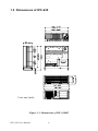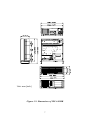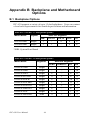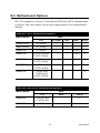
1
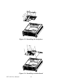
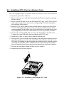
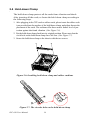
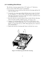
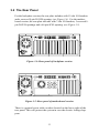
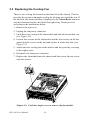
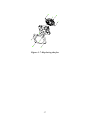
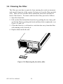
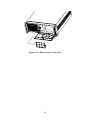
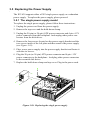
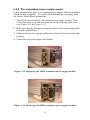
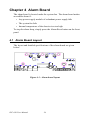
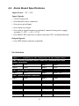
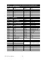
IPC-630 Series
4U-High Rackmount
Industrial Chassis with
Alarm Notification
User Manual
Copyright notice
This document is copyrighted, 2006, by Advantech Co., Ltd. All rights
are reserved. Advantech Co., Ltd. reserves the right to make improvements to the products described in this manual at any time without notice.
No part of this manual may be reproduced, copied, translated or transmitted in any form or by any means without the prior written permission of
Advantech Co., Ltd. Information provided in this manual is intended to
be accurate and reliable. However, Advantech Co., Ltd. assumes no
responsibility for its use, nor for any infringements upon the rights of
third parties which may result from its use.
Acknowledgements
Intel®, Pentium® 4, and Celeron® are trademarks of Intel Corporation.
IPC-630, PCE-7B13-64A1, PCE-5B12-64A1, PCA-6115, PCA-6114,
PCA-6114P4, PCA-6114P7, PCA-6114P10, PCA-6114P12, and PCA6114P12X, PCA-6113P4R, PCA-6113P7X, PCA-6113DP4, AIMB-740,
AIMB-742, AIMB-744, AIMB-750, AIMB-760, AIMB-762, AIMB-554,
and AIMB-560 are trademarks of Advantech Co., Ltd.
All other product names or trademarks are the properties of their respective owners.
Note:
The information in this document is provided for
reference only. Advantech does not assume
any liability arising out of the application or use
of the information or products described herein.
This manual is subject to change without notice.
Part No. 2002063000
IPC-630 User Manual
1st Edition
June 2006
Printed in China
ii
A Message to the Customer
Advantech customer services
Each and every Advantech product is built to the most exacting specifications to ensure reliable performance in the harsh and demanding conditions typical of industrial environments. Whether your new Advantech
equipment is destined for the laboratory or the factory floor, you can be
assured that your product will provide the reliability and ease of operation
for which the name Advantech has come to be known. Your satisfaction
is our primary concern. Here is a guide to Advantech's customer services.
To ensure you get the full benefit of our services, please follow the
instructions below carefully.
Technical support
We want you to get the maximum performance from your products. So, if
you run into technical difficulties, we are here to help. For the most frequently asked questions, you can easily find answers in your product documentation. These answers are normally a lot more detailed than the ones
we can give over the phone.
Please consult this manual first. If you still cannot find the gather all the
information or answer questions that apply to your problem, please call
your dealer. Please make sure you have the product close at hand. Our
dealers are well trained and ready to give you the support you need to get
the most from your Advantech products. In fact, most problems reported
are minor and are easily solved over the phone.
In addition, free technical support is available from Advantech engineers
every business day. We are always ready to give advice on application
requirements or specific information on the installation and operation of
any of our products.
On-line Technical Support
For technical support and service, please visit our support website at:
http://www.advantech.com/support
iii
Product warranty
Advantech warrants to you, the original purchaser, that each of its products will be free from defects in materials and workmanship for two years
from the date of purchase.
This warranty does not apply to any products which have been repaired or
altered by persons other than repair personnel authorized by Advantech,
or which have been subject to misuse, abuse, accident or improper installation. Advantech assumes no liability under the terms of this warranty as
a consequence of such events.
Because of Advantech's high quality-control standards and rigorous testing, most of our customers never need to use our repair service. If an
Advantech product is defective, it will be repaired or replaced at no
charge during the warranty period. For out-of-warranty repairs, you will
be billed according to the cost of replacement materials, service time and
freight. Please consult your dealer for more details.
If you think you have a defective product, follow these steps:
1. Collect all the information about the problem encountered. (For example, the model no. of the product, the CPU speed, Advantech products
used, other hardware and software used, etc.) Note anything abnormal
and list any on-screen messages you get when the problem occurs.
2. Call your dealer and describe the problem. Please have your manual,
product, and any helpful information readily available.
3. If your product is diagnosed as defective, obtain an RMA (return
material authorization) number from your dealer. This allows us to
process your return more quickly.
4. Carefully pack the defective product, a fully-completed Repair and
Replacement Order Card and a photocopy proof of purchase date
(such as your sales receipt) in a shippable container. A product
returned without proof of the purchase date is not eligible for warranty
service.
5. Write the RMA number visibly on the outside of the package and ship
it prepaid to your dealer.
IPC-630 User Manual
iv
Initial Inspection
Before you installing your motherboard, please make sure that the following materials have been shipped:
•
IPC-630 Chassis
•
User Manual
•
Warranty Card
•
Accessory box with a package of screws (for fastening the disk
drives), four rubber pads, 15 pcs rubber cushions (backplane version)
or 7 pcs (motherboard version), one pc of EMI spring shielding (for
the backplane version only), a pair of keys, and a pair of ears.
If any of these items are missing or damaged, contact your distributor or
sales representative immediately. We have carefully inspected the IPC630 mechanically and electrically before shipment. It should be free of
marks and scratches and in perfect working order upon receipt. As you
unpack the IPC-630, check it for signs of shipping damage. (For example,
damaged box, scratches, dents, etc.) If it is damaged or it fails to meet the
specifications, notify our service department or your local sales representative immediately. Also notify the carrier. Retain the shipping carton and
packing material for inspection by the carrier. After inspection, we will
make arrangements to repair or replace the unit.
v
Contents
Chapter
1 General Information ........................................2
1.1
1.2
1.3
Introduction ....................................................................... 2
Specifications .................................................................... 3
Power Supply Options................................................... 4
1.4
Environmental Specifications .......................................
Table 1.1: Power Supply Options ................................... 4
5
Table 1.2: Environmental Specifications........................ 5
1.5
Dimensions of IPC-630..................................................... 6
Figure 1.1: Dimensions of IPC-630BP ........................... 6
Figure 1.2: Dimensions of IPC-630MB.......................... 7
1.6
1.7
Chapter
Safety Precautions
....................................... 8
FCC ................................................................................... 9
2 System Setup...................................................12
2.1
Removing the Chassis Cover .......................................... 12
2.2
Installing the Backplane or Motherboard........................ 13
Figure 2.1: Removing the chassis cover ....................... 12
Figure 2.2: Yellow label for indicating screw locations13
Figure 2.3: Installing the backplane.............................. 14
Figure 2.4: Installing a motherboard............................. 14
2.3
Installing CPU Card or Add-on Card.............................. 15
2.4
Hold-down Clamp ........................................................... 16
Figure 2.5: Installing a full-length CPU card ............... 15
Figure 2.6: Installing hold-down clamp and rubber cushions .. 16
Figure 2.7: The circular hole on the hold-down clamp. 16
2.5
Installing Disk Drives...................................................... 17
Figure 2.8: Removing the disk drive housing............... 17
Figure 2.9: Removing the 3.5" FDD brackets and front covers 18
Figure 2.10: Installing the disk drives .......................... 18
2.6
Attaching the Ears ........................................................... 19
Figure 2.11: Attaching the ears..................................... 19
Chapter
3 Operation ........................................................22
3.1
The Front Panel of IPC-630 ............................................ 22
3.1.1
3.1.2
3.2
Figure 3.1: Closed Front panel of IPC-630................... 22
Figure 3.2: Open Front panel of IPC-630 ..................... 22
Switches, Buttons and Front I/O Interfaces ................. 23
Figure 3.3: Switch, buttons and front I/O interfaces..... 23
LED indicators............................................................. 24
Table 3.1: LED indicator functions .............................. 24
The Rear Panel ................................................................ 25
Figure 3.4: Rear panel of backplane version ................ 25
1
Figure 3.5: Rear panel of motherboard version ............ 25
3.3
Replacing the Cooling Fan.............................................. 26
Figure 3.6: Undo the single screw to remove the fan module.. 26
Figure 3.7: Replacing the fan........................................ 27
3.4
Cleaning the Filter........................................................... 28
Figure 3.8: Removing the front door filter ................... 28
Figure 3.9: Removing the fan filter .............................. 29
3.5
Replacing the Power Supply ........................................... 30
3.5.1
3.5.2
Chapter
The single power supply model ................................... 30
Figure 3.10: Replacing the single power supply........... 30
The redundant power supply model............................. 31
Figure 3.11: Replacing the 300W redundant power supply module.. 31
Figure 3.12: Replacing the 400W redundant power supply module.. 31
Figure 3.13: Power cord plugs orientation on the socket .... 32
4 Alarm Board ...................................................34
4.1
Alarm Board Layout....................................................... 34
4.2
Alarm Board Specifications ........................................... 35
4.3
Jumper Settings
Figure 4.1: Alarm board layout..................................... 34
Table 4.1: Summary of the connectors on the alarm board.. 35
......................................................... 37
Table 4.2: J2, PIC Clear jumper ................................... 37
Table 4.3: J3, Thermal Sensor jumper.......................... 37
Table 4.4: J4, Fan Option jumper ................................. 37
4.4
Thermal Sensor ............................................................... 38
Figure 4.2: Thermal sensor location ............................. 38
Appendix A
Exploded Diagram ........................................40
Figure A.1: Exploded diagram of the Backplane version.... 40
Figure A.2: Exploded diagram of the Motherboard version 41
Appendix B Backplane and Motherboard Options..........44
B.1
Backplane Options .......................................................... 44
Table B.1: PICMG 1.3 Backplane options ................... 44
Table B.2: PICMG 1.0 Backplane options ................... 44
B.2
Motherboard Options ...................................................... 45
Table B.3: ATX Motherboard Options......................... 45
Table B.4: MicroATX Motherboard Options ............... 45
Appendix C
Safety Instructions ........................................48
C.1
C.2
English............................................................................. 48
German - Wichtige Sicherheishinweise .......................... 49
IPC-630 User Manual
2
CHAPTER
1
General Information
1
Chapter 1 General Information
1.1 Introduction
The IPC-630 is a 4U-high 15-slot rackmount industrial computer chassis
designed for mission-critical applications. It supports either backplane or
motherboard.
Audible alarm detection and notification with visible LED indicators
The IPC-630 comes with an audible alarm module. It automatically
detects the system operating conditions, such as power, fan, temperature,
and HDD, and displays the system status on the front visible LED indicators. Once any failure happens, the alarm module will make a beep to
warn users to take necessary actions. This feature reduces the system
downtime. Unique alarm detection and notification to reduce system
down time.
Outstanding ID and mechanical design
Unlike the classical industrial computer, IPC-630 has an innovative
appearance for an industrial computer chassis. The flexible mechanical
design supports a single PS/2 or redundant power supply using a power
bracket replacement. The shockproof disk drive housing and the rubber
cushions protect the system against harsh industrial environments or
unexpected shocks. The lockable front door prevents unauthorized access
to data storage. All these outstanding features make the IPC-630 an ideal
solution for the price, performance and total cost of ownership.
IPC-630 User Manual
2
1.2 Specifications
General
• Construction: Heavy-duty steel
• Disk drive capacity: three 5.25" disk drives (CD-ROM or CD-R/W
drive or DVD-ROM drive), one 3.5" FDD, and one internal 3.5" disk
drive
• Front I/O interfaces: Dual USB port and a reserved 9-pin D-SUB
opening
• Rear I/O interfaces: a reserved 9-pin D-SUB opening for the backplane version; five reserved 9-pin D-SUB and a 68-pin SCSI openings
for the motherboard version
• LED Indicators: Bi-color LEDs (green/red) for Power, Temperature,
and Fan status; single-color LEDs (green) for HDD activity
• Switch and Buttons: System Reset button, Alarm Reset button, and
Power switch
• Cooling fan: One 114 CFM (12 cm x 12 cm) cooling fan with air filter
near the front left of the chassis.
• Air Filters: Two easily maintained reusable filters near the front of the
system fan and behind the front door
• Gross Weight: 18 kg (39.6 lb)
• Dimensions (WxHxD):
Backplane version: 482 mm x 177 mm x 447 mm (19" x 7" x 17.6");
Motherboard version: 482 mm x 177 mm x 497 mm (19" x 7" x 19.6")
3
1.3 Power Supply Options
Table 1.1: Power Supply Options
Model Name
PS-300ATX-ZB
RPS-300ATX-Z
Watt
300 W max. (ATX, PFC)
300 W max. (ATX, PFC)
(1+1 redundant)
Input rating
100 ~ 240 Vac (Full range)
100 ~ 240 Vac (Full range)
Output voltage
+5 V @ 30 A, +3.3 V @ 28 A,
+12 V @ 15 A, -5 V @ 0.3 A,
-12 V @ 0.8 A, +5 Vsb @ 2 A
+5 V @ 25 A, +3.3 V @ 18 A,
+12 V @ 16 A, -5 V @ 0.5 A,
-12 V @ 0.5 A, +5 Vsb @ 2 A
Minimum load
+5 V @ 0.1 A, +3.3 V @ 0.3 A
+5 V @ 3 A, +3.3 V @ 1 A,
+12 V @ 2 A, +5 Vsb @
0.1 A
MTBF
100,000 hours @ 25° C
100,000 hours @ 25° C
Safety
UL/TUV/CB/CCC
UL/TUV/CB/CCC
Model Name
PS-400ATX-ZB
RPS-400ATX-Z
Watt
400 W max. (ATX, PFC)
400 W max. (ATX, PFC)
(1+1 redundant)
Input rating
100 ~ 240 Vac
(Full range)
100 ~ 240 Vac
(Full range)
Output voltage
+5 V @ 35 A, +3.3 V @ 25 A,
+12 V @ 30 A, -5 V @ 0.8 A,
-12 V @ 1 A, +5 Vsb @ 2 A
+5 V @ 35 A, +3.3 V @ 25 A,
+12 V @ 28 A, -5 V @ 0.5 A,
-12 V @ 1.2 A, +5 Vsb @ 2 A
Minimum load
+5 V @ 3 A, +3.3 V @ 1 A, +12
V @ 1 A, +5 Vsb @ 0.1 A
+5 V @ 3 A, +3.3 V @ 1 A,
+12 V @ 2 A, +5 Vsb @ 0.1 A
MTBF
91,000 hours @ 25° C
100,000 hours @ 25° C
Safety
UL/TUV/CB/CCC
UL/TUV/CB/CCC
IPC-630 User Manual
4
1.4 Environmental Specifications
Table 1.2: Environmental Specifications
Environment
Operating
Non-operating
Temperature
0 to 40°C (32 to 104°F)
-20 to 60°C (-4 to 140°F)
Humidity
10 to 85% @ 40°C, noncondensing
10 to 95% @ 40°C, noncondensing
Vibration
1G rms
2G
Shock
10G (with 11 ms duration,
half sine wave)
30G
Altitude
0 to 3,048 m (0 ~ 10,000 ft)
Safety
CE compliant, UL/cUL approved
5
1.5 Dimensions of IPC-630
Unit: mm [inch]
Figure 1.1: Dimensions of IPC-630BP
IPC-630 User Manual
6
Unit: mm [inch]
Figure 1.2: Dimensions of IPC-630MB
7
1.6 Safety Precautions
Warning!
Always completely disconnect the power
cord from your chassis whenever you work
with the hardware. Do not make connections while the power is on. Sensitive electronic components can be damaged by
sudden power surges. Only experienced
electronics personnel should open the PC
chassis.
Caution!
Always ground yourself to remove any
static charge before touching the motherboard, backplane, or add-on cards. Modern
electronic devices are very sensitive to
static electric charges. As a safety precaution, use a grounding wrist strap at all times.
Place all electronic components on a staticdissipative surface or in a static-shielded
bag when they are not in the chassis.
IPC-630 User Manual
8
1.7 FCC
This device complies with the requirements in part 15 of the FCC rules:
Operation is subject to the following two conditions:
1.
This device may not cause harmful interference, and
2.
This device must accept any interference received, including interference that may cause undesired operation
This equipment has been tested and found to comply with the limits for a
Class A digital device, pursuant to Part 15 of the FCC Rules. These limits
are designed to provide reasonable protection against harmful interference when the equipment is operated in a commercial environment. This
equipment generates, uses, and can radiate radio frequency energy and, if
not installed and used in accordance with the instruction manual, may
cause harmful interference to radio communications. Operation of this
device in a residential area is likely to cause harmful interference in
which case the user will be required to correct the interference at his/her
own expense. The user is advised that any equipment changes or modifications not expressly approved by the party responsible for compliance
would void the compliance to FCC regulations and therefore, the user's
authority to operate the equipment.
9
CHAPTER
System Setup
11
2
Chapter 2 System Setup
The following procedures guide users to install the backplane, motherboard, add-on cards, and disk drives into the IPC-630 chassis. Please also
refer to Appendix A, Exploded Diagram, for all the parts of IPC-630.
Note:
Use caution when installing or operating the
components with the chassis open. Be sure
to turn off the power, unplug the power cord
and ground yourself by touching the metal
chassis before you handle any components
inside the machine.
2.1 Removing the Chassis Cover
Please refer to Figure 2.1 and proceed as below.
1. Detach the four screws on the left and right of the chassis.
2. Remove the top cover rearwards gently.
Figure 2.1: Removing the chassis cover
IPC-630 User Manual
12
2.2 Installing the Backplane or Motherboard
The IPC-630 supports either up to 15-slot backplane or ATX/microATX
motherboard. To install the backplane or motherboard, please proceed as
follows:
1. Dismantle the hold-down clamp by undoing the two screws on its both ends.
2. There is a yellow warning label located inside of the chassis bottom. (see Figure 2.2) It shows the screw locations for attaching the various backplanes or
motherboards. Be sure to follow the instruction and fasten the backplane or
motherboard onto the chassis with the correct screw locations.
3. For the backplane, after fastening it, please attach the supplied spring shielding
with the screws provided.
4. For the motherboard, attach the motherboard I/O shielding onto the rear plate
first. Then fasten the motherboard onto the chassis.
5. Connect the 20-pin (or 24-pin) ATX power connector and the 4-pin +12V
power connector from the power supply to the backplane or the motherboard.
6. Connect the 9-pin USB cable from the chassis to the motherboard.
7. Replace the hold-down clamp and fasten them to the chassis.
MB \ Nut #
1 2 3 4 5 6 7 8 9 10 11 12 13 14 15 16 17 18 19 20 21 22 23 24 25 26 27 28 29 X A M
Backplane
PCA-6113P4R
PCA-6114P7 * * * * *
PCA-6114P12
* * * * * * * *
* * * *
PCA-6114P4
PCA-6114P10 * * * * *
PCA-6113DP4
* * * * * * * *
* *
*
* * * * *
* * * * * * * *
*
*
*
* *
*
* *
*
PCA-6114-B
PCA-6113P7X * * * * *
PCA-6115
* *
* * * * *
* *
*
* * * * * *
PCA-6114P12X * * * * *
* * *
*
*
*
*
PCE-7B13-64
* * * * *
PCE-5B12-64
*
* *
*
*
* *
*
AIMB-740
AIMB-741
AIMB-742
* * *
*
*
AIMB-744
AIMB-750
AIMB-760
* * *
*
AIMB-762
* * *
*
AIMB-554
AIMB-560
* *
*
*
*
*
*
*
*
*
*
*
*
*
*
*
*
* *
*
Be careful to screw the Copper Stub no more than 10 kgf • cm.
Figure 2.2: Yellow label for indicating screw locations
13
*
Figure 2.3: Installing the backplane
Figure 2.4: Installing a motherboard
IPC-630 User Manual
14
2.3 Installing CPU Card or Add-on Card
IPC-630 supports up to 15 add-on cards. To install a CPU card or add-on
card, please proceed as follows:
1. Remove the top cover, and then dismantle the hold-down clamp by removing
the two screws.
2. Select a vacant PICMG slot for the full-length CPU card, or a PCI/ISA slot for
other add-on cards. Then, remove the corresponding I/O bracket attached to
the rear plate of the chassis.
3. Insert the CPU card or add-on card vertically into the proper slot (See Figure
2.5). For full-length cards, please make sure that the card bracket has been
inserted properly and the other edge of the card has been inserted into the plastic guiding fillister. Fasten the card with the screw on top of the I/O bracket.
4. Connect the +5Vsb and PS_ON wires from the backplane to the CPU card.
Connect the 9-pin USB cable from the chassis to the CPU card.
5. Repeat Step 2 and 3 if there is more than one add-on card.
6. There are two rows of notches on both sides of the hold-down clamp for inserting rubber cushions into. One side is for PCI cards, while the other side is for
ISA cards. Depending on the card height, the cushions can be inserted upward
or downward. After the rubber cushions have been inserted into the notches,
they will stabilize the add-on cards to protect them from shock and vibration.
7. Put back the hold-down clamp and then screw it in place.
8. Replace the top cover and fasten it.
Figure 2.5: Installing a full-length CPU card
15
2.4 Hold-down Clamp
The hold-down clamp protects all the cards from vibration and shock.
After inserting all the cards, re-fasten the hold-down clamp according to
the following steps.
1. After plugging in the CPU card or add-on cards, please insert the rubber cushions provided into the notches of the hold-down clamp, and adjust them to the
placement of the cards. The cushions offer these cards a further level of protection against shock and vibration. (See Figure 2.6).
2. Put the hold-down clamp back into its original position. Please note that the
circle hole on the hold-down clamp faces left rear. (See Figure 2.7).
3. Secure the hold down clamp to the chassis with the two screws.
Figure 2.6: Installing hold-down clamp and rubber cushions
Figure 2.7: The circular hole on the hold-down clamp
IPC-630 User Manual
16
2.5 Installing Disk Drives
The disk drive housing supports three 5.25" and two 3.5" disk drive
devices. Please follow these steps for installation.
1. Undo the four screws on the top of the disk drive housing and then lift
it up. (see Figure 2.8)
2. Loosen the two screws on top left of the housing to remove the brackets for fixing the 3.5" FDD or HDD. And then remove the screws on
both sides of the front covers in case the user needs to install the frontaccessible disk drives. (see Figure 2.9)
3. Insert the disk drives into the proper location in the disk drive housing,
and secure them with the supplied screws. (see Figure 2.10)
4. Connect a 40-pin flat cable to the IDE HDD or CD-ROM drive (or
CD-RW drive or DVD-ROM drive, etc.), or a SATA cable to a SATA
HDD, or a 34-pin flat cable to a FDD. Then plug the power connector
into each disk drive.
5. Replace the disk drive housing and fasten it with the four screws.
Figure 2.8: Removing the disk drive housing
17
Figure 2.9: Removing the 3.5" FDD brackets and front covers
Figure 2.10: Installing the disk drives
IPC-630 User Manual
18
2.6 Attaching the Ears
There is a pair of ears for the front panel in the accessory box. If you
need to install the chassis on the rack, please refer to Figure 2.11 to simply fasten them to the front-right and front-left edges with the four screws
provided. If you have prepared the slide rails and plan to attach them
onto the chassis, please detach the decorated bars on both sides of the
chassis first.
Figure 2.11: Attaching the ears
19
CHAPTER
Operation
21
3
Chapter 3 Operation
3.1 The Front Panel of IPC-630
The front panel features the lockable door and four LED indicators. The
user can close the door with or without the key with the user-friendly
rotary lock. When opening the door, there is a System Reset button, an
Alarm Reset button, a momentary power switch, a dual USB port and a
reserved 9-pin D-SUB opening. The individual functions are described as
below.
Figure 3.1: Closed Front panel of IPC-630
Figure 3.2: Open Front panel of IPC-630
IPC-630 User Manual
22
3.1.1 Switches, Buttons and Front I/O Interfaces
Figure 3.3: Switch, buttons and front I/O interfaces
Three switches are located on the front plate, behind the front door.
System Reset button: Press this button to reboot the system.
Alarm Reset button: Whenever a fault occurs in the system (e.g., fan
failure or the temperature in the chassis is too high), an audible alarm will
be activated. Pressing this button will stop the alarm from beeping.
Momentary Power switch: Press this switch to turn the system power on
or off. Please use system shutdown or press this switch for few seconds
to turn off the system ATX power.
Dual USB port: For connecting a wide range of USB devices for data
transfer, backup or input.
9-pin D-SUB opening: Reserved for a 9-pin COM port.
23
3.1.2 LED indicators
Four LEDs (see Figure 3.4 above) are placed on the left side of the front
panel on the IPC-630 chassis to indicate system health and activity.
Please refer to Table 3.1 for the LED definition summary.
Table 3.1: LED indicator functions
LED
Description
Green
Red
Power
System power
Normal
Abnormal
Fan
Cooling fan status
Normal
Abnormal
Temperature
Temperature in
the chassis
Normal
Abnormal
Hard Disk
Hard disk drive
activity
Data access
No light
When the system powers is on, the power LED is always Green.
When the power LED is RED, it indicates a redundant power supply
module failure. To stop the alarm beep, press the Alarm Reset button.
Examine the redundant power supply module right away and replace the
failed module with a good one.
When the fan LED is RED, it indicates a failed cooling fan, and the
alarm is also activated. To stop the alarm beep, press the Alarm Reset
button and then replace the failed fan with a good one immediately.
If the temperature LED is RED, it means that inside of the chassis is
overheated. An audible alarm will be activated. Press the Alarm Reset
button to stop the alarm beep. Inspect the system fan and its filter and the
rear of the chassis immediately. Make sure the airflow inside the chassis
is smooth and not blocked by dust or other particles.
IPC-630 User Manual
24
3.2 The Rear Panel
For the backplane version, the rear plate includes with 15-slot I/O brackets
and a reserved 9-pin D-SUB opening. (see Figure 3.4). For the motherboard version, the rear plate includes with 7-slot I/O brackets, 5 reserved 9pin D-SUB openings and a 68-pin SCSI opening. (see Figure 3.5).
Figure 3.4: Rear panel of backplane version
Figure 3.5: Rear panel of motherboard version
There is a ground screw with a washer located on the lower right of the
rear panel. This will protect the system in case the electric leakage happens.
25
3.3 Replacing the Cooling Fan
There is one cooling fan located on the front left of the chassis. The fan
provides the system with ample cooling by blowing air toward the rear. If
the fan fails, the alarm will beep. Simply press the Alarm Reset button to
stop the alarm and replace the failed fan right away. Please proceed
according to the instructions below.
1. Remove the top cover.
2. Unplug the fan power connector.
3. Undo the screw on top of the fan module and take the fan module out.
(see Figure 3.6)
4. Loosen four screws on the fan bracket and the four screws on the fan
guard (not the screws on the fan) and replace it with a new fan. (see
Figure 3.7)
5. Attach the new cooling fan on the bracket and fan guard by screwing
in the eight screws.
6. Reconnect the fan power connector.
7. Replace the fan module into the chassis and then screw the one screw
onto the chassis.
Figure 3.6: Undo the single screw to remove the fan module
IPC-630 User Manual
26
Figure 3.7: Replacing the fan
27
3.4 Cleaning the Filter
The filter prevents dust or particles from entering the work environment
and extends longevity of the system. It's better to clean the filters periodically. There are two reusable filters behind the front door and the left
front of the chassis. To remove and clean the filter, proceed as follows.
1. Open the front door.
2. Pull out the filter behind the front door by pushing the two clips; pull
out the fan filter by pushing the hook and then slide it rightwards. (see
Figure 3.8 and 3.9)
3. Clean the filters by a soft brush or wash the dust away from the filter
with running water, then dry it.
4. Replace them inside the unit.
Figure 3.8: Removing the front door filter
IPC-630 User Manual
28
Figure 3.9: Removing the fan filter
29
3.5 Replacing the Power Supply
The IPC-630 supports either a PS/2 single power supply or a redundant
power supply. To replace the power supply, please proceed:
3.5.1 The single power supply model
To replace the single power supply, please follow these instructions:
1. Unplug the power cord from the power supply.
2. Remove the top cover and the hold-down clamp.
3. Unplug the 20-pin (or 24-pin) ATX power connector and 4-pin +12V
power connector from the backplane. And unplug other power connectors from the disk drives.
4. Remove the four screws located on the power supply bracket and the
two screws inside of the left plate and then remove the power supply.
(see Figure 3.10)
5. Place a new power supply into the power supply bracket and fasten it
with the six screws.
6. Plug the 20-pin (or 24-pin) ATX power connector and 4-pin +12V
power connector to the backplane. And plug other power connectors
to the essential disk drives.
7. Replace the hold-down clamp and top cover. Plug in the power cord.
Figure 3.10: Replacing the single power supply
3.5.2 The redundant power supply model
In this configuration, there is a redundant power supply with two modules
which are hot-swappable. To replace the redundant power supply module, please follow these instructions:
1. Turn off the power switch of the failed power supply module. Then
loosen the screw on it and then grab the handle to gently pull it out.
(see Figure 3.11 & Figure 3.12)
2. Make sure that the new power supply module is the same rating as the
currently installed one.
3. Slide the new power supply module inward until it locks into the right
position.
4. Secure the screw and replace the handle.
Figure 3.11: Replacing the 300W redundant power supply module
Figure 3.12: Replacing the 400W redundant power supply module
31
Note:
When you plug two power cords into the
same bank of sockets, please align them in
the same direction (see Figure 3.13).
Figure 3.13: Power cord plugs orientation on the socket
CHAPTER
Alarm Board
33
4
Chapter 4 Alarm Board
The alarm board is located under the system fan. The alarm board makes
an audible alarm if:
• Any power supply module of redundant power supply fails
• The system fan fails
• Internal temperature of the chassis rises too high
To stop the alarm beep, simply press the Alarm Reset button on the front
panel.
4.1 Alarm Board Layout
The layout and detailed specifications of the alarm board are given
below:
Figure 4.1: Alarm board layout
IPC-630 User Manual
34
4.2 Alarm Board Specifications
Input Power: +5V, +12V
Input Signals:
• 2 FAN connectors
• One thermal sensor connector
• One power good input
• One alarm reset input
• One voltage signal connector (optional, connect from power supply,
includes +/-12V, +/-5V, +3.3V)
• One HDD LED connector (connect from the CPU card/motherboard)
Output Signals:
• One LED board connector (optional)
Pin Definition:
Table 4.1: Summary of the connectors on the alarm board
CN1: Auxiliary External Power Connector, standard mini 4-pin
power connector
Pin 1
+5V
Pin 3
GND
Pin 2
GND
Pin 4
+12V
Pin 2
HLED_ACT
Pin 2
TEMP
Pin 2
Power Fail
Pin 2
TEMP Fail
Pin 2
Fan Fail
CN3: External HDD LED connector
Pin 1
VCC
CN4: Thermal sensor connector
Pin 1
GND
CN5: Power LED connector
Pin 1
Power Good
CN6: Temperature LED connector
Pin 1
TEMP Good
CN7: Fan LED connector
Pin 1
Fan Good
35
Table 4.1: Summary of the connectors on the alarm board
CN8: HDD LED connector
Pin 1
HDD
Pin 2
GND
CN13: Voltage detect input connector
Pin 1
5VSB
Pin 5
+5V
Pin 2
GND
Pin 6
+3.3V
Pin 3
GND
Pin 7
-12V
-5V
Pin 8
+12V
Pin 2
SDA
Pin 2
Power Fail
Pin 2
Alarm Reset
Pin 4
2
CN15: I C connector
Pin 1
SCL
CN16: Power Good input
Pin 1
GND
CN17: Alarm Reset connector
Pin 1
GND
CN18: LED Board connector
Pin 1
GND
Pin 9
Temperature Good
Pin 2
+5V
Pin 10
Temperature Fail
Pin 3
+12V
Pin 11
Fan Good
Pin 4
-5V
Pin 12
Fan Fail
Pin 5
-12V
Pin 13
N/A
Pin 6
HDD
Pin 14
+3.3V
Pin 7
Power Good
Pin 15
5VSB
Pin 8
Power Fail
FAN1 & FAN2: Fan power connector
Pin 1
GND
Pin 2
+12V
Pin 3
FAN_DEC1 (FAN1)
FAN_DEC2 (FAN2)
J1: PIC Program connector
Pin 1
GND
Pin 4
TEMP
Pin 2
MCLR#
Pin 5
VCC
Pin 3
ICSPCLK
IPC-630 User Manual
36
4.3 Jumper Settings
Table 4.2: J2, PIC Clear jumper
Normal
Open (default)
Clear
Short
Table 4.3: J3, Thermal Sensor jumper
One sensor
Open (default)
Disable
Short
Table 4.4: J4, Fan Option jumper
One fan
Open (default)
Two fans
Short
37
4.4 Thermal Sensor
There is a thermal sensor near the left rear of the chassis. Please refer to
Figure 4.2 to find the location.
thermal sensor
Figure 4.2: Thermal sensor location
If the machine overheats, the temperature sensor will send a signal to the
alarm board and a continuous alarm will sound. To stop the alarm from
beeping, press the Alarm Reset button on the front panel.
IPC-630 User Manual
38
Appendix
A
Exploded Diagram
39
Appendix A
Appendix A Exploded Diagram
Figure A.1: Exploded diagram of the Backplane version
IPC-630 User Manual
40
Figure A.2: Exploded diagram of the Motherboard version
41
Appendix A
Appendix
B
Backplane and
Motherboard
Options
43
Appendix B
Appendix B Backplane and Motherboard
Options
B.1 Backplane Options
IPC-630 supports a variety of up to 15-slot backplanes. Users can contact
a local sales representative for detailed specification and information.
Table B.1: PICMG 1.3 Backplane options
Model Name
Segment
Slots Per Segment
SHB*
PCIe x16
PCIe x 8
PCI-X
PCI
PCE-7B13-64A1
Single
1
-
2
6
4
PCE-5B12-64A1
Single
1
1
-
6
4
*SHB: System Host Board
Table B.2: PICMG 1.0 Backplane options
Model Name
Segment
Slots Per Segment
PICMG
PICMG/PCI
PCI
ISA
PCA-6115-0B1
Single
-
-
-
15
PCA-6114-0B1
Single
-
-
-
14
PCA-6114P4-C
Single
2
-
4
8
PCA-6114P7-0D2
Single
3
1
6
4
PCA-6114P10-B
Single
2
-
10
2
PCA-6114P12-0B2
Single
1
1
11
1
PCA-6114P12X-A1
Single
1
1
11
1
PCA-6113P4R-0C1
Single
2
-
4
7
PCA-6113P7X
Single
2
-
7
4
Dual
3
1
7
2
PCA-6113DP4-0A1
IPC-630 User Manual
44
B.2 Motherboard Options
IPC-630 supports a variety of Advantech ATX/microATX motherboards
as below. You can contact a local sales representative for detailed information.
Table B.3: ATX Motherboard Options
Model Name
Bus
PCI
PCI/ISA
ISA
AGP
SATA
AIMB-740-B
4 (32-bit)
1
1
-
-
AIMB-740-6CB1
5 (32-bit)
-
-
-
-
AIMB-742
4 (32-bit)
1
1
1 (8X)
-
AIMB-744
2 (PCI-X 64-bit)
4 (PCI 32-bit)
-
-
1 (8X)
2
AIMB-750
2 (PCI-X 64-bit)
4 (PCI 32-bit)
-
-
1 (4X)
2
AIMB-760
1 (PCIe 1X)
5 (PCI 32-bit)
-
-
-
4
AIMB-762
1 (PCIe 16X)
1 (PCIe 4X)
5 (PCI 32-bit)
-
-
-
4
Table B.4: MicroATX Motherboard Options
Model Name
Bus
PCI
AGP
SATA
AIMB-554
1 (PCIe 16X)
1 (PCIe 4X)
-
2
AIMB-560
3 (32-bit)
-
4
45
Appendix B
Appendix
C
Safety Instructions
47
Appendix C
Appendix C Safety Instructions
C.1 English
1. Read these safety instructions carefully.
2. Keep this installation reference guide for later reference.
3. Disconnect this equipment from any AC outlet before cleaning. Do not use
liquid or spray detergents for cleaning. Use a damp cloth.
4. For pluggable equipment, the power outlet must be installed near the equipment and must be easily accessible.
5. Keep this equipment away from humidity.
6. Put this equipment on a reliable surface during installation. Dropping it or
letting it fall could cause damage.
7. The openings on the enclosure are for air convection. Protect the equipment
from overheating. DO NOT COVER THE OPENINGS.
8. Make sure the voltage of the power source is correct before connecting the
equipment to the power outlet.
9. Position the power cord so that people cannot step on it. Do not place anything over the power cord.
10. All cautions and warnings on the equipment should be noted.
11. If the equipment is not used for a long time, disconnect it from the power
source to avoid damage by transient over-voltage.
12. Never pour any liquid into an opening. This could cause fire or electrical
shock.
13. Never open the equipment. For safety reasons, the equipment should be
opened only by qualified service personnel.
14. If any of the following situations arises, get the equipment checked by service
personnel:
a. The power cord or plug is damaged.
b. Liquid has penetrated into the equipment.
c. The equipment has been exposed to moisture.
d. The equipment does not work well, or you cannot get it to work according to the installation reference guide.
e. The equipment has been dropped and damaged.
f. The equipment has obvious signs of breakage.
15. DO NOT LEAVE THIS EQUIPMENT IN AN UNCONTROLLED ENVIRONMENT WHERE THE STORAGE TEMPERATURE IS BELOW -20°
C (-4° F) OR ABOVE 60° C (140° F). THIS MAY DAMAGE THE EQUIPMENT.
The sound pressure level at the operator's position according to IEC 704-1:1982 is
equal to or less than 70 dB(A).
DISCLAIMER: This set of instructions is given according to IEC 704-1.
Advantech disclaims all responsibility for the accuracy of any statements contained herein.
IPC-630 User Manual
48
C.2 German - Wichtige Sicherheishinweise
1. Bitte lesen sie Sich diese Hinweise sorgfältig durch.
2. Heben Sie diese Anleitung für den späteren Gebrauch auf.
3. Vor jedem Reinigen ist das Gerät vom Stromnetz zu trennen. Verwenden Sie
Keine Flüssig-oder Aerosolreiniger. Am besten dient ein angefeuchtetes
Tuch zur Reinigung.
4. Die Netzanschlußsteckdose soll nahe dem Gerät angebracht und leichzugänglich sein.
5. Das Gerät ist vor Feuchtigkeit zu schützen.
6. Bei der Aufstellung des Gerätes ist auf sicheren Stand zu achten. Ein Kippen
oder Fallen könnte Verletzungen hervorrufen.
7. Die Belüftungsöffnungen dienen zur Luftzirkulation die das Gerät vor überhitzung schützt. Sorgen Sie dafür, daß diese Öffnungen nicht abgedeckt werden.
8. Beachten Sie beim Anschluß an das Stromnetz die Anschlußwerte.
9. Verlegen Sie die Netzanschlußleitung so, daß niemand darüber fallen kann.
Es sollte auch nichts auf der Leitung abgestellt werden.
10. Alle Hinweise und Warnungen die sich am Geräten befinden sind zu
beachten.
11. Wird das Gerät über einen längeren Zeitraum nicht benutzt, sollten Sie es
vom Stromnetz trennen. Somit wird im Falle einer Überspannung eine Beschädigung vermieden.
12. Durch die Lüftungsöffnungen dürfen niemals Gegenstände oder Flüssigkeiten in das Gerät gelangen. Dies könnte einen Brand bzw elektrischen
Schlag auslösen.
13. Öffnen Sie niemals das Gerät. Das Gerät darf aus Gründen der elektrischen
Sicherheit nur von authorisiertem Servicepersonal geöffnet werden.
14. Wenn folgende Situationen auftreten ist das Gerät vom Stromnetz zu trennen
und von einer qualifizierten Servicestelle zu überprüfen:
a. Netzkabel oder Netzstecker sind beschädigt.
b. Flüssigkeit ist in das Gerät eingedrungen.
c. Das Gerät war Feuchtigkeit ausgesetzt.
d. Wenn das Gerät nicht der Bedienungsanleitung entsprechend funktioniert oder Sie mit Hilfe dieser Anleitung keine Verbesserung erzielen.
e. Das Gerät ist gefallen und/oder das Gehäuse ist beschädigt.
f. Wenn das Gerät deutliche Anzeichen eines Defektes aufweist.
15. Bitte lassen Sie das Gerät nicht unbehehrt hinten unter -20° C (-4° F) oder
oben 60° C (140° F), weil diesen Temperaturen das Gerät zerstören könten.
Der arbeitsplatzbezogene Schalldruckpegel nach DIN 45 635 Teil 1000 beträgt
70dB(A) oder weiger.
DISCLAIMER: This set of instructions is given according to IEC 704-1.
Advantech disclaims all responsibility for the accuracy of any statements co
tained herein.
49
Appendix C