1
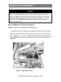
Use and Care of the
Emriver™
River Process Simulator
Little River Research & Design
514 East Main
Carbondale, IL 62901
618-529-7423 www.emriver.com
V. 4.0 low resolution download Dec 2008
© 2009 Little River Research & Design.
All rights reserved.
Warnings
YOU MUST READ AND UNDERSTAND THESE WARNINGS
BEFORE USING THE EMRIVER MODEL
The Emriver model is very heavy when filled with water and sediment. A collapse
of the model supports could severely injure or kill a person. Be absolutely sure you
understand how to use the supports and be very careful when using alternate
supports.
Use only approved support methods. Do not use standard sawhorses, folding
tables, cinderblocks, or other such methods. Despite weight-bearing claims, no
standard production sawhorse is strong enough to safely support the Emriver
model. Sawhorses and folding tables can collapse under dynamic or side loading.
Check all fittings on the aluminum horse supports before each use to be sure they
are secure.
When setting up the box, the supports must be laterally level and aligned. They
must also be aligned with the proper support point underneath the box. Otherwise
the box could be warped or could collapse when loaded.
Never set the box up on a surface with a slope exceeding 8% (7-in drop in 7 ft).
Never use more than 27 gallons (102 liters) of water in the model. The combined
weight of water and sediment in the box could cause the box or supports to
collapse.
Never use more than the provided 185 pounds (83 kg) of sediment in the box, and
do not place any heavy objects in the box.
Never allow people to sit or stand on or in the box. Never get underneath the
loaded box.
Use only the pump and power supply provided with the box. The power supply
should be placed away from the model and any other source of moisture. Read the
manual that comes with the power supply and be certain to connect it to a properly
grounded outlet.
When using 12-volt power from a battery or automobile, always use the fused
connectors provided with the model. Never bypass the fuses.
Be sure you understand the dangers associated with charging and using lead-acid
batteries, and consider using the safer spill-proof batteries.
The box should only be used for its intended purpose as stated herein.
If any part of the box or pumping system is damaged, or you have any doubts
about the electrical or structural safety of the model, or do not understand these
directions, do not use this model.
Table of Contents
Table of Contents
Introduction ........................................................................... 4
Assembly and operation ....................................................... 5
Box setup and slope adjustment ................................ 5
Standpipe and drain ................................................... 8
Reservoir and pump ................................................... 9
Valve assembly ........................................................ 11
Handling sediment ................................................... 14
Notch gage ............................................................... 14
Energy dissipater ..................................................... 15
Disassembly, transport and storage ................................... 16
Maintenance and water quality ........................................... 17
Demonstrations and experiments ....................................... 18
Setup checklist .................................................................... 19
Parts and accessories checklist .......................................... 20
Specifications ...................................................................... 21
Appendix A. Notch gage calibration ................................... 22
All contents copyright 2008
Little River Research & Design
All rights reserved
Emriver and the meandering river logo
are registered trademarks.
Introduction
This manual describes the safe use and maintenance of your Emriver river
process simulator. It is very heavy when filled with modeling media and water,
and could be dangerous if not properly supported, assembled, and operated.
So it’s important that you read, understand, and abide by all the instructions and
warnings in this manual to avoid damage to the model or personal injury. Updates
to this manual and other support for the Emriver model may be found at
www.emriver.com. You can also find support from our user group at
http://groups.google.com/group/emriver.
Figure 1. Parts of the Emriver river process simulator. Power
supply and electrical cords are not shown.
©2008 Little River Research & Design page 4
Assembly and Operation
WARNING
When fully charged with water, the model can weigh in excess of 500 pounds
(227 kg). Dynamic loading during use, caused by someone leaning on the
model, for example, can greatly increase this load. A collapse of the model
supports could be dangerous and seriously damage the model. You must be
certain the model is adequately supported and that you have read and
understand all warnings.
Box Installation and Slope Adjustment
STEP 1 - Set up the supports and adjust slope
To assemble the model, begin by setting up the aluminum "horse" supports.
Note: The box MUST be supported at the two reinforced ribs, and nowhere
else. See Figures 2, 3, and 4. If supports other than those provided are used,
the box must be supported on the support ribs at the four points indicated in
Figure 4.
Figure 2. Support placement.
©2008 Little River Research & Design page 5
Assembly and Operation
STEP 1 (cont.)
The supports should be set up so the crossbars are 52 inches (1.27 m)
apart and aligned as shown in Figure 3 so the box is not twisted around
its long axis.
Figure 3. Correct and incorrect (left) support
alignment. Crossbars, shown in black, must be both
level and parallel when viewed as shown.
On uneven ground use shims made from 3/4" plywood or 2 by 4 scraps
under the horse feet as necessary. The shims should be at least as
large as the footpads for proper support.
Be sure all four feet of each horse are properly supported. One horse
is modified to provide clearance for the reservoir---place the horses so
this opening lies at the appropriate end. See Figures 1 and 2.
©2008 Little River Research & Design page 6
Assembly and Operation
STEP 1 (cont.)
The horses supports provided have a difference in height of about 2.8
inches, yielding a box slope of 5 percent.
The slope of channels in the box will be determined by the position of
the standpipe, so the exact box slope is not necessarily important.
If the supports are not properly aligned, the box will twist when fully
Figure 4. Support points on the box bottom. The support ribs are shown
in grey. The box must be supported at all four points indicated by arrows.
loaded, which may cause damage. To check alignment, look across the
support points as shown in Figure 3. The supports must be both level
and parallel.
Caution: The supports must be properly aligned with the support ribs
on the box before any weight is added to the box. See Figure 4.
STEP 2 -
Install the box
When the supports are level and aligned, place the box on them.
Note: Gaps of more than 0.25 inches (6 mm) between the support ribs and the
horse crossbars indicate the supports aren’t properly aligned.
©2008 Little River Research & Design page 7
Assembly and Operation
STEP 3 - Install the standpipe in the drain assembly
Install the standpipe by sliding it into the drain assembly from the bottom of the
box only. Insert the aluminum handle first.
The seal may be damaged if you insert the standpipe from above.
The standpipe will move
much more freely in the
drain assembly seal when
wet—you may want to
moisten the standpipe
before inserting it.
The drain assembly nut
should not be over
tightened. Some water
should leak from around
the assembly, down the
outside of the standpipe,
and into the reservoir.
This flow allows
‘groundwater’ to exit the
media and improves river
modeling performance.
Figure 5. Insert the standpipe from the box bottom only to avoid damage
to the seal. The standpipe will move much easier when the seal is wet.
©2008 Little River Research & Design page 8
Assembly and Operation
STEP 4 - Position the reservoir
The reservoir should be located as shown in Figure 1 so that the standpipe
will drain into the reservoir.
Using the graduations on the reservoir, fill it with a maximum of 25 - 27
gallons (102 liters) of water. The reservoir is graduated in U.S. gallons.
WARNING
Using more than 27 gallons (102 liters) of water could damage the box or
cause it to collapse. Do not exceed this volume and do not start the pump
until you have filled the reservoir and carefully measured the total volume of
water in the system.
WARNING
When full of water, the reservoir weighs over 200 pounds (91 kg) -- it will be
damaged or destroyed if moved when full.
STEP 5 - Position the sediment trap
Place the sediment trap on the aluminum struts in the reservoir.
STEP 6 - Position the pump
Place the pump, lying on its side, in the bottom of the reservoir.
Check the secondary filter attached to the pump to make sure it is
secure. If the pump is reluctant to prime when started, reorient or shake
it a bit to remove air trapped in its intake. If necessary, clean fine debris
from the secondary filter by removing the filter and back-flushing it with
water.
©2008 Little River Research & Design page 9
Assembly and Operation
STEP 7 - Power the pump
To power the pump, attach the provided 20-foot extension cord to the
pump's power cord. Plug the other end of the cord, which is equipped
with an automotive cigar lighter plug, into the power supply's receptacle.
After all connections are made, the power supply’s switch can be used
to energize the pump.
WARNING
Be sure you understand how to use the power supply. Keep it away
from the Emriver model and other sources of moisture. The
extension cord is provided for this purpose. The power supply is
designed for indoor use only.
WARNING
During normal use, the heat sink on the back of the power supply will become quite
warm. If the heat sink becomes too hot to touch, however, (over 200 degrees F, or 93
C), disconnect it and contact us for service.
Alternately, you may use a nearby automobile for power. The pump
uses about 3.8 amps. Be careful not to excessively discharge the
automobile's battery. Normal automotive batteries will be quickly
destroyed by deeply discharging them, so use only a deep-cycle battery
and the alligator clip wiring harness provided.
You may also use a deep-cycle 12-volt battery. A sealed lead-acid
UB123501 battery with rating of about 32 amp-hours will power the
pump for several hours on a full charge. Large marine batteries (such
as those used for trolling motors) are not necessary.
©2008 Little River Research & Design page 10
Assembly and Operation
STEP 7 (cont.)
WARNING
Be sure you understand how to handle whatever battery you use.
•
Lead-acid batteries produce hydrogen when being charged and can explode.
•
Lead-acid batteries must be maintained and kept charged or they will degrade
over time.
•
Your battery should be in a suitable box to prevent its contacts from shorting on
conductive objects, such as the aluminum parts of the box and its supports.
Note: Both the alligator clip harness and the extension cord are fused.
The extension cord uses a small glass fuse inside the male plug. The fuses
can be checked visually or with a continuity tester if you suspect they are
blown.
Caution: Do not bypass the fuses.
STEP 8 - Attach Valve Assembly
Attach the valve assembly as shown in Figure 1 using the small stud
and wing nut in the valve assembly. Don't over-tighten the wing nut.
Alternately, you may rotate the valve assembly 90 degrees to the right
and use the other hole. Use this option only if you are using the level
rod near the standpipe and the valves get in the way, or if you don’t like
having the valves above the box. If you use this option, you will have to
find some way to secure the tubing between the main valve and notch
gage.
©2008 Little River Research & Design page 11
Assembly and Operation
STEP 9 - Attach and Position Hoses
The 0.5-inch i.d. (13 mm) hose from the bypass valve goes back to the
reservoir (Figure 6). The larger hose from the main valve goes to the
upstream end of the box and the notch gage. Simply lay it inside the
box against the box wall, where it will later be buried by modeling media.
STEP 10 - Operation and adjustment of the valve assembly
Tightness of the valves can be adjusted using the large knurled sleeves.
Keep these sleeves somewhat loose. If these sleeves are too tight,
media grains may cause them to jam. In this case, simply loosen the
sleeves. The modeling media is hard and angular, which is good for
river modeling, but tough on valves. If the valves feel "crunchy" when
turned, they probably have sediment particles lodged inside. Loosening
the sleeves while pumping water through the valves will usually fix this.
Figure 6. Flow pathways for water and media (sediment).
©2008 Little River Research & Design page 12
Assembly and Operation
STEP 10 (cont.)
Note: Some leakage from the valves is preferable to over-tight sleeves.
For servicing or cleaning, disassemble the valves by unscrewing the
sleeves and removing the small metal screws in the handles.
Using the valves
Figure 6 shows the flow pathways for water and sediment in the model.
The valve assembly's Y-manifold feeds both valves. The main valve
directly controls flow to the upper end of the box and thus your river
experiments. The bypass valve sends flow from the pump back to the
reservoir.
Most demonstrations and experiments use only a fraction of the pump's full
output. The bypass valve allows precise control of flow rates and prevents
excessive backpressure on the pump when the main valve is only slightly
open.
To send the pump's full output to the box, fully open the main valve and
completely close the bypass valve.
This is the only setting in which the bypass valve should be fully closed.
From this setting, incrementally opening the bypass valve and closing the
main valve will reduce the flow rate. To completely shut off flow without
turning off the pump, fully open the bypass valve and close the main valve.
The threaded hose fittings at the ends of the hoses are 7/8-inch "garden
hose thread" (GHT) connectors allowing you to use standard garden hoses
to fill and empty the reservoir in field settings. Use a perforated scoop to
return sediment to the box. The secondary filter on the pump (Figure 5)
prevents sediment from entering the pump.
The pump is not affected by small amounts of sediment, but the sediment is
abrasive and large quantities could damage the pump over time. Allowing
sediment to accumulate in the reservoir will not harm the pump. The
secondary filter is sized to allow the pump to function normally even when
completely buried in sediment. However, fine debris such as dirt, lint, and
pollen can accumulate in the media over time and clog this filter. Just give
it a rinse now and then.
©2008 Little River Research & Design page 13
Assembly and Operation
STEP 11 – Fill the Box with Modeling Media (Sediment)
Handling the media
During experiments and demonstrations, sediment leaving the box will
accumulate in the sediment trap. The rate at which the trap filter fills is
highly variable, depending on activity in the box.
When the filter becomes full, use the perforated scoop (which fits nicely into
the trap) to return sediment to the box.
STEP 12 - Assemble the Notch Gage and Energy Dissipater
Attach the 3/4" i.d. (19 mm) line from the valve assembly using the threaded
connectors. The flexibility of the short section of silicone hose on the notch
gage allows some leeway in positioning the gage in the box and protects its
inlet from stress. Put the gage in the upper end of the box as shown in
Figure 1.
Note: Before the first use, and periodically after, the gage must be
calibrated as outlined in Appendix A.
©2008 Little River Research & Design page 14
Assembly and Operation
STEP 13 - Assemble the Energy Dissipater
The dissipater should be placed next to the notch gage to catch the flow
nappe from the gage, as shown in Figure 7.
The energy dissipater induces turbulence in the flow from the notch gage to
bring its energy to a level appropriate for channels in the box. This
minimizes edge effect near the notch gage and gives you as much usable
channel length as possible.
Note: Both the gage and the dissipater should sit on the bare box bottom
with little or no sediment underneath. At very high flows, the dissipater can
be positioned away from the gage in order to catch all the flow.
Figure 7. Notch gage and energy dissipater.
©2008 Little River Research & Design page 15
Disassembly, Transport, and Storage
Moving and storing the Emriver model
As much as 10 gallons (38 l) of "groundwater" will remain in the media and box
after the pump has been turned off and flow at the drain slows to a deceptive
trickle. Before storage of the model, most of this remaining water must be drained
from the sediment. This water can take several hours to drain.
Drainage can be accelerated by removing the standpipe (but not the drain
assembly) and elevating the upper end of the model with a 2-inch shim between
the support rib and the support. It also helps to create a straight channel, cut
down to the box bottom, from the top to bottom of the model. This channel may
remind you of drainage methods used in agriculture.
The sediment is biologically inert and can be removed from the model and stored
damp, though it is best to provide a means for drainage. A 40 or 50-gallon
container with a few holes in the bottom works well. A scrap of plastic filter cloth
over the holes will keep sediment from being lost. Remember, though, that the
sediment may weigh well over 200 pounds (91 kg) when wet.
To prevent growth of mold and bacteria, add 10ml or so of household bleach to the
buckets if you plan to store them wet.
If you leave your Emriver set up for more than a day, we recommend covering it to
avoid contamination of the media by dust and other debris. A white canvas
painter’s drop cloth works very well and allows the media to breathe and dry out.
Just be sure to use some means to prevent the drop cloth from resting directly on
the wet media, or mold growth may occur.
©2008 Little River Research & Design page 16
Maintenance
Maintenance and water quality
Clean plastic parts with mild detergents. Don’t use solvents, which may dissolve
or weaken the plastic. If the PVC tubing is left in the sun while wet, it may support
algae growth and become cloudy. Routing a mild bleach solution through the
hoses after use will minimize this problem. Removing all standing water in the
lines will help as well. If a source of compressed air is available, use it to dry the
lines before storage.
If tubing becomes cloudy or damaged, contact us for replacement. Tubing from
your local hardware store will work, but that supplied with your model is a highquality type that is longer lasting and more flexible.
All bolts on the support horses should be periodically checked for tightness.
Loose or missing bolts will affect the strength of the horses. The bolts should be
as tight as possible while still allowing the horses to fold.
Clean the secondary filter on the pump periodically.
The water in the system should be changed each time it’s used. Dust and debris
will enter it over time and cloud the water, making it more difficult to see sediment
transport processes. If you need to conserve water, add about 30 ml (1 ounce) of
laundry bleach to the reservoir every two days or so, and run the pump to
distribute it through the system. This will prevent algae and bacteria from
colonizing the model. You may also use widely available home water filters to
remove contaminants. Contact us for more information.
©2008 Little River Research & Design page 17
Demonstrations and Experiments
Detailed instructions for using the Emriver can be found in the Emriver Lab
Manual. Here are a few guidelines:
The primary independent variables imposed on your experimental channels are
channel slope and discharge. To gain familiarity with the capabilities of the model,
it’s best to begin by exploring both of these variables at relatively low values.
Slope is controlled by the slope of the box (which is 5% when you use the support
horses on a level surface) and by the elevation of the standpipe. Slope of your
channels is also dependent, of course, on their sinuosity. It is best to begin with
lower slopes. A small laser level can be used to explore the relative elevations of
the upper end of the channel and the standpipe. The modeling media is
manufactured within a range of specifications and its specific gravity can vary from
batch to batch. This may cause slightly different sediment behavior in different
models.
As you are learning to use the model, begin with low flows of from 25 to 50 ml/s.
These flows may seem too low at first glance, but low flows often give the most
interesting results. Higher flows will mobilize all sediment in the channel, which, in
many demonstrations and experiments, will make it difficult to see specific
processes. Try forming a channel with moderate flows of less than 75 ml/s and
then lowering the discharge to find the point at which sediment transport in the
channel ceases. Then work up from this point.
When forming experimental channels, mimic what you see in the field.
Meandering gravel-bed rivers, for example, will have low point bars that slope
gradually up to a floodplain, and relatively steep banks on the outsides of bends.
Routing brief flood pulses through your channels will give them more realistic
characteristics. Remember that your modeled channels should be in a nearequilibrium condition in order to show the effects of disturbances. The guidelines
and videos at www.emriver.com will help you begin.
You may want to add sediment to the small pool that usually forms just
downstream of the energy dissipater. This prevents the upper ends of your
channels from being sediment-starved.
©2008 Little River Research & Design page 18
Setup Checklist
1. Read and understand the warnings in this manual.
2. Find a hotel lobby, gravel bar, or other surface with a slope of less than an 8%.
3. Set up support horses so the crossbars are 52 inches (1.32 m) apart and with a
height difference of 1.5-2.5 inches (38 - 63 mm). Carefully check that the
horses are aligned to prevent twisting of the box. Check the supports for
damage and loose connectors.
4. One of the support horses has an opening for the reservoir–be sure to place
this horse appropriately.
5. Place the box on the supports. Before adding any weight to the box, be sure
that the support ribs of the box are resting on the supports and that there are
no gaps greater than 0.25 inches (6 mm) between the supports and the box’s
support ribs.
6. Attach the valve assembly to the box.
7. Insert the standpipe in the drain assembly so that at least 2 inches (50 mm)
extend inside the box.
8. Place the reservoir under the drain and add the sediment trap.
9. Check the pump’s secondary filter for fine debris. Attach the pump to the valve
assembly and place the pump on the bottom of the reservoir.
10.
Put the notch gage in the box and connect to the main valve’s output hose.
Place the energy dissipater beside the notch gage.
11.
Fill the box with modeling media.
12.
Fill the reservoir with no more than 27 gallons (102 l) of water using the
graduations on the reservoir.
13.
Connect the power supply to the pump, using the 20-foot extension cord to
keep power supply a safe distance from moisture.
14.
Begin experiments and demonstrations.
©2008 Little River Research & Design page 19
Parts and Accessories Checklist
Emriver parts and
accessories checklist
Other parts and supplies you
may want to have on hand
Emriver box
media in six buckets
Emriver User’s Manual
paper towels and mop
shim materials
hand level
Emriver Lab Manual
standpipe
support horses
reservoir
pump and primary filter
valve assembly and hoses
hydraulic shapes
measuring tape
solid scoops (optional)
perforated scoops
sediment trap
sieve
notch gage
energy dissipater
power supply
20' extension cord
alligator clip battery adapter
Emriver level rod and holder
tape measure
laser level
12 volt battery
battery charger
plastic buckets for sediment and water
garden hose
scraper/trowel
notebook
graduated cylinder
stopwatch
household bleach
small towels for drying hands
©2008 Little River Research & Design page 20
Specifications
modeling media (sediment)
dry weight
180 pounds (82 kg)
modeling media material
cryogenically ground melamine plastic,
various colors
sediment specific gravity
1.3 to 1.5
sediment particle size
from 0.02 - 0.09 in. (0.5 - 2.1 mm)
box weight
approx. 65 lbs (29 kg)
water capacity
27 gal (102 liters)
weight of entire system
during use
box size
minimum floor space needed
for demonstration with 12
people
approx. 525 lbs (240 kg)
pump type
12V DC marine pump, rated 800 gph at 3.8
amps. Typical maximum output at notch gage
is 325 ml/s
notch gage capacity
~25 to 350 ml/s
84 x 36 x 6 in. (2.1 x 0.91 x 0.152 m)
12 x 15 ft (3.6 x 4.6 m)
©2008 Little River Research & Design page 21
Appendix A – Notch Gage Calibration
Use and calibration of the Emriver notch gage
The notch gage provided with your Emriver model allows you to precisely measure
flow in the model during experiments and demonstrations. The volumetric flow
rate of water, or discharge, is a fundamental independent variable in river
geomorphology.
Parts of the notch gage are shown in Figure A1. Flow from the notch is
proportional to the water surface elevation (WSE) in the gage. Discharge in your
simulated rivers is determined by measuring the WSE. The baffles in the notch
gage act in combination with the column of water in the gage to reduce currents in
the gage that may affect accuracy.
Figure A2 shows parts of the
head scale, which is used to
measure WSE in the notch
gage. The head scale is
provided with a scale
graduated in millimeters,
though you may change this
scale as described later in
these instructions. The head
scale can be placed on the
rim of the notch gage at any
point beyond 25 mm (one
inch) from the notch opening.
If the head scale is placed
nearer than 25 mm, it may
disturb the lines of flow
exiting the notch gage.
Figure A1. The Emriver notch gage
and energy dissipater.
©2008 Little River Research & Design page 22
Appendix A – Notch Gage Calibration
Before use, the notch gage must be calibrated, i.e. you must establish the
relationship between WSE and discharge. The gage should be placed in the box
in the position in which it will be used. Next, place the head scale in the gage.
Figure A2. The head scale. A paper scale and plastic rod
are held tightly inside the clear plastic tube by a
compressible foam spacer and cap. The scale shown is
graduated in mm.
Fill the gage by using the pump and valve system to route a moderate flow through
the gage so that the WSE reaches the approximate midpoint of the notch.
Gradually decrease flow until it is zero or until the flow nappe is overcome by
surface tension and flow runs down the exterior of the gage. To find the lowest
WSE at which the nappe is free of the outside wall of the gage, increase flow
slightly until the nappe just breaks free of the gage. This point is affected by the
surface tension of the water in the gage, which can be affected by water chemistry,
and can therefore vary. A WSE within 3 or 4 mm of this point is sufficient.
We recommend the SI units of ml/second as the most practical for the range of
flows used in the model. You will need a 2000 ml beaker (or other container with a
volume of at least 1000), a 1000 ml graduated cylinder, a stopwatch, and
notebook.
©2008 Little River Research & Design page 23
Appendix A – Notch Gage Calibration
To begin calibration, use the beaker to capture flow from the gage. Higher
volumes of captured flow per run will yield more accurate measurements. Before
each capture, record the WSE on the head gage. Record the rate of flow by
simultaneously diverting the nappe into the beaker and starting the stopwatch.
After each capture, record the time in seconds and tenths and volume of flow
captured in milliliters, as well as a second reading of the WSE on the head gage.
If the two WSE readings are not the same, the WSE changed during the run and
the data for that run should be discarded. Figure A3 shows a typical data sheet.
Take at least two flow measurements at the first WSE setting. Then adjust the
flow so that the WSE increases by 3 to 5 mm. Allow the flow to stabilize for a few
seconds and take another two or three flow measurements. Continue
incrementally increasing flow and measuring discharge until you reach the full
output of the pump or the capacity of the notch.
The notch gage uses a two-stage notch that allows measuring a wide range of
flows (from about 20 ml/s to 400 ml/s) with a compact gage. The discharge - WSE
curve shows a slight jump at the point of width increase in the notch, so measure
this point carefully. You should also measure discharge when the WSE is just at
the break in notch size, because this is an important reference point.
©2008 Little River Research & Design page 24
Appendix A – Notch Gage Calibration
before
after
volume, ml
840
time,
s
38.2
head scale,
mm
22
head scale,
mm
21
Q, ml/sec
22.0
680
570
610
700
670
960
885
635
760
810
890
31.6
15.8
17.1
14.8
15.8
13.8
12.9
7.0
8.6
7.2
7.9
22
25
26
30
29
37
37
41
41
48
48
22
25
26
30
29
37
37
41
41
48
48
21.5
36.1
35.7
47.3
42.4
69.6
68.6
90.7
88.4
112.5
112.7
640
710
970
880
940
890
840
4.2
4.6
5.8
5.3
4.8
4.6
3.4
56
56
58
58
64
64
70
56
56
59
58
64
64
70
152.4
154.3
167.2
166.0
195.8
193.5
247.1
770
990
855
860
880
3.1
3.3
2.7
2.3
2.4
70
76
76
84
85
70
77
76
85
85
248.4
300.0
316.7
373.9
366.7
notes
lowest possible WSE with free
nappe
at lower point of notch break
Full flow
Figure A3. Typical notch gage calibration data.
©2008 Little River Research & Design page 25
Appendix A – Notch Gage Calibration
Making a custom scale for the notch gage
The head scale is delivered with a paper scale calibrated in millimeters. After
calibrating your gage, you can determine discharge by reading the WSE in mm
and referring to the calibration curve.
Alternately, the outside of the head scale may be marked at a few key flow points
with a suitable marker. The points to be marked will depend upon what the model
is being used for. For basic demonstrations to laypeople, for example, where you
must work quickly and will only use two or three flow rates, you might simply mark
these values on the head scale or notch gage wall with a grease pencil.
Alternately, discharge values may be marked on the paper scale alongside the
millimeter values. Parts of the head scale are shown in Figure A2. To remove the
paper scale, simply pull the plastic cap off the head scale. Custom scales may be
constructed and held in place inside the tube with a very small piece of tape or a 2
mm dot of glue. Hot melt glue works well, and can easily be removed by gently
heating the tube in warm water. Don’t use solvent glues, which may dissolve the
acrylic tube.
For further information and support, visit www.emriver.com .
Care of the notch gage
The gage and head scale should be handled and stored carefully to prevent
damage. The notch is precisely machined, and calibration and accuracy will be
affected if it is damaged. The gage should be stored and transported in the plastic
mesh in which it was shipped. This mesh will both protect the gage and allow it to
air-dry after use. To clean the gage, carefully pull out the baffle assembly and use
non-abrasive rags and mild detergent. Solvents of any kind may dissolve or mar
the plastic.
©2008 Little River Research & Design page 26