1
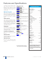
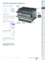
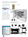
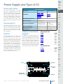
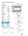
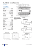
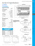
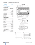
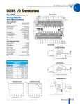
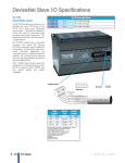
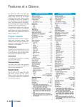
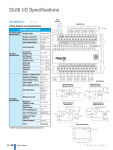
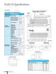
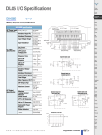
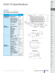
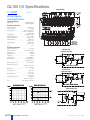
DL105 I/O Specifications
Output point wiring
F1-130DD
<--->
Wiring diagram
and specifications
Power requirements
Voltage range . . . . . . . . . . . . . . . . . . . . . . . . . . .94-240 VAC (30 VA)
. . . . . . . . . . . . . . . . . . . . . . . . . . . . . . . . . . . . .100-240 VDC (30 W)
DC input specifications
Number of input points . . . . . . . . . . . . . . . . . . . . . . .10 (sink/source)
Number of commons . . . . . . . . . . . . . . . . . . . . . . . . . . . .3 (isolated)
Input voltage range . . . . . . . . . . . . . . . . . . . .(X0–X3) 10-26.4 VDC
. . . . . . . . . . . . . . . . . . . . . . . . . . . . . . . .(X4-X11) 10-26.4 VDC or
. . . . . . . . . . . . . . . . . . . . . . . . . . . . . . . . . . . . . . . . . .21.6–26.4 VAC
Input impedance . . . . . . . . . . . . . . . . . . . . . . .2.8 K⏲ @ 12-24 VDC
ON current/voltage level . . . . . . . . . . . . . . . . . . . . .> 3 mA / > 9 VDC
OFF current/voltage level . . . . . . . . . . . . . . . . . .< 0.5 mA / < 2 VDC
OFF to ON response . . . . . . . . . . . . . . . . . . . . . . . . . . .X0-X3: 50 µs
. . . . . . . . . . . . . . . . . . . . . . . . . . . . . . . . . . . . . . . . . .X4-X11: 2-8 ms
ON to OFF response . . . . . . . . . . . . . . . . . . . . . . . . . . .X0-X3: 50 µs
. . . . . . . . . . . . . . . . . . . . . . . . . . . . . . . . . . . . . . . . . .X4-X11: 2-8 ms
Fuses . . . . . . . . . . . . . . . . . . . . . . . . . . . . . . . . . . . . . . . . . . . . . .None
Input point wiring
DC output specification
Number of output points . . . . . . . . . . . . . . . . . . . . . . . . . .8 (sinking)
Number of commons . . . . . . . . . . . . . . . . . .3 (internally connected)
Output circuitry . . . . . . . . . . . . . . . . . . . . . . . . . . . . . . . . . . .MOSFET
Output voltage range . . . . . . . . . . . . . . . . . . . . . . . . . . . . . .5-30 VDC
Peak voltage . . . . . . . . . . . . . . . . . . . . . . . . . . . . . . . . . . . . . .60 VDC
ON voltage drop . . . . . . . . . . . . . . . . . . . . . . . . . . .0.4 VDC @ 0.5 A
Maximum current . . . . . . . . . . . . . . . . . . . . . . . .0.5 A /point (Y0-Y1)
. . . . . . . . . . . . . . . . . . . . . . . . . . . . . . . . . . . . . .1.0 A /point (Y2-Y7)
Maximum leakage current . . . . . . . . . . . . . . . . . . . .15 µA at 30 VDC
Maximum inrush current . . . . . . . . . . . . . . . . . . . . . . . . . . . . . . . . . . .
. . . . . . . . . . . . . . . . . . . . . . . . . . . . . . . . . . . .Y0-Y1: 1.5 A for 10 ms
. . . . . . . . . . . . . . . . . . . . . . . . . . . . . . . . . . . . .Y2-Y7: 3 A for 10 ms
Minimum load . . . . . . . . . . . . . . . . . . . . . . . . . . . . . . . . . . . . . .None
OFF to ON response . . . . . . . . . . . . . . . . . . . . . . . . . . .Y0-Y1: 10 µs
. . . . . . . . . . . . . . . . . . . . . . . . . . . . . . . . . . . . . . . . . . .Y2-Y7: 3.5 µs
ON to OFF response . . . . . . . . . . . . . . . . . . . . . . . . . . .Y0-Y1: 70 µs
. . . . . . . . . . . . . . . . . . . . . . . . . . . . . . . . . . . . . . . . . . .Y2-Y7: 110 µs
External DC power required . . . . . . . . . . . . . . . . . . . . . . .10-30 VDC,
. . . . . . . . . . . . . . . . . . . . . . . . . . . . . . . . . . .@ 30 mA + load current
Fuses . . . . . . . . . . . . . . . . . . . . . . . . .None (external recommended)
Derating chart for DC inputs
Equivalent circuit
high-speed inputs (X0-X3)
Equivalent circuit
standard inputs (X4-X11)
Derating chart for DC outputs
Equivalent output circuit
To other circuits in bank
+V
+
+V
Output
Common
Volume 13
e3-12
Programmable Controllers
1 - 80 0 - 633 - 0405
Features and Specifications
The DL105 micro PLCs contain the CPU,
power supply and I/O all in the same
housing. If you examine the CPU
Specifications table, you’ll see that we
included many features found in our
modular CPUs.
AC-powered units
F1-130AA
F1-130AD
10 AC inputs, 8 DC outputs, 1.0 A/point, two outputs can be
used as 7 kHz pulse output, 0.5 A/point
F1-130AR
Review the specs
10 AC inputs, 8 relay outputs, 7 A/point
Make sure these features can satisfy the
requirements of your application. Since
these units are completely self-contained,
you cannot expand the system or replace
the CPU as you would in a modular
system.
10 DC inputs, 4 inputs are filtered inputs, can also be configured as a single 5 kHz high-speed counter, interrupt input, or
pulse catch input
8 AC outputs, 1.7 A/point
System capacity
System capacity is the ability to accommodate a variety of applications. For ladder
memory, most Boolean instructions require
one word. Some other instructions, such
as timers, counters, etc., require two or
more words. Our V-memory words are
useful for data storage, etc.
Performance
The performance is simply the scan time,
which is the amount of time required to
read the inputs, solve the RLL program
and update the outputs.
F1-130DA
F1-130DD
Communications
All DL105 units offer one RS-232 port,
capable of 9,600 baud.
System capacity
Total memory available (words) . . . . . . . . . . . . . . . . . . . . 2.4K
Ladder memory (words) . . . . . . . . . . . . . . . . . 2,048 EEPROM
V-memory (words) . . . . . . . . . . . . . . . . . . . . . . . . . . . . . . . 384
User V . . . . . . . . . . . . . . . . . . . . . . . . . . . . . . . . . . . . . . . . . 256
Non-volatile user V. . . . . . . . . . . . . . . . . . . . . . . . . . . . . . . 128
Battery backup . . . . . . . . . . . . . . . . . . . . . . . . . . . . . . . . . . . No
Total I/O. . . . . . . . . . . . . . . . . . . . . . . . . . . . . . . . . . . . . . . . . 18
Inputs . . . . . . . . . . . . . . . . . . . . . . . . . . . . . . . . . . . . . . . . . . 10
Outputs . . . . . . . . . . . . . . . . . . . . . . . . . . . . . . . . . . . . . . . . . . 8
I/O expansion . . . . . . . . . . . . . . . . . . . . . . . . . . . . . . . . . . . . No
10 DC inputs, 4 points are filtered inputs, can also be configured as a single 5 kHz high-speed counter, interrupt input, or
pulse catch input
8 DC outputs, 1.0 A/point, 2 outputs can be used as 7 kHz
pulse output, 0.5 A/point
Performance
F1-130DR
RLL ladder style. . . . . . . . . . . . . . . . . . . . . . . . . . . . . . . . . . Yes
RLLPLUS/flowchart style (Stages) . . . . . . . . . . . . . . . . . . Yes/256
Run-time editing . . . . . . . . . . . . . . . . . . . . . . . . . . . . . . . . . Yes
Supports Overrides . . . . . . . . . . . . . . . . . . . . . . . . . . . . . . . No
Variable/fixed scan. . . . . . . . . . . . . . . . . . . . . . . . . . . . Variable
Instructions . . . . . . . . . . . . . . . . . . . . . . . . . . . . . . . . . . . . . . 91
Control relays . . . . . . . . . . . . . . . . . . . . . . . . . . . . . . . . . . . 256
Timers . . . . . . . . . . . . . . . . . . . . . . . . . . . . . . . . . . . . . . . . . . 64
Counters . . . . . . . . . . . . . . . . . . . . . . . . . . . . . . . . . . . . . . . . 64
Immediate I/O . . . . . . . . . . . . . . . . . . . . . . . . . . . . . . . . . . . Yes
Subroutines . . . . . . . . . . . . . . . . . . . . . . . . . . . . . . . . . . . . . No
For/next loops . . . . . . . . . . . . . . . . . . . . . . . . . . . . . . . . . . . No
Timed interrupt . . . . . . . . . . . . . . . . . . . . . . . . . . . . . . . . . . Yes
Integer math. . . . . . . . . . . . . . . . . . . . . . . . . . . . . . . . . . . . . Yes
Floating-point math . . . . . . . . . . . . . . . . . . . . . . . . . . . . . . . No
PID . . . . . . . . . . . . . . . . . . . . . . . . . . . . . . . . . . . . . . . . . . . . No
Drum sequencers . . . . . . . . . . . . . . . . . . . . . . . . . . . . . . . . Yes
Bit of word . . . . . . . . . . . . . . . . . . . . . . . . . . . . . . . . . . . . . . No
ASCII print . . . . . . . . . . . . . . . . . . . . . . . . . . . . . . . . . . . . . . No
Real-time clock/calendar . . . . . . . . . . . . . . . . . . . . . . . . . . . No
Internal diagnostics. . . . . . . . . . . . . . . . . . . . . . . . . . . . . . . Yes
Password security . . . . . . . . . . . . . . . . . . . . . . . . . . Multi-level
System and user error log . . . . . . . . . . . . . . . . . . . . . . . . . . No
10 DC inputs, 4 inputs are filtered inputs, can also be configured as a single 5 kHz high-speed counter, interrupt input, or
pulse catch input
8 relay outputs, 7 A/point
DC-powered units
F1-130DD-D
10 DC inputs, 4 inputs can be used as 5 kHz high-speed
counter, interrupt inputs, or pulse catch inputs
8 DC outputs, 1.0 A/point, two outputs can be used as 7 kHz
pulse output, 0.5 A/point.
F1-130DR-D
10 DC inputs, 4 inputs can be used as 5 kHz high-speed
counter, interrupt inputs, or pulse catch inputs
8 relay outputs, 7 A/point
Instructions and diagnostics
Make sure the unit offers the instructions
you need.
DL105 CPU Specifications
10 AC inputs, 8 AC outputs, 1.7 A/point
Programming
Handheld programmer.....D2-HPP. . . . . . . . . . . . . . . . . <--->
DirectSOFT Programming for Windows
PC-DSOFT5 . . . . . . . . . . . . . . . . . . . . . . . . . . . . . . . . . .<--->
PC-DS100 . . . . . . . . . . . . . . . . . . . . . . . . . . . . . . . . . . . <--->
PC-R50-U (upgrade) . . . . . . . . . . . . . . . . . . . . . . . . . . . <--->
Specialty features
For the DC input and/or DC output
versions, we also offer several high-speed
I/O features.
Contact execution (Boolean) . . . . . . . . . . . . . . . . . . . . . 3.3 µs
Typical scan (1K Boolean)1 . . . . . . . . . . . . . . . . . . . . . . 5-6 ms
Instructions and diagnostics
Communications
Built-in ports . . . . . . . . . . . . . . . . . . . . . . . . . . one, RS-232-C
K-sequence (proprietary protocol) . . . . . . . . . . . . . . . . . . . Yes
DirectNET™ . . . . . . . . . . . . . . . . . . . . . . . . . . . . . . . . . . . . . No
MODBUS master/slave . . . . . . . . . . . . . . . . . . . . . . . . . . . . No
ASCII out . . . . . . . . . . . . . . . . . . . . . . . . . . . . . . . . . . . . . . . No
Baud rate (fixed) . . . . . . . . . . . . . . . . . . . . . . . . . . . 9,600 baud
Specialty features
Filtered inputs. . . . . . . . . . . . . . . . . . . . . . . . . . . . . . . . . . . Yes2
Interrupt input. . . . . . . . . . . . . . . . . . . . . . . . . . . . . . . . . . . Yes2
High-speed counter . . . . . . . . . . . . . . . . . . . . . . . . Yes, 5 kHz2
Pulse output . . . . . . . . . . . . . . . . . . . . . . . . . . . . . . Yes, 7 kHz2
Pulse catch input . . . . . . . . . . . . . . . . . . . . . . . . . . . . . . . . Yes2
Note: Either high-speed input or pulse output
can be used, but not in the same configuration.
1- Our 1K program includes contacts, coils, and scan
overhead. If you compare our products to others,
make sure you include their scan overhead.
2- Input features are only available on units with DC
inputs. Output features are only available on units
with DC outputs.
Volume 13
e3-4
Programmable Controllers
1 - 80 0 - 633 - 0405
DL105 Hardware Features
CPU status indicators
Company
Information
Systems
Overview
Output terminal
block (removable)
Programmable
Controllers
Terminal covers
RUN . . . . . . .ON . . . . . . . . . . . . . . . . . . CPU is in RUN mode
. . . . . . . . . . .OFF . . . . . . . . . . . . CPU is in PROGRAM mode
PWR . . . . . . .ON. . . . . . . . . . . . . . . . . . . . . . CPU power good
. . . . . . . . . . .OFF . . . . . . . . . . . . . . . . . . . . CPU power failure
CPU . . . . . . .ON . . . . . . . . . . . . . . . CPU internal diagnostics
. . . . . . . . . . . . . . . . . . . . . . . . . . . . . . . . has detected an error
. . . . . . . . . . .OFF . . . . . . . . . . . . . . . . . . . . . . . . . . CPU is OK
Field I/O
Software
Output LEDs
6-pin female
connector
Mode control
The DL105 units do not have mode
switches like many of our modular CPUs.
You can set the unit (using special
V-memory locations) so that it will power
up in RUN mode.
Drives
Soft
Starters
Motors &
Gearbox
Steppers/
Servos
Communications port
Protocol . . . . . . . . . . . . . . . . . . . . . . . . . . K-sequence slave
Devices . . . . . . . . . . . . . . . . . . . . . . . . . Can connect with HPP,
. . . . . . . . . . . . . . . . . . . . . . . . . . . . . . . . DirectSOFT, DV-1000,
. . . . . . . . . . . . . . . . . . . . . . . . . . . . . . . . . . . . . C-More Panels
Specs . . . . . . . . . . . . . . . . . . . . . . . . . . . 6P6C RJ12 connector
. . . . . . . . . . . . . . . . . . . . . . . . . . . . . . . RS-232-C, 9,600 baud,
. . . . . . . . . . . . . . . . . . . . . . . . . . . . . . . . . . . . . . . . . Odd parity,
. . . . . . . . . . . . . . . . . . . . . . . . . . . . . Fixed station address (1),
. . . . . . . . . . . . . . . . . . . . . . . . . . . . . . . . . 8 data bits (one start,
. . . . . . . . . . . . . . . . . . . . . . . . . . . . . . . . . . . . . . . one stop bit),
. . . . . . . . . . . . . . . . . . . . . . . . Asynchronous, half-duplex, DTE
C-more &
other HMI
Motor
Controls
Auxiliary 24VDC supply
(AC powered units only)
Input terminal block
(removable)
Input LEDs
CPU status LEDs
Proximity
Sensors
Photo
Sensors
Limit
Switches
Encoders
Current
Sensors
RJ12 Connector Port 1 Pinout
Pin. . . . . . . . . . . . . . . . . . . . . . . . Signal
Pressure
Sensors
1. . . . . . . . . . . . . . . . . . . . . . . . . . . . . . . . . . . . . . . . . . . . . . 0V
2. . . . . . . . . . . . . . . . . . . . . . . . . . . . . . . . . . . . . . . . . . . . . . 5V
3 . . . . . . . . . . . . . . . . . . . . . . . . . . . . . . . . . . . RS-232 Data in
4 . . . . . . . . . . . . . . . . . . . . . . . . . . . . . . . . . . RS-232 Data out
5. . . . . . . . . . . . . . . . . . . . . . . . . . . . . . . . . . . . . . . . . . . . . . 5V
6. . . . . . . . . . . . . . . . . . . . . . . . . . . . . . . . . . . . . . . . . . . . . . 0V
Temperature
Sensors
Pushbuttons/
Lights
Process
Fixed EEPROM memory
Relays/
Timers
The DL105 units offer built-in EEPROM
memory.
Comm.
Terminal
Blocks &
Wiring
NOTE: Terminals accept 16-24 AWG. For 16 AWG, use
type TFFN or Type MTW. Other types of 16 AWG may
be acceptable, but it really depends on the thickness
of the wire insulation.
Power
Circuit
Protection
Enclosures
Tools
Pneumatics
Appendix
Product
Index
Part #
Index
Volume 13
w w w . a u t o m a t i o n d i r e c t . c o m / d l 10 5
Programmable Controllers
e3-5
Dimensions and Installation
It is important to understand the installation requirements for your DL105 system.
This will help ensure that the DL105 products operate within their environmental
and electrical limits.
Installation
Plan for safety
This catalog should never be used as a
replacement for the user manual. The user
manual, D1-USER-M, contains important
safety information that must be followed.
The system installation should comply with
all appropriate electrical codes and standards.
Unit dimensions and
mounting orientation
Use the following diagrams to make sure
the DL105 system can be installed in your
application. DL105 units must be mounted
horizontally to ensure proper airflow for
cooling purposes. It is important to check
these dimensions against the conditions
required for your application. For
example, we recommend that you leave 2"
depth for ease of access and cable clearance; however, your distance may be
greater or less. Also, check the installation
guidelines for the recommended cabinet
clearances.
Temperature probe
2"
50mm
min
Power source
2"
50mm
min
2"
50mm
min
Panel ground terminal
Bus b
ar
Panel
Ground braid
copper lugs
Earth
ground
Panel or single
Point ground
Star washers
Note: There is a minimum of 2" (50mm) clearance required between the panel door or any devices mounted in
the panel door and the nearest DL105 component.
Dimensions and mounting
Environmental Specifications
Storage
Temperature
Ambient
Operating
Temperature
Ambient
Humidity
Vibration
Resistance
Shock
Resistance
Noise
Immunity
Atmosphere
-4ºF to 158ºF (-20ºC to 70ºC)
32ºF to 131ºF (0º to 55ºC)
Units: inches(mm)
3.48
(88.3)
5.12
(129.9)
30% to 95% relative humidity (noncondensing)
MIL STD 810C, Method 514.2
MIL STD810, Method 516.2
NEMA(ICS3-304)
No corrosive gases
3.16
(80.3)
3.63
(92.1)
Volume 13
e3-6
Programmable Controllers
1 - 80 0 - 633 - 0405
Power Supply and Type of I/O
Company
Information
Systems
Overview
Power supply options
Power Supply Options
This product family offers units that
operate on 110/220 VAC and 12/24
VDC. Choosing the power supply is probably the most important consideration
when specifying a DL105 system, since
not all I/O combinations are offered with
each power supply option. The table to
the right provides the I/O choices and
power supply specifications for each type
unit.
Choosing the I/O
The DL105 product family offers several
different combinations of I/O points.
Once you have chosen the power supply
option, you need to choose the unit that
offers the type of I/O points needed in
your application.
Fixed I/O
All DL105 Micro PLCs have “fixed” I/O
that is updated on every scan. This means
that all units have 10 inputs and
8 outputs, regardless of the actual type of
points on the units (DC in/Relay out, DC
in/DC out, etc.) The DL105 micro PLC is
non-expandable, so you cannot add I/O
points. If you are concerned about future
system expansion, check our DL06 (36
base I/O expandable to 100 total I/O), or
the DL205 micro-modular product family.
The DL205 also offers a wide array of
features and flexible I/O arrangements
with several different base sizes.
Specification
AC Powered Units
24 VDC Powered Units
Part Numbers
F1-130AA, F1-130AR
F1-130AD, F1-130DA
F1-130DD, F1-130DR
F1-DVNET-AR, F1-DEVNET-DD
F1-DVNET-DR
F1-130DD-D
F1-130DR-D
Programmable
Controllers
Field I/O
Software
Voltage Withstand (dielectric)
one minute @ 1,500 VAC between primary, secondary and field
ground
Insulation Resistance
> 10 M⏲ @ 500 VDC
External Power Requirement
85-132 VAC (110 nominal)
170-264 VAC (220 nominal)
100-264 VDC (125 nominal)
10-30 VDC
(12 to 24 VDC)
with < 10 percent ripple
Auxiliary 24 VDC Output
500 mA max.
Not available
Maximum Inrush Current
12 A
8A
Maximum Power
30 VA max.
1 A (approx. 10 W)
C-more &
other HMI
Drives
Addresses automatically
assigned
The DL105 uses automatic addressing, so
for the vast majority of applications, there
is no setup required. We use octal
addressing for our products, which means
there are no 8s or 9s. The first eight input
points use addresses X0-X7, and the last
two input points use X10 and X11. If you
plan on using the high-speed counting
features, there is some very minimal setup
required in special V-memory locations.
Soft
Starters
Motors &
Gearbox
Steppers/
Servos
Motor
Controls
AC-powered units
Part No.
I/O Mix
F1-130AA . . . . . . . . . . . . . . . . . . . . . . . . . . . . . . . . . . 10 Ac in
. . . . . . . . . . . . . . . . . . . . . . . . . . . . . . . . . . . . . . . . 8 AC out
F1-130AD . . . . . . . . . . . . . . . . . . . . . . . . . . . . . . . . . 10 AC in
. . . . . . . . . . . . . . . . . . . . . . . . . . . . . . . . . . . . . . . . 8 DC out
F1-130AR. . . . . . . . . . . . . . . . . . . . . . . . . . . . . . . . . . 10 AC in
. . . . . . . . . . . . . . . . . . . . . . . . . . . . . . . . . . . . . . 8 relay out
F1-130DA . . . . . . . . . . . . . . . . . . . . . . . . . . . . . . . . . 10 DC in
. . . . . . . . . . . . . . . . . . . . . . . . . . . . . . . . . . . . . . . . 8 AC out
F1-130DD . . . . . . . . . . . . . . . . . . . . . . . . . . . . . . . . . 10 DC in
. . . . . . . . . . . . . . . . . . . . . . . . . . . . . . . . . . . . . . . . 8 DC out
F1-130DR . . . . . . . . . . . . . . . . . . . . . . . . . . . . . . . . . 10 DC in
. . . . . . . . . . . . . . . . . . . . . . . . . . . . . . . . . . . . . . 8 relay out
Proximity
Sensors
Photo
Sensors
Limit
Switches
Encoders
Current
Sensors
Pressure
Sensors
DC-powered units
I/O Mix
Temperature
Sensors
F1-130DD-D . . . . . . . . . . . . . . . . . . . . . . . . . . . . . . . 10 DC in
. . . . . . . . . . . . . . . . . . . . . . . . . . . . . . . . . . . . . . . . 8 DC out
F1-130DR-D . . . . . . . . . . . . . . . . . . . . . . . . . . . . . . . 10 DC in
. . . . . . . . . . . . . . . . . . . . . . . . . . . . . . . . . . . . . . 8 relay out
Pushbuttons/
Lights
Part No.
Process
Relays/
Timers
Comm.
Terminal
Blocks &
Wiring
AC supply
Output addresses
Power
Circuit
Protection
Indicates group per
common
Enclosures
Tools
Pneumatics
Appendix
24 VDC auxiliary supply
(AC powered units only)
Input addresses
Product
Index
Part #
Index
Volume 13
w w w . a u t o m a t i o n d i r e c t . c o m / d l 10 5
Programmable Controllers
e3-7