1
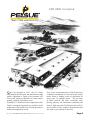
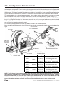
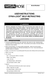
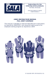
Part #501144-001 Product Manual: PH Series Personnel Hoist IS O 9 0 0 1 Ce r tifie d T.A. Pelsue Company 2500 South Tejon Street Englewood, Colorado, USA 80110 Tel. 800-525-8460 or 303-936-7432 Fax. 303-934-5581 Internet: www.pelsue.com Email: [email protected] Page 2 #501144-001 - Product Manual: PH Series Personnel Hoist - Revision 01 - Date: 10-02-2012 IS O 9 0 0 1 Ce r tifie d S ince our inception in 1963 – the T.A. Pelsue Company has designed and manufactured high quality equipment to improve the personnel efficiency and working conditions in various underground, confined, and outdoor areas. Founded by T. Allen Pelsue, the company has established a continuing reputation for excellence in the production of fine products for a broad spectrum of industry throughout the world. #501144-001 - Product Manual: PH Series Personnel Hoist - Revision 01 - Date: 10-02-2012 Now, in our second generation of family direction, continued commitment to innovation and quality makes Pelsue a leading source of equipment for many types of confined spaces. We specialize in safety, retrieval, fall arrest, ventilation, cable placing, splicing, and maintenance nationally and abroad. With more than 70,000 square feet of facilities available, Pelsue continues the dedication that has made us pre-eminent in this field. Page 3 Table of Contents Section Description Page # 1.0......................................General Information..................................5 1.1...........................Quality Policy 1.2...........................Pelsue Product Warranty 2.0......................................Introduction & Product Information........7 2.1...........................Serial Number 3.0......................................Configuration & Assembly........................8 4.0......................................Safety..........................................................9 4.1...........................Warning Statement 4.2...........................Safety Alert Symbol 4.3...........................General Safety 4.4...........................Operating Safety 4.5...........................Maintenance & Inspection Safety 5.0......................................Operation...................................................12 5.1...........................New Owner or Operator 5.2...........................Pre-Operation Inspection 5.3...........................Applications 5.4...........................System Requirements 5.5...........................Field Operation 6.0......................................Maintenance & Inspection........................21 6.1..........................Maintenance 6.2..........................Inspection 6.3...........................Hoist Inspection Log 6.4...........................Hoist Line Inspection Log 7.0......................................Storage.......................................................35 8.0......................................Contact Information..................................35 Page 4 #501144-001 - Product Manual: PH Series Personnel Hoist - Revision 01 - Date: 10-02-2012 1.0 General Information 1.1 Quality Policy T.A. Pelsue Company Quality Policy OUR GOAL IS THE PURSUIT OF NEVER-ENDING IMPROVEMENT IN PRODUCT QUALITY AND BUSINESS SYSTEMS. Methods to be employed in attaining this goal will include new product quality planning, employee training, and utilization of employee involvement groups to solve problems. In an increasingly competitive marketplace, ensuring customer satisfaction is one of the differentiators that sets you apart from the pack and yields a competitive advantage. Therefore, we will support total customer satisfaction by implementing the ISO 9001 Quality System and providing the necessary atmosphere and training to nurture this concept throughout our organization. We will make every business decision as though the quality of the part or service provided was destined for our own or our family’s use. We will always think Quality First. Every T.A. Pelsue Company employee is expected to commit to this philosophy in the performance of his or her daily tasks. QUALITY FIRST! T.A. PELSUE COMPANY SENIOR MANAGEMENT TEAM #501144-001 - Product Manual: PH Series Personnel Hoist - Revision 01 - Date: 10-02-2012 Page 5 1.2 - Pelsue Product Warranty PELSUE FALL ARREST/ RETRIEVAL PRODUCT WARRANTY • Pelsue products are designed and engineered to perform as stated in published specifications. Quality materials and workmanship are used in the manufacture of this product. With regular maintenance and proper care, Pelsue equipment provides many trouble free hours of operation. • The T.A. Pelsue Company warrants to the buyer that material furnished will conform to specifications and will be free from defects in material and workmanship from the date of shipment to the original buyer, for the period listed by product description at the bottom of this warranty statement. • In the event of failure of any components of a Pelsue product within the warranty period, service must be pre-approved by the T.A. Pelsue Company and service must be performed by the T.A. Pelsue Company Parts and Service Department in Englewood Colorado, or at the option of T.A. Pelsue Company, service may be performed at any designated service center, which may include any authorized service center for the component manufacture. • Damage or failure due to misuse, mishandling, or unauthorized modifications will not be covered by this warranty. Unless otherwise agreed, the T.A. Pelsue Company shall repair or replace the defective components within (30) calendar days of notice of failure. T.A. Pelsue Company’s obligation hereunder, shall be limited to the repair or replacement of the product or component as set forth above, and shall not include any liability whatsoever for damages caused by such failure, including but not limited to consequential or incidental damages flowing from use or lack of use of product. • Any replacement, repair, modification, installation or other service performed by the T.A. Pelsue Company shall be warranted by the remainder of the unexpired period of the warranty, or for a period of (90) calendar days, whichever is longer. • All materials or parts returned for credit or warranty shall be returned only with prior approval, and will be subject to factory inspection before credit is allowed. Parts claimed defective will be replaced upon request and will be invoiced as purchased, subject to credit when the parts claimed to be defective have been received and examined by the factory. • This warranty is expressly in lieu of all other warranties expressed or implied, including any warranties of merchantability or warranties of fitness for any particular use and all other obligations or liabilities in connection with the sale of this equipment. Product Description Warranty Coverage* • Davits and Bases, Life Guard Systems, Fall Arrest Towers,................1 year Hitch Mounts, Mounting Sleeves • Winches................................................................................................1 year • Winch Cable and Rope (not including standard wear and...................3 months tear or misuse or improper storage) • Rope.....................................................................................................3 months • Pelsue Painted or Plated Surfaces.......................................................1 year *From date of shipment to original buyer. T.A. Pelsue Company, 2500 South Tejon Street, Englewood, Colorado 80110, 800-525-8460 Page 6 #501144-001 - Product Manual: PH Series Personnel Hoist - Revision 01 - Date: 10-02-2012 2.0 - Introduction & Product Information Congratulations on your choice of a Pelsue PH Series Personnel Hoist to compliment your entry/retrieval operation. This equipment has been designed and manufactured to exceed confined space requirements and regulations to meet the needs of the discriminating operator for the efficient and safe entry or retrieval of personnel from a confined space. The PH Series Hoist are designed and tested as Mechanical Retrieval/Lifting Devices as defined in OSHA 1910.146 & ANSI Z117.1. PH Series Hoists are approved for use with personnel and are intended to facilitate hoisting and/or rescue & retrieval operations when required. Safe, efficient and trouble-free operation and maintenance for your component or system requires that you or anyone else who will be operating, maintaining, or inspecting the equipment, read, understand and follow all the safety, installation, operation, maintenance and inspection instructions contained in this manual. This manual covers the entire line of the PH Series Personnel Hoist manufactured by Pelsue. Use the Table of Contents or Index as a guide to find specific information. Keep this manual handy for frequent reference and to pass to new operators. Establish a regular training program for experienced and new operators per these instructions. Establish a regular maintenance and inspection program to keep the equipment in top condition. This product is a part of a man rated confined space entry/retrieval system. The user must read, understand and follow the instructions contained in this manual for each component or total system before using this equipment. Establish an appropriate training, maintenance and inspection program for your people and the equipment. Failure to follow these instructions could result in serious injury or death. 2.1 - Serial Number Always give your dealer the serial number of your Pelsue PH Series Personnel Hoist when ordering parts or requesting service or other information. The serial number decal is permanently embossed with a serial number. The serial number decal will appear as shown below in Figure 2a and is located on the Pawl Cover at the drive handle side of the hoist (see Figure 2b). The serial number is also permanently stamped into the base of the hoist. A space has been provided below for the recording of the serial number for future reference. !Do Not Remove the serial number decal or attempt to remove the stamped serial number! Hoist Model:______________________________________ SERIAL NUMBER LOCATION Serial Number :___________________________________ Date of Manufacture (DOM):______________________ Figure 2a: Serial Number Decal #501144-001 - Product Manual: PH Series Personnel Hoist - Revision 01 - Date: 10-02-2012 Figure 2b: Serial Number Decal Location Page 7 3.0 - Configuration & Components The PH Series Hoist is designed to extend and retract a line from a drum that is used as a tether line when performing a confined space entry operation. The PH Series Hoist is equipped with a long-life friction-brake system that is supplemented by a positive-locking double-pawl arrangement. PH Series Hoists are also equipped with a centrifugal “overspeed” brake for redundancy. This feature completely eliminates the possibility of “free-wheeling” in the event that the primary braking system is disabled. Line extension or retraction is controlled by the drive handle which is attached to the drive shaft. The hoist is available with a variety of adapter brackets. These adapter brackets allow the hoist to be easily secured to and removed from various Pelsue and other manufacturer’s rescue & retrieval systems (i.e. tripods , davits, etc,) Line extension (pay out) should occur ONLY when the handle is turned counterclockwise AND a force of AT LEAST 10 lbs. (4.5 kg.) is applied to the hoist line. When there is no tension on the line, turning the handle counterclockwise should NOT cause the drum to move. If the drum rotates under these conditions, the hoist should be removed from service and sent to Pelsue for inspection and possible repair. Line retraction (take up) should occur when the handle is turned in the clockwise direction. Below is a table showing the models of the PH Series Hoist with their corresponding chassis size, line length, and line types. QUICK-RELEASE HOIST DRIVE HANDLE WITH SPEEDER KNOB #501063-A01 GEAR COVER #501143-001 3 1 ANSI Z359.1 COMPLIANT SWIVELING SNAP HOOK SPRING PLUNGER #501087-001 QUICK-RELEASE BRACKET HANDLE Figure 3a: PH Series Hoist Isometric View DETENT PIN #121336-001 Hoist Model 2 Figure 3b: PH Series Hoist Reverse Isometric View Table 3: PH Series Hoist Models & Specs line length line type PH05C 50' (15.2 m) 3/16" Stainless Steel Cable PH07C 70' (21.3 m) 3/16" Stainless Steel Cable PH05R Chassis Size SMALL 50' (15.2 m) ®" Synthetic Rope ®" Synthetic Rope 3/16" "Technora PH07R 70' (21.3 m) PH10C 100 ' (30.5 m) 3/16" Stainless Steel Cable 150' (45.7 m) 3/16" Stainless Steel Cable PH15R 100' (30.5 m) 3/16" "Technora " Synthetic Rope PH20C 200' (60.9 m) 3/16" Stainless Steel Cable 300' (91.4 m) 3/16" Stainless Steel Cable 150' (45.7 m) 3/16" "Technora " Synthetic Rope PH15C PH30C PH15R MEDIUM LARGE 3/16" "Technora ® ® NOTE: The PH Series Hoist is equipped with a safety mechanism which prevents the accidental pay out of large amounts of line. In the absence of constant tension on the line, the drive handle will continue to turn, however, the hoist line WILL NOT pay off of the drum. It will appear that the handle has come loose; THIS IS NOT THE CASE. It cannot come free of the shaft. Simply turning the handle in a clockwise manner will cause the handle to pay in line after a maximum of five (5) revolutions before the lifting brakes are once again engaged. Page 8 #501144-001 - Product Manual: PH Series Personnel Hoist - Revision 01 - Date: 10-02-2012 3.1 - Decal List 2) 501153-001 Decal - WARNING !! Refer to Product Manual For Complete... 1) 501146-001 Decal - Product Specification PH Series Personnel Hoists 3) 121298-001 Decal - Crank Handle Directional 4.0 - Safety Section 4.0 will deal with safety procedures and precautions that are to be addressed and adhered to when employing Pelsue PH Series Personnel Hoists or any other piece of rescue and retrieval equipment. SIGNAL WORDS: Note the use of the signal words DANGER, WARNING and CAUTION with the safety messages. The appropriate signal word for each message has been selected using the following guidelines: DANGER- Indicates an imminently hazardous situation that, if not avoided, will result in death or serious injury. This signal word is to be limited to the most extreme situations or for hidden or unseen hazards. WARNING- Indicates a potentially hazardous situation that, if not avoided, could result in death or serious injury and includes obvious and hidden hazards. It may also be used to alert against unsafe practices. CAUTION- Indicates a potentially hazardous situation that, if not avoided, may result in minor or moderate injury. It may also be used to alert against unsafe practices. You are responsible for the safe operation, maintenance and inspection of your Pelsue man rated confined space entry/ retrieval system. You must ensure that you and anyone else who is going to operate, maintain, inspect or work around the equipment be familiar with the operating and maintenance procedures and related safety information contained in this manual. This manual will take you step-by-step through your working day and alerts you to all good safety and operating practices while using the system. Remember, you are the key to safety. Good safety practices not only protect you but also the people around you. Make these practices a working part of your safety program. Be certain that everyone operating this equipment is familiar with the procedures recommended and follows safety precautions. Remember, most accidents can be prevented. Do not risk injury or death by ignoring good safety practices. • ystem owners must give operating instructions to operators or employees before allowing them to use the equipS ment and at least annually thereafter. • he most important safety device on this equipment is a safe operator. It is the operator’s responsibility to read and T understand all safety and operating instructions in the manual and to follow these. All accidents can be avoided. • person must understand the operation of this equipment and be trained in it’s usage before operating the equipA ment. An untrained operator exposes himself and others to possible serious injury or death. • o not modify the equipment in any way. Unauthorized modification may impair the function and/or safety and could D affect the life of the equipment. • Think SAFETY! Work SAFELY! #501144-001 - Product Manual: PH Series Personnel Hoist - Revision 01 - Date: 10-02-2012 Page 9 4.1 - Warning Statement WARNING! Products manufactured or sold by T.A. Pelsue Company are intended for use by professionals trained and experienced in the use, inspection and maintenance of these products. Paraprofessional users such as volunteer rescue workers and sportsmen involved in risky sports such as climbing and caving will be held to the same standard of experience and training as professionals. Technical rescue, repelling, climbing and the training involved are hazardous activities. Each situation has its own unique conditions and must be evaluated. Effective risk management comes from experience, proper training and good personal judgement. ! WARNING ! Failure to read and heed all labels and instructions may result in injury or death. Inspect all components before and after each use, and remove from service if any damage or defect is found. Keep product free from dirt and moisture. Do not leave a suspended load unattended. Do not exceed maximum rated loads. 4.2 - Safety Alert Symbol SAFETY ALERT SYMBOL This Safety Alert symbol means ATTENTION! BECOME ALERT! YOUR SAFETY IS INVOLVED! The Safety Alert symbol identifies important safety messages on your Pelsue Retrieval Product and in the manual. When you see this symbol, be alert to the possibility of personal injury or death. Follow the instruction in the safety message. Why is this symbol important to you? 3 BIG Reasons: Accidents Disable and Kill. Accidents Cost You Money. Accidents Can Be Avoided. 4.3 - General Safety 1. R ead, understand and follow the User Manual and all safety labels before using, maintaining or inspecting the equipment. 2. R efer to and follow applicable standards and regulations. Comply with requirements of local regulations for your applications. 3. E stablish an equipment-use training program for inexperienced employees. Only trained, competent persons shall use the equipment. An untrained operator is not qualified to operate the system. 4. Have a first-aid kit available for use should the need arise and know how to use it. 5. Provide a fire extinguisher for use in case of an accident. Store in a highly visible place. 6. Install and properly secure all guards and shields before operating. 7. Wear appropriate protective gear. This list includes but is not limited to: • • • • • A hard hat Protective shoes with slip resistant soles Heavy gloves Protective clothing Face Protection Page 10 #501144-001 - Product Manual: PH Series Personnel Hoist - Revision 01 - Date: 10-02-2012 4.3 - General Safety (continued) 8. Review and follow the Pre-Operation Checklist before using a component in the system or system itself. 9. Establish a regular maintenance and inspection program with your equipment and maintain detailed records. 10. Review safety related items and operating instructions with all personnel on a regular basis. 4.4 - Operating Safety 1. Read, understand and follow the User Manual and labels on the hoist before using, maintaining or inspecting the equipment. 2. Train all operators before allowing them to use the hoist. An untrained operator exposes themselves, bystanders and workers to possible serious injury or death. 3. Visually inspect the hoist and all auxiliary components and equipment before using. Correct any problems before using the equipment. 4. Securely anchor the hoist before using. 5. Use only certified anchor and connector components in your system. 6. Use only an approved full body harness for the workers. 7. Always work in teams. One person works in the confined space and the other one pays out the line and reels it in. 8. The attached entrant must not exceed 310 lbs. (140 kg.) or be less then 130 lbs. (59 kg.) on the line during operation. (Including tool belts, etc.). 9. Establish a regular training program for new and experienced workers. 10. Establish a detailed inspection program for your equipment and document the findings. Return the equipment to the manufacturer for re-work if any problems are found. 11. Plan your work program before starting. Have the required people, equipment and procedures available to do the job. 12. Do not use the equipment around physical or environmental hazards. This list includes but is not limited to: • • • • • • • • • Corrosion that may affect the structural integrity of the lifeline or other components. Chemicals which can degrade components in a manner which can not be visually identified. Toxic gases: Rescuers or workers can be killed in toxic environments. Heat or elevated temperatures. Moving machinery: Workers or auxiliary equipment can be contacted by or pulled into moving components. Sharp edges: Workers or the rescue equipment can be injured by or damaged by sharp edges or components. Electrical hazards: Stay away from power lines or components carrying electrical power. Overload: Do not exceed 310 lbs. (140 kg.) during operation. Follow confined space regulations and standards. 4.5 - Maintenance & Inspection Safety 1. R ead, understand and follow the User Manual and labels on the hoist before using, maintaining or inspecting the equipment. 2. S afe operation of this hoist requires a regular inspection program and the maintaining of documented results of these inspections. Follow the inspection procedure contained in this manual and use the inspection form to document the results. 3. Keep instructional and safety labels clean and legible at all times. Clean or replace as required. 4. R emove the equipment from service if a problem is found during the inspection. Return to an authorized repair depot or the factory for service. #501144-001 - Product Manual: PH Series Personnel Hoist - Revision 01 - Date: 10-02-2012 Page 11 5.0 - Operation Section 5.0 will address the basic operation and usage of a Pelsue PH Series Personnel Hoist. Throughout this section and during operation of the PH Series Hoist, the operating safety section of this manual should be constantly referred to and the points address therein should be continually adhered to during all operation. These points have been repeated below. 1. Read, understand and follow the User Manual and labels 12. Do not use the equipment around physical or on the hoist before using, maintaining or inspecting the environmental hazards. This list includes but is not limited equipment. to: 2. T rain all operators before allowing them to use the hoist. An untrained operator exposes themselves, bystanders and workers to possible serious injury or death. 3. V isually inspect the hoist and all auxiliary components and equipment before using. Correct any problems before using the equipment. 4. Securely anchor the hoist before using. 5. U se only certified anchor and connector components in your system. 6. Use only an approved full body harness for the workers. 7. A lways work in teams. One person works in the confined space and the other one pays out the line and reels it in. 8. D o not exceed 310 lbs.(140 kg.) or be less than 130 LBS. (59 KG.) on the line during operation. (Including tool belts, etc.). 9. E stablish a regular training program for new and experienced workers. 10. Establish a detailed inspection program for your equipment and document the findings. Return the equipment to the manufacturer for re-work if any problems are found. C orrosion that may affect the structural integrity of the lifeline or other components. C hemicals which can degrade components in a manner not visually-indentifiable. T oxic gases: Rescuers or workers can be killed in toxic environments. Heat or elevated temperatures. M oving machinery: Workers or auxiliary equipment can be contacted by or pulled into moving components. S harp edges: Workers or the rescue equipment can be injured by or damaged by sharp edges or components. E lectrical hazards: Stay away from power lines or components carrying electrical power. O verload: Do not exceed 310 lbs.(140 kg.) during operation. F ollow confined space regulations and standards. 11. Plan your work program before starting. Have the required people, equipment and procedures available to do the job. 5.1 - New Operators or Owners The Pelsue PH Series confined space entry/retrieval hoist is designed to attach to a person (entrant) and allow them to enter a confined space and assist in exiting if required. Every new operator must read, understand and follow the instructions in the manual. No one should be allowed to use the equipment without training. The training should be reviewed with experienced operators on a regular basis. At regular intervals, perform a detailed inspection of the equipment and document the results. Remove from service if deficiencies are found. Alterations or misuse of this equipment or failure to follow instructions may result in serious injury or death. It is the responsibility of the owner’s organization or operator to read this manual and to train all other operators before they start working with the equipment. Follow all safety instructions exactly. Safety is everyone’s business. By following recommended procedures, a safe working environment is provided for the operator, bystanders and the area around the work site. Untrained operators are not qualified to operate the equipment. Many features incorporated into this equipment are the result of suggestions made by customers like you. Read this manual carefully to learn how to operate the equipment safely and how to set it to perform as intended. By following the operating instructions in conjunction with a good maintenance program, your hoist will provide many years of trouble free service. Page 12 #501144-001 - Product Manual: PH Series Personnel Hoist - Revision 01 - Date: 10-02-2012 5.2 - Pre-Operation Inspection It is necessary to perform a detailed visual inspection prior to using the hoist. If deficiencies are found, remove the hoist from service and return to Pelsue for re-work. This checklist should be used as a guide to determine whether the equipment is in good operating condition prior to using. Equipment that is not in good condition can endanger the safety of the entrant during use. The visual inspection must include but is not limited to the following items. 1. Check that the hoist has no structural defects. 2. Be sure the hoist is clean and the labels are legible. 3. Ensure that the plastic gear cover does not interfere with the gears of the drum. 4. Functional check: a. Ensure that the drive handle can be fully installed on the hoist chassis via the spring plunger on the handle hub. b. Pull on the line and turn the drive handle counter-clockwise to extend the line. c. Turn the drive handle clockwise until 2 clicks of the ratchet is heard to engage the brake. d. Release the drive handle and pull hard on the line. The driveshaft should not move and the line should not extend. e. Pull on the line and turn the drive handle clockwise to retract the line. 5. Inspection of the stainless cable: a. Check the cable for fraying, kinking, cuts, wear, broken wires, weld strike marks or any other defect which may affect the structural integrity of the cable. b. Check that the thimble and the cable crimps are intact and in good condition. c. C heck that the snap hook is in good condition. Be sure that the gate will not open unless the lock is released. The snap should also be free from rust as this is a sign of weakness. OR 5. Inspection of the synthetic rope: a. Check the rope for fraying, kinking, cuts, wear, cut outer sheath or jacket, weld strike marks or a change in diameter of the rope (crushing) or any other defect which may affect the structural integrity of the rope. b. Check that the thimble and the rope terminations are intact and in good condition. c. Check that the snap hook is in good condition. Be sure that the gate will not open unless the lock is released. The snap should also be free from rust as this is a sign of weakness. 6. If the hoist is not in good condition, remove from service and tag for shipment to an authorized repair depot or the factory for re-work. Using a hoist that is not in good condition can lead to a hazardous condition for entrant(s). 7. G o through the detailed inspection procedure on a regular basis (at least annually) per the Inspection Section of this manual. Document the results using the sample form and retain for your files. 8. A detailed inspection is required after each duty cycle. 5.3 - Applications 1. General Pelsue PH Series Hoists are designed to be used in work support or rescue applications. It extends and retracts a line as the handle is turned. When the handle is turned, an internal brake holds the drum and the line will not extend or retract. 2. Scope The hoist works well in both vertical and horizontal applications. However, different mounting, anchoring and support systems are required for each type of application. The user has the responsibility of reading and following the instructions for the other systems in addition to the hoist. Misuse or abuse of any component can create hazards for personnel. 3. Work Support The hoist works well for supporting workers in a boatswains chair or a full body harness (single point suspension). In some applications, a back-up fall arrest may be required. In these applications, a swing angle of less than 30 degrees is recommended. Use only an approved mounting or anchoring system at all times. Use only approved connectors that are equipped with an anti-rollout device. #501144-001 - Product Manual: PH Series Personnel Hoist - Revision 01 - Date: 10-02-2012 Page 13 5.3 - Applications (continued) 4. Emergency Rescue In emergency situations, use the hoist to remove personnel from a hazardous or an unsafe environment. In these situations, a back-up fall arrest system is generally not required. Be sure to use the proper mounting and anchoring system for the hoist. Use only an approved harness for personnel. Always be aware of the system limitations and follow the instructions. 5. Limitations Operators must be aware of several limitations on the use of the hoist whenever it is used and plan their work accordingly. Limitations include but are not limited to: a. Corrosion Do not keep the hoist in an area that has a corrosive atmosphere. Corrosive vapors can be released by sewage plants or in fertilizer plants. Sea water or spray can also cause corrosion to the case, lifeline or other components. Long term exposure to these types of environments will require more frequent inspections to ensure that the function of the unit has not been affected. b. Chemical or Toxic Environments Work environments that contain strong acids, bases or other corrosive chemicals in solutions, sprays or vapors may damage the hoist or auxiliary components. Inspect the unit frequently to detect any damage or change in functionality of the unit. Chemical damage may be difficult to detect visually and periodic lifeline replacement is recommended to insure safety. c. Electrical Hazards Stay away from power lines or other components carrying electrical power. The metal lifeline can conduct electricity if it gets close to or contacts a power line or electrified component. Remember, electricity can jump across an air gap and electrocute personnel using the hoist. Contact your local utility to remove or disconnect the power before working around these components. Contact Pelsue for synthetic rope options to reduce conductivity. d. Load Capacity Do not exceed the hoist capacity of 310 lbs. or 140 kg. or less than 130 lbs. (59 kg.) (includes people, harness, tools, etc.). Do not carry more than one person at a time on the lifeline. Overloading the hoist can exceed the design safety factors and could create hazards. d. Training Do not allow anyone to use this hoist unless they are trained in its limitations and use. Untrained operators can expose themselves and others to hazards. Train new operators before using the unit. Review operating procedures on a regular basis with experienced personnel. 5.4 - System Requirements Pelsue PH Series Personnel Hoists are a component in a confined space entry/retrieval system. The hoist and all auxiliary components must be compatible to prevent creating unexpected hazards. A list of system compatibility requirements includes but is not limited to: 1. Anchorage The hoist is designed to be attached to a Pelsue mounting and support system. These systems do provide the required anchorage strength for the hoist. When using another system or anchorage method, anchorage points must meet or exceed the requirements of the applicable standards or local regulations. Qualified people are required to approve nonstandard anchorage systems before they are used. 2. Connectors Use only approved connectors with sufficient capacity that have an anti-rollout device designed into the snap. Nonapproved connectors can open during use and create unexpected hazards. Do not use them. 3. Personnel Harness Use only an approved full body harness. Do not use a single belt or strap system. Only a full body harness can provide the required support for the body to prevent injury. Page 14 #501144-001 - Product Manual: PH Series Personnel Hoist - Revision 01 - Date: 10-02-2012 5.5 - Field Operation Pelsue PH Series Personnel Hoists are designed for use in many applications including but not limited to personnel riding, rescue or confined space entry/retrieval. It is the responsibility of the operator to be familiar with and follow all applicable OSHA and industry standards on operating guidelines for your project. If you have any questions, consult a qualified person or call the factory. When using the hoist, follow this procedure: 1. Review and follow the Pre-Operation Inspection (Refer to Section 5.3). 2. Inspect the unit prior to each use. Visually check each component to be sure that there is no damaged or missing parts. Check that all systems and components function as intended. Do not use the equipment if any problems are found. 3. Work Planning Plan your entire work project before starting. Consider all the equipment and system requirements and comply with these requirements before starting. Anticipate the needs before, during and after the project is being done and prepare for these needs. Be prepared for the unexpected by planning in advance. Your advance planning list includes but is not limited to: a. Anchorage We recommend mounting the hoist to other Pelsue supporting components and systems to be sure that the anchorage has sufficient strength. Pelsue support and mounting systems are designed to ANSI and OSHA standards. Refer to Structural Manual for specific strengths. When using other manufactures’ anchorages in conjunction with a PH Series Hoist, be sure they meet OSHA or local requirements and have capacities equivalent to or greater than the hoist being used. b. Connectors Connectors, if used, should be equipped with an anti-rollout device to prevent accidental disengagement. Rollout can occur when there is interference between the connector and load that causes the gate or keeper to accidentally open or release. Do not take a chance with safety. Only use approved components. c. Hazards Stay away from mechanical, chemical and electrical hazards. Moving machinery, sharp edges or other mechanical hazards can injure personnel, damage equipment or interfere with the work procedure. Chemical, corrosive or toxic environments can damage equipment or affect the well being of personnel. Electrical power can flow through the equipment and electrocute personnel even if there is no direct contact. Sparks or electricity from welding may damage safety lines and cables. Plan your work and rescue procedures to consider these factors and allow for them. Advance planning will allow the equipment to be used safely in a variety of conditions. d. Line Path Body parts, clothing, tools or other items can get entangled or snagged when going around a corner or over obstacles during the retrieval procedure. Corners or sharp edges can also damage the lifeline as it goes by. Ensure that the hoist line does not come into contact with a heat source or hot object that may damage it. Cautions must be taken when more than one person is tied off separately to prevent the lines from becoming knotted together. Do not step across another hoist line or lifeline. Be prepared to perform a non-entry rescue to assist in the retrieval of a down entrant. e. Vertical Applications For vertical applications, keep the swing-fall angle less than 30 degrees. Serious injuries to personnel can occur if they swing into a solid object. Try to keep the entrant directly below the hoist attachment point at all times. At least two (2) people are required at all times: the entrant and the hoist operator. Always maintain communication to be sure the lifeline is kept taut and that the entrant is not encountering problems. f. Emergency During rescue or emergency procedures, the hoist anchorage must be capable of supporting at least 1500 lbs. (680 kg.). Always use an approved harness when moving people. People can be seriously injured during rescue or in an emergency situation if they are not supported in an approved harness. However, quick response is required in any emergency or rescue operation. #501144-001 - Product Manual: PH Series Personnel Hoist - Revision 01 - Date: 10-02-2012 Page 15 5.5 - Field Operation (continued) 4. Personal Fall Arrest System (PFAS) In some entry/retrieval applications, OSHA, ANSI and local standards require that the entrant be connected to a Personal Fall Arrest System. It is the responsibility of the operator to be aware of these requirements and follow them. Always use a full body harness on the entrant when attached to a PFAS to minimize potential injury to the entrant. Application limitations for the hoist also apply to a PFAS. 5. Installation/Removal Pelsue PH Series Personnel Hoists are most commonly used on or with a Pelsue Davit System. Normally, the hoist is removed from the davit for storage and transporting. When installing or removing the hoist from the davit, follow this procedure: a. Installing: i) Be sure the quick connect mounting bracket is securely fastened to the structure. Refer to appropriate Structure Manual for bracket mounting details. See Figure 5a. Note: Prior to mounting the hoist, the drive handle must be installed to the hoist chassis by pulling on the ring of the spring plunger and inserting the handle. See Figure 5b QUICK CONNECT MOUNTING BRACKET #500101-002 SPRING PLUNGER Figure 5b: PH Series Hoist Drive Handle Installation Figure 5a: Davit System Mounting Bracket ii) A ttach the hoist to the quick connect mounting bracket. Raise the hoist so that the slots on the quick release bracket of the hoist can slide onto the anchoring rod on the quick connect mounting bracket. See Figure 5c. iii) Align the holes on the quick release bracket and the mounting bracket. Secure the hoist using the attached detent pin. See Figure 5d. PIN HOLES DETENT PIN BRACKET SLOTS Figure 5c: PH Series Hoist Mounting Page 16 ANCHORING ROD Figure 5d: PH Series Hoist Detent Pin Figure 5e: PH Series Hoist Fully Mounted #501144-001 - Product Manual: PH Series Personnel Hoist - Revision 01 - Date: 10-02-2012 5.5 - Field Operation (continued) iv) Refer to applicable manuals for detailed instruction on threading the hoist line through pulleys and rollers on the support structure and/or guide blocks (fairleads). v) B e sure the hoist line crimps, thimble, swivel and snap-lock connectors are in good condition and functioning as intended. See Figure 5f. vi) Attach the snap hook to the entrant’s full body harness. See Figure 5h. Figure 5h Figure 5f Figure 5g b. Lifeline Retraction i) When entrant is clear of the confined space and properly supported, disconnect the snap hook from harness. Maintain at least a 10 lb.(4.5kg.) load on the hoist line in order to maintain a neat and tight line coil on the drum. ii) Remove the hoist line from all pulleys and rollers on structure. (Refer to applicable manual). iii) Turn the drive handle to retract the line while maintaining a 10 lb.(4.5 kg.) tension on the line. iv) Retract until the crimps and thimble just touch the drum. CAUTION: Winding the hoist line too far could cause damage to the hoist as the snap becomes entangled with the hoist tensioner system. Damage to the line may also result, affecting the strength of the hoist line. c. Hoist Removal from Support Structure i) Remove the detent pin. See Figure 5i. ii) G rasp the hoist handle and pull the top of the hoist away from the structure while lifting upwards to unhook the slots of the quick release bracket from the anchoring rod on the mounting bracket. See Figure 5j. Store as required. HOIST HANDLE Note: For further storage, the drive handle can be removed from the hoist chassis by pulling on the ring of the spring plunger. See Figure 5k DETENT PIN SPRING PLUNGER Figure 5i: PH Series Hoist Detent Pin Figure 5j: PH Series Hoist Removal #501144-001 - Product Manual: PH Series Personnel Hoist - Revision 01 - Date: 10-02-2012 Figure 5k: PH Series Hoist Drive Handle Removal Page 17 5.5 - Field Operation (continued) 6. Load Attachment a. Prior to attaching the entrant to the hoist line, ensure that the drive handle is installed on the hoist. See Figure 5l & 5m. b. P ull on the snap hook with at least 10 lbs. (4.5 kg.) force while extending the lifeline until there is sufficient slack to attach to the entrant. c. Use two hands when attaching to the entrant. d. Use one hand to apply a steady pull on the lifeline and to steady the snap hook. e. Use the other hand to depress the lock and open the gate. See Figure 5n. f. Insert the entrant D-ring into the hook. WARNING: Always use a full body harness for personnel. g. Ensure that the gate closes on its own and the gate lock clicks into its locked position. DRIVE HANDLE SPRING PLUNGER Figure 5l Figure 5m Figure 5n h. Remove all slack from the lifeline. i. Reverse the above procedure when disconnecting from the load. 7. System Integrity The entrant should always verify the integrity of the attachment and system before entering a confined space. To verify the integrity of the system, follow this procedure: a. Connect the snap hook to the dorsal ring of the full body harness. b. Snug up the lifeline on the hoist drum. c. The entrant should slowly lift their feet off the ground and transfer the weight to the lifeline. d. Be sure the hoist holds in a stationary position. e. B e sure the full body harness is comfortable and does not pinch, chafe or bind. Adjust per manufacturer’s instructions before continuing. f. Do not enter confined space unless connectors, brakes, hoist and harness are functioning properly. DO NOT TEST OVER CONFINED ENTRY. Page 18 #501144-001 - Product Manual: PH Series Personnel Hoist - Revision 01 - Date: 10-02-2012 5.5 - Field Operation (continued) 8. Crew Personnel: A working crew requires the use of at least two (2) people at all times. The entrant who is attached to the end of the lifeline and the attendant who turns the hoist drive handle and guides the lifeline. Each must be properly trained in the use of the equipment for their task. As the entrant enters the confined space, the entrant should maintain constant communication with the attendant operating the hoist. Heavy gloves should be worn by the attendant when guiding the line. The two people must work as a team to get the job done safely and efficiently. 9. Entering Confined Space: When entering confined space, follow this procedure: a. The entrant should move slowly and smoothly into the confined space (either vertical or horizontal). b. The attendant should turn the hoist handle to pay out the lifeline as required. WARNING: Do not use the hoist if turning the handle counter-clockwise pays out line when there is no load applied. Slack may develop in the line and a fall in this situation can result in damage to the hoist as well as injury or death to the personnel. Immediately return the hoist for inspection. c. W earing gloves, place a hand on the lifeline to guide it as it extends. Use your hand to maintain a slight pull on the hoist line at all times. d. F or a vertical entry, maintain the swing angle at less than 30 degrees while working. The entrant can be seriously injured if the swing angle exceeds 30 degrees. See representation below. e. If the entrant is not suspended and there is NO chance of a fall, pay out sufficient line (2 ft. or 6 m. max.) so it is slack and the entrant can work. Hold the lifeline so there is a slight pull on it at all times. f. Extend or retract the lifeline as required to keep the line snug. g. M aintain communication between the entrant and attendant at all times. Be sure each knows what the other is doing. h. D o not travel around corners when entering a confined space. Body parts, clothing, tools or other items can get snagged when proceeding around a corner and over obstacles during the retrieval procedure. Corners or sharp edges can also damage the lifeline as it passes. Be prepared to perform a non-entry rescue to assist in the retrieval of a down entrant. i. If the lifeline becomes tight or slack during entry, communicate with the entrant to determine whether there is a problem. Correct the problem before proceeding. ANCHORAGE LIFELINE #501144-001 - Product Manual: PH Series Personnel Hoist - Revision 01 - Date: 10-02-2012 Page 19 5.5 - Field Operation (continued) 10. Retrieving From Confined Space When retrieving from the confined space, follow this procedure: a. With the drive handle installed, turn the hoist drive handle clockwise to retract the lifeline and retrieve the entrant from the confined space. WARNING: Do not use the hoist if turning the drive handle counter-clockwise retrieves the lifeline. The internal brakes are engaged only when the handle operating direction retrieves the lifeline when the handle is turned clockwise. Should the entrant become caught around a corner or get snagged or tangled, it may be necessary to enter the confined space and assist the original entrant. This should be considered a new entry or rescue and all regulations apply to the new entrant. E.g. Lifeline. Be prepared for a rescue. b. Maintain communications with entrant when preparing to retrieve and during the retrieval process. c. Support the entrant after retrieval and disconnect snap hook. 11. Rescue and Emergencies The hoist is designed for entry and retrieval from confined spaces in rescue or emergency applications. Although fast response is crucial for saving lives, it is still necessary to be aware of and follow all safety and operating procedures. Do not take chances with shortcuts. People’s lives are at stake. Use only trained competent people who know the equipment and can safely rescue people from an emergency situation. 12. Operating Hints a. Follow all applicable OSHA, ANSI and local regulations and standards when using this equipment. b. T rain all operators before allowing them to use the equipment. Conduct regular refresher training sessions with all experienced operators. c. Inspect and maintain the equipment on a regular basis. Remove defective equipment from service. Keep inspection and maintenance records. d. It is recommended that the hoist be used in conjunction with other Pelsue components and systems. These components and systems have the required function, strength and compatibility for all applications. Use them per their instructions. e. R eview and follow the limitations for the equipment. Do not use in corrosive conditions, toxic atmospheres or around mechanical or electrical hazards without taking special precautions. f. P lan your project before starting to work. Anticipate all the normal and unexpected needs relating to equipment and procedures and have them at hand before starting. Advance planning can save time and lives. g. An entrant and attendant are required and must work as a team. Maintain communication at all times. Page 20 #501144-001 - Product Manual: PH Series Personnel Hoist - Revision 01 - Date: 10-02-2012 6.0 - Maintenance & Inspection 1. R ead, understand and follow the User Manual and labelling on the hoist before using, maintaining or inspecting the equipment. 2. A regular inspection program is imperative for all confined space entry/retrieval equipment and to maintain documented results of these inspections. Follow the inspection procedure contained in this manual and use the sample inspection form to document the results. 3. Keep instructional and safety labels clean and legible at all times. Clean or replace as required. 4. Lubricate hoist as per instructions in Section 6. 5. Remove the equipment from service if a problem is found during the inspection. Return to an authorized repair depot or the factory for service. 6.1 - Maintenance The following section will address preventative maintenance points of service, that performed periodically will drastically increase the working life of the PH Series Personnel Hoist. Preventative maintenance will ensure that the PH Series Personnel Hoist is always in optimum working condition. LUBRICANTS 1. Grease: U se a SAE multi- purpose high temperature grease with extreme pressure (EP) performance. Also acceptable is a SAE multi-purpose lithium base grease. 2. Cable (If hoist line is stainless steel cable): Clean with WD-40 or other light de-greaser and wipe with clean rag. MAINTENANCE INTERVALS Daily 1. Visual Inspection Perform a complete visual inspection. Remove from service if a defect is found. Weekly 1. Functional Inspection Perform a functional inspection. Record results and keep documentation. Bi-Annually 1. Lubricate Shaft Bearings Using SAE 30W Oil a. Pinion Shaft (3 locations) See Figure 6a. #501144-001 - Product Manual: PH Series Personnel Hoist - Revision 01 - Date: 10-02-2012 Page 21 6.1 - Maintenance (continued) 2. Lubricate the Cable U se WD 40 to lubricate the cable. Lubricating oil should only be applied to a clean dry cable. Use a stiff bristled brush to remove contaminants from the cable if it is dirty. Allow the oil to penetrate into the cable to reduce internal friction. Wipe the cable dry with a clean cloth as it is being retracted into the hoist. See Figure 6b. b b a a a a a Figure 6a Figure 6b Annually 1. Clean Hoist U se a damp cloth and mild soap to clean the frame and labels of dirt and residue. Be sure the labels are legible. 2. Complete Inspection Perform a complete inspection. Refer to section 6.2.3. Record results and keep documentation. 3. Factory Service Inspection It is recommended that the hoist be serviced by a factory authorized service center or the manufacturer after a period of three years. E xtreme working conditions may indicate the necessity to increase the frequency. Annual servicing shall include but not be limited to an intensive inspection and cleaning of all internal and external components. Failure to provide proper service may shorten product life and could endanger performance or function. Page 22 #501144-001 - Product Manual: PH Series Personnel Hoist - Revision 01 - Date: 10-02-2012 6.2 - Inspection 6.2.1 VISUAL INSPECTION: A complete visual inspection should be performed on the hoist prior to using. The following items should be checked: 1. Labels: Check that all the labels are clean and legible. The PH Series Hoist has 3 labels and a serial number decal (see Figures 6c and 6d). Clean the labels if any are dirty using mild soap and a damp cloth. Replace if any are illegible. Refer to section 2.1 and 3.0 for specific locations of serial number decal and labels. 2. Fasteners: Check that all screws and other fasteners are tight. Tighten if any are loose. Replace if any are missing. 3. Frame: Check the frame and housing for cracks, dents, bends or breaks. Ensure that the gear cover does not interfere with the gears of the drum. If there are major dents or any other structural damage, the unit should be removed from service and returned to the factory for repair. 4. Drive Handle: Check that each handle on the drive handle is tight. If the drive handle is bent or damaged, remove hoist from service. Do not use hoist unless drive handle is fully functional. 5. Corrosion: Check all components for damage from corrosion. Although all components resist corrosion, working in corrosive environments can lead to damage. Inspect the mounting surfaces and fasteners for signs of damage. If damage is found, remove from service and return to the factory for repair. 6. Connectors: Check the hoist line collar and clamp for signs of wear, distortion or fraying. Remove from service and return to the factory for repair if any problems are found. Check the gate and gate lock on the snap hook. Both must open and close easily. See Figure 6e. If they do not, remove from service and return to the factory for service. GATE GATE LOCK Figure 6e Figure 6c #501144-001 - Product Manual: PH Series Personnel Hoist - Revision 01 - Date: 10-02-2012 Figure 6d Page 23 6.2 - Inspection (continued) 6.2.2 FUNCTIONAL INSPECTION A functional check should be performed on the hoist every week or more frequently if used extensively. The following functional tests should be done: (All functional checks must have the drive handle installed on the hoist) 1. Hoist Drive Handle Rotation Direction: The hoist drive handle must turn in the clockwise direction to retract the lifeline and counter-clockwise to extend the lifeline for the internal brakes to engage properly. However, the lifeline should ONLY extend when there is a load placed on the line. With no load present, turning the handle counter-clockwise should not pay out ANY line. If the hoist does, return to the factory for inspection. 2. Snap Hook: Manually check that the swivel on the top of the snap hook turns easily without sticking or binding. Also check that the gate lock and the gate open and close easily without binding or sticking. If any of the features stick or bind, lubricate with a light oil. If sticking or binding persists, remove hoist from service and return to the factory for service. 3. Brake Engagement: The internal brake must hold the line from extending or retracting unless the drive handle is turned. To functionally check this feature, extend the line in 10 foot (3 meter) increments by turning the handle counter-clockwise. At each 10 foot (3 meter) interval, turn the handle clockwise until the line just begins to retract again. This tightens the handle against the brake pads. Pull sharply on the line to ensure that the brake pads are holding securely. If they do not hold, remove the hoist from service and return to the factory for inspection and repair. CAUTION: During this inspection step, if the handle is not turned back clockwise to engage the brake pads, pulling on the line will cause approximately 18 in. (457 mm.) of the line to pay out until the handle tightens by itself. If the handle does not tighten immediately on its own, remove the hoist from service and return to the factory for inspection and repair. 4. Brake Ratchet Mechanism: The hoist is designed with an internal ratchet that engages the brake when the drive handle is turned clockwise. To fully engage the brake, the handle must be turned in the clockwise direction until 2 clicks of the ratchet are heard. If the ratchet does not click when the handle is turned clockwise, remove from service and return to factory for re-work. The ratchet should be silent when the handle is turned counter-clockwise. If the ratchet clicking is heard when the handle is turned counter-clockwise, remove from service and return to the factory for inspection and repair. 6.2.3 DETAILED INSPECTION A detailed inspection should be done on the hoist every year and more often if used extensively. The inspection must include the following, results logged on the sample inspection form and retained in your files should anyone ask to see them. Refer to section 6.2.4 for a sample inspection form. The detailed inspection should include: 1. Visual Inspection Refer to section 6.2.1 for a listing of all items that should be checked visually. Log the results on the inspection form. 2. Functional Inspection: Refer to Section 6.2.2 for a listing of all items that should be functionally checked. Log the results on the inspection form. 3. Detailed Inspection: a. Hoist line Fittings/Snap Hook Check the line fitting on the end of the lifeline. Be sure that it is not, distorted, bent, corroded, worn, loose or cutting into the line. Be sure the line and strands are not frayed or broken. Check the snap hook. Be sure it is not bent, distorted, cracked or worn. Be sure the swivel turns freely and the gate lock and gate open and close easily. Page 24 #501144-001 - Product Manual: PH Series Personnel Hoist - Revision 01 - Date: 10-02-2012 6.2 - Inspection (continued) b. Cable Inspection The cable must be inspected over its full length and the results recorded in the inspection log. Always wear heavy gloves to prevent cuts and slivers while handling the cable. If any strands are broken, remove from service. i) Check for broken wires: Pull the cable out in small segments and flex to check for broken wires. NOTE: The inspection of the cable is all based on the definition of a lay, core, strand and wire. A lay is where a strand makes one complete revolution around the core. The core is the center of the cable itself. A strand is the bundle of wires that move around the core. A wire is a single filament that makes up a strand. See Figures 6f and 6g. Start the inspection at the cable clamp to check for broken wires or strands. Pull out a short segment of cable and turn it while flexing to check for broken wires. WARNING: Review the cable inspection log to determine the location of previously found broken wires or other defects. These previously found defects combined with those found during this inspection may require that the hoist be removed from service. Inspect the entire length of the cable logging the results on the inspection form. When a broken wire is found, remove the protruding end by flexing it back and forth along the length of the cable. The wire will normally break off inside the cable so there are no exposed ends to damage adjacent strands. See Figure 6h. Do not pull on an end or wire with pliers. It can pull the broken end out to expose it. CORE LAY LENGTH STRAND WIRE ONE REVOLUTION OF A STRAND ABOUT THE CORE Figure 6f Figure 6g Figure 6h #501144-001 - Product Manual: PH Series Personnel Hoist - Revision 01 - Date: 10-02-2012 Page 25 6.2 - Inspection (continued) Use the previous inspection logs to determine the total number of broken wires in a lay. See Fig. 6i. Remove the cable and hoist from service when: • • • There are 3 or more randomly distributed broken wires in the cable. There are two or more broken wires in one strand in one lay. There are any broken wires within 1.0 inches (25 mm.) of the cable clamps next to the thimble. Return the hoist to the factory for cable replacement if any of these conditions are met or exceeded. ii) Worn or Abraded Wires: Check for worn or abraded wires. Worn or abraded wires are caused by friction and rubbing against adjacent components and are usually brighter in appearance. Remove from service if any surface wires in one area are worn by 1/3 or more of their diameter. iii) Bulges or Reduction in Diameter: Check for bulges or a reduction of the cable diameter. When these conditions occur, it indicates serious internal cable damage. Remove the unit from service when the cable diameter increases or decreases by 0.05 inches (1.3 mm.). See Fig. 6j. iv) Corrosion: Check for corrosion. Corrosion can be seen as a discoloration of the wires in most cases. Although there is no simple sure way to tell when corrosion has excessively weakened the cable, the inspection personnel must keep in mind that corrosion normally develops on the inside of the cable before it becomes visible on the outside. Have a qualified person assess the damage and determine whether the unit should be removed from service. Pitting is a particularly serious sign of advanced corrosion. Rust along with broken wires in a given area is sufficient reason to remove the unit from service. v) Insufficient Lubrication Check for insufficient lubrication of the cable. Generally this is caused by a build-up of contamination between the strands of cable. Packed grease, dirt, paint or other contaminants prevent the lubricant from getting inside the cable to prevent internal friction and corrosion. If contaminants have filled the grooves, remove from service. REPLACE THE CABLE IF THERE ARE: • 3 OR MORE BROKEN WIRES IN THE CABLE • 2 OR MORE BROKEN WIRES IN ONE STRAND IN ONE LAY NORMAL DIAMETER REDUCED DIAMETER ACCESS CONDITION AT SECTION SHOWING MAXIMUM DETERIORATION FLEXING CAN REVEAL HIDDEN BREAKS Figure 6j Figure 6i Page 26 #501144-001 - Product Manual: PH Series Personnel Hoist - Revision 01 - Date: 10-02-2012 6.2 - Inspection (continued) vi) Snagged Wires and Crushed or Flattened Strands: Check for snagged wires and crushed or flattened stands. These conditions appear when the cable has been pulled around corners or caught between two heavy objects. See Fig 6k. Remove from service and return to the factory for re-work. vii) Unlaying and Bird-Caging: Check for unlaying and bird-caging of strands. This condition appears as the formation of gaps, loops and excessive clearance between strands. See Fig. 6l. If this appears, remove the unit from service and return to the factory for re-work. viii) Kinks and Bends: Check for kinks and bends in the cable. See Fig. 6m. Kinks and bends are created when a loop forms in a slack cable and then it is pulled tight without the loop uncoiling. Remove from service if kinks or bends are formed in the cable and return to the factory for repair. ix) Heat Damage, Torch Burns or Electric Arcs: Check for examples of heat damage, torch burns or electric arc strikes. Localized discoloration, fusing or melting indicate this type of damage. If this is found, remove the unit from service and return to the factory for repair. CRUSHED CABLE Figure 6k: KINKS UNLAYING BENDS Figure 6m BIRD-CAGING Figure 6l #501144-001 - Product Manual: PH Series Personnel Hoist - Revision 01 - Date: 10-02-2012 Page 27 6.2 - Inspection (continued) c. Synthetic Rope Inspection The rope must be inspected over its full length and the results recorded in the inspection log. Always wear heavy gloves to prevent cuts or slivers while handling the rope. If any cuts or frays are present, remove from service. i) Tears or Cuts he synthetic rope consists of an outer jacket and an inner core. Carefully inspect area around rope T crimps for tears or cuts in outer jacket. If the inner core is exposed at all, the hoist must be removed from service for rope replacement. ii) Worn or Abraded Outer Jacket: If the outer jacket shows signs of abrasion, usually resulting in a “fuzzy” appearance, the rope must be replaced. A few threads pulled out of the outer jacket may be clipped off with a pair of scissors, so long as this action does not expose the inner core. iii) Bulges or Reduction in Diameter: Check for bulges or reduction in diameter in the synthetic rope. These indicate a serious condition present in the rope. Remove from service if bulges or reductions are present. iv) Corrosion: Check for corrosion. Corrosion can be seen as a discoloration of the outer jacket, however, this outer jacket could hide corrosion of the inner core. The rope is safe for exposure to water, however, exposure to other chemical environments may affect the strength of the rope. Check with the factory PRIOR to the rope being exposed to such conditions to determine the affect on the rope. If the rope is exposed to an unknown chemical agent, the hoist should be returned to the factory so that the rope may be replaced. v) Knots: Knots forming in the synthetic rope are a source of weakness in the rope. The rope should NEVER be used to tie an item off with a knot. The only way to connect to the synthetic rope is by the snaphook. Any rope that has a knot tied in it should be returned to the factory for replacement. vi) Heat Damage, Torch Burns or Electric Arcs: Heat damage, torch burns or electric arc strikes result in the outer jacket melting and becoming hard or brittle. Often there is damage that is done to the inner core that may not be seen by the naked eye. It is possible to completely sever a synthetic rope lifeline in an environment with several spark sources. Extreme care must be taken under these circumstances and regular rope inspections should take place regularly throughout the day while working to ensure rope integrity. Page 28 #501144-001 - Product Manual: PH Series Personnel Hoist - Revision 01 - Date: 10-02-2012 HOIST CHASSIS #501144-001 - Product Manual: PH Series Personnel Hoist - Revision 01 - Date: 10-02-2012 FUNCTION Serial # Sample form. Copy page to start inspection record book. Fill out using ball point pen. SNAP HOOK lINe ClAmP GAte GAte lOCK SWIVel COrrOSION DAmAGe/WeAr BrAKeS retrACtION eXteNSION QuICK releASe BrACKet GeAr COVer GeArS HANDle(S) teNSIONer SyStem COrrOSION DAmAGe lABelS FASteNerS INSPeCtOr DAte OF INSPeCtION Hoist Model # DOM: 6.3 - Hoist Inspection Log Page 29 6.4 - Hoist Line Inspection Log (Stainless Steel Cable) Hoist Model # Serial # DOM: BrOKeN WIreS CABle lOCAtION* Page 30 meASureD DIAmeter IN 1 lAy IN 1 StrAND OF 1 lAy At FIttINGS COrrOSION eXCeSS WeAr BrOKeN WIre COrrOSION luBrICAtION * Note: Measure location from snap hook #501144-001 - Product Manual: PH Series Personnel Hoist - Revision 01 - Date: 10-02-2012 6.4 - Hoist Line Inspection Log (Synthetic Rope) Hoist Model # Serial # DOM: DAmAGe rOPe lOCAtION* meASureD DIAmeter KNOtS KINKS At FIttINGS COrrOSION * Note: Measure location from snap hook #501144-001 - Product Manual: PH Series Personnel Hoist - Revision 01 - Date: 10-02-2012 eXCeSS WeAr COrrOSION ABrASION HeAt DAmAGe Page 31 Notes: Notes: Notes: 7.0 - Storage Prior to storage, the hoist should be thoroughly inspected and maintained. Repair or replace any worn or damaged components to prevent any unnecessary down time at the next use. Follow this procedure: 1. Thoroughly clean the hoist using a mild soap on the frame and labels, be sure all of the labels are legible. 2. Use a neutralizing solution to clean lifeline. This is particularly important if the unit has been used in corrosive or toxic environments. 3. Perform a complete inspection of the hoist and document the results prior to storage. 4. Lubricate the hoist according to the requirements in this manual. 5. Touch up all nicks and scratches in order to prevent corrosion. 6. Store the hoist in a cool, dry place. 8.0 - Contact Information For More Information... T.A. Pelsue Company 2500 S. Tejon St. Englewood, CO 80110 Toll Free: Telephone: Fax: 1-800-525-8460 1-303-936-7432 1-303-934-5581 Website: www.pelsue.com Email: [email protected] #501144-001 - Product Manual: PH Series Personnel Hoist - Revision 01 - Date: 10-02-2012 Page 35 ISO 900 1 C e rt i f i e d T.A. Pelsue Company 2500 South Tejon Street, Englewood, Colorado, USA 80110 Toll free 800-525-8460 or 303-936-7432 Fax. 303-934-5581 Internet: www.pelsue.com Email: [email protected]