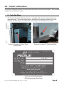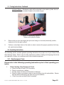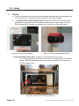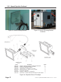
1
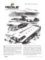
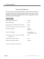
Part #122627-001
OPERATION & SERVICE
MANUAL:
FIBER OPTIC SPLICING TRAILER
(FOST)
ISO 9001 Certified
T.A. Pelsue Company
2500 South Tejon Street
Englewood, Colorado, USA 80110
Tel. 800-525-8460 or 303-936-7432
Fax. 303-934-5581
Internet: www.pelsue.com
Email: [email protected]
ISO 9001 Certified
S
ince our inception in 1963 – the T.A. Pelsue
Company has designed and manufactured high
quality equipment to improve the personnel efficiency and working conditions in various underground, confined, and outdoor areas.
Founded by T. Allen Pelsue, the company has established a continuing reputation for excellence in the
production of fine products for a broad spectrum of
industry throughout the world.
Page 3
Now, in our second generation of family direction,
continued commitment to innovation and quality makes Pelsue a leading source of equipment
for many types of confined spaces. We specialize
in safety, retrieval, fall arrest, ventilation, cable
placing, splicing, and maintenance nationally and
abroad. With more than 70,000 square feet of facilities available, Pelsue continues the dedication that
has made us pre-eminent in this field.
#122607-001 - Operation & Service Manual : FOST - Revision 02 - 10-27-2006
Table of Contents
Section
Description
Page #
1.0...................................... General Information.................................. 5
1.1...........................Introduction
1.2...........................Quality Policy
1.3...........................Warranty Statement
2.0...................................... Trailer Information.....................................8
2.1...........................Trailer Data Plates
2.2...........................Equipment Data
3.0...................................... Trailer Operation & Usage........................ 10
3.1...........................Towing Instructions
3.2...........................Operating Instructions
3.2.1...................Daily Equipment Check
3.2.2...................Starting
3.2.3...................General Operation
3.2.4...................Stopping
4.0...................................... Trailer Wiring............................................. 19
4.1...........................6 Pole Connector - Without Junction Box
4.2...........................Light/Brake Wiring - With Junction Box
4.3...........................6 Pole Connector - With Junction Box
4.4...........................7 Pole Connector - Cole Hersee
4.5...........................6 Pole Connector - Warner
4.6...........................Trailer Wiring Diagram
5.0...................................... Maintenance...............................................26
5.1...........................Trailer Chassis
5.2...........................Genset & Genset Installation
5.3...........................Maintenance Record
6.0...................................... Safety.......................................................... 29
6.1.......................... General Safety
6.2...........................Propane Safety
7.0...................................... Troubleshooting........................................ 31
7.1...........................Electric Brakes Troubleshooting
7.2...........................Genset Troubleshooting
8.0......................................Optional Equipment.................................. 33
8.1...........................Arrowboard (Option #9000)
8.2...........................Shield and Guard Carrier (Option #9004)
8.3...........................Wall Heater (Option #9040)
8.4...........................Cable Clamp (Option #9027)
8.5,,,,,,,,,,,,,,,,,,,,,,,,,,,Other Options
#122627-001 - Operation & Service Manual : FOST - Revision 02 - 10-27-2006
Page 4
1.0 - General Information
The following section contains general information that should be read immediately upon receipt of
your Pelsue trailer.
1.1 - Introduction
ISO 9001
T.A. Pelsue Company ♦ 2500 S Tejon, Englewood, Colorado, 80110, USA ♦ Telephone (303) 936-7432 ♦ Fax (303) 934-5581
Thank you and congratulations on purchasing what we feel is the world’s finest Fiber Optic Splicing
Trailer. Prior to unloading your trailer, please note the following:
Upon receipt of your new Pelsue Fiber Optic Splicing Trailer:
1. Install tongue jack, if not already installed, on the pivot mount provided at the A-frame of trailer
prior to unloading from carrier. This jack is stored inside of the trailer in a cabinet module if not
installed upon receipt. Wheel chocks, if chosen as an option, and corner leveling jacks may also
be stored inside in a cabinet module.
2. Once trailer is safely on the ground with wheels chocked, inspect the exterior to verify damage
has not occurred during transit. NOTE ANY DAMAGE ON BILL OF LADING.
3. Install rear corner leveling jacks if required and, if selected, the optional front leveling jacks.
4. Remove any additional protective padding that may have been installed around the roof top
mounted air conditioner.
5. Open genset compartment and visually inspect genset. Check the oil level prior to starting it.
6. The air conditioner, generator and base trailer carry factory warranties by their respective
manufacturers. We will gladly assist with and coordinate any warranty claims you may have
with any component, whether Pelsue or another manufacturer.
7. An operation & service manual is located inside of the trailer in a wall-mounted holder. Also
provided are manuals pertaining to other pieces of installed equipment. Please make a record
of the trailer VIN number, generator serial number and air conditioner serial number, a place for
recording these numbers is located in section 2.1 of this manual. These numbers will aid us in
identifying your trailer if future warranty or service needs are required.
8. If you have any questions or require assistance with your trailer, now or in the future, please
contact us at 1-800-525-8460.
9. Thank you for purchasing your Fiber Optic Splicing Trailer from the PELSUE COMPANY. We
know it will give you many years of faithful service.
Page 5
#122607-001 - Operation & Service Manual : FOST - Revision 02 - 10-27-2006
1.2 - Quality Policy
T.A. Pelsue Company
Quality Policy
OUR GOAL IS THE PURSUIT OF NEVER-ENDING IMPROVEMENT IN
PRODUCT QUALITY AND BUSINESS SYSTEMS.
METHODS TO BE EMPLOYED IN ATTAINING THIS GOAL WILL INCLUDE
NEW PRODUCT QUALITY PLANNING, EMPLOYEE TRAINING, AND UTILIZATION OF EMPLOYEE INVOLVEMENT GROUPS TO SOLVE PROBLEMS.
IN AN INCREASINGLY COMPETITIVE MARKETPLACE, ENSURING CUSTOMER SATISFACTION IS ONE OF THE DIFFERENTIATORS THAT SETS
YOU APART FROM THE PACK AND YIELDS A COMPETITIVE ADVANTAGE.
THEREFORE, WE WILL SUPPORT TOTAL CUSTOMER SATISFACTION
BY IMPLEMENTING THE ISO 9001 QUALITY SYSTEM AND PROVIDING
THE NECESSARY ATMOSPHERE AND TRAINING TO NURTURE THIS
CONCEPT THROUGHOUT OUR ORGANIZATION.
WE WILL MAKE EVERY BUSINESS DECISION AS THOUGH THE QUALITY OF THE PART OR SERVICE PROVIDED WAS DESTINED FOR OUR
OWN OR OUR FAMILY’S USE. WE WILL ALWAYS THINK QUALITY
FIRST.
EVERY T.A. PELSUE COMPANY EMPLOYEE IS EXPECTED TO COMMIT
TO THIS PHILOSOPHY IN THE PERFORMANCE OF HIS OR HER DAILY
TASKS.
QUALITY FIRST!
T.A. PELSUE COMPANY SENIOR MANAGEMENT TEAM
#122627-001 - Operation & Service Manual : FOST - Revision 02 - 10-27-2006
Page 6
1.3 - Warranty Statement
Pelsue Product Warranty:
All Pelsue products are warranted against defects in materials and workmanship in
accordance with their individual warranty statement. Warranty does not cover: normal
wear and tear, modifications, improper storage, corrosion, or user neglect. Equally
excluded from the warranty are damgage due to accidents, negligence and uses for
which the product was not designed.
Warranty Coverage*
Pelsue General Workmanship
3 years
Body/Frame/Skeleton
6 years
Running Gear (not including bearings or brakes)
5 years
Other Structure (Doors, Windows, Interior Finish, etc.) 1 year
Gensets (Onan Brand)
2 years or
2000 hours
Gensets (Honda Brand)
2 years (engine)
1 year (electrical & frame)
Other Components (AC, Lights, Circuit Breakers
Cabinets, etc.)
1 year
Pelsue Painted or Plated FInishes
1 year
Ventilation Ducts (Blower Hoses)
3 months
*From date of shipment to original buyer.
Page 7
#122607-001 - Operation & Service Manual : FOST - Revision 02 - 10-27-2006
2.0 - Trailer Information
This section will describe where to find important trailer data such as Serial Numbers. Also provided
is space for recording of this data.
2.1 - Trailer Data Plates
The Pelsue FIber Optic Splicing Trailer is equipped with a serial number plate and a
trailer data plate. The serial number plate is mounted just inside the curbside door on the
cabinets, the data plate is mounted on the outer body on the streetside front corner.
Figure 2a. Location of Trailer Serial
Number Plate.
Figure 2b. Location of Trailer Data Plate.
F. O . S . T.
Figure 2c. Serial Number Plate
(Record Appropriate Data Here)
#122627-001 - Operation & Service Manual : FOST - Revision 02 - 10-27-2006
Page 8
2.1 - Trailer Data Plates Continued
1588
ST205/75R15
825
345
3500
15 X 6JJ
1820
50
F. O . S . T.
Figure 2d. Trailer Data Plate
(Record Appropriate Data Here)
Note:
- Portions of the above data plates have been left blank to allow information specific to
each trailer to be filled in by the owner.
Depending on options & rating selected:
- The GVWR of the 11 foot trailer (EL & SE series) can be between 2268 KG & 3175 KG
(5000-7000 LBS.)
- The GVWR of the 13 foot trailer (EX & SX series) is 3175 KG (7000 LBS)
2.2 - Equipment Data
Certain installed components have serial numbers of their own that should be
recorded for future reference. Space is provided below for the recording of
important serial numbers.
A.C. SERIAL NO.
GENSET SERIAL NO.
Page 9
#122607-001 - Operation & Service Manual : FOST - Revision 02 - 10-27-2006
3.0 - Trailer Operation & Usage
3.1 - Towing Instructions
The FOST may be equipped with either a Lunette Eye or a Ball Coupler for a hitching mechanism,
depending upon selected options.
Figure 3a. Lunette Eye
Figure 3b. Ball Coupler
Before Towing the Pelsue Fiber Optic Splicing Trailer please follow the hitching instructions
provided below.
1.
To couple the trailer to the tow vehicle utilize the trailer’s tongue jack in order to vertically
align the trailer’s coupler with the tow vehicle’s hitch point (the height of the eye or coupler
may have to be adjusted within the hitch channel, via the two mounting bolts, in order to
achieve proper vertical alignment for a level trailer towing stance).
Note: The lunette eye or ball coupler supplied with your trailer is mounted within a channel allowing for height adjustment of the hitch. The hitch is fastened within this channel using 2x) 5/8-11
UNC x 4-1/2” long Grade 5 Hex Head Cap Screws and 2x) 5/8-11 UNC center-lock nuts. CenterLocking nuts utilize a deformed thread mechanical fastening system, the nut and accompanying
screw are good for a single use only. If height adjustment of hitch is needed, new Grade 5 cap
screws and new center-lock nuts must be used. The new fasteners should be torqued to 135 ftlbs. Care should be taken so as not to overtighten the fastener, any threaded fastener can
fracture due to excessive tightening torque!
2.
Back the tow vehicle to the trailer;
Lunette Eye - Until the trailer’s lunette eye rests inside the vehicle’s open pintle
hook.
OR
Ball Coupler - Until the trailer’s ball coupler is directly above the vehicle’s ball
hitch.
#122627-001 - Operation & Service Manual : FOST - Revision 02 - 10-27-2006
Page 10
3.1 - Towing Instructions Continued
3.
Lower the trailer tongue with the tongue jack until the lunette eye contacts the base of the
pintle hook or until the ball coupler fully recesses onto the ball hitch.
4.
Close the pintle hook or ball coupler and insert the locking pin.
5.
Connect the safety chains to the tow vehicle by crossing the chains underneath the trailer
tongue. Ensure chains are of proper length in order to allow for turning of the vehicle.
6.
Connect the trailer light connector to the receptacle on the tow vehicle.
7.
Check the operation of the breakaway device by removing the pin from the box by pulling on
the cable. Connect the breakaway device (if-equipped) to a secure point on the back of the
tow vehicle by making a secure loop with the cable. Finally, re-insert the breakway pin completely into the breakaway device. The breakaway device will activate the trailer brakes if the
trailer becomes separated from the tow vehicle. Such a device, in operational condition, is
required in most areas for such a trailer.
! CAUTION ! - Do not secure the breakaway cable at the same location as the safety chain
hooks or at any point where there are sharp edges that could damage the cable. The safety
hooks or other sharp edges can sever the cable in a trailer breakaway situation causing nonoperation of the trailer brakes.
Electric Brakes - Breakaway cable will be attached to the breakaway
device (black box) located on the curb side of the trailer tongue.
Figure 3c. Breakaway Device for
Trailers with Electric Brakes
Page 11
#122607-001 - Operation & Service Manual : FOST - Revision 02 - 10-27-2006
3.1 - Towing Instructions Continued
Hydraulic Brakes - Breakaway cable will be attached to the master cylinder lever at
the top of the brake actuator located on the trailer tongue.
Figure 3d. Breakaway Device for
Trailers with Hydraulic Brakes
8.
Remove the pin from the tongue jack pivot and swing to its stored (horizontal) position,
insert pin to lock the jack in place.
9.
Perform a visual light check of the trailer in order to ensure the proper operation of all stop,
tail, and directional lights.
3.2 - Operating Instructions
The following section contains general operating instructions for proper use of your Pelsue Fiber
Optic Splicing Trailer. Refer to this for daily maintenance checks, starting and stopping instructions
and operation of lights, air conditioners and other installed equipment.
3.2.1 - Daily Equipment Check
Please refer to the following operating instructions prior to first operating your
trailer.
I.
Before Starting: Daily Equipment Check
a. Check fuel and oil levels, fill if necessary.
b. Check connections on battery.
c. Visually inspect all wires and fuel lines for damage.
d. Check to make sure exhaust outlet is clear and away from all combustibles. Ensure
that the silencer and piping are tight and in good condition.
e. Check tire pressures and inflate as needed.
#122627-001 - Operation & Service Manual : FOST - Revision 02 - 10-27-2006
Page 12
3.2.2 - Starting
II.
Starting
a. Check control panel to be sure that all the system switches and circuit breakers are
in the off position. The genset must be started in a no load condition.
b. - If equipped with remote electric start: Locate the control panel or remote start
panel (refer to figures 3e and 3f) inside the curbside door of your trailer, hold the
Start/Stop switch in the start (up) position for 5 seconds or until engine starts.
Figure 3e. Onan Control Panel
Figure 3f. Honda Remote Start Panel
- If equipped with electric start: Locate the control panel on the genset.
- For Onan generators: Open door of aluminum housing and remove access
panel. Hold the Start/Stop switch in the start (up) position for 5 seconds or
until the engine starts.
Figure 3g. Onan Control Panel at Genset
Page 13
#122607-001 - Operation & Service Manual : FOST - Revision 02 - 10-27-2006
3.2.2 - Starting Continued
- For Honda generators: Open curbside door of aluminum housing, turn the
fuel valve lever to the ON position, lever is located just under the fuel tank at the
trailer side, left, of the generator. Insert the key and turn the engine
switch to the START position and hold it there for 5 seconds or until the engine
starts, refer to figure 3h for key location.
Figure 3h. Honda Control Panel at Genset
- If equipped with pull start: turn the fuel valve lever to the ON position, lever is
located just under the fuel tank at the trailer side, left, of the generator. Locate the
starter rope on the side of the generator, pull the grip lightly until resistance is felt,
then pull briskly.
c. Normally the engine will start within 3 seconds. However, if the engine fails to start
after cranking for 5 seconds, release the switch. Wait for the engine to come to a
complete stop before attempting to restart. Do not crank the engine continuously for
more than 10 seconds at a time.
* NOTE: Replace insulated access panel on Onan Genset units immediately after starting.
Overheating will occur if genset is operated with access panel removed.
#122627-001 - Operation & Service Manual : FOST - Revision 02 - 10-27-2006
Page 14
3.2.3 - General Operation
III.
General Operation
a. Breakers:
- All circuits on this trailer are breaker protected, the breaker box is located on the
wall just inside the curbside door. A drawing of the breaker box is shown below in
figure 3i. Check breakers first when equipment does not work.
Part #
103803-000
103804-000
26E-023800
26E-026200
100919-002
44E-017400
122635-708
122635-406
122635-103
112794-001
112795-001
112574-001
112576-001
121863-001
Description
WIRE - 10 GA, BLACK
WIRE - 10 GA, GREEN
WIRE - 10 GA, WHITE
WIRE - 10 GA, RED
GROMMET - RUBBER, 2-1/8” ID, 2-1/2” GR.DIA.
PLUG - SNAP-IN-BLANK, .5” DIA, NICKEL PLATED STEEL
LABEL - BREAKER POSTIONS 7-8, FOST BREAKER BOX
LABEL - BREAKER POSITIONS 4-6, FOST BREAKER BOX
LABEL - BREAKER POSITIONS 1-3, FOST BREAKER BOX
DECAL - “CAUTION, HIGH VOLTAGE”
DECAL - “CAUTION, OPERATE GENSET ONLY...”
CIRCUIT BREAKER - 20 AMP, SINGLE POLE, INDIVID TRIP
CIRCUIT BREAKER - 15 AMP, SINGLE POLE, INDIVID TRIP
CONTROL BOX ASSEMBLY - MOBILE INSTALL. W/ONAN
Item #
16
15
14
13
12
11
10
9
8
7
6
5
4
3
Figure 3i. Breaker Box/Control Panel
b. Genset:
- Your trailer can be equipped with a wide range of generators. For specific operating instructions on your generator please refer to the generator manual included with
the trailer.
- For trailers equipped with portable generators the streetside door on the aluminum
housing will need to be open while the genset is running to allow for proper exhaust
gas ventilation and cooling, this is shown in figure 3j on the next page. The curb
side door may be closed after starting if desired.
Page 15
#122607-001 - Operation & Service Manual : FOST - Revision 02 - 10-27-2006
3.2.3 - General Operation Continued
Figure 3j. Doors Open for operation on Select Series Genset Housing
c. Wall Vent:
Your trailer is equipped with an exhaust fan located on the streetside wall. This fan
runs continuously while the generator or shore power connection is supplying
voltage to the trailer. There is a fuse for this fan located on the control panel. The
fuse is labeled “Wall Vent Fuse”, if the fan fails to operate, check the fuse first and
replace if necessary.
d. Air Conditioner:
Your trailer is equipped with a 13,500 BTU, 120 VAC, rooftop mounted air conditioner. For operating instructions refer to the manual for the air conditioner, included
with the trailer.
e. Floodlight:
Most trailers are equipped with a 500-Watt, halogen quartz, repositionable work light.
There is always a storage bracket located inside the trailer, as shown in figure
3k. Multiple brackets can be mounted on the trailer’s exterior, the most common
locations are shown in figure 3l. Refer to figure 3m for an exploded view diagram
and parts list.
#122627-001 - Operation & Service Manual : FOST - Revision 02 - 10-27-2006
Page 16
3.2.3 - General Operation Continued
Figure 3k. Interior Storage Bracket
Part #
109581-001
112688-001
102720-001
100405-004
26E-005700
110666-001
44E-007600
104161-001
Figure 3l. Exterior Mounting Bracket
Locations
Description
Item #
SPACER - FEMALE FLOOD LIGHT MOUNTING BRACKET
10
FITTING - COUPLING, ANCHOR, 1/2” FNPT
9
FLOODLIGHT BRACKET HOLDER
8
STRAIN RELIEF - WATERTIGHT, 1/2” HUB
7
CORD & PLUG SET - 16/3 S0, 12 Ft. Lg. RATED
6
FLOODLIGHT BRACKET
5
LOCKNUT - CONDUIT, 1/2” (TIGER NUT)
4
FLOODLIGHT - 500WATT QUARTZ HALOGEN, FIXTURE & BULB
3
Figure 3m. Exploded View of Floodlight
Page 17
#122607-001 - Operation & Service Manual : FOST - Revision 02 - 10-27-2006
3.2.4 - Stopping
IV.
Stopping
a. Turn off all system switches and circuit breakers.
b. Run the genset at no load for 5 minutes to allow the engine to cool down.
c. Hold the Start/Stop switch, located inside or at the genset depending on options, in
the stop (down) position, or turn the key at the genset to the OFF postion, until the
genset completely stops.
d. Turn the fuel valve lever to the OFF position on the genset, if equipped.
#122627-001 - Operation & Service Manual : FOST - Revision 02 - 10-27-2006
Page 18
4.0 - Trailer Wiring
The following section contains information on the overall wiring of the trailer.
4.1 - 6 Pole Connector - Without Junction Box
Shown in figure 4a is the standard plug without a junction box, included with most select
series trailers
Figure 4a. Wiring Diagram - Trailer Lights & Brakes
(Without Junction Box)
Page 19
#122607-001 - Operation & Service Manual : FOST - Revision 02 - 10-27-2006
4.2 Light/Brake Wiring - With Junction Box
The following is a diagram of the trailer wiring up to the junction box, located on the tongue of the
trailer, the three sections that follow will contain three different plug configurations and the color
code for them up to the junction box.
Figure 4b. Wiring Diagram - Trailer Lights & Brakes
(Shown up to Junction Box)
#122627-001 - Operation & Service Manual : FOST - Revision 02 - 10-27-2006
Page 20
4.3 6 Pole Connector - With Junction Box
Figure 4c. Wiring Diagram - 6 Pole Round Trailer Plug
Page 21
#122607-001 - Operation & Service Manual : FOST - Revision 02 - 10-27-2006
4.4 7 Pole Connector - Cole Hersee
Figure 4d. Wiring Diagram - 7 Pole Round Trailer Plug
#122627-001 - Operation & Service Manual : FOST - Revision 02 - 10-27-2006
Page 22
4.5 6 Pole Connector - Warner
Figure 4e. Wiring Diagram - 6 Pole Warner Plug/Socket
Page 23
#122607-001 - Operation & Service Manual : FOST - Revision 02 - 10-27-2006
4.6 Trailer Wiring Diagram
Figure 4f. Wiring Diagram - FOST
#122627-001 - Operation & Service Manual : FOST - Revision 02 - 10-27-2006
Page 24
4.6 Trailer Wiring Diagram Continued
Figure 4f. Wiring Diagram - FOST
Page 25
#122607-001 - Operation & Service Manual : FOST - Revision 02 - 10-27-2006
5.0 - Maintenance
The following section covers maintenance of the trailer and the trailer’s installed components.
5.1 Trailer Chassis
Body & Frame: Pelsue fiber optic splicing trailers are constructed utilizing an all aluminum frame
and body structure. Aluminum has been chosen for its strength, lightweight, and corrosion resistance. The aluminum body structure will provide many years of reliable service while not being
plagued by rust as will it’s lesser steel counterparts. The aluminum chassis will require little to no
maintenance except for the occasional washing in order to remove road debris and salt spray that
may prematurely weather and wear the aluminum surfaces.
Running Gear: Pelsue fiber optic splicing trailers utilize simple and reliable rubber torsion axles
in a tandem setup for their running gear. The trailer hubs are equipped with an exclusive feature
that allows the greasing of the axle hubs without removing the wheels or hubs from the trailer.
Consult the included trailer chassis manual regarding procedures and intervals for required maintenance and service on the trailer chassis and running gear.
5.2 Genset & Genset Installation
Wiring: Wiring connections between the trailer and genset and the battery and genset should
be checked periodically to ensure tight and complete connections. Any loose connections, worn
insulation, or broken wires must be replaced immediately. Periodically, the battery posts should
be lubed with high-quality dielectric grease in order to minimize corrosion of the battery terminals.
Fuel System: Fuel lines, whether gasoline or propane, should be visually inspected at regular
intervals. Any chaffing of propane or fuel lines will require immediate replacement. A gasoline fuel
pump (on EL & EX gasoline models) is located underneath the trailer tongue deck at the curbside
of the trailer, periodically this fuel pump should be checked for damage and proper operation.
Genset: Required maintenance and service intervals will vary widely between makes and models
of genset. The user should consult the manufacturers genset operation manuals (included with
trailer) for the required service procedures and intervals. Complete manufacturer’s factory parts,
service and technical manuals are available through Pelsue for all gensets and engines.
5.3 Maintenance Record
Provided on the next two pages is a maintenance record table intended for use in recording
service procedures for further reference. Performed maintenance procedures can be recorded
within the following table. Additional pages can be copied and inserted if desired. In addition,
a decal version of the table has been supplied on the interior surface of the curbside door of the
trailer, if it is preferable to record service procedures at the trailer itself. Additional maintenance
record decals (part #103991-001) are available from Pelsue.
#122627-001 - Operation & Service Manual : FOST - Revision 02 - 10-27-2006
Page 26
5.3 Maintenance Record Continued
See Your Generators Owners Manual for
Service Requirements and Intervals
Date
Hours
Page 27
Service Performed
Initials
#122607-001 - Operation & Service Manual : FOST - Revision 02 - 10-27-2006
5.3 Maintenance Record Continued
See Your Generators Owners Manual for
Service Requirements and Intervals
Date
Hours
#122627-001 - Operation & Service Manual : FOST - Revision 02 - 10-27-2006
Service Performed
Initials
Page 28
6.0 - Safety
The following section covers general safety guidelines to follow when using the Pelsue Fiber Optic
Splicing Trailer.
6.1 General Safety
The trailer is equipped with several warning labels, please read and heed all warnings affixed to
the trailer.
Figure 6a. Caution Decal # 112795-001
Figure 6b. Caution Decal # 112794-001
Figure 6c. Decal # 112793-001
Page 29
#122607-001 - Operation & Service Manual : FOST - Revision 02 - 10-27-2006
6.2 Propane Safety
MANY FIBER OPTIC SPLICING TRAILERS ARE EQUIPPED WITH PROPANE FUELED
GENERATORS. THE FOLLOWING ARE SOME GENERAL SAFETY GUIDELINES TO FOLLOW
WHEN WORKING WITH & AROUND PROPANE.
- Propane is dangerous, as is ANY fuel because of its very nature and purpose - it is FLAMMABLE.
Read and follow the safety precautions when using any propane-fueled system.
- USE COMMON SENSE! Most accidents can be avoided by using common sense and concentrating
on the job to be done.
- AVOID SUBJECTING PROPANE TANKS TO EXCESSIVE HEAT AND HARD ABUSE. Propane
tanks should never be placed close to a fire, and should be kept out of direct sunlight if possible.
Exercise care in handling to avoid dropping or abusive treatment.
- Prior to connecting the propane supply to any equipment, verify that the supply pressure is
regulated down to the input requirements of the equipment.
- ALWAYS CHECK FOR LEAKS AFTER CONNECTING OR DISCONNECTING PROPANE TANK.
The distinctive odor of propane gas should alert that a connection is leaking; check for leaks by
applying a solution of soapy water at each connection. NEVER CHECK FOR LEAKS WITH AN
OPEN FLAME! An undetected leak can cause extreme danger as a potential explosion hazard.
- Before shutting off hose-connected equipment, first turn off the fuel at the tank and allow the fuel
in the hoses and piping to evacuate and burn. Then switch off the equipment.
- ALWAYS KEEP THE PROPANE TANK IN AN UPRIGHT POSITON WHILE IN USE.
- FOR OUTDOOR USE ONLY. Always maintain adequate ventilation when operating a propane
system; the system discharges lethal carbon monoxide gases.
- Keep surrounding area free of all combustible material. Never light or relight a propane system if
the surrounding air is saturated with excessive gas.
- Never transport or store equipment while it is connected to its fuel source. Make sure that the
regulator or valve on the propane tank is tightly closed prior to transport. Always disconnect propane
from system prior to transporting.
- USE PROPANE FUEL ONLY. Do not use natural gas or other fuels in equipment intended only for
propane fuel.
NOTE: The information presented herein, while not guaranteed, was prepared by technical personnel and is true and accurate to the
best of our knowledge. This information is not intended to be all-inclusive as the manner and conditions of use, handling, storage and
other factors may involve other or additional safety or performance considerations. Safe handling and use remains the responsibility
of the customer. No suggestions for use are intended as, and nothing herein shall be construed as, a recommendation to infringe
any existing patents or to violate any Federal, State or local laws.
#122627-001 - Operation & Service Manual : FOST - Revision 02 - 10-27-2006
Page 30
7.0 - Troubleshooting
The following section contains information on troubleshooting & diagnosing some problems that
may be encountered with the trailer.
7.1 Electric Brakes Troubleshooting
Problem
1. No Brakes
2. Intermittent or
Surging Brakes
3. Weak Brakes
4. Grabby or
Locking Brakes
5. Dragging
Brakes
Possible Cause
Remedy
a. Open circuit
a. Check for broken wires, loose connections, improper grounding, faulty connector plug between trailer and vehicle.
b. Improperly wired or inoperative controller
b. Rewire controller. Check controller
operation.
c. Poor brake adjustment
c. Adjust brakes
d. Short circuit
d. Check electrical circuit
a. Inadequate trailer ground
a. Check for proper grounding
b. Broken magnet lead wire
b. Check magnet, replace if necessary
c. Loose wheel bearing
c. Check and adjust bearing
a. Poor connection
a. Check for clean & tight connections
b. Poor ground
b. Do not ground through trailer hitch
c. Short circuit
c. Check electrical circuit
d. Worn or defective magnet
d. Replace
e. Poor brake adjustment
e. Adjust brakes
a. Grease on lining
a. Check for contamination. Replace seal
and lining.
b. Controller not modulating
b. Replace
c. Loose parts in brakes
c. Check for broken springs, loose rivets,
etc.
a. Brakes not adjusted
a. Check brake adjustment, adjust if necessary
b. Electrical defect in controller
b. Correct or replace
c. Hydraulic defect in controller
c. Correct or replace
Figure 7a. Electric Brake
Troubleshooting Table
Page 31
#122607-001 - Operation & Service Manual : FOST - Revision 02 - 10-27-2006
7.2 Genset Troubleshooting
Troubleshooting procedures will vary widely between different makes and models of genset. The
appropriate genset owner’s manual, supplied with the trailer, should be consulted in order to correctly diagnose engine and/or generator problems.
Onan CMM Models: Onan CMM model gensets are the most commonly installed units on Pelsue
fiber optic splicing trailers. Onan CMM models are programmed with a comprehensive set of diagnostic and troubleshooting codes internally. These codes are displayed via a series of flashing
lights displayed on the genset’s primary start/stop switch. This switch can be observed by removing the access panel located at the front of the genset. Instructions for observing and defining the
troubleshooting codes are supplied in the “troubleshooting” section of the Onan Operator’s Manual
supplied with the trailer.
#122627-001 - Operation & Service Manual : FOST - Revision 02 - 10-27-2006
Page 32
8.0 - Optional Equipment
8.1 Arrowboard (Option #9000)
A popular option on the Pelsue fiber optic splicing trailer is the 14-light telescoping and
swiveling arrowboard. The arrowboard is useful in alerting motorists to and directing them around
the worksite. The arrowboard is powered by 12VDC power supplied by the onboard genset starting battery. The arrowboard has several different settings which are displayed on the face of the
control box. The control box is usually mounted on the front interior wall of the trailer (see figure
8b).
The arrowboard is raised and lowered by turning the handle of the manual hand winch
located on the arrowboard stanchion. The arrowboard should always be lowered during transport
of the trailer. The arrowboard can also swivel 360 degrees via its swiveling mount. To swivel the
arrowboard, pull the spring-loaded handle located at the base of the plastic signboard. While the
handle is pulled, the signboard can be rotated. There are locking detents at 90 degree intervals in
order to secure the arrowboard at various rotations.
**Note: The arrowboard control box is equipped with a main power toggle switch on its bottom
surface. When not in use, the main power switch should be placed in the “OFF” position. Even if
the arrowboard is not in operation, a slow drain will occur on the battery if the main power toggle
switch (located at the bottom) is not placed in the “OFF” position.
Figure 8a. Trailer w/ Arrowboard Installed
Page 33
Figure 8b. Interior Arrowboard Control Box
#122607-001 - Operation & Service Manual : FOST - Revision 02 - 10-27-2006
8.2 Shield and Guard Carrier (Option #9004)
A shield and guard carrier is an optional piece of equipment that may be installed at the
front of the trailer. This option provides a mounting point for a manhole shield (ring) and guard
(fence). Straps are supplied with this option in order to secure the shield and guard during
transport of the trailer.
Figure 8c. Shield and Guard Carrier
8.3 Wall Heater (Option #9040)
An available option for the fiber optic splicing trailer is a wall mounted heater. The heater is
240 VAC powered and provides 2000 Watt or 6820 BTU of heat. The heater is usually mounted
on the front interior wall of the trailer near the breaker box. The heater is installed on a dedicated
circuit with a 2-pole 20 Amp breaker located at the breaker box. The heater is equipped with a fan
and has an adjustable heat setting knob located on the face of the heater.
Figure 8d. Wall Mounted Heater
#122627-001 - Operation & Service Manual : FOST - Revision 02 - 10-27-2006
Page 34
8.4 Cable Clamp (Option #9027)
Mounted cable clamps are an available option for the Pelsue fiber optic splicing trailer.
These clamps can mount in a variety of locations depending upon customer requirements.
Usually these clamps are located at the cable access doors at the rear and curbside of the trailer.
These clamps, when mounted, effectively hold cables in position and minimize the possibility of
cable movement during a splice.
In order to place a cable in the clamp, lift up on the two red levers on either side of the
clamp, this action will decompress the toggles. At this point, remove the center hold down bar and
lay the cable on the gripping rubber surface. Replace the center hold down bar and depress the
two red levers to compress the toggles and the clamping mechanism. The clamping action can be
adjusted for differing thicknesses of cable by adjusting the threaded rod and nuts located at each
of the rubber feet of the toggle mechanisms.
Figure 8e. Cable Clamp Open
Page 35
Figure 8f. Cable Clamp In Use
#122607-001 - Operation & Service Manual : FOST - Revision 02 - 10-27-2006
8.5 Other Options
Option #
Description
9000
Arrowboard Option - 14 Light, Telescopic/Swivel Forward Mount
9001
Cabinet Option - Additional Left Hand Single Door
9002
Tie Down Option - Recessed Floor Mount (6X)
9003
Propane Bottle Option - Telco Specification 40 LB. (2X)
9004
Shield & Guard Carrier Option - Front Exterior Mount
9005
CRT Monitor Stand Option - Wall Mounted Swing Away
9007
Cabinet Option - Additional 4 Drawer Module
9008
Wheel Chock Option - Model #5669 (1X) With Holder (1X)
9009
CD Stereo Option - Under Overhead Cabinet, AM/FM/CD/SPEAKERS
9010
Ball Coupler Option - 2-5/16” Ball Heavy Duty Channel Mount
9011
Tie Down Option - Recessed Floor Mount (8X)
9012
Light Bar Option - 8 Light Directional, Rear Mount
9014
Cassette Stereo Option - Under Overhead Cabinet, AM/FM/CASS/SPKRS
9015
Gas Monitor Option - Hard Wired Wall Mount
9016
Arrowboard Option - Fixed 10 Light, Trailer Roof Mount
9017
Stabilizer Jack Option - Additional 2 Rear Corner Jacks
9018
Portable Heater Option - 120 VAC, 5120 BTU, 1500 Watt
9019
Spare Tire & Carrier Option - ST205/75R15 with 5 X 4-1/2” B.C.
9020
Propane Bottle Option - RV Type 40 LB. (2X)
9021
Propane Bottle Option - RV Type 40 LB. With Level Gauge (2X)
9022
Warner Socket Option - 6 Pole With Junction Box
9023
Cone Holder Option - Exterior Vertical Mount, Lockable
9024
Fire Extinguisher Option - 5 LB. A:B:C, Wall Mount Bracket
9025
First Aid Kit Option - OSHA 25 Person WIth Wall Bracket
9026
12VDC Power Tap Option - Wall Mounted
9027
Cable Clamp Option - Bench Top Mounted, Formed Aluminum
9028
Closet Module Option - Installed
9029
Cole Hersee Trailer Plug Option - 7 Pole With Junction Box
9030
Ball Coupler Option - 2” Ball Heavy Duty Channel Mount
#122627-001 - Operation & Service Manual : FOST - Revision 02 - 10-27-2006
Page 36
8.5 Other Options Continued
Option #
Description
9031
Hitch Lock Option - Ball Coupler, Blaylock Type #TL33
9032
Floodlight Option - 500 Watt Halogen, 1X Interior & 2X Exterior Brackets
9033
Safety Center Option - Fire Extinguisher & First Aid Kit, Trailer-Mounted
9034
Remote Start Option - Honda Portable Genset, Interior Trailer-Mounted
9036
Hitch Lock Option - Lunette Eye, Blaylock Type #TL60
9037
Floodlight Option - 55 Watt, 12VDC, Exterior Mounted With Switch
9038
Counter & Storage Option - Across the Aisle, Drop-in
9039
Propane (LPG) - Bottle Option, Aluminum, Telco Spec., 40#
9040
Wall Mounted Heater Option - 240 VAC, 6820 BTU, 2000 Watt
9041
Warner Cable Option - 6 Pole Socket With Double-Ended 4’ Cord
9042
Pollack Trailer Plug Option - 7 Pole Round WIth Junction Box
9043
Economy Gas Monitor Option - Household Hardwired CO Detector
9044
Security System Option - Doors, Windows, Genset Compartment & Vibration
9045
Manhole Safety Kit Option - 4000A, 1325P, AIRPAC15 & PELCHECK-MAX401K
Page 37
#122607-001 - Operation & Service Manual : FOST - Revision 02 - 10-27-2006
PAGE INTENTIONALLY LEFT BLANK
#122627-001 - Operation & Service Manual : FOST - Revision 02 - 10-27-2006
Page 38
PAGE INTENTIONALLY LEFT BLANK
Page 39
#122607-001 - Operation & Service Manual : FOST - Revision 02 - 10-27-2006
T.A. Pelsue Company
2500 South Tejon Street, Englewood, Colorado, USA
80110
Toll free 800-525-8460 or 303-936-7432 Fax. 303-934-5581
Internet: www.pelsue.com Email: [email protected]