1
Agilent 75000 Series C
Agilent E1441A
Function/Arbitrary Waveform Generator
User/Service and SCPI Programming Manual
Where to Find it - Online and Printed Information:
System installation (hardware/software) ............VXIbus Configuration Guide*
Agilent VIC (VXI installation software)*
Module configuration and wiring .......................This Manual
SCPI programming .............................................This Manual
SCPI example programs .....................................This Manual, Driver Disk
SCPI command reference ..................................This Manual
Register-Based Programming.............................This Manual
VXIplug&play programming ............................VXIplug&play Online Help
VXIplug&play example programs .....................VXIplug&play Online Help
VXIplug&play function reference......................VXIplug&play Online Help
Soft Front Panel information ..............................VXIplug&play Online Help
VISA language information................................Agilent VISA User's Guide
Agilent VEE programming information.............Agilent VEE User's Manual
*Supplied with Agilent Command Modules, Embedded Controllers, and VXLink.
*E1441-90003*
Manual Part Number: E1441-90003
Printed September 2012
Printed in Malaysia E0912
Contents
Agilent E1441A Function/Arbitrary Waveform Generator User’s Manual
Edition 3
AGILENT TECHNOLOGIES WARRANTY STATEMENT..................................... 7
Safety Symbols ............................................................................................................. 8
WARNINGS................................................................................................................. 8
Chapter 1
Agilent E1441A
Function/Arbitrary Waveform Generator Module Setup ....................................... 13
General Information.................................................................................................... 13
Setting the Module Address Switch............................................................................ 14
Interrupt Priority ......................................................................................................... 15
Installing into the Mainframe ..................................................................................... 15
Faceplate Indicators and Connectors .......................................................................... 16
Initial Operation .......................................................................................................... 17
Example Programs .............................................................................................. 18
Chapter 2
Agilent E1441A Application Information ................................................................. 19
Functional Capabilities ............................................................................................... 19
Output Configuration .......................................................................................... 19
Amplitude Modulation (AM) .............................................................................. 28
Frequency Modulation (FM) ............................................................................... 30
FM Carrier Waveform Shape .............................................................................. 31
Burst Modulation ................................................................................................. 33
Frequency-Shift Keying (FSK) Modulation ....................................................... 40
Frequency Sweep ................................................................................................ 43
Arbitrary Waveforms .......................................................................................... 46
Built-In Arbitrary Waveforms ............................................................................. 48
Phase-Lock Capabilities (Opt 001) ..................................................................... 49
Triggering the Function Generator ...................................................................... 52
System-Related Operations......................................................................................... 55
Error Conditions .................................................................................................. 55
Self-Test .............................................................................................................. 55
Memory Locations .............................................................................................. 56
Firmware Revision Query ................................................................................... 56
SCPI Language Version Query ........................................................................... 56
Power-On and Reset State ................................................................................... 57
Application Program Examples .................................................................................. 58
C Language Programs ......................................................................................... 58
Compiling and Linking a C Program .................................................................. 58
Example Programs .............................................................................................. 58
Chapter 3
Agilent E1441A SCPI Command Reference ............................................................. 65
CALibration ................................................................................................................ 73
DATA ......................................................................................................................... 77
Contents
3
FORMat ...................................................................................................................... 84
MEMory...................................................................................................................... 85
OUTPut....................................................................................................................... 87
PHASe ........................................................................................................................ 90
[SOURce:] .................................................................................................................. 92
APPLy Commands ..................................................................................................... 96
FM COMMANDS .................................................................................................... 104
Frequency-Shift Keying (FSK) Commands ............................................................. 108
Selecting an Arbitrary Waveform............................................................................. 110
STATus..................................................................................................................... 117
SYSTem.................................................................................................................... 120
TRIGger .................................................................................................................... 121
IEEE 488.2Common CommandReference .............................................................. 124
Agilent E1441A Power-On and Reset State ............................................................. 130
SCPI Command Quick Reference ............................................................................ 131
Appendix A
Agilent E1441A Specifications .................................................................................. 135
Appendix B
Agilent E1441A Error Messages .............................................................................. 141
Execution Errors ....................................................................................................... 141
Self-Test Errors......................................................................................................... 147
Calibration Errors ..................................................................................................... 147
Arbitrary Waveform Errors ...................................................................................... 149
Option 001 Phase-Lock Errors ................................................................................. 151
Appendix C
Agilent E1441A Function Generator Tutorial ........................................................ 153
Direct Digital Synthesis ............................................................................................ 153
Signal Imperfections ................................................................................................. 155
Output Amplitude Control ........................................................................................ 156
Floating Signal Generators ....................................................................................... 157
Attributes of AC Signals........................................................................................... 157
Modulation................................................................................................................ 158
Appendix D
Service Procedures ..................................................................................................... 163
Closed-Case Electronic Calibration.......................................................................... 164
Agilent Technologies Calibration Services .............................................................. 164
Calibration Interval ................................................................................................... 164
Time Required for Calibration.................................................................................. 164
Automated Verification and Calibration Procedures................................................ 164
Recommended Test Equipment ................................................................................ 165
Test Considerations................................................................................................... 165
Performance Verification Tests ................................................................................ 166
Self-Test ............................................................................................................ 166
Quick Performance Check ................................................................................ 167
4
Contents
Performance Verification Tests ......................................................................... 167
Frequency Verification ............................................................................................. 167
Function Gain and Linearity Verification................................................................. 168
DC Function Offset Verification .............................................................................. 168
AC Amplitude Verification ...................................................................................... 169
Amplitude Flatness Verification ............................................................................... 171
AM Modulation Depth Verification ......................................................................... 172
Optional Performance Verification Tests ................................................................. 172
Square Wave Duty Cycle Verification .............................................................. 172
Distortion Verification ...................................................................................... 173
Calibration Security Code......................................................................................... 174
Unsecuring the Function Generator (Lost Security Code) ................................ 175
Calibration Count...................................................................................................... 176
Calibration Message ................................................................................................. 176
General Calibration/Adjustment Procedure.............................................................. 177
Aborting a Calibration in Progress ........................................................................... 178
Frequency and Burst Rate Adjustment ..................................................................... 178
Function Gain and Linearity Adjustment ................................................................. 179
AC Amplitude Adjustment (High-Z)........................................................................ 180
Modulation Adjustment ............................................................................................ 181
AC Amplitude Adjustment (50 Ohms)..................................................................... 182
DC Output Adjustment ............................................................................................. 184
Duty Cycle Adjustment ............................................................................................ 185
AC Amplitude Flatness Adjustment ......................................................................... 185
Error Messages ......................................................................................................... 188
Performance Test Record.......................................................................................... 190
Test Limits ......................................................................................................... 190
Measurement Uncertainty ................................................................................. 190
Test Accuracy Ratio (TAR) .............................................................................. 190
Index .............................................................................................................................. 199
Contents
5
6
Contents
Certification
Agilent Technologies, Inc. certifies that this product met its published specifications at the time of shipment from the factory. Agilent
Technologies further certifies that its calibration measurements are traceable to the United States National Institute of Standards and
Technology (formerly National Bureau of Standards), to the extent allowed by that organization's calibration facility, and to the
calibration facilities of other International Standards Organization members.
AGILENT TECHNOLOGIES WARRANTY STATEMENT
PRODUCT: E1441A
DURATION OF WARRANTY: 1 year
1. Agilent warrants Agilent hardware, accessories and supplies against defects in materials and workmanship for the period specified
above. If Aglent receives notice of such defects during the warranty period, Agilent will, at its option, either repair or replace products
which prove to be defective. Replacement products may be either new or like-new.
2. Agilent warrants that Agilent software will not fail to execute its programming instructions, for the period specified above, due to
defects in material and workmanship when properly installed and used. If Agilent receives notice of such defects during the warranty
period, Agilent will replace software media which does not execute its programming instructions due to such defects.
3. Agilent does not warrant that the operation of Agilent products will be interrupted or error free. If Agilent is unable, within a reasonable
time, to repair or replace any product to a condition as warranted, customer will be entitled to a refund of the purchase price upon prompt
return of the product.
4. Agilent products may contain remanufactured parts equivalent to new in performance or may have been subject to incidental use.
5. The warranty period begins on the date of delivery or on the date of installation if installed by Agilent. If customer schedules or delays
Agilent installation more than 30 days after delivery, warranty begins on the 31st day from delivery.
6. Warranty does not apply to defects resulting from (a) improper or inadequate maintenance or calibration, (b) software, interfacing, parts
or supplies not supplied by Agilent Technologies, (c) unauthorized modification or misuse, (d) operation outside of the published
environmental specifications for the product, or (e) improper site preparation or maintenance.
7. TO THE EXTENT ALLOWED BY LOCAL LAW, THE ABOVE WARRANTIES ARE EXCLUSIVE AND NO OTHER
WARRANTY OR CONDITION, WHETHER WRITTEN OR ORAL, IS EXPRESSED OR IMPLIED AND AGILENT
SPECIFICALLY DISCLAIMS ANY IMPLIED WARRANTY OR CONDITIONS OF MERCHANTABILITY, SATISFACTORY
QUALITY, AND FITNESS FOR A PARTICULAR PURPOSE.
8. Agilent will be liable for damage to tangible property per incident up to the greater of $300,000 or the actual amount paid for the product
that is the subject of the claim, and for damages for bodily injury or death, to the extent that all such damages are determined by a court
of competent jurisdiction to have been directly caused by a defective Agilent product.
9. TO THE EXTENT ALLOWED BY LOCAL LAW, THE REMEDIES IN THIS WARRANTY STATEMENT ARE CUSTOMER’S
SOLE AND EXLUSIVE REMEDIES. EXCEPT AS INDICATED ABOVE, IN NO EVENT WILL AGILENT OR ITS SUPPLIERS BE
LIABLE FOR LOSS OF DATA OR FOR DIRECT, SPECIAL, INCIDENTAL, CONSEQUENTIAL (INCLUDING LOST PROFIT OR
DATA), OR OTHER DAMAGE, WHETHER BASED IN CONTRACT, TORT, OR OTHERWISE.
FOR CONSUMER TRANSACTIONS IN AUSTRALIA AND NEW ZEALAND: THE WARRANTY TERMS CONTAINED IN THIS
STATEMENT, EXCEPT TO THE EXTENT LAWFULLY PERMITTED, DO NOT EXCLUDE, RESTRICT OR MODIFY AND ARE
IN ADDITION TO THE MANDATORY STATUTORY RIGHTS APPLICABLE TO THE SALE OF THIS PRODUCT TO YOU.
U.S. Government Restricted Rights
The Software and Documentation have been developed entirely at private expense. They are delivered and licensed as "commercial
computer software" as defined in DFARS 252.227- 7013 (Oct 1988), DFARS 252.211-7015 (May 1991) or DFARS 252.227-7014 (Jun
1995), as a "commercial item" as defined in FAR 2.101(a), or as "Restricted computer software" as defined in FAR 52.227-19 (Jun
1987)(or any equivalent agency regulation or contract clause), whichever is applicable. You have only those rights provided for such
Software and Documentation by the applicable FAR or DFARS clause or the Agilent standard software agreement for the product
involved.
IEC Measurement Category II Overvoltage Protection
This is a measurement Category II product designed for measurements at voltages up to 300V from earth, including measurements of
voltages at typical mains socket outlets. The product should not be used to make voltage measurements on a fixed electrical installation
including building wiring, circuit breakers, or service panels.
E1441A Function/Arbitrary Waveform Generator User / Service and SCPI Programming Manual
Edition 3 Rev 3
Copyright © 1999-2006 Agilent Technologies, Inc. All Rights Reserved.
7
Documentation History
All Editions and Updates of this manual and their creation date are listed below. The first Edition of the manual is Edition 1. The Edition
number increments by 1 whenever the manual is revised. Updates, which are issued between Editions, contain replacement pages to
correct or add additional information to the current Edition of the manual. Whenever a new Edition is created, it will contain all of the
Update information for the previous Edition. Each new Edition or Update also includes a revised copy of this documentation history page.
Edition 1 . . . . . . . . . . . . . . . . . . . . . . . . . . . . . . . October 1997
Edition 2 . . . . . . . . . . . . . . . . . . . . . . . . . . . . . November 1997
Edition 3 . . . . . . . . . . . . . . . . . . . . . . . . . . . . . . . January 1999
Edition 3 Rev 2 . . . . . . . . . . . . . . . . . . . . . . . . . . . . April 2006
Edition 3 Rev 3 . . . . . . . . . . . . . . . . . . . . . . . . September 2012
Trademarks
Microsoft® is a U.S. registered trademark of Microsoft Corporation
Windows NT® is a U.S. registered trademark of Microsoft Corporation
Safety Symbols
Instruction manual symbol affixed to
product. Indicates that the user must refer to
the manual for specific WARNING or
CAUTION information to avoid personal
injury or damage to the product.
Alternating current (AC)
Direct current (DC).
Indicates hazardous voltages.
Indicates the field wiring terminal that must
be connected to earth ground before
operating the equipment—protects against
electrical shock in case of fault.
or
Frame or chassis ground terminal—typically
connects to the equipment's metal frame.
Calls attention to a procedure, practice, or
WARNING condition that could cause bodily injury or
death.
Calls attention to a procedure, practice, or
CAUTION condition that could possibly cause damage to
equipment or permanent loss of data.
WARNINGS
The following general safety precautions must be observed during all phases of operation, service, and repair of this product. Failure to
comply with these precautions or with specific warnings elsewhere in this manual violates safety standards of design, manufacture, and
intended use of the product. Agilent Technologies, Inc. assumes no liability for the customer's failure to comply with these requirements.
Ground the equipment: For Safety Class 1 equipment (equipment having a protective earth terminal), an uninterruptible safety earth
ground must be provided from the mains power source to the product input wiring terminals or supplied power cable.
DO NOT operate the product in an explosive atmosphere or in the presence of flammable gases or fumes.
For continued protection against fire, replace the line fuse(s) only with fuse(s) of the same voltage and current rating and type. DO NOT
use repaired fuses or short-circuited fuse holders.
Keep away from live circuits: Operating personnel must not remove equipment covers or shields. Procedures involving the removal of
covers or shields are for use by service-trained personnel only. Under certain conditions, dangerous voltages may exist even with the
equipment switched off. To avoid dangerous electrical shock, DO NOT perform procedures involving cover or shield removal unless you
are qualified to do so.
DO NOT operate damaged equipment: Whenever it is possible that the safety protection features built into this product have been
impaired, either through physical damage, excessive moisture, or any other reason, REMOVE POWER and do not use the product until
safe operation can be verified by service-trained personnel. If necessary, return the product to an Agilent Technologies Sales and Service
Office for service and repair to ensure that safety features are maintained.
DO NOT service or adjust alone: Do not attempt internal service or adjustment unless another person, capable of rendering first aid and
resuscitation, is present.
DO NOT substitute parts or modify equipment: Because of the danger of introducing additional hazards, do not install substitute parts
or perform any unauthorized modification to the product. Return the product to an Agilent Technologies Sales and Service Office for
service and repair to ensure that safety features are maintained.
8
Declaration of Conformity
Declarations of Conformity for this product and for other Agilent products may be downloaded from the Internet. There are
two methods to obtain the Declaration of Conformity:
• Go to http://regulations.corporate.agilent.com/DoC/search.htm . You can then search by product number to find
the latest Declaration of Conformity.
• Alternately, you can go to the product web page (www.agilent.com/find/E1441A), click on the Document
Library tab then scroll down until you find the Declaration of Conformity link.
9
Notes:
10
Notes:
11
Notes:
12
Chapter 1
Agilent E1441A
Function/Arbitrary Waveform Generator
Module Setup
General Information
This chapter provides general module information followed by the tasks you
must perform to set up your module and verify your installation was
successful. Chapter contents are:
• Setting the Module Address Switch . . . . . . . . . . . . . . . . . . . .
• Interrupt Priority . . . . . . . . . . . . . . . . . . . . . . . . . . . . . . . . . . .
• Installing into the Mainframe . . . . . . . . . . . . . . . . . . . . . . . . .
• Faceplate Indicators and Connectors . . . . . . . . . . . . . . . . . . .
• Initial Operation . . . . . . . . . . . . . . . . . . . . . . . . . . . . . . . . . . .
page 14
page 15
page 15
page 16
page 17
• The Agilent E1441A Function Generator and Arbitrary Waveform
Generator (FUNC/ARB WAVEFORM GEN) is a VXIbus C-size
message-based slave device.
• Programming the Agilent E1441A can either be through a command
module using an GPIB interface or an embedded controller. In either
case you can use the Standard Commands for Programmable
Instruments (SCPI; See “Agilent E1441A SCPI Command Reference”
on page 65.) with the Standard Instrument Control Language (SICL).
• A VXIplug&play driver is supplied on a CD Rom with the Agilent
E1441A. All documentation for the use of this driver is contained
on-line.
• Option 001 provides a ±1 ppm timebase which gives 10 times the
frequency stability of the standard timebase. It also provides you the
ability to control phase offset.
Chapter 1
Agilent E1441A Function/Arbitrary Waveform Generator Module Setup
13
Setting the Module Address Switch
The logical address switch factory setting is 80. Valid addresses are from 1
to 254 for static configuration (the address you set on the switch) and
address 255 for dynamic configuration. The Agilent E1441A supports
dynamic configuration of the address. This means the address is set
program- matically by the resource manager when it encounters a module
with address 255 that supports dynamic configuration.
If you install more than one Function Generator, each module must have a
different logical address. If you use a VXIbus command module, the logical
address must be a multiple of eight (e.g., 80, 88, 96, etc.) Each instrument
must have a unique secondary address which is the logical address divided
by eight.
Note
When using an Agilent E1405A/B or E1406A as the VXIbus resource
manager with SCPI commands, the Function Generator's address switch
value must be a multiple of 8.
Figure 1-1. Setting the Logical Address
14
Agilent E1441A Function/Arbitrary Waveform Generator Module Setup
Chapter 1
Interrupt Priority
The Agilent E1441A Function Generator / Arbitrary Waveform Generator
is a VXIbus interrupter. However, there is no interrupt priority level setting
to be made on the module. Interrupt priority level, setup and activation are
configured on the resource manager. For example, you configure the
interrupt priority on the Agilent E1405B and E1406A Command Modules
using the DIAGnostic:INTerrupt command subsystem. Refer to your
resource manager's documentation for information on setting your system's
interrupt priority.
Installing into the Mainframe
The Agilent E1441A should always be installed to the right of an existing
VXIbus module with no empty slots between them. The soft black gasket on
the Agilent E1441A’s left panel must contact an adjacent module in order to
provide the module’s specified Electromagnetic Compatibility (EMC).
WARNING
Chapter 1
To prevent electical shock in the case of equipment or field
wiring failure, tighten the faceplate (module retaining) screws.
Agilent E1441A Function/Arbitrary Waveform Generator Module Setup
15
Faceplate Indicators and Connectors
Faceplate Indicators
"Failed" turns on momentarily during the function generator's power-on
self-test. If the function generator successfully establishes internal
communication, the indicator turns off. If the function generator fails to
establish internal communication, the indicator remains on.
"Access" turns on only when the resource manager is communicating with the
function generator.
"Errors" turns on only when an error is present in the function generator's
error queue. The error can result from improperly executing a command or the
function generator being unable to pass a part of self-test or calibration. Use
the SYST:ERR? command repeatedly to clear the error queue. A response of
+0,"No error" indicates the error queue is empty. See Appendix B, Agilent
E1441A Function Generator Error Messages, for a list of all errors.
"Overload" turns on when the function generator senses a signal applied to the
output terminal that exceeds the present output level. The output terminal is
disconnected while the "Overload" light is on.
Option 001 Phase-Lock 10 MHz Reference Terminals
These connectors allow synchronization between multiple Agilent E1441As
or to an external 10 MHz clock signal. Additionally, option 001 allows phase
offset control.
Standard Input/Output Terminals
The function generator's faceplate contains the following terminals:
1. External Trigger/FSK/Burst modulation input terminal
2. Sync signal output terminal for all standard output functions
3. AM Modulation input terminal
4. Output terminal
Note
The outer shell of the "Ext Trig/FSK/Burst" BNC connector is
connected to chassis. All other BNC connectors are floating.
Figure 1-2. Function Generator Terminals
16
Agilent E1441A Function/Arbitrary Waveform Generator Module Setup
Chapter 1
Initial Operation
To program the Function Generator using SCPI, you must select the
interface address and SCPI commands to be used. Guidelines to select SCPI
commands for the Function Generator follow. See the Agilent 75000 Series
C Installation and Getting Started Guide for interface addressing.
Note
Programming the
Function Generator
This discussion applies only to SCPI (Standard Commands for
Programmable Instruments) programming. The program is written using
Agilent VISA function calls. Agilent VISA allows you to execute on
VXIplug&play system frameworks that have the VISA I/O layer installed
(visa.h include file).
Example: Perform a Function Generator Self-Test and Read the Result.
Programming the Function Generator using Standard Commands for
Programmable Instruments (SCPI) requires that you select the controller
language (e.g., C, C++, Basic, etc.), interface address and SCPI commands
to be used. See the "C-Size Installation and Getting Started Guide" (or
equivalent) for interfacing, addressing and controller information.
The following C program verifies communication between the controller,
mainframe and Function Generator. It resets the module (*RST), queries the
identity of the module (*IDN?) and initiates a self-test of the Function
Generator. See the program 1441init.c on the Instrument Drivers CD.
#include <stdio.h>
#include <visa.h>
/*** FUNCTION PROTOTYPE ***/
void err_handler (ViSession vi, ViStatus x);
#define DEVICE_ADDRESS "GPIB0::9::10::INSTR"
void main(void)
{
char buf[512] = {0};
#if defined(_BORLANDC_) && !defined(_WIN32_)
_InitEasyWin();
#endif
ViStatus err;
ViSession defaultRM, funcgen;
/* Open resource manager and Function Generator sessions*/
viOpenDefaultRM (&defaultRM);
viOpen(defaultRM, DEVICE_ADDRESS,VI_NULL, VI_NULL, &funcgen);
/* Set the timeout value to 10 seconds. */
viSetAttribute(funcgen, VI_ATTR_TMO_VALUE, 10000);
Chapter 1
Agilent E1441A Function/Arbitrary Waveform Generator Module Setup
17
/* Reset the module, and clear status regs. */
err=viPrintf(funcgen, "*RST;*CLS\n");
if(err != VI_SUCCESS) err_handler(funcgen, err);
/* Query the module identification. */
err=viPrintf(funcgen, "*IDN?\n");
if(err != VI_SUCCESS) err_handler(funcgen, err);
err=viScanf(funcgen, "%t", &buf);
if(err != VI_SUCCESS) err_handler(funcgen, err);
printf("Module ID = %s\n\n", buf);
/* Perform a module self-test. */
err=viQueryf(funcgen, "*TST?\n", "%t", &buf);
if(err != VI_SUCCESS) err_handler(funcgen, err);
printf("Self-test response (0 passed) = %s\n\n", buf);
/* Check for system errors. */
err=viQueryf(funcgen, "syst:err?\n", "%t", buf);
if(err != VI_SUCCESS) err_handler(funcgen, err);
printf("System error response = %s\n\n", buf);
/* Close Instrument Session */
err=viClose(funcgen);
if(err != VI_SUCCESS) err_handler(funcgen, err);
} /* end of main */
/*** Error handling function ***/
void err_handler(ViSession funcgen, ViStatus err)
{
char buf[1024] = {0};
viStatusDesc(funcgen, err, buf);
printf("ERROR = %s\n", buf);
return;
}
Example Programs
18
Several example programs, including a performance verification program
and an adjustment program, can be found on the Agilent Universal
Instrument Drivers CD. The directory path is <drive>:\examples\hpe1441.
Agilent E1441A Function/Arbitrary Waveform Generator Module Setup
Chapter 1
Chapter 2
Agilent E1441A Application Information
This chapter provides information for using the Agilent E1441A Function /
Arbitrary Waveform Generator in seven parts:
• Functional Capabilities . . . . . . . . . . . . . . . . . . . . . . . . . . . . . .
• Phase-Lock Capabilities (Opt 001) . . . . . . . . . . . . . . . . . . . . .
• Triggering the Function Generator . . . . . . . . . . . . . . . . . . . . .
• System-Related Operations. . . . . . . . . . . . . . . . . . . . . . . . . . .
• Power-On and Reset State. . . . . . . . . . . . . . . . . . . . . . . . . . . .
• Application Program Examples . . . . . . . . . . . . . . . . . . . . . . .
page 19
page 49
page 52
page 55
page 57
page 58
Functional Capabilities
This section provides detailed information about the functional capabilities
of the function generator. This section is divided into the following topics:
• “Output Configuration” on page 19
• “Amplitude Modulation (AM)” on page 28
• “Frequency Modulation (FM)” on page 30
• “Burst Modulation” on page 33
• “Frequency-Shift Keying (FSK) Modulation” on page 40
• “Frequency Sweep” on page 43
• “Arbitrary Waveforms” on page 46
See also“Command Index by Function” on page 65.
Chapter 3, Agilent E1441A SCPI Command Reference, lists the syntax for
the SCPI commands available to program the function generator.
Throughout this manual, the following conventions are used for
SCPI command syntax for remote interface programming.
Square brackets ( [ ] ) indicate optional keywords or parameters.
Triangle brackets ( < > ) indicate that you must substitute a value for the
enclosed parameter.
A vertical bar ( | ) separates multiple parameter choices.
Output
Configuration
Chapter 2
This section contains information to help you configure the function
generator for outputting waveforms. You may never have to change some of
the parameters discussed here, but they are provided to give you the
flexibility you might need. Topics covered on output configuration are:
Agilent E1441A Application Information
19
• Output Function
• Output Frequency
• Output Amplitude
• DC Offset Voltage
• Output Units
• Duty Cycle
• Output Termination
• SYNC Signal
• Instrument Storage State
Note
The Agilent E1441A functions do not all have the same maximum limit for
frequency and amplitude. Therefore, when changing functions, you can
generate a "Settings conflict" error when the new function's frequency or
amplitude has a maximum value less than the current output setting. The
function generator automatically adjusts to the maximum value of the
function you specify and generates the new output signal.
Output Function
The function generator can output five standard waveforms including sine,
square, triangle, ramp, and noise. You can also select one of five predefined
arbitrary waveforms or download your own custom waveforms. You can
internally modulate any of the standard waveforms (including arbitrary)
using AM, FM, FSK, or burst modulation. Linear or logarithmic frequency
sweeping is available for any of the standard waveforms (except noise) and
arbitrary waveforms. The default function is sine wave.
Possible Conflict with Output Frequency: The output frequency is
automatically adjusted if you select a function whose maximum frequency
is less than that of the currently active function. For example, if you output
a 1 MHz sine wave and then change the function to triangle wave, the
function generator will adjust the output to 100 kHz (the upper limit for
triangle waves). See Table 2-1. A -221, “Settings conflict” error is
generated and the frequency is adjusted.
Possible Conflict with Output Amplitude: The output amplitude is
automatically adjusted if you select a function whose maximum amplitude
is less than that of the currently active function. This conflict may arise when
the output units are Vrms or dBm due to the differences in crest factor for the
output functions. For example, if you output a 5 Vrms square wave (into 50
ohms) and then change the function to sine wave, the function generator will
adjust the output amplitude to 3.535 Vrms (the upper limit for sine waves in
Vrms). See Table 2-4. A -221, “Settings conflict” error is generated and the
amplitude is adjusted.
Valid Function/ Modulation Modes
The following matrix shows which output functions are allowed with each
modulation mode. Each “X” indicates a valid combination. If you change to
a function that is not allowed with the selected modulation, the modulation
mode is turned off
20
Agilent E1441A Application Information
Chapter 2
.
Table 2-1.
Sine
Square
Triangle
Ramp
Noise
Arb
AM Carrier
X
X
X
X
AM Modulating Wave
X
X
X
X
FM Carrier
X
X
X
X
FM Modulating Wave
X
X
X
X
FSK Modulation
X
X
X
X
X
Burst Modulation
X
X
X
X
X
Frequency Sweep
X
X
X
X
X
X
X
X
X
X
X
Use the following command to select the output function:
FUNCtion:SHAPe SIN|SQU|TRI|RAMP|NOIS|USER|DC
You can also use the APPLy command to select the function, frequency,
amplitude, and offset with a single command. Because the APPLy command
also changes duty cycle, modulation type, trigger source, and trigger slope,
you must place the APPLy command first in any sequence of configuration
commands.
Output Frequency
As shown below, the output frequency range depends on the function
currently selected. The table shows functions in decending order of the
maximum frequency. The default frequency is 1 kHz for all functions.
Table 2-2.
Chapter 2
Parameter
Name
Parameter
Type
frequency
numeric
Function
Minimum
Frequency
Maximum
Frequency
Default
Units
Sine
100 Hz
15 MHz
Hz
Square
100 Hz
15 MHz
Hz
Built-In Arbs
100 Hz
5 MHz
Hz
Ramp
100 Hz
100 kHz
Hz
Triangle
100 Hz
100 kHz
Hz
Agilent E1441A Application Information
21
For arbitrary waveforms that you create and download to memory,
the maximum frequency depends on the number of points specified in the
waveform. As shown below, the maximum output frequency decreases as
you specify more points in the waveform. The five built-in arbitrary
waveforms can be output at a maximum of 5 MHz.
Table 2-3.
Number of Arb Points
Minimum Frequency
Maximum Frequency
8 to 8,192 (8k)
100 mHz
5 MHz
8,193 to 12,287 (12k)
100 mHz
2.5 MHz
12,288 to 16,000
100 mHz
200 kHz
Possible Conflict with Function Change: The output frequency is
automatically adjusted if you select a function whose maximum frequency
is less than that of the currently active function. For example, if you output
a 1 MHz sine wave and then change the function to triangle wave, the
function generator will adjust the output to 100 kHz (the upper limit for
triangle waves). A -221, “Settings conflict” error is generated and the
frequency is adjusted.
Possible Conflict with Duty Cycle (square wave only): For output
frequencies above 5 MHz, the duty cycle is limited to values between 40%
and 60% (below 5 MHz, the range is 20% to 80%). The duty cycle is
automatically adjusted if you select a frequency that is not valid with the
present duty cycle. For example, if you set the duty cycle to 70% and then
change the frequency to 8 MHz, the function generator will automatically
adjust the duty cycle to 60% (the upper limit for this frequency). A -221,
“Settings conflict” error is generated and the duty cycle is adjusted.
Use the following command to set the output frequency:
FREQuency <frequency>|MINimum|MAXimum
You can also use the APPLy command to select the function, frequency,
amplitude, and offset with a single command. Because the APPLy command
also changes duty cycle, modulation type, trigger source, and trigger slope,
you must place the APPLy command first in any sequence of configuration
commands.
Output Amplitude
22
As shown below, the output amplitude range depends on the function
currently selected and the output termination. The default amplitude is
100 mVpp (into 50 ohms) for all functions.
Agilent E1441A Application Information
Chapter 2
Table 2-4.
Parameter
Name
Parameter
Type
Function
amplitude
numeric
amplitude
numeric
Output
Termination
Minimum
Amplitude
Maximum
Amplitude
Default
Units
Sine
50
50 mVpp
10 Vpp
Vpp
Square
50
50 mVpp
10 Vpp
Triangle
50
50 mVpp
10 Vpp
Ramp
50
50 mVpp
10 Vpp
Noise
50
50 mVpp
10 Vpp
Built-In
Arbs
50
50 mVpp
10 Vpp
Sine
Open Circuit
100 mVpp
20 Vpp
Square
Open Circuit
100 mVpp
20 Vpp
Triangle
Open Circuit
100 mVpp
20 Vpp
Ramp
Open Circuit
100 mVpp
20 Vpp
Noise
Open Circuit
100 mVpp
20 Vpp
Built-In
Arbs
Open Circuit
100 mVpp
20 Vpp
Vpp
For arbitrary waveforms, the maximum amplitude will be limited if the data
points do not span the full range of the output DAC (Digital- to-Analog
Converter). For example, the built-in “SINC” waveform does not use the full
range of values between 1 and therefore its maximum amplitude is 6.084
Vpp (into 50 ohms).
Possible Conflict with Function Change: The output amplitude is
automatically adjusted if you select a function whose maximum amplitude
is less than that of the currently active function. This conflict may arise when
the output units are Vrms or dBm due to the differences in crest factor for the
output functions. For example, if you output a 5 Vrms square wave (into 50
ohms) and then change the function to sine wave, the function generator will
adjust the output amplitude to 3.535 Vrms (the upper limit for sine waves in
Vrms). A -221, “Settings conflict” error is generated and the amplitude is
adjusted.
Output Amplitude and Output Termination: The output amplitude is
automatically adjusted (and no error is generated) if you change the output
termination. For example, if you set the amplitude to 10 Vpp and then
change the termination from 50 ohms to “high impedance”, the displayed
amplitude will double to 20 Vpp. If you change from “high impedance” to
50 ohms, the displayed amplitude will drop in half. See “Output
Termination” on page 25. for more information.
Offset Voltage Restrictions: The output amplitude (in Vpp) and the
dc offset voltage must obey the following restrictions. If the specified
amplitude is not valid, the function generator will automatically adjust it to
Chapter 2
Agilent E1441A Application Information
23
the maximum value allowed with the present offset voltage. (Vmax is either
10 volts for a high impedance termination or 5 volts for a 50 ohm
termination; Vpp is the output amplitude in volts peak-to-peak.)
V pp
V offset + -------- V max
2
and
V offset 2V pp
A -221, “Settings conflict” error is generated and the amplitude is adjusted.
A momentary glitch occurs in the output waveform at certain voltages due
to output attenuator switching. This positive-going glitch occurs when the
output voltage crosses the break-point voltage either from a lower voltage or
a higher voltage. The voltages are shown below (inVpp) for a 0 volt dc
offset: .252, .399, .502, .796, 1, 1.59, 2.0, 3.17, 3.99, 6.32, 7.96
The output voltage will momentarily drop to 0 volts at certain voltages due
to output relay switching. This occurs when the output voltage crosses the
break-point voltage either from a lower voltage or a higher voltage. The
voltages are shown below (in Vpp) for a 0 volt dc offset:
.317, .632, 1.26, 2.52, 5.02
You can set the units for output amplitude to Vpp, Vrms, or dBm. See
“Output Units” on page 25. for more information.
For dc volts, the output level is actually controlled by setting the offset
voltage. You can set the dc voltage to any value between 5 Vdc into
50 ohms or 10 Vdc into an open circuit. See “DC Offset Voltage” on
page 24. for more information.
Use the following command to set the output amplitude:
VOLTage <amplitude>|MINimum|MAXimum
You can also use the APPLy command to select the function, frequency,
amplitude, and offset with a single command. Because the APPLy command
also changes duty cycle, modulation type, trigger source, and trigger slope,
you must place the APPLy command first in any sequence of configuration
commands.
DC Offset Voltage
At power-on, the dc offset is set to 0 volts. You can set the offset to a positive
or negative number with the restrictions shown below. If the specified offset
voltage is not valid, the function generator will automatically adjust it to the
maximum dc voltage allowed with the present amplitude. (Vmax is either 10
volts for a high impedance termination or 5 volts for a 50 ohm termination;
Vpp is the output amplitude in volts peak-to-peak.)
V pp
V offset + -------- V max
2
and
V offset 2V pp
A -221, “Settings conflict” error is generated and the offset is adjusted.
DC Offset and Output Termination: The offset voltage is automatically
adjusted (and no error is generated) if you change the output termination.
For example, if you set the offset to 100 mVdc and then change the
24
Agilent E1441A Application Information
Chapter 2
termination from 50 ohms to “high impedance”, the displayed offset will
double to 200 mVdc. If you change from “high impedance” to 50 ohms, the
displayed offset will drop in half. See “Output Termination” on page 25. for
more information.
For dc volts, the output level is actually controlled by setting the offset
voltage. You can set the dc voltage to any value between 5 Vdc into
50 ohms or 10 Vdc into an open circuit.
Use the following command to set the dc offset:
VOLTage:OFFSet <offset>|MINimum|MAXimum
You can also use the APPLy command to select the function, frequency,
amplitude, and offset with a single command. Because the APPLy
command also changes duty cycle, modulation type, trigger source, and
trigger slope, you must place the APPLy command first in any sequence of
configuration commands.
Output Units
Applies only to output amplitude (does not affect offset). At power-on,
the units for output amplitude are volts peak-to-peak.
Output units:
Vpp, Vrms, or dBm. The default is Vpp.
The unit setting is stored in volatile memory; the units are set to “Vpp” when
power has been off or after a remote interface reset.
Use the following command to select the units of the output signal:
VOLTage:UNIT VPP|VRMS|DBM|DEFault
Output Termination
Applies only to output amplitude and offset voltage. The function generator
has a fixed output impedance of 50 ohms on the OUTPUT terminal. You can
specify whether you are terminating the output into a 50 ohm load or an open
circuit. Incorrect impedance matching between the function generator and
your load will result in an amplitude or offset which does not match the
specified signal level.
Output termination: 50 or High impedance. The default is 50. See Table
2-4 for a list of amplitude limits for all functions.
The output termination setting is stored in volatile memory; 50 is selected
when power has been off or after a remote interface reset.
The amplitude (or dc offset) is automatically adjusted (and no error is
generated) if you change the output termination. For example, if you set the
amplitude to 10 Vpp and then change the termination from 50 ohms to “high
impedance”, the amplitude will double to 20 Vpp. If you change from “high
impedance” to 50 ohms, the amplitude will drop in half.
If you specify a 50 ohm termination but are actually terminating into an open
circuit, the output will be twice the value specified. For example, if you set
the offset to 100 mVdc (and specify a 50 ohm termination) but do not
connect a 50 load, the actual offset will be 200 mVdc.
Chapter 2
Agilent E1441A Application Information
25
Use the following command to set the output termination:
OUTPut:LOAD 50|INFinity|MINimum|MAXimum
Duty Cycle
Applies only to square waves. Duty cycle is specified as a percentage and
represents the amount of time per cycle that the square wave is high.
Figure 2-1.
Duty cycle: 20% to 80%, in 1% increments (frequency 5 MHz).
40% to 60%, in 1% increments (frequency > 5 MHz).
The default is 50%.
The duty cycle is stored in volatile memory; the duty cycle is set to 50%
when power has been off or after a remote interface reset. The APPLy
command automatically sets the duty cycle to 50% for square waves.
Before attempting to set the duty cycle, you must enable the square wave
function. No error is generated, but the specified duty cycle is remembered
when you change to the square wave function.
The duty cycle setting is remembered when you change from square wave
to another function. When you return to the square wave function, the
previous duty cycle is used.
Possible Conflict with Output Frequency: The duty cycle is automatically
adjusted if you select a frequency that is not valid with the present duty
cycle. For example, if you set the duty cycle to 70% and then change the
frequency to 8 MHz, the function generator will automatically adjust the
duty cycle to 60% (the upper limit for this frequency).
Use the following command to set the duty cycle:
PULSe:DCYCle <percent>|MINimum|MAXimum
The APPLy command automatically sets the duty cycle to 50% for square
waves.
Sync Signal
26
A sync signal output is provided on the front-panel Sync terminal.
All of the standard output functions (except dc and noise) have an associated
sync signal. For certain applications where you may not want to output the
Agilent E1441A Application Information
Chapter 2
sync signal, you can disable the Sync terminal.
By default, the sync signal is routed to the Sync terminal (enabled).
When the sync signal is disabled, the output level on the Sync terminal is
indeterminate (it might be a TTL “high” or a TTL “low”).
For sine, square, triangle, and ramp waveforms, the sync signal is a TTL
“high” when the waveform's output is positive, relative to zero volts (or the
dc offset value). The signal is a TTL “low” when the output is negative,
relative to zero volts (or the dc offset value).
For arbitrary waveforms, a momentary TTL “high” pulse (> 200 ns) is output
which corresponds to the first downloaded point in the waveform.
For AM and FM, the sync signal is referenced to the modulating signal (not
the carrier). A momentary TTL “high” pulse (> 200 ns) is output at each
zero-crossing point of the modulating signal.
For the counted burst mode, a TTL “low” signal is output while the specified
number of cycles is output (for the duration of the burst). After the specified
number of cycles has been output, the sync signal goes “high” until the next
burst.
For the external gated burst mode, the sync signal is a TTL “high” when the
output is positive, relative to zero volts (or the dc offset value). The signal is
a TTL “low” when the output is negative, relative to zero volts (or the dc
offset value).
For FSK, a momentary TTL “high” pulse (> 200 ns) is output on the
transition to the “hop” frequency.
For frequency sweeps, the sync signal is a TTL “low” at the start of the sweep
(when the start frequency is output) and is a TTL “high” at the end of the
sweep (when the stop frequency is output).
Use the following command to set the SYNC signal mode:
OUTPut:SYNC OFF|ON
Instrument State Storage
Setting is stored in volatile
memory.
You can store up to four different instrument states in non-volatile memory.
This enables you to recall the entire instrument configuration using the
*RCL common command.
Four memory locations (numbered 0, 1, 2, and 3) are available to store
instrument configurations. The state storage feature “remembers” the
function (including arbitrary waveforms), frequency, amplitude, dc offset,
duty cycle, as well as any modulation parameters. To recall a stored state,
you must use the same memory location used previously to store the state.
The instrument state in memory location 0 can become the "*RST" or
power-up state by setting MEMory:STATe:RECall:AUTO ON. See
reference for this command on page 85
You cannot recall the instrument state from a memory location that was not
Chapter 2
Agilent E1441A Application Information
27
previously specified as a storage location. For example, an error is generated
if you attempt to recall from memory location “2” but have never stored to
that location.
A +810, “State has not been stored” error is generated if nothing is stored
in the specified memory location.
Any arbitrary waveforms downloaded to “VOLATILE” memory are not
remembered. However, if an arbitrary waveform is being output from
non-volatile memory when the state is stored, the waveform data is stored.
The stored waveform is output when the instrument state is recalled.
If you delete an arbitrary waveform after storing the state, the waveform data
is lost and the function generator will output the “SINC” waveform in place
of the deleted waveform when the state is recalled.
Use the following commands to save and recall states:
*SAV 0|1|2|3
*RCL 0|1|2|3
You can delete individual stored states and clear the memory location. If
nothing is stored in the specified memory location, a +810, “State has not
been stored” error is generated. Do not delete state 0 or an error +772 will
be generated. See “772” on page 148.
MEMory:STATe:DELete 0|1|2|3
Amplitude
Modulation (AM)
A modulated waveform consists of a carrier waveform and a modulating
waveform. In AM, the amplitude of the carrier is varied by the amplitude of
the modulating waveform. The function generator will accept an internal
modulating signal, an external modulating signal, or both. Topics covered
on amplitude modulation are:
• AM Carrier Waveform Shape
• AM Carrier Frequency
• Amplitude Modulating Waveform Shape
• Amplitude Modulating Waveform Frequency
• Amplitude Modulation Depth
• Amplitude Modulating Source
Only one modulation mode can be enabled at a time. When you enable AM,
the previous modulation mode is turned off.
Use the following command to select AM modulation: To ensure proper
operation, you should enable AM after you have set up the other modulation
parameters.
AM:STATe OFF|ON
AM Carrier Waveform
Shape
28
AM carrier shape: Sine, Square, Triangle, Ramp, or Arbitrary waveform.
The default is Sine.
Agilent E1441A Application Information
Chapter 2
You cannot use the noise function or dc volts as the AM carrier waveform.
Use the following command to select the shape of the output function:
FUNCtion:SHAPe SINusoid|SQUare|TRIangle|RAMP|USER|DC
You can also use the APPLy command to select the function, frequency,
amplitude, and offset with a single command. Because the APPLy command
also changes duty cycle, modulation type, trigger source, and trigger slope,
you must place the APPLy command first in any sequence of configuration
commands.
AM Carrier Frequency
Carrier frequency: 100 Hz to 15 MHz (100 kHz for triangle and ramp).
The default is 1 kHz.
For arbitrary waveforms, the maximum carrier frequency depends on the
number of points specified in the waveform. The five built-in arbitrary
waveforms can be output at a maximum of 5 MHz.
Use the following command to set the carrier frequency:
FREQuency <frequency>|MINimum|MAXimum
Amplitude Modulating
Waveform Shape
The function generator will accept an internal modulating signal, an external
modulating signal, or both.
Modulating waveform shape (internal source): Sine, Square, Triangle,
Ramp, Noise, or Arbitrary waveform. The default is Sine.
You can use the noise function as the modulating waveform. However, you
cannot use the noise function or dc volts as the carrier waveform.
Use the following command to set the modulating waveform shape:
AM:INTernal:FUNCtion SIN|SQU|TRI|RAMP|NOIS|USER
Amplitude Modulating
Waveform Frequency
The function generator will accept an internal modulating signal, an external
modulating signal, or both.
Modulating frequency (internal source):
100 Hz.
10 mHz to 20 kHz. The default is
The sync signal for AM is referenced to the modulating signal (not the
carrier). A momentary TTL “high” pulse (> 200 ns) is output at each
zero-crossing point of the modulating signal. The signal is output from the
front-panel SYNC terminal.
Use the following command to set the modulating waveform frequency:
AM:INTernal:FREQuency <frequency>|MINimum|MAXimum
Amplitude Modulation
Depth
Chapter 2
The modulation depth is expressed as a percentage and represents the extent
of the amplitude variation. At 0% modulation, the output amplitude is half
of the selected value. At 100% modulation, the output amplitude equals the
selected value.
Agilent E1441A Application Information
29
Modulation depth:
0% to 120%. The default is 100%.
Use the following command to set the modulation depth:
AM:DEPTh <depth in percent>|MINimum|MAXimum
Amplitude Modulating
Source
The function generator will accept an internal modulating signal, an external
modulating signal, or both.
Modulating source: Internal-External (both) or External only. The default
is Both (internal-external).
The External modulating source is always enabled.
When both sources are enabled (internal-external), the function generator
adds the internal and external modulating signals (the carrier waveform is
actually modulated with two waveforms).
When the internal source is disabled (external only), the carrier waveform is
expecting a modulating signal on the AM Modulation terminal.
You apply the external modulating waveform to the AM Modulation
terminal. The modulation depth is controlled by the signal level present
(5 volts peak corresponds to 100% modulation).
Figure 2-2. AM Modulation Input Signal
Use the following command to set the modulating source:
AM:SOURce BOTH|EXTernal
Frequency
Modulation (FM)
A modulated waveform consists of a carrier waveform and a modulating
waveform. In FM, the frequency of the carrier is varied by the amplitude of
the modulating waveform. The function generator will accept only an
internal FM modulating signal (no external source is available). Topics
covered on frequency modulation are:
• FM Carrier Waveform Shape
30
Agilent E1441A Application Information
Chapter 2
• FM Carrier Frequency
• Frequency Modulating Waveform Shape
• Frequency Modulating Waveform Frequency
• Peak Frequency Deviation
Only one modulation mode can be enabled at a time. When you enable FM,
the previous modulation mode is turned off.
Use the following command to enable FM modulation: To ensure proper
operation, you should enable FM after you have set up the other modulation
parameters.
FM:STATe OFF|ON
FM Carrier
Waveform Shape
FM carrier shape: Sine, Square, Triangle, Ramp, or Arbitrary waveform.
The default is Sine.
You cannot use the noise function or dc volts as the FM carrier waveform.
Use the following command to set the shape of the carrier waveform:
FUNCtion:SHAPe SINusoid|SQUare|TRIangle|RAMP|USER
You can also use the APPLy command to select the function, frequency,
amplitude, and offset with a single command. Because the APPLy command
also changes duty cycle, modulation type, trigger source, and trigger slope,
you must place the APPLy command first in any sequence of configuration
commands.
FM Carrier Frequency
Carrier frequency: 10 mHz to 15 MHz (100 kHz for triangle and ramp).
The default is 1 kHz.
For arbitrary waveforms, the maximum carrier frequency depends on the
number of points specified in the waveform. The five built-in arbitrary
waveforms can be output at a maximum of 5 MHz.
The carrier frequency must always be greater than or equal to the peak
frequency deviation. If you attempt to set the carrier frequency to a value less
than the deviation, the function generator will auto-matically adjust the
carrier frequency to equal the present deviation. A -221, “Settings conflict”
error is generated and the carrier frequency is adjusted.
The sum of the carrier frequency and peak frequency deviation must be less
than or equal to the maximum frequency for the selected function plus
100 kHz (15.1 MHz for sine and square, 200 kHz for triangle and ramp,
and 5.1 MHz for arbitrary waveforms). If you attempt to set the carrier
frequency to a value that is not valid, the function generator will
automatically adjust the carrier frequency to equal the present deviation. A
-221, “Settings conflict” error is generated and the deviation is adjusted.
Use the following command to set the carrier frequency:
FREQuency <frequency>|MINimum|MAXimum
Chapter 2
Agilent E1441A Application Information
31
FM Waveform Shape
The function generator will accept only an internal modulating signal. You
cannot modulate with an external source.
Modulating waveform shape (internal source): Sine, Square, Triangle,
Ramp, Noise, or Arbitrary waveform. The default is Sine.
You can use the noise function as the modulating waveform. However, you
cannot use the noise function or dc volts as the carrier waveform.
Use the following command to set the modulating waveform shape:
FM:INTernal:FUNCtion SIN|SQU|TRI|RAMP|NOIS|USER
FM Waveform Frequency
The function generator will accept only an internal modulating signal. You
cannot modulate with an external source.
Modulating frequency:
10 mHz to 10 kHz. The default is 10 Hz.
The sync signal for FM is referenced to the modulating signal (not the
carrier). A momentary TTL “high” pulse (> 200 ns) is output at each
zero-crossing point of the modulating signal. The signal is output from the
front-panel SYNC terminal.
Use the following command to set the modulating waveform frequency:
FM:INTernal:FREQuency <frequency>|MINimum|MAXimum
FM Peak Frequency
Deviation
The peak frequency deviation represents the variation in frequency of the
modulating waveform from the carrier frequency.
Peak frequency deviation:
10 mHz to 7.5 MHz. The default is 100 Hz.
The carrier frequency must always be greater than or equal to the peak
frequency deviation. If you attempt to set the deviation to a value greater
than the carrier frequency (with FM enabled), the function generator will
automatically adjust the deviation to equal the present carrier frequency. A
-221, “Settings conflict” error is generated and the deviation is adjusted.
The sum of the carrier frequency and peak frequency deviation must be less
than or equal to the maximum frequency for the selected function plus 100
kHz (15.1 MHz for sine and square, 200 kHz for triangle and ramp, and 5.1
MHz for arbitrary waveforms). If you attempt to set the deviation to a value
that is not valid, the function generator will automatically adjust the
deviation to the maximum value allowed with the present carrier frequency.
A -221, “Settings conflict” error is generated and the deviation is adjusted.
Use the following command to set the peak frequency deviation:
FM:DEViation <peak deviation in Hz>|MINimum|MAXimum
32
Agilent E1441A Application Information
Chapter 2
Burst Modulation
You can configure the function generator to output a burst of waveform
cycles. The function generator can produce a burst using sine, square,
triangle, ramp, and arbitrary waveforms. Topics covered on burst
modulation are:
• “Burst Modes” on page 33
•
•
•
•
•
-- “Counted Burst Mode” on page 33
-- “Gated Burst Mode” on page 35
“Burst Trigger Source” on page 35
-- “For Counted Burst Mode” on page 35
-- “For Gated Burst Mode” on page 36
“Burst Carrier Frequency” on page 36
“Burst Count” on page 38
“Burst Rate” on page 39
“Burst Phase” on page 39
Only one modulation mode can be enabled at a time. When you enable the
burst mode, the previously enabled modulation mode is turned off.
Use the following command to enable burst modulation: To ensure proper
operation, you should enable the burst mode after you have set up the other
modulation parameters.
BM:STATe OFF|ON
Burst Modes
There are two major modes of burst modulation; the "counted" burst, and the
"gated" burst modes. In counted mode, the length of the burst is controlled
by cycle count (BM:NCYCles). In gated mode, the duration of the burst is
controlled by an external "gate" signal. The BM:SOURce command selects
between the two modes:
BM:SOURce
BM:SOURce
INTernal
EXTernal
this selects the "counted" mode
this selects the "gated" mode
Counted Burst Mode
A counted burst is started by a trigger signal from either an internal trigger
timer (TRIG:SOUR INTernal), or an external signal
(TRIG:SOUR EXTernal|TTLTRG<n>|BUS). The duration of the burst is
set by specifying the number of waveform cycles (BM:NCYCles).
Figure 2-3 shows the operation of the counted burst mode with internal
Chapter 2
Agilent E1441A Application Information
33
trigger source.
Counted Burst Modulation Output
burst starts on
rising edge
burst ends when
count reached
Burst Modulation Trigger Signal
(INTernal timer shown)
1/(Burst Rate)
Figure 2-3. Counted Burst Mode with INTernal Trigger
The command sequence to configure this mode is:
APPLY:<shape> <freq>,<ampl>,<offset>
set up wave form
BM:STATE ON
enable burst modulation
BM:SOURce INTernal
this selects the "counted" mode
TRIG:SOURce INTernal
trigger from internal trigger
timer
BM:NCYCles <cycle_count>
set the burst count
BM:INTernal:RATE <frequency>
set the burst rep rate
Figure 2-3 shows the operation of the counted burst mode with external
trigger source.
Counted Burst Modulation Output
burst ends when
count reached
burst starts on edge
set by TRIG:SLOPE
Burst Modulation Trigger Signal
(TRIG:SOUR EXT, :SLOPE POS)
Figure 2-4. Counted Burst Mode with EXTernal Trigger
The command sequence to configure this mode is:
APPLY:<shape> <freq>,<ampl>,<offset>
set up wave form
BM:STATE ON
enable burst modulation
BM:SOURce INTernal
this selects the "counted" mode
TRIG:SOURce EXTernal|TTLTRG<0-7>|BUS
use external trigger
BM:NCYCles <cycle_count>
set the burst count
34
Agilent E1441A Application Information
Chapter 2
Gated Burst Mode
There is only one form of the gated burst mode. The burst is controlled by a
gating signal that is supplied from an external trigger source. The burst starts
when the trigger signal is set to a TTL "high" level. The burst ends when the
gating signal returns to a TTL "low" level.
Gated Burst Modulation Output
off period
on period
(gate = 0)
(gate = 1)
Burst Modulation Gating Signal
(selected by TRIG:SOUR
either EXT or TTLTRG<0-7>)
NOTE: TTLT polarity is always
the opposite of the of EXT TRIG
Figure 2-5. Gated Burst Mode
The command sequence to configure this mode is:
APPLy:<shape> <freq>,<ampl>,<offset>
set up wave form
BM:SOURce EXTernal
this selects the "gated" mode
TRIG:SOURce EXTernal|TTLTRG<0-7> trigger from external signal
BM:STATE ON
AFTER all modulation AND
trigger selection, enable BMod
Table 2-5 shows an overview of the allowable burst mode configurations
Table 2-5. Burst Mode Configurations
Burst Source
(BM:SOUR)
Trigger Source
TRIG:SOUR
Burst Count
(BM:NCYC)
Burst Rate
(BM:INT:RATE)
Burst Phase
(BM:PHAS)
INTernal
INTernal
Available
Available
Available
EXTernal, BUS,
or TTLTRG<n>
Available
Not Used
Available
EXTernal or
TTLTRG<n.>
Not Used
Not Used
Not Used
Counted Burst Modes
Gated Burst Mode
Burst Trigger Source
External
For Counted Burst Mode
When the burst mode is set to "counted" (BM:SOUR INTernal), a trigger
Chapter 2
Agilent E1441A Application Information
35
signal is required to start the waveform burst. The TRIGger:SOURce
choices are:
IMMediate
Not available in Burst Modulation; specifying IMM
actually selects EXTernal
INTernal
(the power-on/*RST default) This selects the internal
trigger timer. The timer’s repetition rate is then set by
the BM:INTernal:RATE command.
BUS
Burst can be triggered by a Group Execute Trigger
(GET) IEEE-488.1 command or the *TRG IEEE-488.2
common command.
EXTernal
This selects the "Ext Trig/FSK/Burst" connector as the
source of the trigger signal.
TTLTRG<n>
Selects one of the 8 (TTLTRG0 through
TTLTRG7)VXIbus TTL trigger lines as the trigger
source.
For Gated Burst Mode
When the burst mode is "gated" (BM:SOUR EXTernal), the waveform
burst is controlled (gated) by an an external trigger. The choices for
TRIG:SOUR are:
EXTernal
Selects the "EXT Trig/FSK/Burst" connector as the
source of the burst gating signal. Driven to a TTL
"high", the waveform is output. When at a TTL "low",
the output is at the DC offset voltage.
TTLTrg<n>
Selects one of the 8 (TTLTRG0 through
TTLTRG7)VXIbus TTL trigger lines as the burst
gating signal. When the TTLTRG line is true, the
waveform is output. When the line is false, the output is
at the DC offset voltage.
Bus, IMM,
and INT
These are not valid choices for gated burst mode.
Specifying any of these selects EXTernal.
Use the following command to select a trigger source for burst modulation:
TRIGger:SOURce EXTernal|BUS|TTLTrg<0 - 7>
See “Triggering the Function Generator” on page 52. for more information
Burst Carrier Frequency
36
The carrier frequency defines the repetition rate of the burst waveform in the
triggered and external gated modes. In the triggered mode, the number of
cycles specified by the burst count are output at the frequency of the carrier
signal. In the external gated mode, the carrier frequency is output when the
external gate signal is true (TTL high).
Agilent E1441A Application Information
Chapter 2
Keep in mind that the carrier frequency is different than the “burst rate”
which specifies the interval between bursts (triggered mode only).
Burst Carrier frequency: 10 mHz to 5 MHz (100 kHz for triangle and
ramp). The default is 1 kHz. You can use sine, square, ramp, triangle, or
arbitrary waveforms for the carrier waveshape.
Be sure to note the restrictions for carrier frequency and burst count shown
on the following pages.
For arbitrary waveforms used as the carrier waveform, the maximum
frequency depends on the number of points specified in the waveform. The
five built-in arbitrary waveforms can be output at a maximum of 5 MHz (be
sure to note the restrictions below).
Table 2-6.
Number of Arb Points
Minimum Frequency
Maximum Frequency
8 to 8,192 (8k)
100 mHz
5 MHz
8,193 to 12,287 (12k)
100 mHz
2.5 MHz
12,288 to 16,000
100 mHz
200 kHz
For sine, square, and arbitrary waveforms (does not apply to ramp and
triangle waveforms), the relationship between the carrier frequency and the
minimum burst count is shown below.
Table 2-7.
Carrier Frequency
Minimum
Burst Count
10 mHz to 1 MHz
1
>1 MHz to 2 MHz
2
>2 MHz to 3 MHz
3
>3 MHz to 4 MHz
4
>4 MHz to 5 MHz
5
If you attempt to set the carrier frequency to a value that is not valid,
the function generator will automatically adjust the frequency to the
maximum value allowed with the present burst count. A -221, “Settings
conflict” error is generated and the carrier frequency is adjusted.
Chapter 2
Agilent E1441A Application Information
37
For all waveforms used with burst, if the carrier frequency is set less than or
equal to 100 Hz, the following relationship applies.
Burst Count ------------------------------------------------- 500 sec onds for Carrier 1z
Carrier Frequency
If you attempt to set the carrier frequency to a value that is not valid, the
function generator will automatically adjust the frequency to the minimum
value allowed with the present burst count. A -221, “Settings conflict” error
is generated and the frequency is adjusted.
For the counted burst mode, the sync signal is a TTL “low” while the
specified number of cycles is output (for the duration of the burst). After the
specified number of cycles has been output, the sync signal goes “high” until
the next burst. The sync signal is output from the front-panel SYNC terminal.
For the external gated burst mode, the sync signal is a TTL “high” when the
output is positive, relative to zero volts (or the dc offset value). The signal is
a TTL “low” when the output is negative, relative to zero volts (or the dc
offset value). The sync signal is output from the front-panel SYNC terminal.
Use the following command to set the frequency:
FREQuency <frequency>|MINimum|MAXimum
You can also use the APPLy command to select the function, frequency,
amplitude, and offset of the carrier with a single command. Because the
APPLy command also changes duty cycle, modulation type, trigger source,
and trigger slope, you must place the APPLy command first in any sequence
of configuration commands.
Burst Count
The burst count defines the number of cycles to be output per burst. Used
only in the "counted" burst mode (internal or external trigger).
Certain combinations of burst count and carrier frequency are not allowed.
If you attempt to specify a burst count that is not valid, the function
generator will automatically adjust the count to the maximum value
allowed with the present carrier frequency.
Make sure you note the restrictions in “Burst Carrier Frequency” before
setting the burst count.
Burst count: 1 to 50,000 cycles, in 1 cycle increments. You can also select
an infinite burst count. The default is 1 cycle.
When the internal trigger timer is selected (TRIG:SOUR INT), the specified
number of cycles is output each time the timed trigger occurs. the repetition
rate of the trigger timer is set by BM:INTernal:RATE <freq>.
When an external trigger source is selected
(TRIG:SOUR EXT|TTLTRG<n>), the burst count and burst phase remain
in effect but the burst rate is ignored. The specified number of cycles is
output each time a trigger signal is applied to the selected trigger source. The
38
Agilent E1441A Application Information
Chapter 2
function generator is triggered on the rising edge of the trigger source.
When the "gated" burst mode is selected, the burst count, burst rate, and
burst phase are ignored (these parameters are used for the counted burst
mode only).
Use the following command to set the burst count:
BM:NCYCles <# cycles>|INFinity|MINimum|MAXimum
Burst Rate
The burst rate defines the frequency at which internally triggered bursts are
generated. The burst rate frequency defines the interval between bursts.
Used only in the counted burst mode (with TRIG:SOUR INTernal).
Keep in mind that the burst rate is different than the “carrier frequency”
which specifies the frequency of the burst signal.
Burst rate:
10 mHz to 50 kHz. The default is 100 Hz.
When in "counted" burst mode, but with an external trigger source selected
(TRIG:SOUR EXT|TTLTRG<n>), the burst count and burst phase remain
in effect but the burst rate is ignored.
When the "gated" burst mode is selected, the burst count, burst rate, and
burst phase are ignored (these parameters are used for the counted burst
mode only).
It is possible to specify a burst rate which is too fast for the function
generator to output with the specified carrier frequency and burst count. If
the burst rate is too high, the function generator will internally adjust it as
needed to allow repeated triggering the burst. The adjustment is handled
internally by the function generator (the burst queried will be the same as
specified).
Use the following command to set the burst rate:
BM:INTernal:RATE <frequency>|MINimum|MAXimum
Burst Phase
The burst phase defines the starting phase of the burst.
Burst phase: -360 degrees to +360 degrees, in 0.001 degree increments.
The default is 0 degrees.
For sine, square, triangle, and ramp waveforms, 0 degrees is the point at
which the waveform crosses zero volts (or the dc offset value), in a
positive-going direction.
For arbitrary waveforms, 0 degrees is the first data point downloaded to
memory.
When the "gated" burst mode is selected, the burst count, burst rate, and
burst phase are ignored (these parameters are used for the "counted" burst
mode only).
Chapter 2
Agilent E1441A Application Information
39
Use the following command to set the burst phase:
BM:PHASe <degrees>|MINimum|MAXimum
Frequency-Shift
Keying (FSK)
Modulation
You can configure the function generator to “shift” its output frequency
between two preset values using FSK modulation. The rate at which the
output shifts between the two frequencies (called the “carrier frequency” and
the “hop frequency”) is determined by the internal rate generator or the
signal level on the"Ext Trig/FSK/Burst terminal". The function generator
can produce an FSK waveform using sine, square, triangle, ramp, and
arbitrary waveforms. Topics covered on frequency-shift keying modulation
are:
• “FSK Carrier Frequency” on page 40
• “FSK “Hop” Frequency” on page 41
• “FSK Rate” on page 41
• “FSK "Hop" Source” on page 42
-- “Internal Hop Source” on page 42
-- “External Hop Source” on page 42
Only one modulation mode can be enabled at a time. When you enable FSK,
the previous modulation mode is turned off.
Use the following command to enable frequency-shift keying: To ensure
proper operation, you should enable FSK after you have set up the other
modulation parameters.
FSKey:STATe OFF|ON
FSK Carrier Frequency
FSK Carrier frequency: 10 mHz to 15 MHz (100 kHz for triangle
and ramp). The default is 1 kHz. You can use sine, square, ramp, triangle, or
arbitrary waveforms for the carrier waveform.
For arbitrary waveforms, the maximum carrier frequency depends on the
number of points specified in the waveform. The five built-in arbitrary
waveforms can be output at a maximum of 5 MHz.
Table 2-8.
Number of Arb Points
Minimum Frequency
Maximum Frequency
8 to 8,192 (8k)
100 mHz
5 MHz
8,193 to 12,287 (12k)
100 mHz
2.5 MHz
12,288 to 16,000
100 mHz
200 kHz
For an externally-controlled FSK waveform, the carrier frequency is output
when a "low" TTL level is applied to the source selected by the TRIG:SOUR
command. The hop frequency is output when a “high” TTL level is applied.
For FSK, the sync signal is referenced to the FSK “hop” signal (not the
carrier). A momentary TTL “high” pulse (> 200 ns) is output on the transition
to the “hop” frequency. The signal is output from the front- panel Sync
terminal.
40
Agilent E1441A Application Information
Chapter 2
Use the following command to set the frequency:
FREQuency <frequency>|MINimum|MAXimum
You can also use the APPLy command to select the function, frequency,
amplitude, and offset of the carrier with a single command. Because the
APPLy command also changes duty cycle, modulation type, trigger source,
and trigger slope, you must place the APPLy command first in any sequence
of configuration commands.
FSK “Hop” Frequency
Hop frequency: 10 mHz to 15 MHz (100 kHz for triangle and ramp). The
default is 100 Hz. You can use sine, square, ramp, triangle, or arbitrary
waveforms for the hop frequency waveshape.
For arbitrary waveforms, the maximum hop frequency depends on the
number of points specified in the waveform. The five built-in arbitrary
waveforms can be output at a maximum of 5 MHz.
Table 2-9.
Number of Arb Points
Minimum Frequency
Maximum Frequency
8 to 8,192 (8k)
100 mHz
5 MHz
8,193 to 12,287 (12k)
100 mHz
2.5 MHz
12,288 to 16,000
100 mHz
200 kHz
For an externally-controlled FSK waveform, the carrier frequency is output
when a “low” TTL level is applied to the FSK terminal. The hop frequency
is output when a “high” TTL level is applied.
For FSK, the sync signal is referenced to the FSK “hop” signal (not the
carrier). A momentary TTL “high” pulse (> 200 ns) is output on the transition
to the “hop” frequency. The signal is output from the front- panel SYNC
terminal.
Use the following command to set the FSK frequency:
FSKey:FREQuency <frequency>|MINimum|MAXimum
FSK Rate
The FSK rate is the rate at which the output frequency “shifts” between the
carrier frequency and the hop frequency when you select the internal FSK
source (FSK:SOUR INTernal).
FSK rate (internal source): 10 mHz to 50 kHz. The default is 10 Hz.
The FSK rate is ignored when the external source is selected.
Use the following command to set the FSK rate:
FSKey:INTernal:RATE <rate in Hz>|MINimum|MAXimum
Chapter 2
Agilent E1441A Application Information
41
FSK "Hop" Source
FSK source:
Internal or External. The default is Internal.
Internal Hop Source
When FSK:SOUR is INTernal, the rate at which the output frequency
“shifts” between the carrier frequency and hop frequency is determined by
the FSK rate specified. Figure 2-6 shows FSK operation with INTernal hop
control
FSK Output (sine)
Carrier period
Hop period
INTernal Hop Signal
1/(FSK Rate)
Figure 2-6. Frequency Shift Keying with INTernal Hop Signal
External Hop Source
When FSK:SOUR is EXTernal, the output frequency is determined by the
signal level of the source selected by the TRIG:SOUR command. When a
“low” TTL level is present on the Ext Trig BNC, the carrier frequency is
output. When a “high” TTL level is present on the Ext Trig BNC, the hop
frequency is output. This logic sense is inverted for the TTLTRG lines.
Figure 2-7 shows FSK operation with external hop control
FSK Output (sine)
Carrier period
Hop period
External Hop Signal
(selected by TRIG:SOUR
either EXT or TTLTRG<0-7>)
NOTE: TTLT polarity is always
the opposite of the of EXT TRIG
Figure 2-7. Frequency Shift Keying with EXTernal Hop Signal
Use the following command to select the external FSK source:
42
Agilent E1441A Application Information
Chapter 2
FSKey:SOURce EXTernal
TRIGger:SOURce EXT | TTLT<0-7>
Frequency Sweep
select ext FSK source
now select which ext source
In the frequency sweep mode, the function generator “steps” from the start
frequency to the stop frequency at a sweep rate which you specify. You can
sweep up or down in frequency, and with either linear or logarithmic
spacing. You can also configure the function generator to output a single
sweep (one pass from start frequency to stop frequency) by applying an
external trigger. The function generator can produce a frequency sweep for
sine, square, triangle, ramp, or arbitrary waveforms. Topics covered on
frequency sweep are:
• “Sweep Start and Stop Frequencies” on page 43
• “Sweep Time” on page 43
• “Sweep Mode” on page 44
• “Sweep Trigger Source” on page 44
Only one modulation mode can be enabled at a time. When you enable the
sweep mode, the previous modulation mode is turned off.
Use the following command to enable the frequency sweep: To ensure
proper operation, you should enable the sweep mode after you have set up
the other modulation parameters.
SWEep:STATe OFF|ON
Sweep Start and Stop
Frequencies
The start frequency and stop frequency set the upper and lower frequency
bounds for the sweep. The function generator begins at the start frequency,
sweeps to the stop frequency, and then resets back to the start frequency.
Start and Stop frequencies: 10 mHz to 15 MHz (100 kHz for triangle and
ramp). The sweep is phase continuous over the full frequency range. The
default start frequency is 100 Hz. The default stop frequency is 1 kHz. The
*RST command sets the start frequency to 10 mHz (minimum) and the stop
frequency to 15 MHz (maximum).
For arbitrary waveforms, the maximum start or stop frequency depends on
the number of points specified in the waveform. The five built-in arbitrary
waveforms can be output at a maximum of 5 MHz.
To sweep up in frequency, set the start frequency < stop frequency.
To sweep down in frequency, set the start frequency > stop frequency.
The sync signal is a TTL “low” at the start of the sweep (when the start
frequency is output) and is a TTL “high” at the end of the sweep (when the
stop frequency is output). The signal is output from the front-panel SYNC
terminal.
Use the following command set the start and stop frequencies:
FREQuency:STARt <frequency>|MINimum|MAXimum
FREQuency:STOP <frequency>|MINimum|MAXimum
Sweep Time
Chapter 2
The sweep time specifies the number of seconds required to sweep from the
Agilent E1441A Application Information
43
start frequency to the stop frequency. The number of frequency points in the
sweep depends on the sweep time you select and is automatically calculated
by the function generator.
Sweep time:
1 ms to 500 seconds. The default is 1 second.
The function generator computes between 2,048 and 4,096 frequency points
from the start frequency to the stop frequency.
Use the following command to set the sweep time:
SWEep:TIME <seconds>|MINimum|MAXimum
Sweep Mode
You can sweep with either linear or logarithmic spacing. The output
frequency of a linear sweep changes linearly during the duration of the
sweep. For logarithmic spacing, the output frequency changes exponentially
during the duration of the sweep.
Sweep mode:
Linear or Logarithmic. The default is Linear.
Use the following command to set the sweep mode:
SWEep:SPACing LINear|LOGarithmic
Sweep Trigger Source
External Sources
In the triggered sweep mode (TRIG:SOUR other than IMMediate), the
function generator outputs a single sweep each time a trigger is received.
After one sweep from the start frequency to the stop frequency, the function
generator waits for the next trigger while outputting the start
frequency.Figure 2-8 shows the frequency sweep operation with "external"
trigger (IMMediate, EXTernal, TTLTRG<n>, or BUS). The default is IMM.
Frequency Sweep Output
sweep start
frequency
sweep stop
frequency
begin sweep
idle at start
frequency
begin sweep
Sweep Trigger Signal
(TRIG:SOUR is EXT|
BUS|TTLTRG<N>)
Figure 2-8. Frequency Sweep with "EXTernal" Trigger
Internal Source
When the internal trigger source is selected (TRIG:SOUR IMMediate), the
function generator repeatedly outputs a frequency sweep at a rate
44
Agilent E1441A Application Information
Chapter 2
determined by the sweep rate specified. Figure 2-9 shows the frequency
sweep operation with internal trigger source.
Frequency Sweep Output
sweep start
frequency
sweep stop
frequency
sweep time
Sweep Trigger Signal
(TRIG:SOUR INT shown)
Figure 2-9. Frequency Sweep with Internal Trigger
Use the following command to set the sweep trigger source:
TRIGger:SOURce IMMediate|EXTernal|TTLTRG<0-7>|BUS
See “Triggering the Function Generator” on page 52. for more information.
Chapter 2
Agilent E1441A Application Information
45
Arbitrary
Waveforms
There are five built-in arbitrary waveforms stored in non-volatile memory.
You can also download up to four user-defined arbitrary waveforms into
non-volatile memory. Each waveform can contain between 8 and 16,000
data points. Topics covered on arbitrary waveforms are:
• Creating Arbitrary Waveforms
• Creating and Storing an Arbitrary Waveform
• Built-In Arbitrary Waveforms
Creating Arbitrary
Waveforms
For most applications, it is not necessary to create a waveform of any
specific length since the function generator will automatically sample the
available data to produce an output signal. In fact, it is generally best to
create arbitrary waveforms which use all available data (16,000 points long
and the full range from 0 to 4,095 DAC codes). For the Agilent E1441A, you
do not have to change the length of the waveform to change its output
frequency. All you have to do is create a waveform of any length and then
adjust the function generator's output frequency. Remember, if you create an
arbitrary waveform that includes three cycles of the same waveshape , the
output frequency will actually be three times the value you set with the
frequency command.
When creating arbitrary waveforms, you have control of both the amplitude
quantization and phase truncation errors. For example, phase truncation
harmonics will be generated when a waveform is created using the full
amplitude range of the DAC (12 bits) but is created using only 1,000
waveform data points. In this case, the amplitude quantization errors will be
near the noise floor while the time quantization error will produce harmonics
near the -60 dBc level. Similarly, amplitude quantization harmonics will be
generated when you create a waveform using less than the full amplitude
resolution of the function generator. For example, if you use only one-fifth
of the available amplitude resolution, amplitude quantization will produce
harmonics below the -60 dBc level.
When importing data from instruments such as oscilloscopes, the data will
generally range between 1,024 and 4,096 time points and between 64 and
256 amplitude points.
When creating arbitrary waveforms, the function generator will always
attempt to replicate the finite-length time record to produce a periodic
version of the data in waveform memory. As shown on the next page, it is
possible that the shape and phase of a signal may be such that a transient is
introduced at the end point. When the waveshape is repeated for all time, this
end-point transient will introduce leakage error in the frequency domain
because many spectral terms are required to describe the discontinuity.
Leakage error is caused when the waveform record does not include an
integer number of cycles of the fundamental frequency. Power from the
fundamental frequency, and its harmonics, is transferred to spectral
components of the rectangular sampling function. Instead of the expected
narrow spectral lines, leakage can cause significant spreading around the
desired spectral peaks. You can reduce leakage errors by adjusting the
window length to include an integer number of cycles or by including more
cycles within the window to reduce the residual end-point transient size.
Some signals are composed of discrete, non-harmonically related
46
Agilent E1441A Application Information
Chapter 2
frequencies. Since these signals are non-repetitive, all frequency
components cannot be harmonically related to the window length. You
should be careful in these situations to minimize end-point discontinuities
and spectral leakage.
Creating and Storing an
Arbitrary Waveform
The following is an overview of the steps required to download and output
an arbitrary waveform. The commands used for arbitrary waveforms are
listed on page
Chapter 2, “Application Programs”, contains an example program which
shows the use of arbitrary waveforms. You may find it useful to refer to the
program after reading the following section in this chapter.
1. Select the waveform frequency, amplitude, and offset.
Use the APPLy command or the equivalent FREQ, VOLT, and VOLT:OFFS
commands to select the frequency, amplitude, and offset of the arbitrary
waveform. Because the APPLy command also changes duty cycle,
modulation type, trigger source, and trigger slope, you must place the
APPLy command first in any sequence of configuration commands.
2. Download the data points into volatile memory.
You can download between 8 and 16,000 points per waveform.
The waveform can be downloaded as floating-point values or binary integer
values. Use the DATA VOLATILE command to download floating-point
values between -1 and +1. Use the DATA:DAC VOLATILE command to
download binary integer values between -2047 and +2047.
To ensure that binary data is downloaded properly, you must select the order
in which the bytes are downloaded using the FORM:BORD command.
3. Copy the arbitrary waveform to non-volatile memory.
You can output the arbitrary waveform directly from volatile memory (as
described in step 2) or you can copy the waveform to non-volatile memory.
Use the DATA:COPY command to copy the waveform to non-volatile
memory.
4. Select the arbitrary waveform to output.
You can select one of the five built-in arbitrary waveforms, one of four
user-defined waveforms, or the waveform currently downloaded to volatile
memory. Use the FUNC:USER command to select the waveform.
5. Output the currently selected arbitrary waveform.
Use the FUNC:SHAP USER command to output the waveform previously
selected with the FUNC:USER command.
Chapter 2
Agilent E1441A Application Information
47
Built-In Arbitrary
Waveforms
The five built-in arbitrary waveforms are shown below.
Figure 2-10.
48
Agilent E1441A Application Information
Chapter 2
Phase-Lock
Capabilities
(Opt 001)
To Phase Lock to an
External Clock Signal
(requires Option 001)
This section gives an overview of the basic techniques used to program the
Phase-Lock option (option 001). This section is only an overview and does
not give all of the details you will need to write your own application
programs. Refer to “Application Program Examples,” later in this chapter
for more details and examples. Also refer to the programming reference
manual that came with your computer for details on outputting command
strings and entering data.
The front-panel 10 MHz Ref In terminal allows you to synchronize one or
more function generators with an external 10 MHz signal. The following
statements show how to configure a single instrument for synchronization
with an external signal:
Select sine function at 10 MHz
Set phase offset to -90 degrees
Set phase reference to zero
APPL:SIN 10E+6, 5.0
PHAS:ADJ -90 DEG
PHAS:REF
Figure 2-11.
Chapter 2
Agilent E1441A Application Information
49
To Phase Lock Multiple
Function Generators
(requires Option 001)
The front-panel 10 MHz Ref Out and 10 MHz Ref In terminals allow you to
synchronize multiple function generators. The following statements show
you how to synchronize two function generators at 10 kHz (send the
commands to both function generators):
APPL:SIN 10E+3, 5.0
PHAS:ADJ -90 DEG
PHAS:REF
Select sine function at 10 kHz
Set phase offset to -90 degrees
Set phase reference to zero
Figure 2-12.
50
Agilent E1441A Application Information
Chapter 2
To Phase Lock Using the
Counted Burst Mode
(requires Option 001)
In the counted burst mode, you can synchronize phase-lock signals using an
external trigger from the faceplate Ext Trig terminal or VXIbus TTLTRG
lines. The following statements show you how to synchronize two function
generators in the counted burst mode using the Ext Trig terminal (send the
commands to both function generators):
Send these commands to both function generators:
Set both to the same frequency
Set burst count to “INFINITY"
Set trigger source to external
Enable the BMod LAST
APPL:SIN 10E+3, 5.0
BM:NCYC INF
TRIG:SOUR EXT
BM:STAT ON
Send this command only to the "left" function generator:
source trigger signal from "left"
instrument to rught instrument
OUTP:TRIG:IMM
Figure 2-13.
To use TTLTRG lines send these commands to both generators:
APPL:SIN 10E+3, 5.0
BM:NCYC INF
OUTP:TTLT4 ON
TRIG:SOUR TTLT4
BM:STAT ON
Set both to the same frequency
Set burst count to “INFINITY"
Enable TTLT4 line to source
Set trigger source toTTLT4 line
Enable the burst mode LAST
Send this command only to the "left" function generator:
OUTP:TRIG:IMM
source trigger signal from "left"
You don’t have to connect between the Ext Trig terminals when using the
TTLTRG lines.
Chapter 2
Agilent E1441A Application Information
51
Triggering the
Function Generator
Applies only to counted bursts and frequency sweep, not gated modes such
as Gated Bursts, or FSK modulation. You can issue triggers for bursts and
sweeps using internal triggering or external triggering. Topics covered on
triggering are:
• “Trigger Source Choices” on page 52
• “Ext Trig / FSK / Burst Input Terminal” on page 54
Trigger Slope
The Agilent E1441A includes a choice of trigger polarity when the source
in an external or one of the 8 VXIbus TTLTRG lines. The command to select
the trigger polarity is:
TRIGger:SLOPe POSitive | NEGative
Note
TRIG:SLOPE selects the slope of the trigger source only. Where the
external trigger sources ("Ext Trig" and TTLTRG lines) are being used as a
gating signal for Burst and FSK, the setting of TRIG:SLOPE is ignored
POS: (*RST state) For TRIG:SOUR EXT (Ext Trig/FSK/Burst terminal);
triggers on positive going TTL signal.
For TRIG:SOUR TTLT<0-7>; triggers on negative
going signal on VXIbus TTLTRG line (ground true
logic)
NEG:
For TRIG:SOUR EXT (Ext Trig/FSK/Burst terminal);
triggers on negative going TTL signal.
For TRIG:SOUR TTLT<0-7>; triggers on positive
going signal on VXIbus TTLTRG line (+ true logic)
Trigger Source Choices
Again, the applies only to counted burst and sweep. You must specify the
source from which the function generator will accept a trigger.
The function generator will accept a software (bus) trigger, a hardware
trigger from the Ext Trig terminal or VXIbus TTLTRG lines, or an
immediate internal trigger.
The trigger source setting is stored in volatile memory; the source is set to
immediate when power has been off or after resetting the module.
To select the trigger source, use the following command.
TRIGger:SOURce BUS|EXTernal|IMMediate|TTLTrg<0-7>
The APPLy command automatically sets the trigger source to IMMediate
52
Agilent E1441A Application Information
Chapter 2
Internal Triggering
Internal triggering is enabled when you turn on the function generator. In
this mode, the function generator uses a repetitive trigger signal that
internally triggers waveform bursts or frequency sweeps. The rate at which
the internal timer generates triggers is dependant on the burst rate, or sweep
time set (See “Burst Rate” on page 39. and See “Sweep Time” on page 43.).
To select the internal trigger source for counted bursts, use the following
commands:
SOUR:BM:STATe ON
SOUR:BM:SOURCE INTernal
TRIGGER:SOURCE INTernal
To select the internal trigger source for frequency sweeps, use the following
commands:
SOUR:SWEEP:STATE ON
TRIGGER:SOURCE IMMediate
The *RST and APPLy commands automatically sets the trigger source to
IMMediate.
External Triggering (Including TTLTRG lines)
In this trigger mode, the function generator will accept a hardware trigger
applied to the Ext Trig terminal, or one of the VXIbus TTLTRG lines. The
function generator outputs one burst or initiates one sweep each time one of
these trigger inputs receives the proper polarity of signal edge (set by
TRIG:SLOPE). NOTE that the default logical sense of the TTLTRG lines,
as defined by the VXIbus standard, is negative true. See also“Ext
Trig / FSK / Burst Input Terminal” on page 54.
Use the following command to set the trigger source to external:
TRIGger:SOURce EXTernal
Use the following command to set the trigger source to one of the VXIbus
TTLTRG lines:
TRIGger:SOURce TTLTrg<0-7>
Software (BUS) Triggering
When TRIG:SOUR is BUS, the function generator can be triggered by
sending an GPIB bus trigger command. The function generator outputs
one burst or initiates one sweep each time the trigger command is received.
To select the bus trigger source, send the following command.
TRIGGER:SOURCE BUS
To trigger the function generator send the *TRG (trigger) command.
You can also trigger the function generator from the GPIB interface via the
Chapter 2
Agilent E1441A Application Information
53
command module by sending the IEEE-488 Group Execute Trigger (GET)
message.
Ext Trig / FSK / Burst
Input Terminal
The input requirement for an external trigger, FSK input or Burst input is a
TTL positive-going (when TRIG:SLOPE is POS) or negative-going (when
TRIG:SLOPE is NEG) pulse that must be >2 microsecond in duration.
The Ext/FSK/Burst Input terminal is used in the following modes:
Figure 2-14.
Triggered Sweep Mode: Execute TRIG:SOUR EXT or TTLT<0-7> to
enable the triggered sweep mode (sweeps must be enabled). When the edge
(polarity set by TRIG:SLOPE) of a TTL pulse is received on the Ext Trig
terminal or VXIbus TTLTRG line, the function generator outputs a single
sweep.
Externally-Modulated FSK Mode: To enable the externally-modulated
mode, execute FSK:SOUR EXT when FSK is enabled. When a low TTL level
is present, the FSK carrier frequency is output. When a high TTL level is
present, the FSK “hop” frequency is output.
Counted Burst Mode: Execute TRIG:SOUR EXT to enable the counted
burst mode (burst must be enabled). When the rising edge of a TTL pulse is
received, the function generator outputs a burst waveform with the specified
number of cycles.
External Gated Burst Mode:
To enable the external gated mode, execute
BM:SOUR EXT when burst is enabled. When a high TTL level is present, the
function generator outputs the carrier waveform. When a low TTL level is
present, the output is disabled.
54
Agilent E1441A Application Information
Chapter 2
System-Related Operations
This section gives information on topics such as error conditions and
self-test. This information is not directly related to waveform generation but
is an important part of operating the function generator. Topics covered on
system-related operations are:
• Error Conditions
• Self-Test
• Memory State
• Firmware Revision Query
• SCPI Language Version Query
Error Conditions
When the faceplate Errors LED turns on, one or more command syntax or
hardware errors have been detected. A record of up to 20 errors can be stored
in the function generator's error queue. See Appendix B, “Error Messages,”
for a complete listing of the errors.
Errors are retrieved in first-in-first-out (FIFO) order. The first error returned
is the first error that was stored. When you have read all errors from the
queue, the Errors LED turns off.
If more than 20 errors have occurred, the last error stored in the queue (the
most recent error) is replaced with -350, “Too many errors”. No additional
errors are stored until you remove errors from the queue. If no errors have
occurred when you read the error queue, the function generator responds
with +0, “No error”.
The error queue is cleared when power has been off or after a *CLS (clear
status) command has been executed. The *RST (reset) command does not
clear the error queue.
Use the following command to check for system errors:
Reads one error from the error
queue
SYSTem:ERRor?
Errors have the following format (the error string may contain up to 80
characters):
-113,"Undefined header"
Self-Test
A power-on self-test occurs automatically when you turn on the function
generator. This limited test assures you that the function generator is
operational.
A complete self-test runs a series of tests and takes approximately
10 seconds to execute. If all tests pass, you can have a high confidence that
the function generator is fully operational.
If the self-test fails, the Errors LED turns on the function generator should
be returned to Agilent Technologies for service.
Chapter 2
Agilent E1441A Application Information
55
Use the following command to perform a self-test:
*TST?
Returns “0” if the self-test passes or “1” if it fails. If the self-test fails, an
error message is also generated with additional information on why the test
failed. Use the SYSTem:ERRor? command to read the error queue.
Memory Locations
Four memory locations (numbered 0, 1, 2 and 3) are available to store
instrument configuration states. See the *SAV, *RCL and MEMory
commands for more information.
Firmware Revision
Query
The function generator has two microprocessors for control of various
internal systems. You can query the function generator to determine which
revision of firmware is installed for each microprocessor.
The function generator returns two numbers. The first number is the
firmware revision number for the main generator processor and the second
is for the input/output processor.
Use the following command to query the firmware version:
*IDN?
Returns “GPIB,E1441A,0,A.01.00-A.01.09”
Be sure to dimension a string variable with at least 41 characters.
SCPI Language
Version Query
You can determine the SCPI version with which the function generator is in
compliance by sending a query from the remote interface.
Use the following command to query the SCPI version:
SYSTem:VERSion?
Returns a string in the form “YYYY.V” where the “Y's” represent the year
of the version, and the “V” represents a version number for that year
(for example, 1993.0).
56
Agilent E1441A Application Information
Chapter 2
Power-On and
Reset State
Feature
Power-On and Reset State
Output Configuration
Function
Sine wave
Frequency
1 kHz
Amplitude (into 50 ohms)
100 mV peak-to-peak
Offset
0.00 Vdc
Output Units
Volts peak-to-peak
Output Termination
50 ohms
Modulation
AM Carrier Waveform
1 kHz Sine wave
AM Modulating Waveform
100 Hz Sine wave
AM Depth
100%
FM Carrier Waveform
1 kHz Sine wave
FM Modulating Waveform
10 Hz Sine wave
FM Peak Frequency Deviation
100 Hz
Burst Carrier Frequency
1 kHz Sine wave
Burst Count
1 cycle
Burst Rate
100 Hz
Burst Starting Phase
0 degrees
FSK Carrier Frequency
1 kHz Sine wave
FSK"Hop" Frequency
100 Hz Sine wave
FSK Rate
10 Hz
Modulation State
Off
Sweep Start / Stop Frequency
100 Hz / 1 kHz
Sweep Time
1 second
Sweep Mode
Linear
Triggering Operations
Trigger Source
Internal
Calibration
Calibration State
Note
Chapter 2
Doesn’t change with *RST or
power-down. See page 74
The power-on state will state will be different if you have enabled the
auto-recall mode. See “MEMory:STATe:RECall:AUTO OFF | ON | 0 | 1”
on page 85.
Agilent E1441A Application Information
57
Application Program Examples
This section provides programs that demonstrate several applications of the
Agilent E1441A. You can use these examples to help you learn the
capabilities of the Agilent E1441A and then to help you develop programs
for your specific application.
C Language
Programs
All of the C Language example programs in this section are written for the
Agilent 82341A GPIB Interface Card using the Agilent VISA I/O Library.
Compiling and
Linking a C
Program
You can find Specific instructions for compiling C language programs for
the PC in the Agilent VISA User’s Guide. See the section "Compiling and
Linking an Agilent VISA Program.
Example Programs
Burst Modulation Program
/* 1441brst.C - This program sets up a 10,000 cycle sine wave burst with */
/* a 270 degree starting phase. An offset voltage is added to the burst */
/* to create a haversine.
*/
#include <stdio.h>
#include <visa.h>
/*** FUNCTION PROTOTYPE ***/
void err_handler (ViSession vi, ViStatus x);
#define DEVICE_ADDRESS "GPIB-VXI0::80::INSTR"
void main(void)
{
char buf[512] = {0};
ViStatus err;
ViSession defaultRM, funcgen;
/* Open resource manager and Function Generator sessions*/
err=viOpenDefaultRM(&defaultRM);
if(err != VI_SUCCESS) err_handler(funcgen, err);
else printf("default RM opened OK\n");
err=viOpen(defaultRM, DEVICE_ADDRESS, VI_NULL,VI_NULL, &funcgen);
if(err != VI_SUCCESS) err_handler(funcgen, err);
else printf("instrument session opened OK\n");
/* Set the timeout value to 10 seconds. */
viSetAttribute(funcgen, VI_ATTR_TMO_VALUE, 10000);
/* Reset the module. */
err=viPrintf(funcgen, "*RST\n");
if(err != VI_SUCCESS) err_handler(funcgen, err);
58
Agilent E1441A Application Information
Chapter 2
/* Set the output amplitude to be set for 50 ohm load. */
err=viPrintf(funcgen, "OUTPut:LOAD 50\n");
if(err != VI_SUCCESS) err_handler(funcgen, err);
/* configure the E1441A to output a 5 Vp-p, 5 kHz sine wave */
/* with a 2.5V offset
*/
err=viPrintf(funcgen, "SOURce:APPLy:SIN 5000, 2, 2.5\n");
if(err != VI_SUCCESS) err_handler(funcgen, err);
/* set the burst modulation source, set 10,000 burst cycles, */
/* a 270 degree starting phase, a 1 Hz burst rate, enable
*/
/* the burst state, and output the burst when a negative
*/
/* going trigger is received on "EXT TRIG" BNC connector
*/
err=viPrintf(funcgen, "SOURce:BM:SOURce INTernal\n"); /* counted burst mode */
if(err != VI_SUCCESS) err_handler(funcgen, err);
err=viPrintf(funcgen, "SOURce:BM:NCYCles 10000\n"); /* 10000 cycle bursts */
if(err != VI_SUCCESS) err_handler(funcgen, err);
err=viPrintf(funcgen, "SOURce:BM:PHASe 270\n"); /* 270 degree phase */
if(err != VI_SUCCESS) err_handler(funcgen, err);
err=viPrintf(funcgen, "TRIGger:SOURce EXTernal\n"); /* "EXT" trig BNC */
if(err != VI_SUCCESS) err_handler(funcgen, err);
err=viPrintf(funcgen, "TRIGger:SLOPe NEG\n"); /* "trigger on negative edge */
if(err != VI_SUCCESS) err_handler(funcgen, err);
err=viPrintf(funcgen, "SOURce:BM:STATe ON\n"); /* enable burst mode */
if(err != VI_SUCCESS) err_handler(funcgen, err);
/* Now short "EXT TRIG" BNC connector to start 2 second burst */
/* Check for system errors. */
err=viQueryf(funcgen, "syst:err?\n", "%t", buf);
if(err != VI_SUCCESS) err_handler(funcgen, err);
printf("System error response = %s\n\n", buf);
/* close the device session */
viClose(funcgen);
} /* end of main */
/*** Error handling function ***/
void err_handler(ViSession funcgen, ViStatus err)
{
char buf[1024] = {0};
viStatusDesc(funcgen, err, buf);
printf("ERROR = %s\n", buf);
return;
}
Chapter 2
Agilent E1441A Application Information
59
AM Modulation and Instrument State Storage
/* 1441_AM.C - This program sets up the E1441A to output an AM waveform. */
/* The program also stores the configuration in memory for subsequent
*/
/* recall.
*/
#include <stdio.h>
#include <visa.h>
/*** FUNCTION PROTOTYPE ***/
void err_handler (ViSession vi, ViStatus x);
#define DEVICE_ADDRESS "GPIB-VXI0::80::INSTR"
void main(void)
{
char buf[512] = {0};
ViStatus err;
ViSession defaultRM, funcgen;
/* Open resource manager and Function Generator sessions*/
err=viOpenDefaultRM(&defaultRM);
if(err != VI_SUCCESS) err_handler(funcgen, err);
err=viOpen(defaultRM, DEVICE_ADDRESS, VI_NULL,VI_NULL, &funcgen);
if(err != VI_SUCCESS) err_handler(funcgen, err);
/* Set the timeout value to 10 seconds. */
viSetAttribute(funcgen, VI_ATTR_TMO_VALUE, 10000);
/* Reset the module. */
err=viPrintf(funcgen, "*RST\n");
if(err != VI_SUCCESS) err_handler(funcgen, err);
/* Set the output amplitude to be set for 50 ohm load. */
err=viPrintf(funcgen, "OUTPut:LOAD 50\n");
if(err != VI_SUCCESS) err_handler(funcgen, err);
/* configure the E1441A to output a 5 Vp-p, 5 kHz sine wave */
/* with a 2.5V offset. APPly command is first since it
*/
/* presets some functions that follow
*/
err=viPrintf(funcgen, "SOURce:APPLy:SIN 5000, 2, 2.5\n");
if(err != VI_SUCCESS) err_handler(funcgen, err);
/* set the amplitude modulation source, set a modulation depth */
/* of 80%, the modulation waveshape to sine, the modulating
*/
/* frequency to 200 Hz, and enable AM modulation
*/
err=viPrintf(funcgen, "SOURce:AM:SOURce BOTH\n"); /* AM from internal */
if(err != VI_SUCCESS) err_handler(funcgen, err);
err=viPrintf(funcgen, "SOURce:AM:DEPTh 80\n"); /* mod depth 80% */
if(err != VI_SUCCESS) err_handler(funcgen, err);
err=viPrintf(funcgen, "SOURce:AM:INTernal:FUNCtion SIN\n"); /* AM shape SIN */
if(err != VI_SUCCESS) err_handler(funcgen, err);
err=viPrintf(funcgen, "SOURce:AM:INTernal:FREQuency 200\n"); /* AM freq 200 Hz */
if(err != VI_SUCCESS) err_handler(funcgen, err);
60
Agilent E1441A Application Information
Chapter 2
err=viPrintf(funcgen, "SOURce:AM:STATe ON\n"); /* enable AM mode */
if(err != VI_SUCCESS) err_handler(funcgen, err);
/* save this configuration in E1441A memory location 1, use a */
err=viPrintf(funcgen, "*SAV 1\n");
if(err != VI_SUCCESS) err_handler(funcgen, err);
/* Check for system errors. */
err=viQueryf(funcgen, "syst:err?\n", "%t", buf);
if(err != VI_SUCCESS) err_handler(funcgen, err);
printf("System error response = %s\n\n", buf);
/* close the device session */
viClose(funcgen);
} /* end of main */
/*** Error handling function ***/
void err_handler(ViSession funcgen, ViStatus err)
{
char buf[1024] = {0};
viStatusDesc(funcgen, err, buf);
printf("ERROR = %s\n", buf);
return;
}
Arbitrary Waveform Example
/* 1441_arb.C - This program sets up the E1441A to output an AM waveform. */
/* The program also stores the configuration in memory for subsequent
*/
/* recall.
*/
#include <stdio.h>
#include <visa.h>
#include <math.h>
/*** FUNCTION PROTOTYPE ***/
void err_handler (ViSession vi, ViStatus x);
#define DEVICE_ADDRESS "GPIB-VXI0::80::INSTR"
void main(void)
{
char buf[512] = {0};
ViStatus err;
ViSession defaultRM, funcgen;
/* program variables */
ViInt16 i;
ViReal64 j;
ViReal64 sinxwave[4096];
ViReal64 pi;
ViReal64 max_v;
ViInt16 idx;
Chapter 2
Agilent E1441A Application Information
61
/* define pi for sin(x)/x calculation, initalize other variables */
pi = 3.141592654;
max_v = 0;
idx = 0;
/* do this for Borland EasyWin programs */
#if defined(__BORLANDC__) && !defined (__WIN32__)
_InitEasyWin();
#endif
/* Open resource manager and Function Generator sessions*/
err=viOpenDefaultRM(&defaultRM);
if(err != VI_SUCCESS) err_handler(funcgen, err);
err=viOpen(defaultRM, DEVICE_ADDRESS, VI_NULL, VI_NULL, &funcgen);
if(err != VI_SUCCESS) err_handler(funcgen, err);
/* Set the timeout value to 10 seconds. */
viSetAttribute(funcgen, VI_ATTR_TMO_VALUE, 10000);
/* compute sin(x)/x waveform */
for (i=-2047; i<2048; i++)
{
j = (ViReal64)i;
if(i==0) j=1.E-38;
sinxwave[i+2048] = ((sin(2*pi*0.53125*j/256))/(0.53125*j/256)*0.159154943092);
}
/* download the computed waveform into E1441A volatile memory */
err = viPrintf(funcgen,"DATA VOLATILE");
for ( i=0; i < 4096; i++ )
{
err = viPrintf( funcgen, ",%f", sinxwave[i] );
}
err = viPrintf(funcgen,"\n");
if(err != VI_SUCCESS) err_handler(funcgen, err);
/* copy the arbitrary
/* named non-volatile
err=viPrintf(funcgen,
if(err != VI_SUCCESS)
waveform data from volatile memory to a */
memory location
*/
"DATA:COPY MYSINE\n");
err_handler(funcgen, err);
/* select the user defined arbitrary waveform by name */
err=viPrintf(funcgen, "SOURce:FUNCtion:USER MYSINE\n");
if(err != VI_SUCCESS) err_handler(funcgen, err);
/* configure the E1441A to output a 5 Vp-p, 5 kHz arb wave */
/* APPly command is first since it sets some functions that */
/* follow
*/
err=viPrintf(funcgen, "SOURce:APPLy:USER 5000, 5, 0\n");
if(err != VI_SUCCESS) err_handler(funcgen, err);
/* Check for system errors. */
err=viQueryf(funcgen, "syst:err?\n", "%t", buf);
if(err != VI_SUCCESS) err_handler(funcgen, err);
printf("System error response = %s\n\n", buf);
62
Agilent E1441A Application Information
Chapter 2
/* close the device session */
viClose(funcgen);
} /* end of main */
/*** Error handling function ***/
void err_handler(ViSession funcgen, ViStatus err)
{
char buf[1024] = {0};
viStatusDesc(funcgen, err, buf);
printf("ERROR = %s\n", buf);
return;
}
Chapter 2
Agilent E1441A Application Information
63
64
Agilent E1441A Application Information
Chapter 2
Chapter 3
Agilent E1441A SCPI Command Reference
This chapter describes the Standard Commands for Programmable Instruments
(SCPI) and IEEE 488.2 common (*) commands applicable to the Agilent E1441A
Function / Arbitrary Waveform Generator.
• Command Index by Function. . . . . . . . . . . . . . . . . . . . . . . . . . page 65
• Command Fundamentals . . . . . . . . . . . . . . . . . . . . . . . . . . . . . page 70
• SCPI Command Reference . . . . . . . . . . . . . . . . . . . . . . . . . . . page 72
• IEEE 488.2Common CommandReference . . . . . . . . . . . . . . page 124
• SCPI Command Quick Reference . . . . . . . . . . . . . . . . . . . . . page 131
Command Index by Function
The APPLy commands
[SOURce:]APPLy:SINusoid [<frequency>[,<amplitude>[,<offset>]]]. . . . . . . . . . . . . .
[SOURce:]APPLy:SQUare [<frequency>[,<amplitude>[,<offset>]]]. . . . . . . . . . . . . . .
[SOURce:]APPLy:TRIangle [<frequency>[,<amplitude>[,<offset>]]]. . . . . . . . . . . . . .
[SOURce:]APPLy:RAMP [<frequency>[,<amplitude>[,<offset>]]] . . . . . . . . . . . . . . .
[SOURce:]APPLy:NOISe [<frequency|DEF>[,<amplitude|DEF>[, <offset>]]]. . . . . . .
[SOURce:]APPLy:DC[<frequency|DEF>[,<amplitude|DEF>[, <offset>]]] . . . . . . . . . .
[SOURce:]APPLy:USER [<frequency>[,<amplitude>[,<offset>]]] . . . . . . . . . . . . . . . .
[SOURce:]APPLy?. . . . . . . . . . . . . . . . . . . . . . . . . . . . . . . . . . . . . . . . . . . . . . . . . . . . . .
page 100
page 101
page 101
page 100
page 100
page 100
page 101
page 101
Output Configuration Commands
[SOURce:]FUNCtion:SHAPe SIN|SQU|TRI|RAMP|NOIS|DC|USER. . . . . . . . . . . . . . . page 111
[SOURce:]FUNCtion:SHAPe? . . . . . . . . . . . . . . . . . . . . . . . . . . . . . . . . . . . . . . . . . . . . . page 112
[SOURce:]FREQuency <frequency>|MIN|MAX . . . . . . . . . . . . . . . . . . . . . . . . . . . . . . page 106
[SOURce:]FREQuency? [MIN|MAX]. . . . . . . . . . . . . . . . . . . . . . . . . . . . . . . . . . . . . . . page 107
[SOURce:]PULSe:DCYCle <percent>|MIN|MAX . . . . . . . . . . . . . . . . . . . . . . . . . . . . . . page 112
[SOURce:]PULSe:DCYCle? [MIN|MAX] . . . . . . . . . . . . . . . . . . . . . . . . . . . . . . . . . . . . page 113
[SOURce:]VOLTage <amplitude>|MIN|MAX . . . . . . . . . . . . . . . . . . . . . . . . . . . . . . . . . page 114
[SOURce:]VOLTage? [MIN|MAX] . . . . . . . . . . . . . . . . . . . . . . . . . . . . . . . . . . . . . . . . . . page 115
[SOURce:]VOLTage:OFFSet <offset>|MIN|MAX . . . . . . . . . . . . . . . . . . . . . . . . . . . . . . page 115
[SOURce:]VOLTage:OFFSet? [MIN|MAX] . . . . . . . . . . . . . . . . . . . . . . . . . . . . . . . . . . . page 116
[SOURce:]VOLTage:UNIT VPP|VRMS|DBM|DEF . . . . . . . . . . . . . . . . . . . . . . . . . . . . . page 116
[SOURce:]VOLTage:UNIT? . . . . . . . . . . . . . . . . . . . . . . . . . . . . . . . . . . . . . . . . . . . . . . . page 116
OUTPut:LOAD 50|INFinity|MIN|MAX . . . . . . . . . . . . . . . . . . . . . . . . . . . . . . . . . . . . . . page 87
OUTPut:LOAD? [MIN|MAX]. . . . . . . . . . . . . . . . . . . . . . . . . . . . . . . . . . . . . . . . . . . . . . page 87
Chapter 3
Agilent E1441A SCPI Command Reference
65
OUTPut:SYNC OFF|ON . . . . . . . . . . . . . . . . . . . . . . . . . . . . . . . . . . . . . . . . . . . . . . . . . . page 88
OUTPut:SYNC?. . . . . . . . . . . . . . . . . . . . . . . . . . . . . . . . . . . . . . . . . . . . . . . . . . . . . . . . . page 88
MEMory:STATe:DELete 0|1|2|3 . . . . . . . . . . . . . . . . . . . . . . . . . . . . . . . . . . . . . . . . . . . . page 85
*SAV 0 | 1 | 2 | 3 . . . . . . . . . . . . . . . . . . . . . . . . . . . . . . . . . . . . . . . . . . . . . . . . . . . . . . . page 128
*RCL 0 | 1 | 2 | 3 . . . . . . . . . . . . . . . . . . . . . . . . . . . . . . . . . . . . . . . . . . . . . . . . . . . . . . . page 127
Modulation Commands
[SOURce:]AM:DEPTh <depth in percent>|MIN|MAX . . . . . . . . . . . . . . . . . . . . . . . . . . page 93
[SOURce:]AM:DEPTh? [MIN|MAX] . . . . . . . . . . . . . . . . . . . . . . . . . . . . . . . . . . . . . . . . page 94
[SOURce:]AM:INTernal:FUNCtion SIN|SQU|TRI|RAMP|NOIS|USER . . . . . . . . . . . . . page 94
[SOURce:]AM:INTernal:FUNCtion? . . . . . . . . . . . . . . . . . . . . . . . . . . . . . . . . . . . . . . . . page 94
[SOURce:]AM:INTernal:FREQuency<frequency>|MIN|MAX . . . . . . . . . . . . . . . . . . . . page 94
[SOURce:]AM:INTernal:FREQuency? [MIN|MAX] . . . . . . . . . . . . . . . . . . . . . . . . . . . . page 94
[SOURce:]AM:SOURce BOTH|EXTernal . . . . . . . . . . . . . . . . . . . . . . . . . . . . . . . . . . . . page 94
[SOURce:]AM:SOURce? . . . . . . . . . . . . . . . . . . . . . . . . . . . . . . . . . . . . . . . . . . . . . . . . . page 95
[SOURce:]AM:STATe OFF|ON. . . . . . . . . . . . . . . . . . . . . . . . . . . . . . . . . . . . . . . . . . . . . page 95
[SOURce:]AM:STATe? . . . . . . . . . . . . . . . . . . . . . . . . . . . . . . . . . . . . . . . . . . . . . . . . . . . page 95
[SOURce:]FM:DEViation <peak deviation in Hz>|MIN|MAX. . . . . . . . . . . . . . . . . . . . page 105
[SOURce:]FM:DEViation? [MIN|MAX]. . . . . . . . . . . . . . . . . . . . . . . . . . . . . . . . . . . . . page 105
[SOURce:]FM:INTernal:FUNCtion SIN|SQU|TRI|RAMP |NOIS |USER . . . . . . . . . . . page 106
[SOURce:]FM:INTernal:FUNCtion?. . . . . . . . . . . . . . . . . . . . . . . . . . . . . . . . . . . . . . . . page 106
[SOURce:]FM:INTernal:FREQuency <frequency>|MIN |MAX. . . . . . . . . . . . . . . . . . . page 105
[SOURce:]FM:INTernal:FREQuency? [MIN|MAX] . . . . . . . . . . . . . . . . . . . . . . . . . . . page 106
[SOURce:]FM:STATe OFF|ON . . . . . . . . . . . . . . . . . . . . . . . . . . . . . . . . . . . . . . . . . . . . page 106
[SOURce:]FM:STATe?. . . . . . . . . . . . . . . . . . . . . . . . . . . . . . . . . . . . . . . . . . . . . . . . . . . page 106
[SOURce:]BM:NCYCles <# cycles>|INFinity|MIN|MAX . . . . . . . . . . . . . . . . . . . . . . . page 102
[SOURce:]BM:NCYCles? [MIN|MAX] . . . . . . . . . . . . . . . . . . . . . . . . . . . . . . . . . . . . . page 102
[SOURce:]BM:PHASe <degrees>|MIN|MAX . . . . . . . . . . . . . . . . . . . . . . . . . . . . . . . . page 103
[SOURce:]BM:PHASe? [MIN|MAX] . . . . . . . . . . . . . . . . . . . . . . . . . . . . . . . . . . . . . . . page 103
[SOURce:]BM:INTernal:RATE <frequency>|MIN|MAX . . . . . . . . . . . . . . . . . . . . . . . . page 103
[SOURce:]BM:INTernal:RATE? [MIN|MAX] . . . . . . . . . . . . . . . . . . . . . . . . . . . . . . . . page 104
[SOURce:]BM:SOURce INTernal|EXTernal. . . . . . . . . . . . . . . . . . . . . . . . . . . . . . . . . . page 104
[SOURce:]BM:SOURce?. . . . . . . . . . . . . . . . . . . . . . . . . . . . . . . . . . . . . . . . . . . . . . . . . page 104
[SOURce:]BM:STATe OFF|ON . . . . . . . . . . . . . . . . . . . . . . . . . . . . . . . . . . . . . . . . . . . . page 104
[SOURce:]BM:STATe? . . . . . . . . . . . . . . . . . . . . . . . . . . . . . . . . . . . . . . . . . . . . . . . . . . page 104
[SOURce:]FSKey:FREQuency <frequency>|MIN|MAX . . . . . . . . . . . . . . . . . . . . . . . . page 109
[SOURce:]FSKey:FREQuency? [MIN|MAX]. . . . . . . . . . . . . . . . . . . . . . . . . . . . . . . . . page 109
[SOURce:]FSKey:INTernal:RATE <rate in Hz>|MIN|MAX . . . . . . . . . . . . . . . . . . . . . page 109
[SOURce:]FSKey:INTernal:RATE? [MIN|MAX]. . . . . . . . . . . . . . . . . . . . . . . . . . . . . . page 109
[SOURce:]FSKey:SOURce INTernal|EXTernal . . . . . . . . . . . . . . . . . . . . . . . . . . . . . . . page 109
[SOURce:]FSKey:SOURce? . . . . . . . . . . . . . . . . . . . . . . . . . . . . . . . . . . . . . . . . . . . . . . . page 110
[SOURce:]FSKey:STATe OFF|ON . . . . . . . . . . . . . . . . . . . . . . . . . . . . . . . . . . . . . . . . . . page 110
[SOURce:]FSKey:STATe? . . . . . . . . . . . . . . . . . . . . . . . . . . . . . . . . . . . . . . . . . . . . . . . . . page 110
TRIGger:SOURce BUS|EXTernal|IMMediate|TTLTrg<n> . . . . . . . . . . . . . . . . . . . . . . page 121
TRIGger:SOURce? . . . . . . . . . . . . . . . . . . . . . . . . . . . . . . . . . . . . . . . . . . . . . . . . . . . . . page 123
66
Agilent E1441A SCPI Command Reference
Chapter 3
Sweep Commands
[SOURce:]FREQuency:STARt <frequency>|MIN|MAX . . . . . . . . . . . . . . . . . . . . . . . . page 107
[SOURce:]FREQuency:STARt? [MIN|MAX]. . . . . . . . . . . . . . . . . . . . . . . . . . . . . . . . . page 108
[SOURce:]FREQuency:STOP <frequency>|MIN|MAX . . . . . . . . . . . . . . . . . . . . . . . . . page 108
[SOURce:]FREQuency:STOP? [MIN|MAX] . . . . . . . . . . . . . . . . . . . . . . . . . . . . . . . . . page 108
[SOURce:]SWEep:SPACing LINear|LOGarithmic . . . . . . . . . . . . . . . . . . . . . . . . . . . . . . page 113
[SOURce:]SWEep:SPACing? . . . . . . . . . . . . . . . . . . . . . . . . . . . . . . . . . . . . . . . . . . . . . . page 113
[SOURce:]SWEep:TIME <time>|MIN|MAX . . . . . . . . . . . . . . . . . . . . . . . . . . . . . . . . . . page 113
[SOURce:]SWEep:TIME? [MIN|MAX] . . . . . . . . . . . . . . . . . . . . . . . . . . . . . . . . . . . . . . page 113
[SOURce:]SWEep:STATe OFF|ON . . . . . . . . . . . . . . . . . . . . . . . . . . . . . . . . . . . . . . . . . . page 114
[SOURce:]SWEep:STATe? . . . . . . . . . . . . . . . . . . . . . . . . . . . . . . . . . . . . . . . . . . . . . . . . page 114
TRIGger:SOURce BUS|EXTernal|IMMediate|TTLTrg<n> . . . . . . . . . . . . . . . . . . . . . . page 121
TRIGger:SOURce? . . . . . . . . . . . . . . . . . . . . . . . . . . . . . . . . . . . . . . . . . . . . . . . . . . . . . page 123
Arbitrary Waveform Commands
[SOURce:]FUNCtion:USER <arb name>|VOLATILE . . . . . . . . . . . . . . . . . . . . . . . . . . . page 110
[SOURce:]FUNCtion:USER? . . . . . . . . . . . . . . . . . . . . . . . . . . . . . . . . . . . . . . . . . . . . . . page 111
[SOURce:]FUNCtion:SHAPe SIN|SQU|TRI|RAMP|NOIS|DC|USER. . . . . . . . . . . . . . . page 111
[SOURce:]FUNCtion:SHAPe? . . . . . . . . . . . . . . . . . . . . . . . . . . . . . . . . . . . . . . . . . . . . . page 112
DATA VOLATILE, <value>, <value>,. . .. . . . . . . . . . . . . . . . . . . . . . . . . . . . . . . . . . . . . page 77
DATA:DAC VOLATILE, <binary block>|(<value>, <value>, . . . ) . . . . . . . . . . . . . . . . page 78
DATA:ATTRibute:AVERage? [<arb name>]. . . . . . . . . . . . . . . . . . . . . . . . . . . . . . . . . . . page 79
DATA:ATTRibute:CFACtor? [<arb name>] . . . . . . . . . . . . . . . . . . . . . . . . . . . . . . . . . . . page 79
DATA:ATTRibute:POINts? [<arb name>]. . . . . . . . . . . . . . . . . . . . . . . . . . . . . . . . . . . . . page 80
DATA:ATTRibute:PTPeak? [<arb name>] . . . . . . . . . . . . . . . . . . . . . . . . . . . . . . . . . . . . page 80
DATA:CATalog?. . . . . . . . . . . . . . . . . . . . . . . . . . . . . . . . . . . . . . . . . . . . . . . . . . . . . . . . . page 81
DATA:COPY <destination arb name> [,VOLATILE] . . . . . . . . . . . . . . . . . . . . . . . . . . . . page 81
DATA:DELete <arb name> . . . . . . . . . . . . . . . . . . . . . . . . . . . . . . . . . . . . . . . . . . . . . . . . page 82
DATA:DELete:ALL . . . . . . . . . . . . . . . . . . . . . . . . . . . . . . . . . . . . . . . . . . . . . . . . . . . . . . page 83
DATA:NVOLatile:CATalog? . . . . . . . . . . . . . . . . . . . . . . . . . . . . . . . . . . . . . . . . . . . . . . . page 83
DATA:NVOLatile:FREE? . . . . . . . . . . . . . . . . . . . . . . . . . . . . . . . . . . . . . . . . . . . . . . . . . page 83
FORMat:BORDer NORMal|SWAPped . . . . . . . . . . . . . . . . . . . . . . . . . . . . . . . . . . . . . . . page 84
FORMat:BORDer?. . . . . . . . . . . . . . . . . . . . . . . . . . . . . . . . . . . . . . . . . . . . . . . . . . . . . . . page 84
Trigger Commands
TRIGger:SLOPe Positive | NEGative . . . . . . . . . . . . . . . . . . . . . . . . . . . . . . . . . . . . . . .
TRIGger:SLOPe? . . . . . . . . . . . . . . . . . . . . . . . . . . . . . . . . . . . . . . . . . . . . . . . . . . . . . . .
TRIGger:SOURce BUS|EXTernal|IMMediate|TTLTrg<n> . . . . . . . . . . . . . . . . . . . . . .
TRIGger:SOURce? . . . . . . . . . . . . . . . . . . . . . . . . . . . . . . . . . . . . . . . . . . . . . . . . . . . . .
*TRG . . . . . . . . . . . . . . . . . . . . . . . . . . . . . . . . . . . . . . . . . . . . . . . . . . . . . . . . . . . . . . . .
Chapter 3
page 121
page 121
page 121
page 123
page 129
Agilent E1441A SCPI Command Reference
67
System-Related Commands
SYSTem:ERRor? . . . . . . . . . . . . . . . . . . . . . . . . . . . . . . . . . . . . . . . . . . . . . . . . . . . . . . . page 120
SYSTem:VERSion? . . . . . . . . . . . . . . . . . . . . . . . . . . . . . . . . . . . . . . . . . . . . . . . . . . . . . page 120
MEMory:STATe:DELete 0|1|2|3 . . . . . . . . . . . . . . . . . . . . . . . . . . . . . . . . . . . . . . . . . . . . page 85
MEMory:STATe:RECall:AUTO OFF | ON | 0 | 1 . . . . . . . . . . . . . . . . . . . . . . . . . . . . . . . page 85
MEMory:STATe:RECall:AUTO? . . . . . . . . . . . . . . . . . . . . . . . . . . . . . . . . . . . . . . . . . . . page 86
*IDN? . . . . . . . . . . . . . . . . . . . . . . . . . . . . . . . . . . . . . . . . . . . . . . . . . . . . . . . . . . . . . . . . page 126
*RST. . . . . . . . . . . . . . . . . . . . . . . . . . . . . . . . . . . . . . . . . . . . . . . . . . . . . . . . . . . . . . . . . page 127
*TST? . . . . . . . . . . . . . . . . . . . . . . . . . . . . . . . . . . . . . . . . . . . . . . . . . . . . . . . . . . . . . . . . page 129
*SAV 0 | 1 | 2 | 3 . . . . . . . . . . . . . . . . . . . . . . . . . . . . . . . . . . . . . . . . . . . . . . . . . . . . . . . page 128
*RCL 0 | 1 | 2 | 3 . . . . . . . . . . . . . . . . . . . . . . . . . . . . . . . . . . . . . . . . . . . . . . . . . . . . . . . page 127
Calibration Commands
CALibration:COUNt? . . . . . . . . . . . . . . . . . . . . . . . . . . . . . . . . . . . . . . . . . . . . . . . . . . . .
CALibration:SECure:CODE <new code> . . . . . . . . . . . . . . . . . . . . . . . . . . . . . . . . . . . .
CALibration:SECure:STATe OFF | ON, <code> . . . . . . . . . . . . . . . . . . . . . . . . . . . . . . .
CALibration:SECure:STATe? . . . . . . . . . . . . . . . . . . . . . . . . . . . . . . . . . . . . . . . . . . . . . .
CALibration:SETup <0 | 1 | 2 | 3 | . . . | 84> . . . . . . . . . . . . . . . . . . . . . . . . . . . . . . . . . .
CALibration:SETup? . . . . . . . . . . . . . . . . . . . . . . . . . . . . . . . . . . . . . . . . . . . . . . . . . . . . .
CALibration:STRing <quoted string> . . . . . . . . . . . . . . . . . . . . . . . . . . . . . . . . . . . . . . .
CALibration:STRing? . . . . . . . . . . . . . . . . . . . . . . . . . . . . . . . . . . . . . . . . . . . . . . . . . . . .
CALibration:VALue <cal_value> . . . . . . . . . . . . . . . . . . . . . . . . . . . . . . . . . . . . . . . . . . .
CALibration:VALue? . . . . . . . . . . . . . . . . . . . . . . . . . . . . . . . . . . . . . . . . . . . . . . . . . . . . .
page 73
page 74
page 74
page 75
page 75
page 75
page 75
page 76
page 76
page 76
Status Reporting Commands
SYSTem:ERRor? . . . . . . . . . . . . . . . . . . . . . . . . . . . . . . . . . . . . . . . . . . . . . . . . . . . . . . .
*CLS. . . . . . . . . . . . . . . . . . . . . . . . . . . . . . . . . . . . . . . . . . . . . . . . . . . . . . . . . . . . . . . . .
*ESE <unmask>. . . . . . . . . . . . . . . . . . . . . . . . . . . . . . . . . . . . . . . . . . . . . . . . . . . . . . . .
*ESE? . . . . . . . . . . . . . . . . . . . . . . . . . . . . . . . . . . . . . . . . . . . . . . . . . . . . . . . . . . . . . . . .
*ESR?. . . . . . . . . . . . . . . . . . . . . . . . . . . . . . . . . . . . . . . . . . . . . . . . . . . . . . . . . . . . . . . .
*OPC . . . . . . . . . . . . . . . . . . . . . . . . . . . . . . . . . . . . . . . . . . . . . . . . . . . . . . . . . . . . . . . .
*OPC? . . . . . . . . . . . . . . . . . . . . . . . . . . . . . . . . . . . . . . . . . . . . . . . . . . . . . . . . . . . . . . .
*OPT?. . . . . . . . . . . . . . . . . . . . . . . . . . . . . . . . . . . . . . . . . . . . . . . . . . . . . . . . . . . . . . . .
*PSC 0 | 1 . . . . . . . . . . . . . . . . . . . . . . . . . . . . . . . . . . . . . . . . . . . . . . . . . . . . . . . . . . . . .
*PSC? . . . . . . . . . . . . . . . . . . . . . . . . . . . . . . . . . . . . . . . . . . . . . . . . . . . . . . . . . . . . . . . .
*SRE <unmask>. . . . . . . . . . . . . . . . . . . . . . . . . . . . . . . . . . . . . . . . . . . . . . . . . . . . . . . .
*SRE?. . . . . . . . . . . . . . . . . . . . . . . . . . . . . . . . . . . . . . . . . . . . . . . . . . . . . . . . . . . . . . . .
*STB?. . . . . . . . . . . . . . . . . . . . . . . . . . . . . . . . . . . . . . . . . . . . . . . . . . . . . . . . . . . . . . . .
*WAI . . . . . . . . . . . . . . . . . . . . . . . . . . . . . . . . . . . . . . . . . . . . . . . . . . . . . . . . . . . . . . . .
68
Agilent E1441A SCPI Command Reference
page 120
page 125
page 125
page 125
page 125
page 126
page 126
page 126
page 127
page 127
page 128
page 129
page 129
page 129
Chapter 3
The IEEE-488.2 Common Commands
*CLS. . . . . . . . . . . . . . . . . . . . . . . . . . . . . . . . . . . . . . . . . . . . . . . . . . . . . . . . . . . . . . . . .
*ESE <unmask>. . . . . . . . . . . . . . . . . . . . . . . . . . . . . . . . . . . . . . . . . . . . . . . . . . . . . . . .
*ESE? . . . . . . . . . . . . . . . . . . . . . . . . . . . . . . . . . . . . . . . . . . . . . . . . . . . . . . . . . . . . . . . .
*ESR?. . . . . . . . . . . . . . . . . . . . . . . . . . . . . . . . . . . . . . . . . . . . . . . . . . . . . . . . . . . . . . . .
*IDN? . . . . . . . . . . . . . . . . . . . . . . . . . . . . . . . . . . . . . . . . . . . . . . . . . . . . . . . . . . . . . . . .
*OPC . . . . . . . . . . . . . . . . . . . . . . . . . . . . . . . . . . . . . . . . . . . . . . . . . . . . . . . . . . . . . . . .
*OPC? . . . . . . . . . . . . . . . . . . . . . . . . . . . . . . . . . . . . . . . . . . . . . . . . . . . . . . . . . . . . . . .
*OPT?. . . . . . . . . . . . . . . . . . . . . . . . . . . . . . . . . . . . . . . . . . . . . . . . . . . . . . . . . . . . . . . .
*PSC 0 | 1 . . . . . . . . . . . . . . . . . . . . . . . . . . . . . . . . . . . . . . . . . . . . . . . . . . . . . . . . . . . . .
*PSC? . . . . . . . . . . . . . . . . . . . . . . . . . . . . . . . . . . . . . . . . . . . . . . . . . . . . . . . . . . . . . . . .
*RST. . . . . . . . . . . . . . . . . . . . . . . . . . . . . . . . . . . . . . . . . . . . . . . . . . . . . . . . . . . . . . . . .
*SAV 0 | 1 | 2 | 3 . . . . . . . . . . . . . . . . . . . . . . . . . . . . . . . . . . . . . . . . . . . . . . . . . . . . . . .
*RCL 0 | 1 | 2 | 3 . . . . . . . . . . . . . . . . . . . . . . . . . . . . . . . . . . . . . . . . . . . . . . . . . . . . . . .
*SRE <unmask>. . . . . . . . . . . . . . . . . . . . . . . . . . . . . . . . . . . . . . . . . . . . . . . . . . . . . . . .
*SRE?. . . . . . . . . . . . . . . . . . . . . . . . . . . . . . . . . . . . . . . . . . . . . . . . . . . . . . . . . . . . . . . .
*STB?. . . . . . . . . . . . . . . . . . . . . . . . . . . . . . . . . . . . . . . . . . . . . . . . . . . . . . . . . . . . . . . .
*TST? . . . . . . . . . . . . . . . . . . . . . . . . . . . . . . . . . . . . . . . . . . . . . . . . . . . . . . . . . . . . . . . .
*WAI . . . . . . . . . . . . . . . . . . . . . . . . . . . . . . . . . . . . . . . . . . . . . . . . . . . . . . . . . . . . . . . .
page 125
page 125
page 125
page 125
page 126
page 126
page 126
page 126
page 127
page 127
page 127
page 128
page 127
page 128
page 129
page 129
page 129
page 129
Option 001 Phase-Lock Commands
PHASe:ADJust <radians>|<degrees>DEG |MIN|MAX . . . . . . . . . . . . . . . . . . . . . . . . . . page 90
PHASe:ADJust? . . . . . . . . . . . . . . . . . . . . . . . . . . . . . . . . . . . . . . . . . . . . . . . . . . . . . . . . . page 91
PHASe:REFerence . . . . . . . . . . . . . . . . . . . . . . . . . . . . . . . . . . . . . . . . . . . . . . . . . . . . . . . page 91
PHASe:UNLock:ERRor:STATe OFF|ON . . . . . . . . . . . . . . . . . . . . . . . . . . . . . . . . . . . . . page 91
PHASe:UNLock:ERRor:STATe? . . . . . . . . . . . . . . . . . . . . . . . . . . . . . . . . . . . . . . . . . . . . page 91
OUTPut:TRIGger:IMMediate . . . . . . . . . . . . . . . . . . . . . . . . . . . . . . . . . . . . . . . . . . . . . . page 88
OUTPut:TRIGger:STATe OFF|ON . . . . . . . . . . . . . . . . . . . . . . . . . . . . . . . . . . . . . . . . . . page 88
OUTPut:TRIGger:STATe? . . . . . . . . . . . . . . . . . . . . . . . . . . . . . . . . . . . . . . . . . . . . . . . . . page 88
OUTPut:TTLTrg<n>[:STATe] ON|OFF. . . . . . . . . . . . . . . . . . . . . . . . . . . . . . . . . . . . . . . page 88
OUTPut:TTLTrg<n>[:STATe]? . . . . . . . . . . . . . . . . . . . . . . . . . . . . . . . . . . . . . . . . . . . . . page 89
*OPT?. . . . . . . . . . . . . . . . . . . . . . . . . . . . . . . . . . . . . . . . . . . . . . . . . . . . . . . . . . . . . . . . page 126
Chapter 3
Agilent E1441A SCPI Command Reference
69
Command Fundamentals
Commands are separated into two types: IEEE 488.2 Common Commands and SCPI
Commands.
Common
Command
Format
The IEEE 488.2 standard defines the Common commands that perform functions
like reset, self-test, status byte query, etc. Common commands are four or five
characters in length, always begin with the asterisk character (*), and may include
one or more parameters. The command keyword is separated from the first
parameter by a space character. Some examples of common commands are shown
below:
*RST
SCPI
Command
Format
*ESR 32
*STB?
The SCPI commands perform functions such as making measurements, querying
instrument states, or retrieving data. A command subsystem structure is a
hierarchical structure that usually consists of a top level (or root) command, one or
more low-level commands, and their parameters. The following example shows the
root command CALibration and its lower-level subsystem commands:
CALibration
:COUNt?
:SECure:CODe < new code>
:SECure:STATe OFF | ON, <code>
:SECure:STATe?
:SETup < 0 | 1 | 2 | 3 | . . . | 84
:SETup?
:STRing < quoted string>
:STRing?
:VALue < value>
:VALue?
CALibration is the root command, COUNt?, SECure, SETup, SETup?, STRing and
STRing? are second level commands, and CODE, STATe and STATe? are third
level commands.
Command
Separator
A colon (:) always separates one command from the next lower level command as
shown below:
CALibration:SECure:STATe?
Colons separate the root command from the second level command
(CALibration:SECure) and the second level from the third level (SECure:STATe?).
Abbreviated
Commands
The command syntax shows most commands as a mixture of upper and lower case
letters. The upper case letters indicate the abbreviated spelling for the command.
For shorter program lines, send the abbreviated form. For better program
readability, you may send the entire command. The instrument will accept either the
abbreviated form or the entire command.
For example, if the command syntax shows FREQuency, then FREQ and
FREQUENCY are both acceptable forms. Other forms of FREQuency, such as
FREQU or FREQUEN will generate an error. You may use upper or lower case
letters. Therefore, FREQUENCY, frequency, and FrEqUeNcY are all acceptable.
70
Agilent E1441A SCPI Command Reference
Chapter 3
Implied
Commands
Implied commands are those which appear in square brackets ([ ]) in the command
syntax. (Note that the brackets are not part of the command and are not sent to the
instrument.) Suppose you send a second level command but do not send the
preceding implied command. In this case, the instrument assumes you intend to use
the implied command and it responds as if you had sent it. Examine the partial
SOURce subsystem shown below:
[SOURce:]
FUNCtion
[:SHAPe] "<shape>"(e.g., <shape> = SQUare)
[:SHAPe]?
FREQuency <frequency> | MINimum | MAXimum
FREQuency? [ MINimum|MAXimum ]
The root command SOURce: is an implied command. For example, to set the
function generator's function to a square wave, you can send either of the following
command statements:
SOUR:FUNC SQU
Parameters
or
FUNC SQU
Parameter Types. The following table contains explanations and examples of
parameter types you might see later in this chapter.
Parameter Type
Explanations and Examples
Numeric
Accepts all commonly used decimal representations of number
including optional signs, decimal points, and scientific notation.
123, 123E2, -123, -1.23E2, .123, 1.23E-2, 1.23000E-01.
Special cases include MINimum, MAXimum, and DEFault.
Boolean
Represents a single binary condition that is either true or false.
ON, OFF, 1, 0
Discrete
Selects from a finite number of values. These parameters
use mnemonics to represent each valid setting.
An example is the TRIGger:SOURce <source> command where
source can be BUS, EXT, or IMM.
Optional Parameters. Parameters shown within square brackets ([ ]) are optional
parameters. (Note that the brackets are not part of the command and are not sent to
the instrument.) If you do not specify a value for an optional parameter, the
instrument chooses a default value. For example, consider the AM:DEPTh? [MIN |
MAX] command. If you send the command without specifying a MINimum or
MAXimum parameter, the present AM:DEPTh value is returned. If you send the
MIN parameter, the command returns the minimum AM modulation depth available.
If you send the MAX parameter, the command returns the maximum AM
modulation depth available. Be sure to place a space between the command and the
parameter.
Linking
Commands
Linking IEEE 488.2 Common Commands with SCPI Commands. Use a
semicolon between the commands. For example:
*RST;OUTP:LOAD INF
or
TRIG:SOUR BUS;*TRG
Linking Multiple SCPI Commands. Use both a semicolon and a colon between
the commands. For example:
OUTP:LOAD 50;:APPL:RAMP
Chapter 3
Agilent E1441A SCPI Command Reference
71
SCPI Command Reference
This section describes the Standard Commands for Programmable Instruments
(SCPI) for the Agilent E1441A Function / Arbitrary Waveform Generator.
Commands are listed alphabetically by subsystem and also within each subsystem.
Command
Guides
72
Command guides are printed in the top margin of each page. The left guide indicates
the first command listed on that page. The right guide indicates the last command
listed on that page. If a single command appears on a page, the left and right guides
will be the same.
Agilent E1441A SCPI Command Reference
Chapter 3
CALibration
The CALibration command subsystem allows you to enter a security code to prevent
accidental or unauthorized calibrations of the function generator. The function
generator is secured when you receive it (see the factory- shipped security code in
the CALibration:SECure:CODE command). You must unsecure the function
generator by entering the correct security code before you can calibrate it (see
CALibration:SECure:STATe OFF|ON command).
Subsystem Syntax
CALibration?
CALibration
:COUNt?
:SECure:CODE <new code>
:SECure:STATe OFF | ON, <code>
:SECure:STATe?
:SETup <0 | 1 | 2 | 3 | . . . | 86>
:SETup?
:STRing <quoted string>
:STRing?
:VALue <value>
:VALue?
CALibration?
CALibration? performs a calibration using the specified calibration value set by the
CALibration:VALue command.
Comments
• Execution of this command begins the electronic adjustment for the function
and range the function generator is set to. The adjustment is performed based
on the value stated in the CAL:VAL command and the function generator
expects that value at the input terminals.
• Returns "+0" to indicate there are no calibration errors and calibration was
performed. A "1" is returned if a calibration error occurs and a calibration is
unable to be performed.
• An error message is reported to the output buffer if a calibration is unable to be
performed.
• You must set CALibration:SECure:STATe
OFF <code> to allow a calibration
to be performed. This requires that you know the calibration secure code. The
secure state enabled prevents unauthorized calibration of the function
generator.
:COUNt?
CALibration:COUNt? queries the function generator to determine the number of
times a point calibration has occurred. A complete calibration of the function
generator increases the count by the number of points calibrated. It is not a record of
complete calibrations. The count is stored in non-volatile memory.
Chapter 3
Agilent E1441A SCPI Command Reference
73
Comments
Example
• *RST does not change the calibration count stored in non-volatile memory.
Querying the number of occurrences of point calibrations:
Query the calibration count
CAL:COUN?
:SECure:CODE
CALibration:SECure:CODE <new code> enters a new calibration security code.
To change the security code, first unsecure the function generator using the old
security code with CAL:SEC:STAT OFF, <old code>. Then, enter the new code
with CAL:SEC:CODE <new code>. The calibration security code may contain
up to 12 characters. The security code is stored in non-volatile memory.
Comments
• The security code is set to "HP_E1441" when the function generator is shipped
from the factory. The security code is stored in non-volatile memory, and does
not change when power has been off or after a remote interface reset.
• The security code <new code> can contain up to 12 alphanumeric characters.
The first character must be a letter. The remaining characters can be letters or
numbers or an underscore. You do not have to use all 12 characters but the
first character must be a letter.
• If you forget or lose the active security code, you can disable the security
feature by adding a jumper inside the function generator . You then enter a new
code and remove the jumper. See “Unsecuring the Function Generator (Lost
Security Code)” on page 175.
Example
Enter a new calibration security code:
Unsecure with the old code.
Enter a new calibration code
(a maximum of 12 characters).
CAL:SEC:STAT OFF, HP_E1441
CAL:SEC:CODE the_new_code
:SECure:STATe
CALibration:SECure:STATe OFF | ON, <code> unsecures or secures the
function generator for calibration. The calibration code must be the code set by the
CAL:SEC:CODE command. The state is stored in non-volatile memory.
Parameters
74
Parameter Name
Parameter Type
Range of Values
Default Units
OFF|ON
boolean
OFF | 0 | ON | 1
none
code
discrete
up to 12 characters
set by :SEC:CODE
none
Agilent E1441A SCPI Command Reference
Chapter 3
Comments
• You can substitute decimal values for the OFF (“0”) and ON (“1”) parameters.
• The function generator calibration is secured when shipped from the factory
and the security code is set to "HP_E1441".
• *RST does not change the state.
Example
Set the calibration state to unsecured:
CAL:SEC:STAT OFF,HP_E1441
Unsecure function generator calibration.
:SECure:STATe?
CALibration:SECure:STATe? returns a "1" or "0" to show whether the calibration
security state is enabled (1) or disabled (0). The number is sent to the output buffer.
Example
Query the calibration security state:
Query function generator calibration
security state
Enter value into computer.
CAL:SEC:STAT?
enter statement
:SETup
CALibration:SETup <0 | 1 | 2 | 3 | . . . | 84> configure the function generator's
internal state for each of the calibration steps to be performed.
:SETup?
CALibration:SETup? queries the calibration setup number. Returns a value
between 0 and 84.
:STRing
CALibration:STRing <quoted string> allows you to record calibration
information about your function generator while CAL:SEC:STAT is OFF. For
example, you can store information such as the last calibration date and/or the next
calibration due date. The calibration message may contain up to 40 characters. The
string is stored in non-volatile memory.
Parameters
Comments
Parameter Name
Parameter Type
Range of Values
Default Units
quoted string
discrete
alphanumeric
none
• The calibration message can contain up to 40 characters.
• Calibration security state must be OFF to store a string.
Chapter 3
Agilent E1441A SCPI Command Reference
75
• The calibration message is stored in non-volatile memory and does not change
when power has been off or after a remote interface reset.
Example
Enter calibration information to record the next calibration date:
CAL:STR 'Cal 4/4/YY, Due 10/4/YY' Enter a calibration message to record the
cal date of April 4 and next cal due date
as October 4 (YY = year of due date).
:STRing?
CALibration:STRing? queries the calibration message and returns a quoted string
(or a null string " " if nothing is present).
Example
Query the calibration message:
Query the calibration message.
Enter value into computer.
CAL:STR?
enter statement
:VALue
CALibration:VALue <cal_value> specifies the value of the known calibration
signal used by the calibration procedure. See “General Calibration/Adjustment
Procedure” on page 177..
Parameters
Comment
Example
Parameter Name
Parameter Type
Range of Values
Default Units
cal_value
numeric
See Cal/Adj on page 177
none
• *RST does not affect the calibration value.
Enter the known value for the calibration source signal:
CAL:VAL 10.0
Enter calibration value .
:VALue?
CALibration:VALue? queries the present calibration value.
Example
Query the calibration value:
CAL:VAL?
enter statement
76
Agilent E1441A SCPI Command Reference
Query the calibration value.
Enter value into computer.
Chapter 3
DATA
Subsystem
Syntax
DATA VOLATILE, <value>,<value>, . . .
DATA:DAC VOLATILE, <binary block> | <value>,<value>, . . .
DATA
:ATTRibute:AVERage? [<arb name>]
:ATTRibute:CFACtor? [<arb name>]
:ATTRibute:POINts? [<arb name>]
:ATTRibute:PTPeak? [<arb name>]
:CATalog?
:COPY <destination arb name> [,VOLATILE]
:DELete <arb name>
:DELete:ALL
:NVOLatile:CATalog?
:NVOLatile:FREE?
VOLATILE
DATA VOLATILE, <value>, <value>,. . . is used to download floating-point values
between -1 and +1 into volatile memory. You can download between 8 and 16,000
points per waveform.
Comments
• The values -1 and +1 correspond to the peak values of the waveform.
For example, if you set the amplitude to 10 Vpp, “-1” corresponds to -5 volts
and “+1” corresponds to +5 volts.
• The maximum amplitude will be limited if the data points do not span the full
range of the output DAC (Digital-to-Analog Converter). For example, the
built-in “SINC” waveform does not use the full range of values between 1 and
therefore its maximum amplitude is 6.084 Vpp (into 50 ohms).
• Downloading floating-point values (using DATA VOLATILE) is slower than
downloading binary values (using DATA:DAC VOLATILE) but is more
convenient when using trigonometric functions which return values between
-1 and +1.
• The DATA VOLATILE command overwrites the previous waveform in
VOLATILE memory (no error is generated). Use the DATA:COPY command to
copy the waveform to non-volatile memory.
• Up to four user-defined waveforms can be stored in non-volatile memory. Use
the DATA:DEL command to delete the waveform in VOLATILE memory or any
of the four user-defined waveforms in non-volatile memory. Use the
DATA:CAT? command to list all waveforms currently stored in volatile and
non-volatile memory (and the built-in waveforms).
• After downloading the waveform data to memory, use the FUNC:USER
command to choose the active waveform and the FUNC:SHAP USER
command to output it.
Chapter 3
Agilent E1441A SCPI Command Reference
77
• The following statement shows how to use the DATA VOLATILE command to
download nine points to volatile memory:
"DATA VOLATILE, 1,.75,.5,.25,0,-.25,-.5,-.75,-1"
:DAC
VOLATILE
DATA:DAC VOLATILE, <binary block>|(<value>, <value>, . . . ) downloads binary
integer values between -2047 and +2047 into volatile memory. You can download
between 8 and 16,000 points per waveform in IEEE-488.2 binary block format or as
a list of values. The binary range of values corresponds to the values available using
internal 12-bit DAC (Digital-to-Analog Converter) codes.
Comments
• The values -2047 and +2047 correspond to the peak values of the waveform.
For example, if you have set the output amplitude to 10 Vpp,
“-2047” corresponds to -5 volts and “+2047” corresponds to +5 volts.
• The maximum amplitude will be limited if the data points do not span the full
range of the output DAC (Digital-to-Analog Converter). For example, the
built-in “SINC” waveform does not use the full range of values between 1 and
therefore its maximum amplitude is 6.084 Vpp (into 50 ohms).
• The DATA:DAC VOLATILE command overwrites the previous waveform in
VOLATILE memory (no error is generated). Use the DATA:COPY command to
copy the waveform to non-volatile memory.
• Up to four user-defined waveforms can be stored in non-volatile memory. Use
the DATA:DEL command to delete the waveform in VOLATILE memory or any
of the four user-defined waveforms in non-volatile memory. Use the
DATA:CAT? command to list all waveforms currently stored in volatile and
non-volatile memory (and the built-in waveforms).
• After downloading the waveform data to memory, use the FUNC:USER
command to choose the active waveform and the FUNC:SHAP USER
command to output it.
• The following statement shows how to use the DATA:DAC VOLATILE
command to download eight integer points using the binary block format (see
also “Using the IEEE-488.2 Binary Block Format” below):
"DATA:DAC VOLATILE, #216
Binary Data
• The following statement shows how to download eight integer points (eight
<value>s) with the DATA:DAC VOLATILE command:
"DATA:DAC VOLATILE, 2047,1536,1024,512,0,-512,-1536,-2047"
78
Agilent E1441A SCPI Command Reference
Chapter 3
Downloading a
Binary Block of
Data
Using the IEEE-488.2 Binary Block Format
In the binary block format, a block header precedes the waveform data.
The block header has the following format:
#532000
where:# = Start of data block
5 = Number of digits to follow
32000 = Even number of bytes to follow
(32,000 bytes = 16,000 points)
The function generator represents binary data as 12-bit integers;the data is sent
as two bytes. Therefore, the total number of bytes is always twice the
number of data points in the waveform (and must always be an even
number ). For example, 32,000 bytes are required to download a waveform
with 16,000 points.
Use the FORM:BORD command to select the byte order for binary transfers in
block mode. If you specify FORM:BORD NORM (default), the most-significant
byte (MSB) of each data point is sent first. If you specify FORM:BORD SWAP,
the least-significant byte (LSB) of each data point is sent first. Most PCs use
the “swapped” byte order.
:ATTRibute:AVERage?
DATA:ATTRibute:AVERage? [<arb name>] queries the arithmetic average of all
data points for the specified arbitrary waveform. The default arb name is the
arbitrary waveform currently active (selected with FUNC:USER command).
Parameters
• The arb name may contain up to 8 characters. The first character must be a
letter (A-Z), but the remaining characters can be numbers (0-9) or the
underscore character (“ _ ”). Blank spaces are not allowed. If you specify a
name with more than 8 characters, a +783, “Arb waveform name too long”
error is generated.
• The function generator does not distinguish between upper- and lower-case
letters for the arbitrary waveform name. Therefore, ARB_1 and arb_1 are the
same name. All characters are converted to upper case.
Comments
• If you query a waveform that is not currently stored in memory, a +785,
“Specified arb waveform does not exist” error is generated.
:ATTRibute:CFACtor?
DATA:ATTRibute:CFACtor? [<arb name>] queries the crest factor of all data
points for the specified arbitrary waveform. Crest factor is the ratio of the peak value
to the RMS value of the waveform. The default arb name is the arbitrary waveform
currently active (selected with FUNC:USER command).
Chapter 3
Agilent E1441A SCPI Command Reference
79
Parameters
• The arb name may contain up to 8 characters. The first character must be a
letter (A-Z), but the remaining characters can be numbers (0-9) or the
underscore character (“ _ ”). Blank spaces are not allowed. If you specify a
name with more than 8 characters, a +783, “Arb waveform name too long”
error is generated.
• The function generator does not distinguish between upper- and lower-case
letters for the arbitrary waveform name. Therefore, ARB_1 and arb_1 are the
same name. All characters are converted to upper case.
Comments
• If you query a waveform that is not currently stored in memory, a +785,
“Specified arb waveform does not exist” error is generated.
:ATTRibute:POINts?
DATA:ATTRibute:POINts? [<arb name>] queries the number of points in the
specified arbitrary waveform. Returns a value between 8 and 16,000 points. The
default arb name is the arbitrary waveform currently active (selected with
FUNC:USER command).
Parameters
• The arb name may contain up to 8 characters. The first character must be a
letter (A-Z), but the remaining characters can be numbers (0-9) or the
underscore character (“ _ ”). Blank spaces are not allowed. If you specify a
name with more than 8 characters, a +783, “Arb waveform name too long”
error is generated.
• The function generator does not distinguish between upper- and lower-case
letters for the arbitrary waveform name. Therefore, ARB_1 and arb_1 are the
same name. All characters are converted to upper case.
Comments
• If you query a waveform that is not currently stored in memory, a +785,
“Specified arb waveform does not exist” error is generated.
:ATTRibute:PTPeak?
DATA:ATTRibute:PTPeak? [<arb name>] queries the peak-to-peak value of all
data points for the specified arbitrary waveform. The default arb name is the
arbitrary waveform currently active (selected with FUNC:USER command).
Parameters
• The arb name may contain up to 8 characters. The first character must be a
letter (A-Z), but the remaining characters can be numbers (0-9) or the
underscore character (“ _ ”). Blank spaces are not allowed. If you specify a
name with more than 8 characters, a +783, “Arb waveform name too long”
error is generated.
• The function generator does not distinguish between upper- and lower-case
letters for the arbitrary waveform name. Therefore, ARB_1 and arb_1 are the
same name. All characters are converted to upper case.
80
Agilent E1441A SCPI Command Reference
Chapter 3
Comments
• This command returns a value between “0” and “+1.0”, with “+1.0” indicating
full amplitude available (100%).
• The maximum peak-to-peak amplitude will be limited if the data points do not
span the full range of the output DAC (Digital-to- Analog Converter). For
example, the built-in “SINC” waveform does not use the full range of values
between 1 and therefore its maximum peak-to-peak amplitude is 6.084 Vpp
(into 50 ohms).
• If you query a waveform that is not currently stored in memory, a +785,
“Specified arb waveform does not exist” error is generated.
:CATalog?
DATA:CATalog? lists the names of all waveforms currently downloaded to
memory. Returns the names of the five built-in waveforms (non-volatile memory),
“VOLATILE” if a waveform is currently downloaded to volatile memory, and all
user-defined waveforms downloaded to non-volatile memory.
Comments
• A series of quoted strings separated with commas is returned:
"SINC","NEG_RAMP","EXP_RISE","EXP_FALL",
"CARDIAC","VOLATILE","ARB_1","ARB_2"
• Use the DATA:DEL command to delete the waveform in VOLATILE memory or
any of the user-defined waveforms in non-volatile memory.
:COPY
DATA:COPY <destination arb name> [,VOLATILE] copies the waveform from
volatile memory to the specified name in non-volatile memory.
The source to be copied is always the waveform in “VOLATILE” memory and the
"copy to" destination is always in non-VOLATILE memory. You cannot copy to
VOLATILE memory. Therefore, the VOLATILE parameter is optional and can be
omitted.
Parameters
• The arb name may contain up to 8 characters. The first character must be a
letter (A-Z), but the remaining characters can be numbers (0-9) or the
underscore character (“ _ ”). Blank spaces are not allowed. If you specify a
name with more than 8 characters, a +783, “Arb waveform name too long”
error is generated.
• The function generator does not distinguish between upper- and lower-case
letters for the arbitrary waveform name. Therefore, ARB_1 and arb_1 are the
same name. All characters are converted to upper case.
Comments
• The following built-in waveform names are reserved and cannot be used with
the DATA:COPY command: SINC, NEG_RAMP, EXP_RISE, EXP_FALL, and
Chapter 3
Agilent E1441A SCPI Command Reference
81
CARDIAC. If you specify one of the built-in waveforms, a +782, “Cannot
overwrite a built-in arb waveform” error is generated.
• If you copy to a waveform name that already exists, the previous waveform is
overwritten (no error is generated). The five built-in waveforms are protected;
you cannot overwrite any of them.
• Up to four user-defined waveforms can be stored in non-volatile memory. If
memory is full and you try to copy a new waveform to non-volatile memory, a
+781, “Not enough memory” error is generated. Use the DATA:DEL
command to delete the waveform in VOLATILE memory or any of the four
user-defined waveforms in non-volatile memory. Use the DATA:CAT?
command to list all waveforms currently stored in volatile and non-volatile
memory.
Example
The following statement uses the DATA:COPY command to copy the waveform
currently in volatile memory to non-volatile memory with file name ARB_1:
"DATA:COPY ARB_1, VOLATILE"
"DATA:COPY ARB_1"(optional "VOLATILE" parameter omitted)
:DELete
DATA:DELete <arb name> deletes the specified arbitrary waveform from memory.
You can delete the waveform in volatile memory or any of the four user-defined
waveforms in non-volatile memory.
Parameters
• The arb name may contain up to 8 characters. The first character must be a
letter (A-Z), but the remaining characters can be numbers (0-9) or the
underscore character (“ _ ”). Blank spaces are not allowed. If you specify a
name with more than 8 characters, a +783, “Arb waveform name too long”
error is generated.
• The function generator does not distinguish between upper- and lower-case
letters for the arbitrary waveform name. Therefore, ARB_1 and arb_1 are the
same name. All characters are converted to upper case.
Comments
• You cannot delete the arbitrary waveform that is currently being output. If you
attempt to delete the waveform being output, a +787, “Cannot delete an active
arb waveform” error is generated.
• You cannot delete any of the five built-in arbitrary waveforms. If you attempt
to delete one of the built-in waveforms, a +786, “Cannot delete a built-in arb
waveform” error is generated.
• Use the DATA:DEL:ALL command to delete the waveform in VOLATILE
memory and all user-defined non-volatile waveforms all at once.
If one of the waveforms is currently being output, a +787, “Cannot delete an
active arb waveform” error is generated. The active waveform is not deleted
but all of the other waveforms are deleted.
82
Agilent E1441A SCPI Command Reference
Chapter 3
:DEL:ALL
DATA:DELete:ALL deletes all user-defined arbitrary waveforms from memory.
This command deletes the waveform in VOLATILE memory and all user-defined
waveforms in non-volatile memory. The five built-in waveforms in non-volatile
memory are not deleted.
• The colon before the ALL parameter is required.
Comments
DATA:DELete:ALL
If you insert a space instead of a colon, the function generator will attempt to
delete an arbitrary waveform with the name “ALL”. If no such waveform is
stored in memory, a +785, “Specified arb waveform does not exist” error is
generated.
• You cannot delete the arbitrary waveform that is currently being output. If you
attempt to delete the waveform being output, a
+787, “Cannot delete an active arb waveform” error is generated.
• You cannot delete any of the five built-in arbitrary waveforms. If you attempt
to delete one of the built-in waveforms, a +786, “Cannot delete a built-in arb
waveform” error is generated.
• Use the DATA:DEL <arb name>
command to delete stored waveforms one at a
time.
:NVOLatile:CATalog?
DATA:NVOLatile:CATalog? lists the names of all user-defined arbitrary
waveforms currently downloaded to non-volatile memory. Returns the names of up
to four waveforms in non-volatile memory.
• A series of quoted strings separated with commas is returned (see example
Comments
below). If no user-defined waveforms are currently downloaded to
non-volatile memory, the command returns a null string ( "" ).
"ARB_1","ARB_2","ARB_3","ARB_4"
• Use the DATA:DEL command to delete the waveform in VOLATILE memory or
any of the user-defined waveforms in non-volatile memory.
:NVOLatile:FREE?
DATA:NVOLatile:FREE? queries the number of non-volatile memory slots
available to store user-defined waveforms. Non-volatile waveform memory is
divided into four 16k-point slots. The command returns the available memory slots
to store user-defined waveforms: “0” (memory full), “1”, “2”, “3”, or “4”.
Chapter 3
Agilent E1441A SCPI Command Reference
83
FORMat
The FORMat command is used to set the byte order for making binary block
transfers.
Subsystem Syntax
FORMat
:BORDer NORMal | SWAPped
:BORDer?
:BORDer
FORMat:BORDer NORMal|SWAPped is used only for binary block transfers to
specify the byte order during transfer. Select the byte order for binary transfers in the
block mode using the DATA:DAC command. The default is NORM.
Parameters
Comments
Parameter Name
Description
NORMal (default)
The most-significant byte (MSB) of each data point is sent
first.
SWAPped
The least-significant byte (LSB) of each data point is sent
first. Most PCs use the “swapped” byte order.
• The function generator represents binary data as 12-bit integers, which are sent
as two bytes. Each data point in the waveform requires 12 bits, which must be
transferred as 16 bits (two bytes) on the function generator's 8-bit interface.
• Related Commands:
• *RST Condition:
Example
FORMat:BORDer NORMal
Change byte-order from the default NORMal to SWAPped
(least-significant byte of each data point is sent first).
:BORDer?
FORMat:BORDer? queries the byte order configuration (NORMal or SWAPped).
Returns “NORM” or “SWAP”.
84
Agilent E1441A SCPI Command Reference
Chapter 3
MEMory
Subsystem Syntax
MEMory
:STATe:DELete 0 | 1 | 2 | 3
:STATe:RECall:AUTO OFF | ON | O | 1
:STATe:RECall:AUTO?
:STATe:DELete
MEMory:STATe:DELete 0|1|2|3 deletes a previously stored configuration state and
clears the memory location. If nothing is stored in the specified memory location, a
+810, “State has not been stored” error is generated.
Comments
• Four memory locations, 0, 1, 2 and 3, are available to store configurations.The
Agilent E1441A uses memory location "0" to store an alternate power-on state.
If this state has been deleted (MEM:STAT:DEL 0), error 772 "Nonvolatile
system memory checksum failure" will be generated when the instrument is
powered up.
• The MEMory:STATe:DELete command deletes configuration states that were stored
in non-volatile memory by the *SAV command.
• Related Commands: *RCL, *SAV
:STATe:RECall:AUTO
MEMory:STATe:RECall:AUTO OFF | ON | 0 | 1 You can configure the function
generator to automatically recall the instrument state stored with the *SAV 0
command. The stored state is recalled when the power is turned on or when the VXI
Mainframe goes through a system reset (such as pressing the reset button on the
Agilent E1406A Command Module). The "auto-recall" mode is disabled when the
generator is shipped from the factory.
comments
• When the auto-recall mode is "OFF" (factory default), the function generator
powers up in its default configuration. (See “Agilent E1441A Power-On and
Reset State” on page 130.)
• When the auto-recall mode is "ON", the function generator powers up with the
*SAV 0 configuration.
• The *SAV 0 settings are stored in non-volatile memory, and do not change
when power has been off or after a remote interface reset.
Note
Chapter 3
The state of the auto-recall mode is itself part of the information stored with
*SAV 0. You must execute MEM:STAT:REC:AUTO and then *SAV 0 to
affect the auto-recall state.
Agilent E1441A SCPI Command Reference
85
• Any arbitrary waveforms downloaded to VOLATILE memory are not
"remembered". However, if an arbitrary waveform is being output from
NON-VOLATILE memory when the state is stored, that waveform is output
when the state is recalled.
Usage
<set up the desired instrument state>
MEM:STAT:REC:AUTO ON
*SAV 0
<change instrument settings>
<cycle power>
<*RCL 0 automatically done at power up>
MEM:STAT:REC:AUTO OFF
*SAV 0
<instrument returns to default state at power up>
STATe:RECall:AUTO?
MEMory:STATe:RECall:AUTO? Queries the current setting of the "auto-recall"
mode.
Comments
86
• Returned Value: 0 or 1
Agilent E1441A SCPI Command Reference
Chapter 3
OUTPut
Subsystem
Syntax
OUTPut
:LOAD 50 | INFinity | MINimum | MAXimum
:LOAD? MINimum | MAXimum
:SYNC OFF | ON
:SYNC?
:TRIGger:IMMediate
:TRIGger:STATe OFF | ON
:TRIGger:STATe?
:TTLTrg<n>[:STATe] <mode>
:TTLTrg<n>[:STATe]?
:LOAD
OUTPut:LOAD 50|INFinity|MIN|MAX selects the output termination for output
amplitude and offset voltage. The function generator has a fixed output impedance
of 50 ohms on the "Output" terminal. You can specify whether you are terminating
the output into a 50 ohm load or an open circuit. Incorrect impedance matching
between the function generator and your load will result in an amplitude or offset
which does not match the specified signal level. The output load setting is stored in
volatile memory.
Parameters
Parameter Name
Comments
Sets output termination to:
50 (default)
50
INFinity
"high impedance"
MIN
50
MAX
"high impedance"
• The amplitude (or dc offset) is automatically adjusted if you change the output
termination (and no error is generated). For example, if you set the amplitude
to 10 Vpp and then change the termination from 50 ohms to “high impedance”,
the amplitude will double to 20 Vpp. If you change from “high impedance” to
50 ohms, the amplitude will drop in half.
• If you specify a 50 ohm termination but are actually terminating into an open
circuit, the output will be twice the value specified. For example, if you set the
offset to 100 mVdc (and specify a 50 ohm termination) but are actually
terminating the output into an open circuit, the actual offset will be 200 mVdc.
• *RST Condition:
OUTPut:LOAD 50
:LOAD?
OUTPut:LOAD? [MIN|MAX] queries the output impedance. Returns “50” or
“9.9E+37”.
Chapter 3
Agilent E1441A SCPI Command Reference
87
:SYNC
OUTPut:SYNC OFF|ON disables or enables output from the SYNC terminal.
Parameters
OFF disables the "Sync" output at the front panel BNC connector (see
comment below about output level when disabled).
ON enables the "Sync" output. The default is “ON”.
The SYNC output mode is stored in volatile memory.
• The output level on the SYNC terminal is indeterminate (it might be a TTL
Comments
“high” or a TTL “low”) when the sync signal is disabled.
• *RST Condition: "ON"
:SYNC?
OUTPut:SYNC? queries the state of the SYNC terminal. Returns “0” (OFF) or “1”
(ON).
:TRIGger:IMMediate
OUTPut:TRIGger:IMMediate outputs a TTL positive-going pulse from the
front-panel Ext Trig terminal IMMEDIATELY regardless of the present setting of
the OUTP:TRIG:STAT command. IF OUTP:TTLT<n>:STATE is ON, that VXIbus
TTLTRG line will output a negative-going pulse.
• You use this command to issue an immediate external trigger for synchronizing
Comments
phase-lock signals using the Ext Trig terminal or VXIbus TTLTRG lines.
:TRIGger:STATe
OUTPut:TRIGger:STATe OFF|ON This command performs no operation. It is
included for compatibility with the Agilent 33120A Function Generator.
:TRIGger:STATe?
OUTPut:TRIGger:STATe? This command performs no operation. It is included for
compatibility with the Agilent 33120A Function Generator.
:TTLTrg<n>[:STATe]
OUTPut:TTLTrg<n>[:STATe] ON|OFF enables or disables the function generator
from sourcing a trigger signal on a VXIbus TTLTRG line (value of <n> selects the
line and can range from 0 through 7). The default setting is disabled (OFF). The
setting is stored in volatile memory.
88
Agilent E1441A SCPI Command Reference
Chapter 3
Usage
enable TTLTRG2 line to source a trigger
enable TTLTRG7 line to source a trigger
OUTP:TTLT2 ON
OUTPUT:TTLTRG7:STATE ON
:TTLTrg<n>[:STATe]?
OUTPut:TTLTrg<n>[:STATe]? queries the current state for TTLTRG line <n>.
• Return Value: Returns 0 or 1.
Chapter 3
Agilent E1441A SCPI Command Reference
89
PHASe
Only valid with
Option 001
Subsystem Syntax
The PHASe command subsystem is valid only with the Phase-Lock option (option
001). This command allows you to control the phase offset of the output waveform.
You can also enable the phase-lock error reporting to generate an error when
phase-lock is lost (unlocked). See the STATus command for querying the
questionable data registers and status byte to verify the unlock condition.
PHASe
:ADJust <radians> | <degrees> DEG | MINimum | MAXimum
:ADJust?
:REFerence
:UNLock:ERRor:STATe OFF | ON
:UNLock:ERRor:STATe?
:ADJust
PHASe:ADJust <radians>|<degrees>DEG |MIN|MAX adjusts the phase offset of
the output waveform in radians or in degrees (must specify DEG following the
parameter if specified in degrees). Select from -2 radians to +2 radians. The
default is 0 radians. MIN = -2 radians; MAX = +2 radians. The phase offset
setting is stored in volatile memory.
Parameters
Comments
Parameter Name
Parameter Type
Range of Values
Default Units
radians
numeric
-2 to +2
radians
degrees
numeric
-360 to +360
must specify
DEG
• You must specify "DEG" following the phase value if you specify the phase in
degrees instead of radians. For example, to specify a -90 phase offset, use the
following command:
PHAS:ADJ -90 DEG
• For sine, square, triangle, and ramp waveforms:
Zero (0) radians is the point at which the waveform crosses zero volts (or the
dc offset value) in a positive-going direction.
• For arbitrary waveforms:
Zero (0) radians is the first point downloaded to memory.
• The phase adjustment for phase-lock is independent of the burst phase as set by
the BM:PHAS command. See “Burst Modulation” on page 33. for more
information.
90
Agilent E1441A SCPI Command Reference
Chapter 3
:ADJust?
PHASe:ADJust? queries the phase offset setting. Returns the phase offset value in
radians (even if you specify the phase offset in degrees).
:REFerence
PHASe:REFerence sets the zero-phase reference point upon command execution.
This command does not change the phase offset as set with the PHAS:ADJ command
but only changes the phase reference. There is no query form to this command e.g.,
there is no PHAS:REF? command.
:UNLock:ERRor:STATe
PHASe:UNLock:ERRor:STATe OFF|ON enables or disables the generation of an
error if phase-lock is lost. The default setting is disabled (OFF). The setting is
stored in volatile memory.
Comments
• When you have enabled (ON) the unlock error state and phase-lock is lost,
error 580, "Phase-locked loop is unlocked" is generated.
:UNLock:ERRor:STATe?
PHASe:UNLock:ERRor:STATe? queries the state of unlock error generation.
Returns "0" if it is disabled (OFF) or "1" if it is enabled (ON).
Chapter 3
Agilent E1441A SCPI Command Reference
91
[SOURce:]
The SOURce subsystem commands allow you the flexibility to change individual
parameters when programming the function generator. These are the instrument’s
low-level commands.
Subsystem Syntax
[SOURce:]
AM:DEPTh <depth in percent>|MINimum|MAXimum
AM:DEPTh? [MINimum|MAXimum]
AM:INTernal:FUNCtion SINusoid|SQUare|TRIangle|RAMP|NOISe|USER
AM:INTernal:FUNCtion?
AM:INTernal:FREQuency <frequency>|MINimum|MAXimum
AM:INTernal:FREQuency?
AM:SOURce BOTH|EXTernal
AM:SOURce?
AM:STATe OFF|ON
AM:STATe?
APPLy:DC [<frequency | DEFault>[,<amplitude | DEFault>[,<offset>]]]
APPLy:NOISe [<frequency | DEFault>[,<amplitude | DEFault>[,<offset>]]]
APPLy:RAMP [<frequency>[,<amplitude>[,<offset>]]]
APPLy:SINusoid [<frequency>[,<amplitude>[,<offset>]]]
APPLy:SQUare [<frequency>[,<amplitude>[,<offset>]]]
APPLy:TRIangle [<frequency>[,<amplitude>[,<offset>]]]
APPLy:USER [<frequency>[,<amplitude>[,<offset>]]]
APPLy?
BM:NCYCles <number of cycles>|MINimum|MAXimum
BM:NCYCles? [MINimum|MAXimum]
BM:PHASe <degrees>|MINimum|MAXimum
BM:PHASe? [MINimum|MAXimum]
BM:INTernal:RATE <frequency>|MINimum|MAXimum
BM:INTernal:RATE? [MINimum|MAXimum]
BM:SOURce INTernal|EXTernal
BM:SOURce?
BM:STATe OFF|ON
BM:STATe?
FM:DEViation <peak deviation in Hz>|MINimum|MAXimum
FM:DEViation? [MINimum|MAXimum]
FM:FUNCtion SINusoid|SQUare|TRIangle|RAMP|NOISe|USER
FM:FUNCtion?
FM:INTernal:FREQuency <frequency>|MINimum|MAXimum
FM:INTernal:FREQuency? [MINimum|MAXimum]
FM:STATe OFF|ON
FM:STATe?
FREQuency <frequency> | MINimum | MAXimum
FREQuency? [ MINimum | MAXimum ]
FREQuency:STARt <frequency> | MINimum | MAXimum
FREQuency:STARt? [ MINimum | MAXimum ]
FREQuency:STOP <frequency> | MINimum | MAXimum
FREQuency:STOP? [ MINimum | MAXimum ]
FSKey:FREQuency <frequency> | MINimum | MAXimum
FSKey:FREQuency? [ MINimum | MAXimum ]
FSKey:INTernal:RATE <rate in Hz> | MINimum | MAXimum
FSKey:INTernal:RATE? [ MINimum | MAXimum ]
FSKey:SOURce INTernal | EXTernal
92
Agilent E1441A SCPI Command Reference
Chapter 3
FSKey:SOURce?
FSKey:STATe OFF|ON
FSKey:STATe?
FUNCtion:USER <arb name> | VOLATILE
FUNCtion:USER?
FUNCtion:SHAPe
FUNCtion:SHAPe?
PULSe:DCYCle <percent> | MINimum | MAXimum
PULSe:DCYCle? [ MINimum | MAXimum ]
SWEep:SPACing LINear | LOGarithmic
SWEep:SPACing?
SWEep:TIME <seconds> | MINimum | MAXimum
SWEep:TIME? [ MINimum | MAXimum ]
SWEep:STATe OFF | ON
SWEep:STATe?
VOLTage <amplitude> | MINimum | MAXimum
VOLTage? [ MINimum | MAXimum ]
VOLTage:OFFSet <offset> | MINimum | MAXimum
VOLTage:OFFSet? [ MINimum | MAXimum ]
VOLTage:UNIT VPP | VRMS | DBM | DEFault
VOLTage:UNIT?
Amplitude Modulation (AM) Commands
Use the APPLy command or the equivalent FUNC:SHAP, FREQ, VOLT, and
VOLT:OFFS commands to configure the carrier waveform. Set the carrier frequency
between 100 Hz and 15 MHz (100 kHz maximum for triangle and ramp). The
default is 1 kHz.
AM:DEPTh
[SOURce:]AM:DEPTh <depth in percent>|MIN|MAX sets the internal modulation
depth in percent. Select from 0% to 120%. The default is 100%. MIN = 0%. MAX =
120%. The percent of AM depth is stored in volatile memory.
Parameters
Comments
Parameter Name
Parameter Type
Range of Values
Default Units
depth in percent
numeric
0 to 120
percent
• If you select the external modulating source (AM:SOUR EXT), the
modulation depth is controlled by the signal level present on the
AM Modulation terminal (5 volts peak corresponds to 100% modulation).
• *RST Condition: 100%
Chapter 3
Agilent E1441A SCPI Command Reference
93
AM:DEPTh?
[SOURce:]AM:DEPTh? [MIN|MAX] queries the modulation depth. Returns a value
in percent.
AM:INTernal:FUNCtion
[SOURce:]AM:INTernal:FUNCtion SIN|SQU|TRI|RAMP|NOIS|USER selects the
shape of the modulating waveform.
Used only when the internal modulation source is selected (AM:SOUR BOTH).
You can use the noise function as the modulating waveform. However, you cannot
use the noise function or dc volts as the carrier waveform. [ Stored in volatile
memory ]
• *RST Condition:
SINusoid
AM:INTernal:FUNCtion?
[SOURce:]AM:INTernal:FUNCtion? queries the shape of the internal modulating
waveform. Returns “SIN”, “SQU”, “TRI”, “RAMP”, “NOIS”, or “USER”.
AM:INTernal:FREQuency
[SOURce:]AM:INTernal:FREQuency<frequency>|MIN|MAX sets the frequency of
the modulating waveform. Used only when the internal modulation source is
selected (AM:SOUR BOTH). Select from 10 mHz to 20 kHz. MIN = 10 mHz. MAX
= 20 kHz. [ Stored in volatile memory ]
• *RST Condition:
100 Hz
Parameters
Parameter Name
Parameter Type
Range of Values
Default Units
frequency
numeric
10E-03 to 20E+03
Hz
AM:INTernal:FREQuency?
[SOURce:]AM:INTernal:FREQuency? [MIN|MAX] queries the internal modulating
frequency. Returns a value in hertz.
AM:SOURce
[SOURce:]AM:SOURce BOTH|EXTernal selects the source of the modulating
signal. The function generator will accept an internal modulating signal, an external
modulating signal, or both. [ Stored in volatile memory ]
94
Agilent E1441A SCPI Command Reference
Chapter 3
Comments
• The External modulating source is always enabled.
• When both sources are enabled (internal-external), the function generator adds
the internal and external modulating signals (the carrier waveform is actually
modulated with two waveforms).
• When only the external source is enabled (AM:SOURce EXT,
internal source
disabled), the carrier waveform is modulated only by the external waveform.
• You apply the external modulating waveform to the AM Modulation (AM
Mod) terminal. The modulation depth is controlled by the signal level present
(5 volts peak corresponds to 100% modulation).
• *RST Condition:
BOTH
AM:SOURce?
[SOURce:]AM:SOURce? queries the modulating source. Returns “BOTH” or “EXT”.
AM:STATe
[SOURce:]AM:STATe OFF|ON disables or enables Amplitude Modulation. To
ensure proper operation, you should enable AM after you have set up the other
modulation parameters. Only one modulation mode can be enabled at a time. When
you enable AM, the previous modulation mode is turned off.
• *RST Condition:
0 (OFF)
AM:STATe?
[SOURce:]AM:STATe? queries the state of AM. Returns “0” (OFF) or “1” (ON).
Chapter 3
Agilent E1441A SCPI Command Reference
95
APPLy Commands
The APPLy command provides the most straightforward method to program the
function generator. It allows you to select the output function, output frequency,
output amplitude and a dc offset voltage on which the output signal resides in a single
command.
Note
The APPLy commands not only set the instrument’s function, frequency,
amplitude, and offset, it also sets Duty Cycle to 50%, turns Modulation
OFF, sets the TRIG:SOUR to IMM, and sets the TRIG:SLOPE to POS.
Because of this, where a sequence of commands is needed to configure the
instrument, and one of them will be a SOUR:APPLY command, the APPLy
command must be first.
APPLy Command Parameters
Each APPLy command specifies the function to be output followed by three
parameters.
Subsystem
Syntax
APPLy:<FUNCTION> [<frequency> | DEFault[,<amplitude> | DEFault[,<offset>]]]
Syntax Example
Executing the following statement will output a sine wave with frequency of 5 kHz
and amplitude of 3 Vpp with a -2.5 volt offset:
"APPL:SIN 5.0E+3, 3.0, -2.5"
default units are hertz, Vpp, VDC
Because of the use of optional parameters in the APPLy commands (enclosed in
square brackets), you must specify frequency to use the amplitude parameter, and
you must specify both frequency and amplitude to use the offset parameter. The
following statement is valid (frequency and amplitude are specified; offset is
omitted):
"APPL:SIN 5.0E+3, 3.0"
However, you CANNOT specify amplitude or amplitude and offset without specifying
a frequency.
Parameter
Name
96
Parameter
Type
Range of
Values
Default
Setting
frequency
numeric
100 Hz - 15 MHz
(see the following section
titled "Output Frequency")
1 kHz
amplitude
numeric
50 mVpp - 20 Vpp
(see the following section
titled "Output Amplitude")
100 mVpp
(into 50 ohms)
offset
numeric
see equation below
0 Vdc
Agilent E1441A SCPI Command Reference
Chapter 3
V pp
V offset + -------- V max
2
and
V offset 2V pp
• You can substitute "MINimum", "MAXimum" or "DEFault" in place of a
specific value for any of the above three parameters. MIN selects the lowest
value, MAX selects the highest value and DEF selects the default setting.
Output Frequency
Minimum frequency is the same for all functions. Maximum frequency is dependent
on the function selected as shown in the following table.
Function
Minimum
Frequency
Maximum Frequency
Sine
100 Hz
15 MHz
Square
100 Hz
15 MHz
Built-In Arbs a
100 Hz
200 kHz, 2.5 MHz or 5 MHz b
Ramp
100 Hz
100 kHz
Triangle
100 Hz
100 kHz
a.There are five built-in arbitrary waveforms stored in
non-volatile memory: sinc, negative ramp,
exponential rise, exponential fall and cardiac.
These waveforms are shown on page 48. The five
built-in arbitrary waveforms can be output at a
maximum of 5 MHz.
b. Maximum frequency for arbitrary waveforms you generate
depends on the number of points
specified in the waveform. The maximum output frequency
decreases as you specify more points
in the waveform (see below).
.
Number of Arb Points
Minimum Frequency
Maximum Frequency
8 to 8,192 (8k)
100 Hz
5 MHz
8,193 to 12,287 (12k)
100 Hz
2.5 MHz
12,288 to 16,000
100 Hz
200 kHz
• Possible Output Frequency Conflict with a Function Change:
The output
frequency is automatically adjusted if you change the function from SINE or
SQUARE (MAX frequency = 15 MHz) to RAMP, TRIANGLE or a Built-In
Arb, if the current frequency is greater than that of the maximum frequency of
the new function. For example, the maximum frequency of a sine wave is 15
MHz while the maximum frequency for a triangle wave is 100 kHz. If the
current output is a sine wave at 1 MHz and you change the function to triangle
wave which cannot output at 1 MHz, the function generator automatically
adjusts the output to the upper frequency limit for a triangle wave (100 kHz).
This function change will also generate a -221 "Settings conflict" error.
• Possible Conflict with Duty Cycle (square wave only):
For output
frequencies above 5 MHz, the duty cycle is limited to values between 40% and
60% (below 5 MHz, the range is 20% to 80%). The duty cycle is
Chapter 3
Agilent E1441A SCPI Command Reference
97
automatically adjusted if you select a frequency that is not valid with the
present duty cycle. For example, if you set the duty cycle to 70% and then
change the frequency to 8 MHz, the function generator will automatically
adjust the duty cycle to 60% (the upper limit for this frequency). A -221
"Settings conflict" error will be generated and the duty cycle is automatically
adjusted.
Output Amplitude
The output amplitude range depends on the function currently selected and the
output termination. You can substitute "MINimum", "MAXimum" or "DEFault" in
place of a specific value for the amplitude parameter. MIN selects the smallest
amplitude for the selected function (50 mVpp into 50 ohms). MAX selects the
largest amplitude (10 Vpp into 50 ohms). The default units for amplitude is volts
peak to peak (Vpp). This can be overridden by including a units suffix in each
amplitude parameter (vpp, vrms, dbm), or to change the default units from Vpp to
another, use the SOUR:VOLT:UNIT command. The default amplitude is 100 mVpp
(into 50 ohms) for all functions.
Function
Output
Termination
Minimum
Amplitude
Maximum
Amplitude
Default
Value
Sine,
Square,
Triangle,
Ramp,
Noise,
Built-In Arbs 1
50
50 mVpp
10 Vpp
100 mVpp
Sine,
Square,
Triangle,
Ramp,
Noise,
Built-In Arbs 1
Open Circuit
100 mVpp
20 Vpp
100 mVpp
1There
are five built-in arbitrary waveforms stored in non-volatile memory: sinc,
negative ramp, exponential rise, exponential fall and cardiac. These waveforms are
shown on page 48.
• For arbitrary waveforms, the maximum amplitude will be limited if the data
points do not span the full range of the output DAC (Digital- to-Analog
Converter). For example, the built-in “SINC” waveform does not use the full
range of values between 1 and therefore its maximum amplitude is 6.084 Vpp
(into 50 ohms).
• You can set the units for output amplitude to Vpp, Vrms, or dBm with the
VOLTage:UNIT command. See “Output Units” on page 25. for more
information.
• Possible Conflict with Function Change:
The output amplitude is
automatically adjusted if you select a function whose maximum amplitude is
less than that of the currently active function. This conflict may arise when the
output units are Vrms or dBm due to the differences in crest factor for the
output functions. For example, if you output a 5 Vrms square wave (into 50
ohms) and then change the function to sine wave, the function generator will
adjust the output amplitude to 3.535 Vrms (the upper limit for sine waves in
Vrms). A -221, “Settings conflict” error is generated and the amplitude is
98
Agilent E1441A SCPI Command Reference
Chapter 3
automatically adjusted.
• Output Amplitude and Output Termination:
The output amplitude is
automatically adjusted (and no error is generated) if you change the output
termination. For example, if you set the amplitude to 10 Vpp and then change
the termination from 50 ohms to “high impedance”, the displayed amplitude
will double to 20 Vpp. If you change from “high impedance” to 50 ohms, the
displayed amplitude will drop in half. See “Output Termination” on
page 25. for more information.
• A momentary glitch occurs in the output waveform at certain voltages due to
output attenuator switching. This positive-going glitch occurs when the output
voltage crosses the break-point voltage either from a lower voltage or a higher
voltage. The voltages are shown below (inVpp) for a 0 volt dc offset:
.252, .399, .502, .796, 1, 1.59, 2.0, 3.17, 3.99, 6.32, 7.96
• The output voltage will momentarily drop to 0 volts at certain voltages due to
output relay switching. This occurs when the output voltage crosses the
break-point voltage either from a lower voltage or a higher voltage. The
voltages are shown below (in Vpp) for a 0 volt dc offset: .317, .632, 1.26, 2.52,
5.02
For the offset parameter of the APPLy command, you can substitute “MINimum”,
“MAXimum”, or “DEFault” in place of a specific value for the parameter. MIN selects
the smallest dc offset voltage for the selected function (0 volts). MAX selects the
largest offset for the selected function. The default offset voltage is 0 volts for all
functions.
• You can set the offset to a positive or negative number with the restrictions
shown below. If the specified offset voltage is not valid, the function generator
will automatically adjust it to the maximum dc voltage allowed with the
present amplitude. (Vmax is the maximum peak-to-peak amplitude for the
selected output termination; Vpp is the output amplitude in volts
peak-to-peak.) A -221, “Settings conflict” error is generated and the offset is
automatically adjusted.
V pp
V offset + -------- V max
2
•
and
V offset 2V pp
DC Offset and Output Termination: The offset voltage is automatically
adjusted (and no error is generated) if you change the output termination. For
example, if you set the offset to 100 mVdc and then change the termination
from 50 ohms to “high impedance”, the displayed offset will double to
200 mVdc. If you change from “high impedance” to 50 ohms, the displayed
offset will drop in half.
• For dc volts, the output level is actually controlled by setting the offset voltage.
You can set the dc voltage to any value between 5 Vdc into 50 ohms or
10 Vdc into an open circuit.
Chapter 3
Agilent E1441A SCPI Command Reference
99
Comments
• Four low-level commands are required to program the function generator with
the same output as the APPLy syntax example.
"FUNC:SHAP SIN"
"FREQ 5.0E+3"
"VOLT 3.0"
"VOLT:OFFS -2.5"
Select the function wave shape
Set frequency to 5 kHz
Set amplitude to 3 Vpp
Set offset to -2.5 Vdc
APPLy:DC
[SOURce:]APPLy:DC[<frequency|DEF>[,<amplitude|DEF>[, <offset>]]] is used
to output a dc voltage with the amplitude level specified by the offset parameter.
Comment
The frequency and amplitude parameters are ignored in this command but you
MUST specify a value or "DEF". If values are specified, they are stored and used
when you make a subsequent function change without specifying new frequency or
amplitude values. For example, to output a +5V dc voltage, execute the following
command:
"APPL:DC DEF, DEF, 5"
APPLy:NOISe
[SOURce:]APPLy:NOISe [<frequency|DEF>[,<amplitude|DEF>[, <offset>]]] is
used to output noise with the specified amplitude and dc offset.
Comment
The frequency parameter is ignored for this command but you MUST specify a value
or "DEF" to allow the command to accept the amplitude and offset parameters. If
you specify a frequency value, the value is remembered when you change to a
different function. For example:
"APPL:NOIS DEF, 3.0, -2.5"
APPLy:RAMP
[SOURce:]APPLy:RAMP [<frequency>[,<amplitude>[,<offset>]]] is used to
output a ramp wave with the specified frequency, amplitude, and dc offset. For
example, a ramp wave with the same parameters as the syntax example is shown
below:
"APPL:RAMP 5.0E+3, 3.0, -2.5"
APPLy:SINusoid
[SOURce:]APPLy:SINusoid [<frequency>[,<amplitude>[,<offset>]]] is used to
output a sine wave with the specified frequency, amplitude and dc offset. For
example, the command for a sine wave shown in the syntax example for a 5 kHz, 3
Vpp with -2.5Vdc offset is repeated below:
"APPL:SIN 5.0E+3, 3.0, -2.5"
100
Agilent E1441A SCPI Command Reference
Chapter 3
APPLy:SQUare
[SOURce:]APPLy:SQUare [<frequency>[,<amplitude>[,<offset>]]] is used to
output a square wave with the specified frequency, amplitude and dc offset. For
example, a square wave with the same parameters as the syntax example is shown
below:
"APPL:SQU 5.0E+3, 3.0, -2.5"
Comments
• Square Wave Frequency and Possible Conflict with Duty Cycle:
For output frequencies above 5 MHz, the duty cycle is limited to values
between 40% and 60% (below 5 MHz, the range is 20% to 80%). The duty
cycle is automatically adjusted if you select a frequency that is not valid with
the present duty cycle. For example, if you set the duty cycle to 70% and then
change the frequency to 8 MHz, the function generator will automatically
adjust the duty cycle to 60% (the upper limit for this frequency). A -221
"Settings conflict" error is also generated.
APPLy:TRIangle
[SOURce:]APPLy:TRIangle [<frequency>[,<amplitude>[,<offset>]]] is used to
output a triangle wave with the specified frequency, amplitude and dc offset. For
example, a triangle wave with the same parameters as the syntax example is shown
below:
"APPL:TRI 5.0E+3, 3.0, -2.5"
APPLy:USER
[SOURce:]APPLy:USER [<frequency>[,<amplitude>[,<offset>]]] is used to
output the arbitrary waveform currently selected by the FUNC:USER command.
The waveform is output using the specified frequency, amplitude and dc offset.
Comments
• See “Arbitrary Waveforms” on page 46.
for more information on creating and
downloading user-defined arbitrary waveforms to non-volatile memory.
APPLy?
[SOURce:]APPLy? is used to query the function generator's present configuration
and return a quoted string.
Comments
• The function, frequency, amplitude and offset voltage are returned as shown in
the sample string below (the quotation marks are returned as part of the string):
"SIN +5.000000000000E+03,+3.000000E+00,-2.500000E+00"
Chapter 3
Agilent E1441A SCPI Command Reference
101
BURST MODULATION COMMANDS
Use the APPLy command or the equivalent FUNC:SHAP, FREQ, VOLT, and
VOLT:OFFS commands to configure the carrier waveform. Set the carrier frequency
between 100 Hz and 5 MHz (100 kHz maximum for triangle and ramp). The default
is 1 kHz.
BM:NCYCles
[SOURce:]BM:NCYCles <# cycles>|INFinity|MIN|MAX sets the number of cycles
to be output per burst (counted burst mode only). Select from 1 cycle
to 50,000 cycles, in 1 cycle increments. The default is 1 cycle. MIN = 1 cycle. MAX =
50,000 cycles. [ Stored in volatile memory ]
Comments
• For sine, square, and arbitrary waveforms (does not apply to ramp and triangle
waveforms), the relationship between the carrier frequency and the minimum
burst count is shown below.
Carrier Frequency
Minimum Burst Count
10 mHz to 1 MHz
1
>1 MHz to 2 MHz
2
>2 MHz to 3 MHz
3
>3 MHz to 4 MHz
4
>4 MHz to 5 MHz
5
• If you attempt to set the carrier frequency to a value that is not valid,
the function generator will automatically adjust the frequency to the maximum
value allowed with the present burst count. A -221, “Settings conflict” error is
generated and the carrier frequency is adjusted.
• For all waveforms used with burst, if the carrier frequency is set less than or
equal to 100 Hz, the following relationship applies.
BurstCount ----------------------------------------------- 500 seconds
CarrierFrequency
• If you attempt to set the carrier frequency to a value that is not valid, the
function generator will automatically adjust the frequency to the minimum
value allowed with the present burst count. A -221, “Settings conflict” error is
generated and the frequency is automatically adjusted.
BM:NCYCles?
[SOURce:]BM:NCYCles? [MIN|MAX] queries the burst count. Returns an integer
between 1 and 50,000, or +9.90000E+37 (in the case of INF).
102
Agilent E1441A SCPI Command Reference
Chapter 3
BM:PHASe
[SOURce:]BM:PHASe <degrees>|MIN|MAX sets the starting phase for the burst
(counted burst mode only). Select from -360 degrees to +360 degrees, in 0.001
degree increments. The default is 0 degrees. MIN = -360 degrees. MAX = +360
degrees. [ Stored in volatile memory ]
Parameters
Parameter Name
Parameter Type
Range of Values
Default Units
degrees
numeric
-360 to +360
degrees
• For sine, square, triangle, and ramp waveforms, 0 degrees is the point at which
Comments
the waveform crosses zero volts (or the dc offset value), in a positive-going
direction. For arbitrary waveforms, 0 degrees is the first point downloaded to
memory.
BM:PHASe?
[SOURce:]BM:PHASe? [MIN|MAX] queries the starting phase. Returns a value in
degrees.
BM:INTernal:RATE
[SOURce:]BM:INTernal:RATE <frequency>|MIN|MAX sets the burst rate for
internally triggered bursts (counted burst mode). The burst rate frequency defines the
interval between bursts. Select from 10 mHz to 50 kHz. The default is 100 Hz. MIN
= 10 mHz. MAX = 50 kHz. [ Stored in volatile memory ]
Parameters
Comments
Parameter Name
Parameter Type
Range of Values
Default Units
frequency
numeric
10E-03 to 50E+03
Hz
• The burst rate setting is used only when internal triggering is enabled
(triggered mode). The burst rate is ignored when single triggering or external
triggering is enabled.
• It is possible to specify a burst rate which is too fast for the function generator
to output with the specified carrier frequency and burst count. If the burst rate
is too high, the function generator will internally adjust it as needed to
continuously re-trigger the burst. The adjustment is handled internally by the
function generator (querying the burst rate returns the value specified not the
adjusted to value).
Chapter 3
Agilent E1441A SCPI Command Reference
103
BM:INTernal:RATE?
[SOURce:]BM:INTernal:RATE? [MIN|MAX] queries the burst rate. Returns a value
in hertz.
BM:SOURce
[SOURce:]BM:SOURce INTernal|EXTernal selects the burst modulation source. In
the external gated burst mode, the output waveform is either “on” or “off ” based on
the level of the signal applied to the front-panel Ext Trig terminal or VXIbus
TTLTRG line selected by TRIG:SOUR). The default is INT. [ Stored in volatile
memory ]
Comments
• When the internal burst source is selected, the external gated mode is disabled.
• When the external gate source is selected, the output is enabled or disabled
based on the logic level of the gate signal applied to the Ext Trig terminal.
When the gate signal is true (TTL high), the function generator outputs a
continuous waveform. When the gate signal is false (TTL low), the output is
turned off (zero volts or the dc offset level).
• When the external gate source is selected, the burst count, burst rate, burst
phase, and burst trigger source are ignored (these parameters are used for the
counted burst mode only).
BM:SOURce?
[SOURce:]BM:SOURce? queries the present burst modulation source. Returns
“INT” or “EXT”.
BM:STATe
[SOURce:]BM:STATe OFF|ON disables or enables burst modulation. To ensure
proper operation, you should enable the burst mode after you have set up the other
modulation parameters. Only one modulation mode can be enabled at a time. When
you enable the burst mode, the previous modulation mode is turned off.
BM:STATe?
[SOURce:]BM:STATe? queries the state of burst modulation. Returns “0” (OFF) or
“1” (ON).
FM COMMANDS
Use the APPLy command or the equivalent FUNC:SHAP, FREQ, VOLT, and
VOLT:OFFS commands to configure the carrier waveform. Set the carrier frequency
104
Agilent E1441A SCPI Command Reference
Chapter 3
between 100 Hz and 15 MHz (100 kHz maximum for triangle and ramp). The
default is 1 kHz.
FM:DEViation
[SOURce:]FM:DEViation <peak deviation in Hz>|MIN|MAX sets the peak frequency
deviation in hertz. This value represents the variation in frequency of the modulating
waveform from the carrier frequency. Select from 10 mHz to 7.5 MHz. The default
is 100 Hz.
MIN = 10 mHz. MAX = 7.5 MHz. [ Stored in volatile memory ]
Parameters
Comments
Parameter Name
Parameter Type
Range of Values
Default Units
frequency
numeric
10E-03 to 7.5E+06
Hz
• The carrier frequency must always be greater than or equal to the peak
frequency deviation. If you attempt to set the deviation to a value greater than
the carrier frequency (with FM enabled), the function generator will
automatically adjust the deviation to equal the present carrier frequency. A
-221, “Settings conflict” error is generated and the deviation is adjusted.
• The sum of the carrier frequency and peak frequency deviation must be less
than or equal to the maximum frequency for the selected function plus 100 kHz
(15.1 MHz for sine and square, 200 kHz for triangle and ramp, and 5.1 MHz
for arbitrary waveforms). If you attempt to set the deviation to a value that is
not valid, the function generator will automatically adjust the deviation to the
maximum value allowed with the present carrier frequency. A -221, “Settings
conflict” error is generated and the deviation is adjusted.
FM:DEViation?
[SOURce:]FM:DEViation? [MIN|MAX] queries the peak frequency deviation.
Returns a value in hertz.
FM:INTernal:FREQuency
[SOURce:]FM:INTernal:FREQuency <frequency>|MIN |MAX sets the frequency of
the modulating waveform. Select from 10 mHz to 10 kHz. The default is 10 Hz. MIN
= 10 mHz. MAX = 10 kHz. [ Stored in volatile memory ]
Chapter 3
Agilent E1441A SCPI Command Reference
105
Parameters
Parameter Name
Parameter Type
Range of Values
Default Units
frequency
numeric
10E-03 to 10E+03
Hz
FM:INTernal:FREQuency?
[SOURce:]FM:INTernal:FREQuency? [MIN|MAX] queries the modulating
frequency. Returns a value in hertz.
FM:INTernal:FUNCtion
[SOURce:]FM:INTernal:FUNCtion SIN|SQU|TRI|RAMP |NOIS |USER selects the
shape of the modulating waveform. You can use the noise function as the modulating
waveform. However, you cannot use the noise function or dc volts as the carrier
waveform. The default is SINusoid. [ Stored in volatile memory ]
FM:INTernal:FUNCtion?
[SOURce:]FM:INTernal:FUNCtion? queries the shape of the modulating
waveform. Returns “SIN”, “SQU”, “TRI”, “RAMP”, “NOIS”, or “USER”.
FM:STATe
[SOURce:]FM:STATe OFF|ON disables or enables Frequency Modulation. To
ensure proper operation, you should enable FM after you have set up the other
modulation parameters. Only one modulation mode can be enabled at a time. When
you enable FM, the previous modulation mode is turned off.
FM:STATe?
[SOURce:]FM:STATe? queries the state of FM. Returns “0” (OFF) or “1” (ON).
FREQuency
[SOURce:]FREQuency <frequency>|MIN|MAX sets the output frequency. MIN
selects the lowest frequency allowed for the currently active function. MAX selects
the highest frequency allowed for the currently active function. The default
frequency is 1 kHz for all functions. Stored in volatile memory.
106
Agilent E1441A SCPI Command Reference
Chapter 3
Parameters
Parameter
Name
Parameter
Type
frequency
numeric
Minimum
Frequency
Maximum
Frequency
Default
Units
Sine
100 Hz
15 MHz
Hz
Square
100 Hz
15 MHz
Hz
Built-In Arbs
100 Hz
5 MHz
Hz
Ramp
100 Hz
100 kHz
Hz
Triangle
100 Hz
100 kHz
Hz
Function
• For arbitrary waveforms that you create and download to memory,
Comments
the maximum frequency depends on the number of points specified in the
waveform. As shown below, the maximum output frequency decreases as you
specify more points in the waveform. The five built-in arbitrary waveforms
can be output at a maximum of 5 MHz.
Number of Arb Points
Minimum Frequency
Maximum Frequency
8 to 8,192 (8K)
100 Hz
5 MHz
8,193 to 12,787 (12K)
100 Hz
2.5 MHz
12,288 to 16,000
100 Hz
200 KHz
• Possible Conflict with Function Change:
The output frequency is
automatically adjusted if you select a function whose maximum frequency is
less than that of the currently active function. For example, if you output a
1 MHz sine wave and then change the function to triangle wave, the function
generator will adjust the output to 100 kHz (the upper limit for triangle waves).
A -221, “Settings conflict” error is generated and the frequency is adjusted.
FREQuency?
[SOURce:]FREQuency? [MIN|MAX] queries the frequency setting for the function
currently active. Returns a value in hertz.
FREQuency:STARt
[SOURce:]FREQuency:STARt <frequency>|MIN|MAX sets the start frequency.
Select from 10 mHz to 15 MHz (100 kHz for triangle and ramp). The sweep is phase
continuous over the full frequency range. The default is 100 Hz. MIN = 10 mHz. MAX
= 15 MHz. The start frequency setting is stored in volatile memory.
Chapter 3
Agilent E1441A SCPI Command Reference
107
Parameters
Parameter Name
Parameter Type
Range of Values
Default Units
frequency
numeric
10E-03 to 15E+06
Hz
FREQuency:STARt?
[SOURce:]FREQuency:STARt? [MIN|MAX] queries the start frequency. Returns a
value in hertz.
FREQuency:STOP
[SOURce:]FREQuency:STOP <frequency>|MIN|MAX sets the stop frequency.
Select from 10 mHz to 15 MHz (100 kHz for triangle and ramp). The sweep is phase
continuous over the full frequency range. The default is 1 kHz. MIN = 10 mHz. MAX
= 15 MHz. [ Stored in volatile memory ]
Parameters
Parameter Name
Parameter Type
Range of Values
Default Units
frequency
numeric
10E-03 to 15E+06
Hz
FREQuency:STOP?
[SOURce:]FREQuency:STOP? [MIN|MAX] queries the stop frequency. Returns a
value in hertz.
Frequency-Shift Keying (FSK) Commands
Use the APPLy command or the equivalent FUNC:SHAP, FREQ, VOLT, and
VOLT:OFFS commands to configure the carrier waveform. Set the carrier frequency
between 100 Hz and 15 MHz (100 kHz maximum for triangle and ramp). The
default is 1 kHz.
108
Agilent E1441A SCPI Command Reference
Chapter 3
FSKey:FREQuency
[SOURce:]FSKey:FREQuency <frequency>|MIN|MAX sets the FSK “hop”
frequency. Select from 10 mHz to 15 MHz (100 kHz for triangle and ramp). The
default is 100 Hz. MIN = 10 mHz. MAX = 15 MHz. The FSK frequency setting is
stored in volatile memory.
Parameters
Parameter Name
Parameter Type
Range of Values
Default Units
frequency
numeric
10E-03 to 15E+06
Hz
FSKey:FREQuency?
[SOURce:]FSKey:FREQuency? [MIN|MAX] queries the FSK “hop” frequency.
Returns a value in hertz.
FSKey:INTernal:RATE
[SOURce:]FSKey:INTernal:RATE <rate in Hz>|MIN|MAX sets the rate at which the
output frequency “shifts” between the carrier and hop frequency (FSK:SOUR INT
only). Select from 10 mHz to 50 kHz. The default is 10 Hz. MIN = 10 mHz. MAX =
50 kHz. The FSK internal rate setting is stored in volatile memory.
Parameters
Comments
Parameter Name
Parameter Type
Range of Values
Default Units
rate
numeric
10E-03 to 50E+03
Hz
• The FSK rate is ignored when the external source is selected (FSK:SOUR
EXT).
FSKey:INTernal:RATE?
[SOURce:]FSKey:INTernal:RATE? [MIN|MAX] queries the FSK rate. Returns a
value in hertz.
FSKey:SOURce
[SOURce:]FSKey:SOURce INTernal|EXTernal selects an internal or external FSK
source. The default is INT.
Comments
[ Stored in volatile memory ]
• When the internal source is selected, the rate at which the output frequency
“shifts” between the carrier frequency and hop frequency is determined by the
FSK rate specified (FSK:INT:RATE).
Chapter 3
Agilent E1441A SCPI Command Reference
109
• When the external source is selected, the output frequency is determined by the
signal level on the source selected by the TRIG:SOUR command. When a
“low” TTL level is present, the carrier frequency is output. When a “high” TTL
level is present, the hop frequency is output.
• The maximum external FSK rate is 1 MHz.
FSKey:SOURce?
[SOURce:]FSKey:SOURce? queries the internal FSK source. Returns “INT” or
“EXT”.
FSKey:STATe
[SOURce:]FSKey:STATe OFF|ON disables or enables FSK modulation. To ensure
proper operation, you should enable FSK after you have set up the other modulation
parameters. Only one modulation mode can be enabled at a time. When you enable
FSK, the previous modulation mode is turned off.
FSKey:STATe?
[SOURce:]FSKey:STATe? queries the state of the FSK mode. Returns “0” (OFF) or
“1” (ON).
Selecting an Arbitrary Waveform
FUNCtion:USER
[SOURce:]FUNCtion:USER <arb name>|VOLATILE selects one of the five built-in
arbitrary waveforms, one of four user-defined waveforms, or the waveform currently
downloaded to VOLATILE memory.
Parameters
• The arb name may contain up to 8 characters. The first character must be a
letter (A-Z), but the remaining characters can be numbers (0-9) or the
underscore character (“ _ ”). Blank spaces are not allowed. If you specify a
name with more than 8 characters, a +783, “Arb waveform name too long”
error is generated.
• The function generator does not distinguish between upper- and lower-case
letters for the arbitrary waveform name. Therefore, ARB_1 and arb_1 are the
same name. All characters are converted to upper case.
110
Agilent E1441A SCPI Command Reference
Chapter 3
• The names of the five built-in arbitrary waveforms are:
Comments
“SINC”
“NEG_RAMP”
“EXP_RISE”
“EXP_FALL”
“CARDIAC”
• To select the waveform currently stored in volatile memory, specify the
VOLATILE parameter. The keyword “VOLATILE” does not have a short form.
The correct syntax is: "FUNC:USER VOLATILE"
• The FUNC:USER command does not output the selected waveform. Use the
FUNC:SHAP USER command to output the waveform.
• If you select an arbitrary waveform name that is not currently downloaded, a
+785, “Specified arb waveform does not exist” error is generated.
• Use the DATA:CAT? command to list the names of the five built-in waveforms
(non-volatile), “VOLATILE” if a waveform is currently downloaded to volatile
memory, and the names of any user-defined waveforms (non-volatile).
Example
The following statement shows how to use the FUNC:USER command:
"FUNC:USER NEG_RAMP"
FUNCtion:USER?
[SOURce:]FUNCtion:USER? queries the arbitrary waveform currently selected.
Returns “SINC”, “NEG_RAMP”, “EXP_RISE”, “EXP_FALL”, “CARDIAC”, “VOLATILE”,
or the name of any user-defined waveforms in non-volatile memory.
FUNCtion:SHAPe
[SOURce:]FUNCtion:SHAPe SIN|SQU|TRI|RAMP|NOIS|DC|USER selects the
function specified. The USER parameter will output the arbitrary waveform
currently selected by the FUNC:USER command. The specified waveform is output
using the previously selected frequency, amplitude, and offset settings.
Comments
• Use the FREQ, VOLT, and VOLT:OFFS commands to select the frequency,
amplitude, and offset of the waveform. Or, use the APPLy command to select
the function, frequency, amplitude, and offset with a single command.
• As shown in the following table, you can use the arbitrary waveform function
with all of the modulation modes. Each “X” indicates a valid combination.
Chapter 3
Agilent E1441A SCPI Command Reference
111
Sine
Square
Triangle
Ramp
Noise
Arb
AM Carrier
X
X
X
X
AM Modulating Wave
X
X
X
X
FM Carrier
X
X
X
X
FM Modulating Wave
X
X
X
X
FSK Modulation
X
X
X
X
X
Burst Modulation
X
X
X
X
X
Frequency Sweep
X
X
X
X
X
X
X
X
X
X
X
• For arbitrary waveforms, the maximum amplitude will be limited if the data
points do not span the full range of the output DAC (Digital- to-Analog
Converter). For example, the built-in “SINC” waveform does not use the full
range of values between 1 and therefore its maximum amplitude is 6.084 Vpp
(into 50 ohms).
• For arbitrary waveforms an inherent offset may be present (if the average of
the waveform is not equal to zero). The function generator calculates the
average of the data points and compares the average to zero volts. If the
average is not within two DAC (Digital-to-Analog Converter) counts of zero
volts, an inherent offset is present.
FUNCtion:SHAPe?
[SOURce:]FUNCtion:SHAPe? queries the output function. Returns “SIN”, “SQU”,
“TRI”, “RAMP”, “NOIS”, “DC”, or “USER”.
PULSe:DCYCle
[SOURce:]PULSe:DCYCle <percent>|MIN|MAX sets the duty cycle in percent for
square waves only. Duty cycle represents the amount of time per cycle that the
square wave is high. The default is 50%. [ Stored in volatile memory ]
Parameters
Comments
Parameter Name
Parameter Type
Range of Values
Default Units
percent
numeric
20 to 80
(see comments)
percent
• Duty cycle:
20% to 80%, in 1% increments (frequency 5 MHz).
40% to 60%, in 1% increments (frequency > 5 MHz).
The default is 50%.
• The duty cycle setting is remembered when you change from square wave to
another function. When you return to the square wave function, the previous
duty cycle is used. The APPLy command automatically sets the duty cycle to
112
Agilent E1441A SCPI Command Reference
Chapter 3
50% for square waves.
• Possible Conflict with Output Frequency:
The duty cycle is auto- matically
adjusted if you select a frequency that is not valid with the present duty cycle.
For example, if you set the duty cycle to 70% and then change the frequency to
8 MHz, the function generator will automatically adjust the duty cycle to 60%
(the upper limit for this frequency). A -221, “Settings conflict” error is
generated and the duty cycle is adjusted.
PULSe:DCYCle?
[SOURce:]PULSe:DCYCle? [MIN|MAX] queries the duty cycle setting. Returns a
value in percent.
SWEep:SPACing
[SOURce:]SWEep:SPACing LINear|LOGarithmic selects linear or logarithmic
spacing for the sweep. The default is Linear. [ Stored in volatile memory ]
SWEep:SPACing?
[SOURce:]SWEep:SPACing? queries the sweep mode. Returns “LIN” or “LOG”.
SWEep:TIME
[SOURce:]SWEep:TIME <time>|MIN|MAX sets the number of seconds required to
sweep from the start frequency to the stop frequency. Select from 1 ms to 500
seconds. The default is 1 second. MIN = 1 ms. MAX = 500 seconds. The sweep time
setting is stored in volatile memory.
Parameters
Comments
Parameter Name
Parameter Type
Range of Values
Default Units
time
numeric
1 ms to 500 sec
seconds
• The number of frequency points in the sweep depends on the sweep time you
select and is automatically calculated by the function generator.
SWEep:TIME?
[SOURce:]SWEep:TIME? [MIN|MAX] queries the sweep time. Returns a value with
units of seconds.
Chapter 3
Agilent E1441A SCPI Command Reference
113
SWEep:STATe
[SOURce:]SWEep:STATe OFF|ON disables or enables the sweep mode. To ensure
proper operation, you should enable the sweep mode after you have set up the other
sweep parameters. Only one modulation mode can be enabled at a time. When you
enable the sweep mode, the previous modulation mode is turned off.
SWEep:STATe?
[SOURce:]SWEep:STATe? queries the state of the sweep mode. Returns “0” (OFF)
or “1” (ON).
VOLTage
[SOURce:]VOLTage <amplitude>|MIN|MAX sets the output amplitude for the
currently active function. MIN selects the smallest amplitude allowed for the selected
function (50 mVpp into 50 ohms). MAX selects the largest amplitude allowed (10
Vpp into 50 ohms). The default amplitude is 100 mVpp (into 50 ohms). [ Stored
in volatile memory ]
Parameters
Parameter Parameter Function
Output
Minimum Maximum Default
Name
Type
Termination Amplitude Amplitude Units
amplitude
amplitude
Comments
numeric
numeric
Sine
50
50 mVpp
10 Vpp
Square
50
50 mVpp
10 Vpp
Triangle
50
50 mVpp
10 Vpp
Ramp
50
50 mVpp
10 Vpp
Noise
50
50 mVpp
10 Vpp
Built-In
Arbs
50
50 mVpp
10 Vpp
Sine
Open Circuit
100 mVpp
20 Vpp
Square
Open Circuit
100 mVpp
20 Vpp
Triangle
Open Circuit
100 mVpp
20 Vpp
Ramp
Open Circuit
100 mVpp
20 Vpp
Noise
Open Circuit
100 mVpp
20 Vpp
Built-In
Arbs
Open Circuit
100 mVpp
20 Vpp
Vpp
Vpp
• For arbitrary waveforms, the maximum amplitude will be limited if the data
points do not span the full range of the output DAC (Digital- to-Analog
Converter). For example, the built-in “SINC” waveform does not use the full
range of values between 1 and therefore its maximum amplitude is 6.084 Vpp
(into 50 ohms).
114
Agilent E1441A SCPI Command Reference
Chapter 3
• You can set the units for output amplitude to Vpp, Vrms, or dBm. See the
VOLT:UNIT command for more information.
• For dc volts, the output level is actually controlled by setting the offset voltage.
You can set the dc voltage to any value between 5 Vdc into 50 ohms or
10 Vdc into an open circuit. See the VOLT:OFFS command for more
information.
• Possible Conflict with Function Change:
The output amplitude is
automatically adjusted if you select a function whose maximum amplitude is
less than that of the currently active function. This conflict may arise when the
output units are Vrms or dBm due to the differences in crest factor for the
output functions. For example, if you output a 5 Vrms square wave (into 50
ohms) and then change the function to sine wave, the function generator will
adjust the output amplitude to 3.535 Vrms (the upper limit for sine waves in
Vrms). A-221, “Settings conflict” error is generated and the amplitude is
adjusted.
• Output Amplitude and Output Termination:
The output amplitude is
automatically adjusted (and no error is generated) if you change the output
termination. For example, if you set the amplitude to 10 Vpp and then change
the termination from 50 ohms to “high impedance”, the amplitude will double
to 20 Vpp. If you change from “high impedance” to 50 ohms, the amplitude
will drop in half. See the OUTP:LOAD command for more information.
VOLTage?
[SOURce:]VOLTage? [MIN|MAX] queries the output amplitude for the currently
selected function. Returns the magnitude of the output amplitude. Units are not
returned but are in the units set by the most recent VOLT:UNIT command.
VOLTage:OFFSet
[SOURce:]VOLTage:OFFSet <offset>|MIN|MAX sets the dc offset voltage for the
currently active function. MIN selects the smallest dc offset voltage for the selected
function (0 volts). MAX selects the largest offset for the selected function. The default
offset voltage is 0 volts for all functions. The offset voltage setting is stored in
volatile memory.
Parameters
Comments
Parameter Name
Parameter Type
Range of Values
Default Units
offset
numeric
0V to MAX
(see comments)
Vdc
• You can set the offset to a positive or negative number with the restrictions
shown below. If the specified offset voltage is not valid, the function generator
will automatically adjust it to the maximum dc voltage allowed with the
present amplitude. (Vmax is the maximum peak-to-peak amplitude for the
Chapter 3
Agilent E1441A SCPI Command Reference
115
selected output termination; Vpp is the output amplitude in volts
peak-to-peak.) A -221, “Settings conflict” error is generated and the offset is
adjusted.
V pp
V offset + -------- V max
2
and
V offset 2V pp
• DC Offset and Output Termination:
The offset voltage is automatically
adjusted (and no error is generated) if you change the output termination. For
example, if you set the offset to 100 mVdc and then change the termination
from 50 ohms to “high impedance”, the offset will double to 200 mVdc. If you
change from “high impedance” to 50 ohms, the offset will drop in half. See the
OUTP:LOAD command for more information.
• For dc volts, the output level is actually controlled by setting the offset voltage.
You can set the dc voltage to any value between 5 Vdc into 50 ohms or
10 Vdc into an open circuit.
VOLTage:OFFSet?
[SOURce:]VOLTage:OFFSet? [MIN|MAX] queries the dc offset voltage for the
currently selected function. Returns a value in dc volts.
VOLTage:UNIT
[SOURce:]VOLTage:UNIT VPP|VRMS|DBM|DEF selects the output units for
amplitude only (does not affect offset). The default is VPP. [ Stored in volatile
memory ]
VOLTage:UNIT?
[SOURce:]VOLTage:UNIT? queries the units selected. Returns “VPP”, “VRMS”,
or “DBM”.
116
Agilent E1441A SCPI Command Reference
Chapter 3
STATus
The STATus subsystem reports the bit values of the Questionable Data/Signal
Register. It also allows you to unmask the bits you want reported from the Standard
Event Register and to read the summary bits from the Status Byte Register.
The Questionable Data/Signal Register group consists of a condition register, and
event register and an enable register. The commands in the STATus:QUEStionable
subsystem control and monitor these registers.
Subsystem Syntax
Comments
STATus
:PRESet
:QUEStionable
[:EVENt]?
:CONDition?
:ENABle <unmask>
:ENABle?
• The STATus system contains four registers, two of which are under IEEE
488.2 control; the Standard Event Status Register (*ESE?) and the Status Byte
Register (*STB?). The Operational Status bit (OPR), Service Request bit
(RSQ), Standard Event summary bit (ESB), Message Available bit (MAV) and
Questionable Data bit (QUE) in the Status Byte Register (bits 7, 6, 5, 4 and 3
respectively) can be queried with the *STB? command. Use the *ESE?
command to query the "unmask" value for the Standard Event Status Register
(the bits you want logically OR'd into the summary bit). The registers are
queried using decimal weighted bit values. See Figure 3-1 on page 119.
:PRESet
STATus:PRESet command affects only the enable register by setting all enable
register bits to 0. It does not affect either the "status byte" or the "standard event
status". PRESet does not clear any of the event registers.
:QUEStionable :CONDition?
STATus:QUEStionable:CONDition? returns a decimal-weighted number
representing the bits set in the Questionable Data condition register.
:QUEStionable [:EVENt]?
STATus:QUEStionable[:EVENt]? returns a decimal-weighted number
representing the bits set in the Questionable Data/Signal Register's event register.
This command clears all bits in the event register when executed.
Chapter 3
Agilent E1441A SCPI Command Reference
117
:QUEStionable :ENABle
STATus:QUEStionable:ENABle <unmask> enables (unmasks) bits in the
Questionable Data/Signal Register's enable register to be reported to the summary bit
(setting Status Byte Register bit 3 true). The event register bits are not reported in the
Status Bytes Register unless specifically enabled.
:QUEStionable :ENABle?
STATus:QUEStionable:ENABle? returns a decimal-weighted number representing
the bits enabled in the Questionable Data/Signal Register's enable register signifying
which bits will set QUE in the Status Byte.
118
Agilent E1441A SCPI Command Reference
Chapter 3
Figure 3-1.
Chapter 3
Agilent E1441A SCPI Command Reference
119
SYSTem
The SYSTem command subsystem returns error numbers and their associated
messages from the error queue. You can also query the SCPI version to which this
instrument complies.
Subsystem Syntax
SYSTem
:ERRor?
:VERSion?
:ERRor?
SYSTem:ERRor? returns the error numbers and corresponding error messages in
the error queue. See Appendix B in this manual for a listing of the error numbers,
messages and descriptions.
Comments
• When an error is generated by the function generator, it stores an error number
and corresponding message in the error queue.
• One error is removed from the error queue each time the SYSTem:ERRor?
command is executed. The errors are cleared in a first-in, first-out (FIFO)
order. This means that if several errors are waiting in the queue, each
SYSTem:ERRor? query returns the oldest (not the most recent) error. That
error is then removed from the queue.
• When the error queue is empty, subsequent SYSTem:ERRor? queries return
+0,"No error". To clear all errors from the queue, execute the *CLS
command.
• The error queue has a maximum capacity of 20 errors.
If the queue overflows,
the last error is replaced with -350, "Too many errors". No additional errors
are accepted by the queue until space becomes available (until you remove
some of the errors by reading them).
Example
Reading the Error Queue
SYST:ERR?
enter statement
Query the error queue.
Enter readings into computer.
:VERSion?
SYSTem:VERSion? returns the SCPI version number to which this instrument
complies.
Comments
• The information returned is in the format "YYYY.R" where "YYYY" is the
year and "R" is the revision number within that year.
120
Agilent E1441A SCPI Command Reference
Chapter 3
TRIGger
Applies only to burst modulation, FSK, and frequency sweep. You can issue triggers
for bursts and sweeps using an immediate trigger, an external trigger, or a bus
trigger. For gated burst modulation and FSK, the external trigger source acts as a gate
signal rather than a trigger signal. That is, while the signal source supplies a high
level, the gated burst outputs, and the FSK "hop"frequency is output. While the
"trigger" signal source is low, no burst is output, and FSK outputs its carrier
frequency. The TRIGger command subsystem allows you to specify the source of
the trigger as well as the polarity of the active edge.
NOTE that the default logical sense of the TTLTRG lines, as defined by the VXIbus
standard, is negative true.
Subsystem Syntax
TRIGger
:SLOPe POSitive | NEGative
:SLOPe?
:SOURce BUS | EXTernal | IMMediate | TTLTrg0-7
:SOURce?
:SLOPe
TRIGger:SLOPe Positive | NEGative selects the slope if the trigger source only.
Where the external trigger sources are being used as a gating signal for Burst and
FSK, TRIG:SLOPE will be ignored.
Parameters
POS: (*RST state) For TRIG:SOUR EXT (Ext Trig/FSK/Burst terminal); triggers
on positive going TTL signal.
For TRIG:SOUR TTLT<0-7>; triggers on negative going
signal on VXIbus TTLTRG line (ground true logic)
NEG:
For TRIG:SOUR EXT (Ext Trig/FSK/Burst terminal); triggers
on negative going TTL signal.
For TRIG:SOUR TTLT<0-7>; triggers on positive going
signal on VXIbus TTLTRG line (+ true logic)
:SLOPe?
TRIGger:SLOPe? returns the currently set trigger slope.
Comments
• Returns:
"POS" or "NEG"
:SOURce
TRIGger:SOURce BUS|EXTernal|IMMediate|TTLTrg<n> selects the source from
which the function generator will accept a trigger.
Parameters
Chapter 3
• BUS:
A software trigger; the Group Execute Trigger (GET) bus command or
Agilent E1441A SCPI Command Reference
121
the *TRG IEEE-488.2 common command.
A hardware trigger input to the function generator's faceplate External
Trigger ("Ext Trig") BNC connector. The trigger signal must have a pulse
period greater than one (2) microseconds.
• IMMediate: The trigger system is always true (an internal trigger is always
present and accepted upon issuing a trigger command).
• TTLTrg0-7: One of the eight VXIbus trigger lines (TTLT0 through TTLT7)
• The default trigger source is IMMediate. The trigger source setting is stored in
volatile memory
• EXT:
Comments
• When the Immediate (internal) source is selected, the function generator
outputs continuously when the burst mode or sweep mode is enabled.
The APPLy command automatically sets the trigger source to IMMediate.
• When the External source is selected, the function generator will accept a
hardware trigger applied to the front-panel Ext Trig terminal. The function
generator outputs one burst or initiates one sweep each time each time Ext Trig
receives the edge of a TTL pulse (polarity set by TRIG:SLOPE). For FSK and
Gated Burst mode, the level of the signal on Ext Trig gates the FSK "hop"
frequency, or gates the burst signal on or off (TRIG:SLOPE has no effect on
the gating sense).
• Except for its actual polarity always being the reverse of the Ext Trig input, the
TTLTrg<0-7> lines control the function generator in the same way as
described above in External.
• When the Bus (software) source is selected, the function generator outputs one
burst or initiates one sweep each time a bus trigger command is received. BUS
only applies to functions that are truly triggered (counted bursts and frequency
sweeps), not to gated functions (gated bursts and FSK). To trigger the function
generator, send a VXIbus trigger (TTLT0-7) or use the *TRG (trigger)
command. You can also trigger the function generator from the GPIB
interface by sending the IEEE-488 Group Execute Trigger (GET) message
(e.g., TRIGGER 70911).
• Send the *WAI (wait) command to ensure synchronization when the Bus
source is selected. The function generator waits for all pending operations to
complete following the *WAI command before it executes any additional
commands. For example, the following command string guarantees that the
first trigger is accepted and executed before the second trigger is recognized.
"TRIG:SOUR BUS;*TRG;*WAI;*TRG;*WAI"
• You can use the *OPC? (operation complete query) command or the *OPC
(operation complete) command to signal when the burst or sweep is complete.
The *OPC? command returns “1” to the output buffer when the burst or sweep
is complete. The *OPC command sets the “operation complete” bit (bit 0) in
the Standard Event register when the burst or sweep is complete.
• For FSK operation, the trigger sources of "IMM" and "BUS" will actually use
122
Agilent E1441A SCPI Command Reference
Chapter 3
the external trigger faceplate BNC connector.
• Related Commands:
• *RST Condition:
Example
TRIG:SOUR IMM
Setting an External Trigger Source to Trigger a 5V peak-to-peak,
5 Second Logarithmic Sweep from 2 MHz to 10 MHz for Each
External Trigger:
APPL:SIN 2E06,5
FREQ:STAR 2E06
FREQ:STOP 1E07
SWE:TIME 5
SWE:SPAC LOG
TRIG:SOUR EXT
SWE:STAT ON
Function: 2 MHz, 5 Vpp sinewave (0V
offset).
Sweep start frequency = 2 MHz.
Sweep stop frequency = 10 MHz.
Sweep time = 5 seconds.
Sweep spacing is logarithmic.
Trigger source is "Ext Trig" BNC on front
panel.
Sweep state is enabled.
:SOURce?
TRIGger:SOURce? queries the present trigger source setting. Returns “IMM”,
“EXT”, or “BUS”.The quoted string is sent to the output buffer.
Example
Querying the Trigger Source
TRIG:SOUR EXT
TRIG:SOUR?
enter statement
Chapter 3
Trigger source is external BNC on
function generator front panel.
Query function generator to return
trigger source setting.
Enter quoted string into computer.
Agilent E1441A SCPI Command Reference
123
IEEE 488.2Common CommandReference
The following table lists the IEEE 488.2 Common (*) Commands listed by
functional group that can be executed by the Agilent E1441A Function / Arbitrary
Waveform Generator. However, commands are listed alphabetically in the
reference. Examples are shown in the reference when the command has parameters
or returns a non-trivial response; otherwise, the command string is as shown in the
table. For additional information, refer to IEEE Standard 488.2-1987.
Category
System Data
Command
*IDN?
Identification
Title
*OPT?
Option query
*RCL
Recall state from memory
*RST
Reset
*SAV
Save state to memory
Internal
Operations
*TST?
Self-Test
Synchronization
*OPC
*OPC?
*WAI
*CLS
*ESE <mask>
*ESE?
*ESR?
*SRE <mask>
*SRE?>
*STB?
Operation Complete
Operation Complete Query
Wait to Complete
Clear Status
Event Status Enable
Event Status Enable Query
Event Status Register Query
Service Request Enable
Service Request Enable
Query
Read Status Byte Query
Bus Trigger
Description
Returns the identification string and
function generator firmware versions.
HEWLETT-PACKARD,E1441A,0,A.0x.0x-A.0x.0x
Internal
Operations
Status & Event
Bus Operation
*TRG
Returns "1:PLL" if the phase-lock option
001 is present.
Recalls the specified stored instrument
configurationstate (one of four).
Resets the function generator to the
settings shown in the "Power-On and
Reset State" table following the individual
common command descriptions.
Saves the present instrument configuration
state in the specified memory location (one
of four locations).
Returns "0" if self-test passes. Returns "1"
if self-test fails. Use SYST:ERR? to
retrieve the error from the function
generator. See "Self-Test Errors" in
Appendix B for a complete list of error
numbers and their description. Return
function generator to Agilent Technologies
for repair if repair is required.
Operation Complete Command
Operation Complete Query
Wait-to-Continue Command
Clear Status Command
Standard Event Status Enable Command
Standard Event Status Enable Query
Standard Event Status Register Query
Service Request Enable Command
Service Request Enable Query
Read Status Byte Query
When the function generator is in the
wait-for-trigger state and the trigger source
is TRIGger:SOURce BUS use *TRG to
trigger the function generator.
Figure 3-2.
124
Agilent E1441A SCPI Command Reference
Chapter 3
*CLS
*CLS clears the Standard Event Status Register, the Operation Status Register, the
Questionable Signal Register and the error queue. This clears the corresponding
summary bits (3, 5, and 7) in the Status Byte Register. *CLS does not affect the
enable masks of any of the Status Registers.
Comments
• Coupled command: No
• Related Commands: STATus:PRESet
• *RST Condition: none
*ESE
*ESE <unmask> enables one or more event bits of the Standard Event Status
Register to be reported in bit 5 (the Standard Event Status Summary Bit) of the Status
Byte Register. unmask is the sum of the decimal weights of the bits to be enabled.
The query form returns the current enable mask.
Parameters
ParameterName
ParameterType
Range of Values
Default Units
unmask
numeric
0 through 255
none
A 1 in a bit position enables the corresponding event; a 0 disables it.
Comments
Example
• Coupled command: No
• Related Commands: *ESR?, *SRE, *STB?
• *RST Condition: unaffected
• Power-On Condition: no events are enabled
Enable all error events
*ESE 60
Enable error events
*ESE?
*ESE? queries the current setting of the Event Status Enable mask register.
*ESR?
*ESR? returns the value of the Standard Event Status Register. The register is then
cleared (all bits 0).
Comments
Chapter 3
• Coupled command: No
• *RST Condition: none
• Power-On Condition: register is cleared
Agilent E1441A SCPI Command Reference
125
*IDN?
*IDN? returns identification information for the Agilent E1441A. The response
consists of four fields:
HEWLETT-PACKARD,E1441A,0,A.01.00-A.01.09
The first two fields identify this instrument as model number Agilent E1441A
manufactured by Agilent Technologies (Agilent spun off of HP in November 1999;
firmware will still say Hewlett-Packard). The third field is 0 since the serial number
of the Agilent E1441A is unknown to the firmware. The last field indicates the
revision level of the inguard-outguard firmware.
Note
The firmware revision field will change whenever the firmware is revised.
A.01.00-A.01.00 is the initial revision. The first two digits indicate the
major revision number, and increment when functional changes are made.
The last two digits indicate the functional fix level.
• Coupled command: No
• *RST Condition: none
• Power-On Condition: register is cleared
Comments
*OPC
*OPC causes the Agilent E1441A to wait for all pending operations to complete.
The Operation Complete bit (bit 0) in the Standard Event Status Register is then set.
• Coupled command: No
• Related commands: *OPC?, *WAI
• *RST Condition: none
Comments
*OPC?
*OPC? causes the Agilent E1441A to wait for all pending operations to complete. A
single ASCII "1" is then placed in the output queue.
• Coupled command: No
• Related commands: *OPC, *WAI
• *RST Condition: none
Comments
*OPT? (option 001)
*OPT? queries the presence of the Phase-Lock option (option 001). Returns
"1:PLL" if the option is present or "0" if the option is not present. The "10 MHz Ref"
In and Out BNC connectors accompany this option.
126
Agilent E1441A SCPI Command Reference
Chapter 3
*PSC
*PSC 0 | 1 enables/disables power-on status clear. Clears the Status Byte and
Stadard Event register enable masks when power is turned on (*PSC 1). When *PSC
0 is in effect, the Status Byte and Standard Event register enable masks are not
cleared when power is turned on. The default setting is 1 (enabled to clear).
Note
In order for the *PSC setting to remain in effect through a power failure, a
*SAV 0 must be executed after the *PSC command.
*PSC?
*PSC? queries the PSC setting. Returns "0" (*PSC 0) or "1" (*PSC 1).
*RCL
*RCL 0 | 1 | 2 | 3 recalls a previously stored instrument configuration. Four
memory locations, 0, 1, 2 and 3, are available to store configurations.
Comments
• You cannot recall the instrument configuration from a memory location that
was not previously specified as a storage location. For example, an error is
generated if you attempt to recall from memory location "2" but have not
saved to that location with the *SAV command. A +810, "State has not been
stored" error is generated if nothing is stored in the specified memory location
you are trying to recall.
• Coupled command: No
• Related commands: *SAV, MEMory:STATe:DELete
• *RST Condition: none
*RST
*RST resets the Agilent E1441A as follows:
• Sets all commands to the power-on/reset state (see the table following these
common commands or at the end of Chapter 2).
• Aborts all pending operations.
*RST does not affect:
• The output queue
• The Service Request and Standard Event Status Enable Registers
• The enable masks for the Questionable Signal Registers
• Calibration data
Comments
Chapter 3
• Coupled command: No
• *RST Condition: none
Agilent E1441A SCPI Command Reference
127
*SAV
*SAV 0 | 1 | 2 | 3 saves up to four different instrument configurations. Four
memory locations, 0, 1, 2 and 3, are available to store configurations. This
configuration storage feature "remembers" the function (including arbitrary
waveforms), frequency, amplitude, dc offset, duty cycle, as well as any modulation
parameters.
Comments
• Configurations saved to location 0 are recalled when the function generator is
powered-up.
• Any arbitrary waveforms downloaded to "VOLATILE" memory are not saved.
However, if an arbitrary waveform is being output from non-volatile memory
when the configuration is stored, the waveform data is stored. The stored
waveform is output when its correspond- ing instrument configuration is
recalled.
• If you delete an arbitrary waveform after storing a configuration containing
that waveform, the waveform data is lost and the function generator will
output the "SINC" built-in arbitrary waveform when the corresponding
configuration is recalled.
• Coupled command: No
• Related commands: *RCL, MEMory:STATe:DELete
• *RST Condition: none
*SRE
*SRE <unmask> specifies which bits of the Status Byte Register are enabled to
generate a IEEE-488.1 service request. Event and summary bits are always set and
cleared in the Status Byte Register regardless of the enable mask. unmask is the sum
of the decimal weights of the bits to be enabled.
The query form returns the current enable mask.
Parameters
Parameter
Name
Parameter
Type
Range of
Values
Default
Units
unmask
numeric
0 through 255
none
A 1 in a bit position enables service request generation when the corresponding
Status Byte Register bit is set; a 0 disables it.
Comments
Example
• Coupled command: No
• *RST Condition: unaffected
• Power-On Condition: no bits are enabled
Enable service request on Message Available bit
*SRE 16
128
Agilent E1441A SCPI Command Reference
Enable request on MAV
Chapter 3
*SRE?
*SRE? queries the Status Byte Enable register. The function generator returns a
decimal value that corresponds to the binary-weighted sum of all bits set in the
register.
*STB?
*STB? returns the value of the Status Byte Register. Bit 6 (decimal weight 64) is set
if a service request is pending.
Comments
• Coupled command: No
• Related commands: *SRE
• *RST Condition: none
*TRG
*TRG causes the Agilent E1441A to trigger if the TRIG:SOUR is BUS. Triggers are
used to start Burst Mode and Sweep Mode only.
Comments
• Coupled command: Yes
• *RST Condition: TRIGger:SOURce IMMediate
*TST?
*TST? causes the Agilent E1441A to execute its internal self-test and returns a value
indicating the results of the test.
A zero response indicates that the self-test passed. Any non-zero response indicates
that the test failed. Use the SYST:ERR? command to read the error and description
from the error queue. Note the error number and description returned in the error
message. See Appendix B, Error Messages, for information on interpreting the error
number and description response(s).
The settings for all SCPI commands are unchanged by this command.
Comments
• Sending a Device Clear interface command to the Agilent E1441A while
self-test is executing may generate self-test errors.
• Coupled command: No
• *RST Condition: none
*WAI
*WAI causes the Agilent E1441A to wait for all pending operations to complete
before executing any further commands.
Comments
Chapter 3
• Related commands: *OPC, *OPC?
Agilent E1441A SCPI Command Reference
129
Agilent E1441A Power-On and Reset State
Feature
Power-On and Reset State
Output Configuration
Function
Sine wave
Frequency
1 kHz
Amplitude (into 50 ohms)
100 mV peak-to-peak
Offset
0.00 Vdc
Output Units
Volts peak-to-peak
Output Termination
50 ohms
Modulation
AM Carrier Waveform
1 kHz Sine wave
AM Modulating Waveform
100 Hz Sine wave
AM Depth
100%
FM Carrier Waveform
1 kHz Sine wave
FM Modulating Waveform
10 Hz Sine wave
FM Peak Frequency Deviation
100 Hz
Burst Carrier Frequency
1 kHz Sine wave
Burst Count
1 cycle
Burst Rate
100 Hz
Burst Starting Phase
0 degrees
FSK Carrier Frequency
1 kHz Sine wave
FSK"Hop" Frequency
100 Hz Sine wave
FSK Rate
10 Hz
Modulation State
Off
Sweep Start / Stop Frequency
100 Hz / 1 kHz
Sweep Time
1 second
Sweep Mode
Linear
Triggering Operations
Trigger Source
Internal
Calibration
Calibration State
Note
130
Does not change with *RST or
power-down. See page 74
The power-on state will state will be different if you have enabled the
auto-recall mode. See “MEMory:STATe:RECall:AUTO OFF | ON | 0 | 1”
on page 85.
Agilent E1441A SCPI Command Reference
Chapter 3
SCPI Command Quick Reference
The following tables summarize SCPI commands for the Agilent E1441A Function
/ Arbitrary Waveform Generator.
CALibration
Command
Description
:COUNt?
:SECure:CODE <new code>
:SECure:STATe 1 | 0 | ON | OFF, <code>
:SECure:STATe?
:STRing <quoted string>
:STRing?
:VALue <cal value>
:VALue?
:ZERO:AUTO 1 | 0 | ON | OFF
:ZERO:AUTO?
Query number of cal operations.
Enters a new security code.
Enables/disables the security code.
Queries the security state.
Lets you store info about your calibration.
Queries the cal string.
Sets the calibration value.
Queries the calibration value.
Enable/disable autozero mode.
Query autozero mode.
CALibration?
Initiates the calibration process using
the cal valueset by CAL:VALue.
DATA
VOLATILE
:DAC VOLATILE
:ATTRibute:AVERage? [<arb name>]
:ATTRibute:CFACtor? [<arb name>]
:ATTRibute:POINts? [<arb name>]
:ATTRibute:PTPeak? [<arb name>]
:CATalog?
:COPY <destination arb name> [,VOLATILE]
:DELete <arb name>
:DELete:ALL
:NVOLatile:CATalog?
:NVOLatile:FREE?
FORMat
:BORDer NORMal | SWAPped
:BORDer?
MEMory
:STATe:DELete 0 | 1 | 2 | 3
OUTPut
:LOAD 50 | INFinity | MIN | MAX
:LOAD? MIN | MAX
:SYNC OFF | ON
:SYNC?
:TRIGger:IMMediate
:TRIGger:STATe OFF | ON
:TRIGger:STATe?
:TTLTrg<n>[:STATe] ON | OFF
:TTLTrg<n>[:STATe]?
PHASe
Chapter 3
:ADJust?
:REFerence
:UNLock:ERRor:STATe OFF | ON
:UNLock:ERRor:STATe?
Opt. 001: "Ext Trig" BNC output.
Opt. 001: Enables/disables "Ext Trig".
Opt. 001: Queries trigger state.
Opt. 001: Query the phase offset setting.
Opt. 001: Set zero-phase reference point.
Opt. 001: Enable/disable error reporting.
Opt. 001: Query error reporting state.
Agilent E1441A SCPI Command Reference
131
Command
[SOURce:]
Description
AM:DEPTh <depth in percent> | MIN | MAX
AM:DEPTh? [MIN | MAX]
AM:INTernal:FUNCtion
SINusoid|SQUare|TRIangle|RAMP|
NOISe|USER
AM:INTernal:FUNCtion?
AM:INTernal:FREQuency <frequency> | MIN | MAX
AM:INTernal:FREQuency?
AM:SOURce BOTH|EXTernal
AM:SOURce?
AM:STATe OFF | ON
AM:STATe?
APPLy:SINusoid [<frequency>[,<amplitude>[,<offset>]]]
APPLy:SQUare [<frequency>[,<amplitude>[,<offset>]]]
APPLy:TRIangle [<frequency>[,<amplitude>[,<offset>]]]
APPLy:RAMP [<frequency>[,<amplitude>[,<offset>]]]
APPLy:NOISe [<frequency>[,<amplitude>[,<offset>]]]
APPLy:DC [<frequency>[,<amplitude>[,<offset>]]]
APPLy:USER [<frequency>[,<amplitude>[,<offset>]]]
APPLy?
BM:NCYCles <number of cycles> | MIN | MAX
BM:NCYCles? [ MIN | MAX ]
BM:PHASe <degrees> | MIN | MAX
BM:PHASe? [MIN | MAX]
BM:INTernal:RATE <frequency> | MIN | MAX
BM:INTernal:RATE? [ MIN | MAX]
BM:SOURce INTernal | EXTernal
BM:SOURce?
BM:STATe OFF | ON
BM:STATe?
FM:DEViation <peak deviation in Hz> | MIN | MAX
FM:DEViation? [MIN | MAX]
FM:FUNCtion
SINusoid|SQUare|TRIangle|RAMP|NOISe|
USER
FM:FUNCtion?
FM:INTernal:FREQuency <frequency> | MIN | MAX
FM:INTernal:FREQuency? [MIN | MAX]
FM:STATe OFF | ON
FM:STATe?
FREQuency <frequency> | MIN | MAX
FREQuency? [ MIN | MAX ]
FREQuency:STARt <frequency> | MIN | MAX
FREQuency:STARt? [ MIN | MAX ]
FREQuency:STOP <frequency> | MIN | MAX
FREQuency:STOP? [MIN | MAX]
132
Agilent E1441A SCPI Command Reference
Chapter 3
Command
[SOURce:]
Description
FSKey:FREQuency <frequency> | MIN | MAX
FSKey:FREQuency? [ MIN | MAX ]
FSKey:INTernal:RATE <rate in Hz> | MIN | MAX
FSKey:INTernal:RATE? [ MIN | MAX ]
FSKey:SOURce INTernal | EXTernal
FSKey:SOURce?
FSKey:STATe OFF|ON
FSKey:STATe?
FUNCtion:USER <arb name> | VOLATILE
FUNCtion:USER?
FUNCtion[:SHAPe] USER
FUNCtion[:SHAPe]?
PULSe:DCYCle <percent> | MIN | MAX
PULSe:DCYCle? [ MIN | MAX ]
SWEep:SPACing LINear | LOGarithmic
SWEep:SPACing?
SWEep:TIME <seconds> | MIN | MAX
SWEep:TIME? [ MIN | MAX ]
SWEep:STATe OFF | ON
SWEep:STATe?
VOLTage <amplitude> | MIN | MAX
VOLTage? [ MIN | MAX ]
VOLTage:OFFSet <offset> | MIN | MAX
VOLTage:OFFSet? [ MIN | MAX ]
VOLTage:UNIT VPP | VRMS | DBM | DEFault
VOLTage:UNIT?
SYSTem
:ERRor?
:VERSion?
TRIGger
Chapter 3
:SLOPe POSitive | NEGative
:SLOPe?
:SOURce BUS | EXT | IMM | TTLT<0 - 7>
:SOURce?
Return error number/message from
error queue.
Return the function generator's SCPI
version.
Specify trigger edge polarity
Query trigger polarity
Specify trigger source.
Query trigger source.
Agilent E1441A SCPI Command Reference
133
134
Agilent E1441A SCPI Command Reference
Chapter 3
Appendix A
Agilent E1441A Specifications
Waveforms
Standard Waveforms:
Arbitrary Waveforms:
Waveform Length:
Amplitude Resolution:
Sample Rate:
Non-Volatile Memory:
Frequency
Characteristics
Sine:
Square:
Triangle:
Ramp:
Noise (Gaussian):
Arbitrary Waveforms:
8 to 8,192 points
8,193 to 12,287 points
12,288 to 16,000 points
Sine, Square, Triangle, Ramp, Noise, DC
volts, Sine (x)/x, Negative Ramp,
Exponential Rise, Exponential fall, Cardiac
8 to 16,000 points
12 bits (including sign)
40 MSa / sec
Four (4) 16k waveforms
100 Hz - 15 MHz
100 Hz - 15 MHz
100 Hz - 100 kHz
100 Hz - 100 kHz
10 MHz bandwidth
100 Hz - 5 MHz
100 Hz - 2.5 MHz
100 Hz to 200 kHz
Resolution:
10 Hz or 10 digits
Accuracy:
10 ppm in 90 days
20 ppm in 1 year
18C - 28C
Temperature Coefficient: <2 ppm/ C
Sinewave Spectral Purity
Aging:
<10 ppm/yr
Harmonic Distortion
DC to 20 kHz:
20 kHz to 100 kHz:
100 kHz to 1 Mhz:
1 Mhz to 15 Mhz:
< -70 dBc
< -60 dBc
< -45 dBc
< -35 dBc
Total Harmonic Distortion
DC to 20 kHz:
< 0.04%
Appendix A
Spurious (non-harmonic)
Output (DC to 1 Mhz):
Output ( 1 Mhz):
< -65 dBc
< -65 dBc + 6 dB/octave
Phase Noise:
< -52 dBc in a 30 kHz band
Agilent E1441A Specifications
135
Signal Characteristics
Output Characteristics (1,5)
Square wave
Rise/Fall Time:
Overshoot:
Asymmetry:
Duty Cycle:
< 20 ns
< 2%
1% + 5 ns
20% to 80% (to 5 MHz)
40% to 60% (to 15 MHz)
Triangle, Ramp, Arb
Rise/Fall Time:
Linearity:
Settling Time:
Jitter:
100 ns (typical)
< 0.1% of peak output
< 250 ns to 0.5% of final value
< 25 ns
Amplitude (into 50):(2)
Accuracy (at 1 kHz):
Flatness
100 kHz:
100 kHz to 1 Mhz:
1 Mhz to 15 Mhz:
50 mVpp - 10 Vpp
1% of specified output
(sine wave relative to 1 kHz)
1%(0.1 dB)
1.5%(0.15 dB)
2%(0.2 dB)
Offset (into 50): (3)
Accuracy: (4)
5 Vpk ac + dc
2% of setting + 2 mV
Output Impedance:
50 ohms fixed
Resolution:
3 digits, Amplitude and Offset
Output Units:
Vpp, Vrms, dBm
Isolation:
42 Vpk maximum to earth
Protection:
Short-circuit protected
15 Vpk overdrive < 1 minute
(1) Add 1/10th of output amplitude and offset specification per C for
operation outside of 18C to 28C range.
(2) 100 mVpp - 20 Vpp amplitude into open-circuit load.
(3) Offset 2 X peak-to-peak amplitude.
(4) For square wave outputs, add 2% of output amplitude additional error.
(5) See “Option 001 Specifications” on page 139.
136
Agilent E1441A Specifications
Appendix A
Modulation
Characteristics
AM Modulation
Carrier -3dB Freq:
Modulation:
Frequency:
Depth:
Source:
FM Modulation
Modulation:
Frequency:
Peak Deviation:
Source:
Burst Modulation
Carrier Frequency:
Count:
Start Phase:
Internal Rate:
Gate Source:
Trigger Source:
FSK Modulation
Frequency Range:
Internal Rate:
Source:
15 MHz (typical)
Any internal waveform plus Arb
10 mHz to 20 kHz ( 0.05% to 2.5 kHz, then
decreases linearly to 0.4% at upper limit)
0% to 120%
Internal/External
Any internal waveform plus Arb
10 mHz to 10 kHz ( 0.05% to 600 Hz, then
decreases linearly to 0.8% at upper limit)
10 mHz to 15 MHz
Internal Only
5 MHz max.
1 to 50,000 cycles, or Infinite
-360 to +360
10 mHz to 50 kHz 1%
Internal or External Gate (1)
Single, External, or Internal Rate
10 mHz to 15 MHz (0.05% to 600 Hz, then
decreases linearly to 4% at upper limit)
10 mHz to 50 kHz
Single, External, or Internal
Frequency Sweep
Type:
Direction:
Start F / Stop F:
Time:
Source:
Linear or Logarithmic
Up or Down
10 mHz to 15 MHz
1 ms to 500 sec 0.1%
Single, External, or Internal
Faceplate Inputs(5)
External AM
Modulation:
5 Vpk = 100% Modulation
5 k Input Resistance
External Trigger/FSK
Burst Gate: (1)
Latency:
Jitter:
TTL (high true)
1.3 s
25 ns
VXIbus TTLTRG inputs
Appendix A
TTLT<0-7> Trigger/FSK
TTLTRG (low true)
Burst Gate: (1)
Latency:
1.15 s
Jitter:
25 ns
Agilent E1441A Specifications
137
System Characteristics
Configuration Times (2)
Function Change: (3)
Frequency Change: (3)
Amplitude Change: (3)
Offset Change:
Select User Arb:
Modulation Parameter
Change:
80 ms
10 ms
30 ms
20 ms
550 ms
<350 ms
Arb Download Times:
Table 3-1.
Arb Length
Binary
ASCII Integer
ASCII Real (4)
16,000 points
8 sec
81 sec
100 sec
8,192 points
4 sec
42 sec
51 sec
4,096 points
2.5 sec
21 sec
26 sec
2,048 points
1.5 sec
11 sec
13 sec
(1) Trigger source ignored when External Gate is selected.
(2) Time to change parameter and output the new signal.
(3) Modulation or sweep off.
(4) Times for 5-digit and 12-digit numbers.
(5) See “Option 001 Specifications” on page 139.
General Specifications
Agilent E1441A Available Power (Amps):
+5V: peak measurement (Ipm):
0.50
dynamic measurement (Idm): 0.10
+12V:peak measurement (Ipm):
dynamic measurement (Idm);
Cooling/Slot:
Average Watts/Slot:
deltaP mm H2O:
Air Flow liters/s:
2.50
0.12
25.0
0.10
2.00
Operating Environment:
0C to 55C (Option 001 to 50C
65% Relative Humidity to 40C
Storage Environment:
-40C to 70C
State Storage Memory: Four memory locations available (0, 1, 2 and 3)
138
Warm-up Time:
30 minutes
Programming Language:
SCPI-1993, IEEE-488.2
Agilent E1441A Specifications
Appendix A
Option 001 Specifications
Timebase Accuracy:
Setability:
Stability:
Aging:
< 0.01 ppm
±1 ppm 0°C - 50°C
< 1 ppm in first 30 days (continuous operation)
–7
10 --------------month
(after first 30 days)
Faceplate Input: (Ext Ref In terminal)
Lock Range:
10 MHz ±50 Hz
Level:
-10 dBm to +15 dBm,
+25 dBm or 10Vpp absolute maximum input
Impedance:
50 ±2%, 42 Vpk isolation from earth
Lock Time:
< 2 seconds
Faceplate Output: (Ref Out terminal)
Frequency:
10 MHz
Level:
>1 Vpp squarewave into 50
Appendix A
Phase Offset:
Range:
Resolution:
Accuracy:
±360 degrees
0.001 degrees
25 ns
Trigger:
Level:
Pulse Width:
Fanout:
5 V "zero-going" pulse
> 2 s
Four (4) Agilent E1441As (or Agilent E33120As)
Agilent E1441A Specifications
139
140
Agilent E1441A Specifications
Appendix A
Appendix B
Agilent E1441A Error Messages
Errors are retrieved in first-in-first-out (FIFO) order. The first error returned
(SYST:ERR? command) is the first error that was stored. When you have
read all errors from the queue, the next execution of SYST:ERR? returns
+0, "No error". Since no indication is given that an operation has caused an
error, your application program should query the error queue regularly.
If more than 20 errors have occurred, the last error stored in the queue (the
most recent error) is replaced with -350, “Too many errors”. No additional
errors are stored until you remove errors from the queue. If no errors have
occurred when you read the error queue, the function generator responds
with +0, “No error”.
The error queue is cleared when power has been off or after a *CLS (clear
status) command has been executed. The *RST (reset) command does not
clear the error queue.
SYSTem:ERRor?
Reads one error from the error queue
Errors have the following format (the error string may contain
up to 80 characters):
-113,"Undefined header"
Execution Errors
Appendix B
-101
Invalid character
An invalid character was found in the command string. You may have
inserted a character such as #, $, or % in the command header or within a
parameter. Example: TRIG:SOUR BUS#
-102
Syntax error
Invalid syntax was found in the command string. You may have inserted a
blank space before or after a colon (or before a comma) in the command
header. Example: APPL:SIN ,1
-103
Invalid separator
An invalid separator was found in the command string. You may have used
a comma instead of a colon, semicolon, or blank space – or you may have
used a blank space instead of a comma. Example: TRIG:SOUR,BUS
or APPL:SIN 1 1000
-105
GET not allowed
A Group Execute Trigger (GET) is not allowed within a command string.
Agilent E1441A Error Messages
141
142
-108
Parameter not allowed
More parameters were received than were expected for the command.
You may have entered an extra parameter, or you added a parameter to a
command that does not accept a parameter. Example: APPL? 10
-109
Missing parameter
Fewer parameters were received than were expected for the command.
You omitted one or more parameters that are required for the command.
Example: OUTP:LOAD
-112
Program mnemonic too long
A command header was received which contained more than the maximum
12 characters allowed. Example: OUTP:SYNCHRONIZATION ON
-113
Undefined header
A command was received that is not valid for the function generator. You
may have misspelled the command or it may not be a valid command. If you
are using the short form of the command, remember that it may contain up
to four letters. Example: TRIGG:SOUR BUS
-121
Invalid character in number
An invalid character was found in the number specified for a parameter
value. Example: *ESE #B01010102
-123
Exponent too large
A numeric parameter was found whose exponent was larger than 32,000.
Example: BMOD:NCYC 1E34000
-124
Too many digits
A numeric parameter was found whose mantissa contained more than 255
digits, excluding leading zeros.
-128
Numeric data not allowed
A numeric parameter was received but a character string was expected.
Example: DISP:TEXT 123
-131
Invalid suffix
A suffix was incorrectly specified for a numeric parameter. You may have
misspelled the suffix. Example: SWE:TIME 0.5 SECS
-138
Suffix not allowed
A suffix was received following a numeric parameter which does not accept
a suffix. Example: BM:PHAS 10 DEG (this command does not allow a
suffix).
-148
Character data not allowed
A discrete parameter was received but a character string or a numeric
parameter was expected. Check the list of parameters to verify that you have
used a valid parameter type. Example: DISP:TEXT ON
Agilent E1441A Error Messages
Appendix B
-151
Invalid string data
An invalid character string was received. Check to see if you have enclosed
the character string in single or double quotes and that the string contains
valid ASCII characters.
-158
String data not allowed
A character string was received but is not allowed for the command. Check
the list of parameters to verify that you have used a valid parameter type.
Example: BMOD:NCYC 'TEN'
-161
Invalid block data
Applies only to the DATA:DAC VOLATILE command. For a definitelength block, the number of bytes of data sent does not match the number of
bytes that you specified in the block header. For an indefinite-length block,
an EOI (End-or-Identify) was received without an accompanying <new
line> character.
-168
Block data not allowed
Block data was received but is not allowed for the command. Check to see
if you have sent the correct data type with the command.
-170 to -178
Expression errors
The function generator does not accept mathematical expressions.
-211
Trigger ignored
A Group Execute Trigger (GET) or *TRG was received but the trigger was
ignored. Make sure that you have selected the correct trigger source.
-221
Settings conflict; amplitude has been adjusted
The requested output amplitude is not valid. The output amplitude is
automatically adjusted to be compatible with the present configuration. This
error will be generated in the following instances:
The output amplitude is automatically adjusted if you select a function
whose maximum amplitude is less than that of the currently active function.
This conflict may arise when the output units are Vrms or dBm due to the
differences in crest factor.
If the specified amplitude is not valid, the function generator will
automatically adjust it to the maximum value allowed with the present offset
voltage. The output amplitude (in Vpp) and the dc offset voltage must obey
the following restrictions. (Vmax is either 10 volts for a high impedance
termination or 5 volts for a 50 ohm termination.)
-221
Appendix B
Settings conflict; cannot adjust phase in present configuration
Option 001 Phase-Lock Only. The phase cannot be adjusted real-time if an
arbitrary waveform is selected, a modulation mode (other that burst)
is enabled, or if burst is enabled with a burst count other than infinity.
Agilent E1441A Error Messages
143
144
-221
Settings conflict; duty cycle has been adjusted
The requested duty cycle is not valid. For output frequencies above 5 MHz,
the duty cycle is limited to values between 40% and 60% (below 5 MHz, the
range is 20% to 80%). The duty cycle is automatically adjusted if you select
a frequency that is not valid with the present duty cycle percentage. For
example, if you set the duty cycle to 70% and then change the frequency to
8 MHz, the function generator will automatically adjust the duty cycle to
60% (the upper limit for this frequency).
-221
Settings conflict; fm deviation has been adjusted
The requested FM peak frequency deviation is not valid. The sum of the
carrier frequency and peak frequency deviation must be less than or equal
to the maximum frequency for the selected function plus 100 kHz (15.1 MHz
for sine and square, 200 kHz for triangle and ramp, and 5.1 MHz for
arbitrary waveforms). If you attempt to set the deviation to a value that is not
valid, the function generator will automatically adjust the deviation to the
maximum value allowed with the present carrier frequency.
-221
Settings conflict; frequency has been adjusted
The requested output (or carrier) frequency is not valid. The output
frequency is automatically adjusted if you select a function whose maximum
frequency is less than that of the currently active function. For example, if
you output a 1 MHz sine wave and then change the function to triangle
wave, the function generator will adjust the output to 100 kHz (the upper
limit for triangle waves).
-221
Settings conflict; fsk frequency has been adjusted
The requested FSK “hop” frequency is not valid. The FSK frequency is
automatically adjusted if you select a function whose maximum frequency
is less than that of the currently active function. For example, if you set the
FSK frequency to 1 MHz in the sine function and then change the function to
triangle wave, the function generator will adjust the frequency to 100 kHz
(the upper limit for triangle waves).
-221
Settings conflict; offset has been adjusted
The requested offset voltage is not valid with the present output amplitude.
The offset is automatically adjusted to the maximum value allowed with the
present output amplitude. The output amplitude (in Vpp) and the dc offset
voltage must obey the following restrictions. (Vmax is either 10 volts for a
high impedance termination or 5 volts for a 50 ohm termination.)
-221
Settings conflict; start frequency has been adjusted
The requested start frequency is not valid. The start frequency is
automatically adjusted if you select a function whose maximum frequency
is less than that of the currently active function. For example, if you set the
start frequency to 200 kHz in the sine wave function and then change the
function to triangle wave, the function generator will adjust the output to
100 kHz (the upper limit for triangle waves).
Agilent E1441A Error Messages
Appendix B
Appendix B
-221
Settings conflict; stop frequency has been adjusted
The requested stop frequency is not valid. The stop frequency is
automatically adjusted if you select a function whose maximum frequency
is less than that of the currently active function. For example, if you set the
stop frequency to 1 MHz in the sine wave function and then change the
function to triangle wave, the function generator will adjust the output to
100 kHz (the upper limit for triangle waves).
-221
Settings conflict; previous modulation has been disabled
Only one modulation state can be enabled at a time. When you enable a
modulation state, the previous modulation state is turned off. For example,
if AM is on and then you enable FM, the function generator will turn off AM
first.
-222
Data out of range
A numeric parameter value is outside the valid range for the command.
Example: BMOD:NCYC -3 or FREQ 16 MHZ
-222
Data out of range; amplitude
The requested output amplitude exceeds the upper limit for the selected
function. This error applies only to the APPLy command. See “Output
Amplitude”.
-222
Data out of range; frequency
The requested output (or carrier) frequency exceeds the upper limit for the
selected function. This error applies only to the APPLy command. See
“Output Frequency”.
-222
Data out of range; offset
The requested offset voltage exceeds the upper limit for the selected
function or output amplitude. This error applies only to the APPLy
command. See “DC Offset Voltage”.
-223
Too much data
A character string was received but could not be executed because the string
length was more than 60 characters. This error can be generated by the
CALibration:STRing and DISPlay:TEXT commands.
-224
Illegal parameter value
A discrete parameter was received which was not a valid choice for
the command. You may have used an invalid parameter choice.
Example: DISP:STAT XYZ (XYZ is not a valid choice).
-330
Self-test failed
The function generator's self-test failed from the remote interface (*TST?
command). In addition to this error, one or more specific errors may be
reported. See also “Self-Test Errors,” .
Agilent E1441A Error Messages
145
146
-350
Too many errors
The error queue is full because more than 20 errors have occurred.
No additional errors are stored until you remove errors from the queue.
The error queue is cleared when power has been off, or after a *CLS
(clear status) command has been executed.
-410
Query INTERRUPTED
A command was received which sends data to the output buffer, but the
output buffer contained data from a previous command (the previous data is
not overwritten). The output buffer is cleared when power has been off, or
after a device clear has been executed.
-420
Query UNTERMINATED
The function generator was addressed to talk (i.e., to send data over the
interface) but a command has not been received which sends data to the
output buffer. For example, you may have executed an APPLy command
(which does not generate data) and then attempted an ENTER statement to
read data from the remote interface.
-430
Query DEADLOCKED
A command was received which generates too much data to fit in the output
buffer and the input buffer is also full. Command execution continues but all
data is lost.
-440
Query UNTERMINATED after indefinite response
The *IDN? command must be the last query command within a command
string. Example: *IDN?;:SYST:VERS?
501
Isolator UART framing error
502
Isolator UART overrun error
511
RS-232 framing error
512
RS-232 overrun error
513
RS-232 parity error
521
Input buffer overflow
522
Output buffer overflow
550
Command not allowed in local
You should always execute the SYSTem:REMote command before sending
other commands over the RS-232 interface. This error is also generated if
you attempt to execute the DISP:TEXT command while in the local mode
(this command is allowed in remote only).
580
Phase-locked loop is unlocked
Option 001 Phase-Lock Only. The function generator has detected an
“unlock” condition. You must execute the PHAS:UNL:ERR:STAT ON
Agilent E1441A Error Messages
Appendix B
command to enable this error.
800
Block length must be even
The function generator represents binary data for arbitrary waveforms as a
12-bit integers, which is sent as two bytes (DATA:DAC VOLATILE
command only). An odd number of bytes is not accepted because the
function generator would not know how to interpret the last single byte.
810
State has not been stored
The memory location specified in the *RCL command was not used in a
previous *SAV command. You cannot recall the instrument state from a
memory location that was not previously specified as a storage location.
Self-Test Errors
The following errors indicate failures that may occur during a self-test. Refer
to the Service Guide for more information.
590
I/O processor reset
601
Trigger test failed
602
RAM
603
Waveform RAM readback failed
604
Modulation RAM readback failed
606
Waveform ASIC failed
607
SYNC
signal detection failure, Bessel filter path
608
SYNC
signal detection failure, Elliptic filter path
625
I/O processor does not respond
626
I/O processor failed self-test
read/write failed
Calibration Errors
The following errors indicate failures that may occur during a calibration.
Refer to the Service Guide for more information.
701
Appendix B
Cal security disabled by jumper
The calibration security feature has been disabled with a jumper inside the
function generator. When applicable, this error will occur at power-on to
warn you that the function generator is unsecured.
Agilent E1441A Error Messages
147
702
Cal secured
The function generator is secured against calibration.
703
Invalid secure code
An invalid calibration security code was received when attempting to
unsecure or secure the function generator. You must use the same security
code to unsecure the function generator as was used to secure it, and vice
versa. The security code may contain up to 12 alphanumeric characters. The
first character must be a letter.
704
Secure code too long
A security code was received which contained more than 12 characters.
705
Cal aborted
A calibration in progress is aborted when you press any front-panel key,
send a device clear, or change the local/remote state of the instrument.
706
Cal value out of range
The specified calibration value (CAL:VALUE) is invalid for the presently
selected function.
707
Cal signal measurement out of range
The specified calibration value (CAL:VALUE) does not match the signal
applied to the function generator.
708
Flatness cal failed
760
RAM checksum failure
770
Nonvolatile arb waveform memory checksum failure
771
Nonvolatile cal memory checksum failure
772
Nonvolatile system memory checksum failure
This error may occur at power-up if memory location "0" has been deleted
(MEM:STAT:DEL 0 executed). Use *SAV 0 to store any valid state.
Please see the “MEMory:STATe:RECall:AUTO OFF | ON | 0 | 1” command
on page 85 for details on using the *SAV 0 state for an alternate power-up
state
773
Nonvolatile state memory checksum failure
774
Nonvolatile memory erase failure
775
Nonvolatile memory write failure
780 to 788
800
148
See “Arbitrary Waveform Errors” on page 149.
Block length must be even
The function generator represents binary data for arbitrary waveforms as a
12-bit integers, which is sent as two bytes (DATA:DAC VOLATILE
Agilent E1441A Error Messages
Appendix B
command only). An odd number of bytes is not accepted because the
function generator would not know how to interpret the last single byte.
810
State has not been stored
The memory location specified in the *RCL command was not used in a
previous *SAV command. You cannot recall the instrument state from a
memory location that was not previous specified as a storage location.
850
Cal setup invalid
851
Negative offset gain cal required (CAL:SETup 50)
852
Flatness DAC gain cal required (CAL:SETup 64)
853
AM cal 1 required (CAL:SETup 30)
854
AM cal 2 required (CAL:SETup 31)
855
Cal load resistance not specified (CAL:SETup 33)
856
Square wave positive offset cal required (CAL:SETup 60)
857
Square wave 50% duty cycle cal required (CAL:SETup 62)
Arbitrary Waveform Errors
The following errors indicate failures that may occur during an arbitrary
waveform download. Refer to the Arbitrary Waveform Commands for more
information specific to the use of arbitrary waveform commands. These
commands are summarized on page <Reference> in the "Table of Contents
by Function" for Chapter 3, SCPI Command Reference.
Appendix B
780
waveform has not been loaded
The DATA:COPY command copies the waveform downloaded into
VOLATILE memory to the specified name. You must download the
waveform using the DATA VOLATILE or DATA:DAC VOLATILE
command prior to a copy operation.
781
Not enough memory to store new arb waveform; use DATA:DELete
Up to four user-defined waveforms can be stored in non-volatile memory.
Use the DATA:DEL command to delete the waveform in VOLATILE
memory or any of the four user-defined waveforms in non-volatile memory.
Use the DATA:CAT? command to list all waveforms currently stored in
volatile and non-volatile memory.
782
Cannot overwrite a built-in arb waveform
You cannot overwrite the names of the five built-in arbitrary waveforms.
The following names are reserved and cannot be used with the
DATA:COPY command: SINC, NEG_RAMP, EXP_RISE, EXP_FALL, and
CARDIAC.
VOLATILE arb
Agilent E1441A Error Messages
149
783
Arb waveform name too long
The arb name can contain up to 8 characters (used with DATA:COPY
command). The first character must be a letter (A-Z), but the remaining
characters can be numbers (0-9) or the underscore character (“ _ ”). Blank
spaces are not allowed.
784
Name of source arb waveform for copy must be VOLATILE
The DATA:COPY command copies the arbitrary waveform downloaded
into VOLATILE memory to the specified name. The source for the copy
operation is always “VOLATILE” (you cannot copy from any other name).
785
Specified arb waveform does not exist
The arb name specified with the FUNC:USER or DATA:DEL command has
not been downloaded into memory. Use the DATA:CAT? command to list
all waveforms currently downloaded. To download a waveform into
memory, use the DATA VOLATILE or DATA:DAC VOLATILE
commands.
This error may also be generated if you insert a space instead of a colon
before the ALL parameter in the DATA:DEL:ALL command. The colon
before the ALL parameter is required – otherwise, the function generator will
attempt to delete the arbitrary waveform with the name “ALL”.
150
786
Cannot delete a built-in arb waveform
You cannot delete any of the five built-in arbitrary waveforms.
The following names are reserved and cannot be deleted with the
DATA:DEL command: SINC, NEG_RAMP, EXP_RISE, EXP_FALL, and
CARDIAC.
787
Cannot delete the currently selected active arb waveform
You cannot delete the arbitrary waveform that is currently being output.
Either select a different arbitrary waveform or change to a different output
function.
788
Cannot copy to VOLATILE arb waveform
The DATA:COPY command copies the arbitrary waveform from volatile
memory to the specified name in non-volatile memory. The source for the
copy operation is always “VOLATILE” (you cannot copy from any other
name) and you cannot copy to VOLATILE.
800
Block length must be even
The function generator represents binary data as a 12-bit integers, which is
sent as two bytes (DATA:DAC VOLATILE command only). An odd
number of bytes is not accepted because the function generator would not
know how to interpret the last single byte.
810
State has not been stored
The memory location specified in the *RCL command was not used in a
previous *SAV command. You cannot recall the instrument state from a
memory location that was not previously specified as a storage location.
Agilent E1441A Error Messages
Appendix B
Option 001 Phase-Lock Errors
-221
580
Appendix B
Settings conflict; cannot adjust phase in present configuration
The phase cannot be adjusted real-time if an arbitrary waveform is selected,
a modulation mode (other than burst) is enabled, or if burst is enabled with
a burst count other than infinity. Occurs only with Option 001 Phase-Lock.
Phase-locked loop is unlocked
The function generator has detected an "unlock" condition. You must
execute the PHAS:UNL:ERR:STAT ON command to enable this error.
Agilent E1441A Error Messages
151
152
Agilent E1441A Error Messages
Appendix B
Appendix C
Agilent E1441A Function Generator
Tutorial
The Agilent E1441A is capable of producing a variety of signal waveshapes. You
may want to learn more about the internal operations of the instrument in order to
achieve the greatest performance from the function generator. This appendix serves
that purpose by describing basic signal generation concepts and giving specific
details on the internal operations of the Agilent E1441A function generator.
• Direct Digital Synthesis . . . . . . . . . . . . . . . . . . . . . . . . . . . .
• Signal Imperfections . . . . . . . . . . . . . . . . . . . . . . . . . . . . . . .
• Output Amplitude Control . . . . . . . . . . . . . . . . . . . . . . . . . .
• Attributes of AC Signals . . . . . . . . . . . . . . . . . . . . . . . . . . . .
• Modulation . . . . . . . . . . . . . . . . . . . . . . . . . . . . . . . . . . . . . .
page 153
page 155
page 156
page 157
page 158
Direct Digital Synthesis
Digital signal processing methods are used in many everyday applications. Whether
it is a digital audio compact disc player, an electronic synthesized piano, or a
voice-synthesized telephone message system, complex waveforms can be easily
created or reproduced using digital signal generation methods.
The Agilent E1441A uses a signal-generation technique called direct digital
synthesis or DDS. The basic principle behind DDS is not unlike an audio compact
disc. As shown below for digital audio, a stream of digital data representing the
sampled analog signal shape is sequentially addressed from a disc. This data is
applied to the digital port of a digital-to-analog converter (DAC) which is clocked at
a constant rate. The digital data is then converted into a series of voltage steps
approximating the original analog signal shape. After filtering the voltage steps, the
original analog waveshape will be recovered. The incoming data can be of any
arbitrary shape, as long as it matches the requirements of the particular DAC (16 bits
for digital audio players).
Figure C-1.
A direct digital synthesis (DDS) signal generator differs from a digital audio player
because of its very precise control of the data stream input to the DAC. In a DDS
system, the amplitude values for one complete cycle of the output waveshape are
stored sequentially in random access memory (RAM) as shown in the figure below.
As RAM addresses are changed, the DAC converts the waveshape data into a voltage
Appendix C
Agilent E1441A Function Generator Tutorial
153
waveform (whose data values are loaded in RAM). The frequency of the voltage
waveform is proportional to the rate at which the RAM addresses are changed.
The Agilent E1441A represents amplitude values by 4,096 discrete voltage levels
(or 12-bit vertical resolution). Waveforms may contain between 8 points and 16,000
points of 12-bit amplitude values. The number of points in RAM representing one
complete cycle of the waveshape (or 360) is called its length or horizontal
resolution. Each RAM address corresponds to a phase increment equal to 360/
points, where points is the waveform length. Therefore, sequential RAM addresses
contain the amplitude values for the individual points (0 to 360) of the waveform.
Figure C-2.
Direct digital synthesis (DDS) generators use a phase accumulation technique to
control waveform RAM addressing. Instead of using a counter to generate sequential
RAM addresses, an “adder” is used. On each clock cycle, the constant loaded into
the phase increment register (PIR) is added to the present result in the phase
accumulator (see below). The most- significant bits of the phase accumulator output
are used to address waveform RAM — the upper 14 bits (214 = 16,384 RAM
addresses) for the Agilent E1441A. By changing the PIR constant, the number of
clock cycles required to step through the entire waveform RAM changes, thus
changing the output frequency. When a new PIR constant is loaded into the register,
the waveform output frequency changes phase continuously following the next clock
cycle.
The Agilent E1441A uses a 48-bit phase accumulator which yields Fclk /248 or
approximately 142 nHz frequency resolution internally. The phase accumulator
output (the upper 14 bits) will step sequentially through each RAM address for
smaller PIR values (lower frequencies). However, when the PIR is loaded with a
larger value, the phase accumulator output will skip some RAM addresses,
automatically “sampling” the data stored in RAM. Therefore, as the output frequency
is increased, the number of output samples per waveshape cycle will decrease.
In fact, different groups of points may be output on successive waveform cycles.
Figure C-3.
154
Agilent E1441A Function Generator Tutorial
Appendix C
The maximum output frequency, with the condition that every waveshape point in
RAM is output every waveform cycle, is defined by:
Fout = Fclk / Points
The minimum number of points required to accurately reproduce a waveshape will
determine the maximum useful output frequency using the same equation.
The rule governing waveforms is referred to as the Nyquist Sampling Theorem, which
states that you must include at least two points from the highest frequency component
of the signal you are attempting to reproduce.
Signal Imperfections
Most signal imperfections are easiest to observe in the frequency domain using a
spectrum analyzer. Sampling theory predicts the location and size of spurious signals
resulting from the sampling processes used by DDS generators. In fact, since DDS
generators use a fixed sampling rate (40 MHz for the Agilent E1441A), spurious
signals can be removed with a fixed frequency “anti-alias” filter. A 17 MHz,
ninth-order elliptical filter providing a sharp cut-off (in excess of 60 dB attenuation
for signals greater than 19 MHz) is used for sine wave outputs. A 10 MHz,
seventh-order Bessel filter is used for non-sine wave outputs. The Bessel filter
provides slower amplitude roll-off for anti-alias filtering, but maintains linear phase
response to minimize shape distortion for complex waveshapes. The Agilent
E1441A automatically selects the appropriate filter when the output function is
selected.
All digital-to-analog converters, including those used in DDS generators, produce
spurious signals resulting from non-ideal performance. These spurious signals are
harmonically related to the desired output signal. At lower frequencies, the Agilent
E1441A's 12-bit waveform DAC produces spurious signals near the -74 dBc level
(decibels below the carrier or output signal) as described by the equation on the
following page. The Agilent E1441A uses the complete vertical resolution (N=1) of
the DAC for all internal waveshapes, thus minimizing amplitude quantization error.
At higher output frequencies, additional DAC errors produce non-harmonic spurious
outputs. These are signals “folded back” or aliased to a frequency within the signal
bandwidth. A “perfect” DAC will also produce a wideband noise floor due to
amplitude quantization. The noise floor for a 12-bit DAC will be near the -74 dBc
level; this corresponds to a noise density of -148 dBc/Hz for sine wave outputs from
the Agilent E1441A.
Amplitude Quantization – ( 20 x log10( N x 4096 ) + 1.8 )
dBc
where “N” is the fraction of available DAC codes used to describe
the signal waveshape (0 N 1).
Another type of waveform error visible in the frequency domain is phase truncation
error. This error results from time quantization of the output waveform. Whenever
a waveshape is described by a finite number of horizontal points (length), it has been
sampled in time (or quantized) causing a phase truncation error. Spurious signals
caused by phase truncation introduce jitter into the output waveform. This may be
regarded as time (and phase) displacement of output zero crossings.
Phase truncation causes phase modulation of the output signal which results in
spurious harmonics (see the equation below). For lower output frequencies, the
phase accumulator periodically does not advance RAM addresses, causing the DAC
to deliver the same voltage as recorded on the previous clock cycle. Therefore, the
phase “slips” back by 360/ points before continuing to move forward again. When
RAM address increments are the same on each cycle of the output, phase truncation
error (and jitter) are essentially zero. All standard waveshapes in the Agilent E1441A
are generated with at least 16,000 waveform points which results in spurious signals
below the wide-band noise floor of the DAC.
Appendix C
Agilent E1441A Function Generator Tutorial
155
Phase Truncation Harmonics –20 x log10 (P)
dBc
where “P” is the number of waveform points in RAM.
Output Amplitude Control
The Agilent E1441A uses a 12-bit digital-to-analog converter (DAC) to convert the
digital representation of a signal to an analog output voltage. The DAC can create
waveforms represented by 4,096 (212) discrete amplitude levels. All 4,096 amplitude
codes are used for the built-in waveforms. Output levels from full maximum to
minimum output are controlled by applying varying amounts of signal gain or
attenuation to the signal created by the DAC as shown in the block diagram below.
The output waveform is always described by the full 12-bit vertical resolution. You
can download user-defined arbitrary waveforms using less than the full 12-bit
vertical resolution; however, it is recommended that you always use the full DAC
amplitude resolution to minimize amplitude quantization errors as previously
discussed.
Figure C-4.
The Agilent E1441A has a fixed output source resistance of 50 ohms (see next
diagram). During calibration, output amplitudes are calibrated for both the
open-circuit voltage (no load) and the terminated output voltage (loaded). The
terminated output amplitude is calibrated for an exact 50 ohm load. Since the
function generator's output resistance and the load resistance form a voltage divider,
the measured output voltage of the function generator will vary with load resistance
value and accuracy. When the function generator's output is loaded with a 0.2%
accuracy termination, an additional (negligible) 0.2% amplitude error is created.
Using a 5% accuracy termination will add 5% additional error to specified output
amplitudes.
Figure C-5.
If the function generator's output is measured with no load connected, the output will
be approximately twice the displayed amplitude (Vgen instead of Vload). In some
applications, you might continually use the function generator in a “no-load”
conditions. In such applications, remembering to double the function generator's
displayed amplitude can cause many errors. The Agilent E1441A allows you to
specify the function generator's load condition using the OUTPUT:LOAD
command; thus enabling the function generator to display the correct output
amplitude.
156
Agilent E1441A Function Generator Tutorial
Appendix C
Floating Signal Generators
Many applications require a test signal which is isolated from earth ground for
connection to powered circuits, to avoid ground loops, or to minimize other common
mode noise. A floating signal generator such as the Agilent E1441A has both sides
of the output BNC connector isolated from chassis (earth) ground. As shown in the
figure below, any voltage difference between the two ground reference points
(Vground) causes a current to flow through the function generator's output common
lead. This can cause errors such as noise and offset voltage (usually power- line
frequency related), which are added to the output voltage.
The best way to eliminate ground loops is to maintain the function generator's
isolation from earth ground. The function generator's isolation impedance will be
reduced as the frequency of the Vground source increases due to low-to-earth
capacitance Cle (approximately 4000 pF for the Agilent E1441A). If the function
generator must be earth-referenced, be sure to connect it (and the load) to the same
common ground point. This will reduce or eliminate the voltage difference between
devices. Also, make sure the function generator and load are connected to the same
electrical outlet if possible.
Attributes of AC Signals
The most common ac signal is the sine wave. In fact, all periodic waveshapes are
composed of sine waves of varying frequency, amplitude, and phase added together.
The individual sine waves are harmonically related to each other — that is to say,
the sine wave frequencies are integer multiples of the lowest (or fundamental)
frequency of the waveform. Unlike dc signals, the amplitude of ac waveforms varies
with time as shown in the following figure.
A sine wave can be uniquely described by any of the parameters indicated -- the
peak-to-peak value, or RMS value, and its period (T) or frequency (1/T).
The magnitude of a sine wave can be described by the RMS value (effective heating
value), the peak-to-peak value (2 x zero-to-peak), or the average value. Each value
conveys information about the sine wave. The table below shows several common
waveforms with their respective peak and RMS values.
Each waveshape exhibits a zero-to-peak value of "V" volts. Crest factor refers to
the ratio of the peak-to-RMS value of the waveform.
RMS The RMS value is the only measured amplitude characteristic of a waveform
that does not depend on waveshape. Therefore, the RMS value is the most useful way
to specify ac signal amplitudes. The RMS value (or equivalent heating value)
specifies the ability of the ac signal to deliver power to a resistive load (heat). The
RMS value is equal to the dc value which produces the same amount of heat as the
ac waveform when connected to the same resistive load.
For a dc voltage, this heat is directly proportional to the amount of power dissipated
in the resistance. For an ac voltage, the heat in a resistive load is proportional to the
average of the instantaneous power dissipated in the resistance. This has meaning
only for periodic signals. The RMS value of a periodic waveform can be obtained by
taking the dc values at each point along one complete cycle, squaring the values at
each point, finding the average value of the squared terms, and taking the square-root
of the average value. This method leads to the RMS value of the waveform regardless
of the signal shape.
Peak-to-Peak and Peak Value The zero-to-peak value is the maximum positive
voltage of a waveform. Likewise, the peak-to-peak value is the magnitude of the
voltage from the maximum positive voltage to the most negative voltage peak. The
peak or peak-to-peak amplitude of a complex ac waveform does not necessarily
correlate to the RMS heating value of the signal. When the specific waveform is
known, you can apply a correction factor to convert peak or peak-to- peak values to
the correct RMS value for the waveform.
Appendix C
Agilent E1441A Function Generator Tutorial
157
Average Value The average value of an ac waveform is the average of the
instantaneous values measured over one complete cycle. For sine waves, the average
amplitude is zero since the waveform has equal positive and negative half cycles.
Since the quantity of interest is the heating value of the signal, the average value of
a sine wave is taken to mean the average of the full-wave rectified waveform. The
RMS value of a sine wave is equal to 1.11 times the sine wave average amplitude.
This relationship does not hold true for other waveshapes.
dBm The decibel (dB) is commonly used to describe RMS voltage or power ratios
between two signals. By itself, a decibel value has no particular meaning. Decibels
are a ratio or comparison unit and have no absolute meaning without knowledge of
a reference or comparison unit. When power comparisons are made to a 1 mW
reference level, the letter m is added to give “dBm”. For power ratios such as dBm,
it is common to specify the resistance loading the voltage source. Often the system
resistance is added to the units by indicating “dBm (50)” for a 50 resistance
system.
dB = 10 x log10 ( P / Pref )
dBm = 10 x log10 ( P / 0.001 )
where power P = V 2/R
For a 50 resistance, 1 mW of power corresponds to 0.224 VRMS.
Use the following conversions to determine dBm levels when connecting 75 or
600 load resistances.
dBm (75 ) = dBm (50 ) – 1.75
dBm (600 ) = dBm (50 ) – 10.79
Modulation
Modulation is the process of combining a high-frequency carrier signal and a
low-frequency information signal. How these signals are combined is determined
by the specific type of modulation used. The two most common types of modulation
are amplitude modulation (AM) and frequency modulation (FM). The information
signal that modulates (or varies) the carrier waveform can be of any form — sine
wave, square wave, arbitrary wave, or random noise. In general, the carrier signal
may also be of any shape, but it is usually a sine wave of constant amplitude and
frequency for most communications systems. During modulation, the simple carrier
waveform is converted into a complex waveform by the lower-frequency
information signal. Generally, the higher-frequency carrier waveform is used to
efficiently transmit the complex modulated signal over long distances.
Amplitude Modulation (AM) Amplitude Modulation is a process of producing
a waveform whose amplitude varies as a function of the instantaneous amplitude of
the modulating information signal. In other words, the information signal creates an
amplitude “envelope” around the carrier signal. The Agilent E1441A implements
“double sideband transmitted carrier” amplitude modulation similar to a typical AM
radio station.
A constant is added to the AM modulating signal so that the sum is always greater
than zero (for <100% modulation) as this equation shows:
1 + D A m t sin 2 F c T
--------------------------------------------------------------------------------------2
where: "D" is the modulation depth (0 D 1.2).
"Am" is the modulating signal with peak amplitude 1.
"Fc" is the carrier frequency.
An AM waveform with 80% modulation depth. The carrier waveform is a 5 kHz
sine wave and the modulating waveform is a 200 Hz sine wave.
158
Agilent E1441A Function Generator Tutorial
Appendix C
In amplitude modulation, the amplitude of the carrier varies between zero and twice
its normal value for 100% modulation. The percent modulation depth is the ratio of
the peak information signal amplitude to the constant. When amplitude modulation
is selected, the Agilent E1441A automatically reduces its peak-to-peak amplitude by
one-half so that a 100% modulation depth signal can be output. Amplitude settings
are defined to set the 100% peak-to-peak amplitude independent of the modulation
depth setting. Vrms and dBm amplitude settings are not accurate in AM since signals
are very complex.
Frequency Modulation (FM) Frequency Modulation is a process of producing a
wave whose frequency varies as a function of the instantaneous amplitude of the
modulating information signal. The extent of carrier frequency change is called
deviation. The frequency deviations are caused by the amplitude changes of the
modulating information signal. You can set the amount of the peak frequency in FM
with the deviation parameter.
In frequency modulation, “100% modulation” has a different meaning than in AM.
Modulation of 100% in FM indicates a variation of the carrier by the amount of the
full permissible deviation. Since the modulating signal only varies frequency, the
amplitude of the signal remains constant regardless of the modulation. The function
generator uses the deviation parameter to describe the peak frequency change above
or below the carrier in response to a corresponding amplitude peak of the modulating
signal. For FM signals, the bandwidth of the modulated signal can be approximated
by:
BW 2 x (Deviation + Information Signal Bandwidth)
BW 2 x (Information Signal Bandwidth)
For wideband FM
For narrowband FM
Narrowband FM occurs when the ratio of the deviation frequency to the information
signal bandwidth is approximately 0.01 or less. Wideband commercial FM radio
stations in the United States use a 75 kHz peak deviation (150 kHz peak-to-peak)
and audio signals band-limited to 15 kHz to achieve 200 kHz channel-to-channel
spacing from the 180 kHz bandwidth.
Frequency Sweep The Agilent E1441A performs phase-continuous frequency
sweeping — stepping from the sweep start frequency to the sweep stop frequency
with between 2,048 and 4,096 discrete frequency steps. The direction of frequency
sweeps can be varied by setting the stop frequency either above or below the start
frequency. Individual frequency steps are either linearly or logarithmically spaced
based on the sweep mode setting. Like FSK modulation (described on the next page),
the sweep function is also a special case of frequency modulation (FM). All of the
FM operations described on the previous page also apply to sweep when the
following translations are applied:
Start Frequency + Stop Frequency
Carrier Frequency = -------------------------------------------------------------------------------------------2
Frequency – Stop FrequencyDeviation = Start
-----------------------------------------------------------------------------------2
The modulation waveshape for sweeps is a ramp wave or exponential wave for linear
or log sweeps, respectively. The logic sense of the ramp or exponential modulation
signal (positive or negative ramp) is selected when the stop frequency is either larger
or smaller than the start frequency. Like the FM function, changes to sweep
parameters cause the generator to automatically compute a modulation signal and
download it into modulation RAM. Similarly, the sweep time parameter adjusts the
period of the modulating waveform. The sweep function also allows triggered
operation. This is like frequency modulating with a single cycle burst of the
modulating signal beginning when a trigger is received. Trigger signals can come
Appendix C
Agilent E1441A Function Generator Tutorial
159
from the front-panel Ext Trig terminal or from BUS triggers.
A sine wave sweep from 50 Hz to 5 kHz with linear 1 second sweep time.
Frequency Shift Key Modulation In Frequency-Shift Keying modulation (FSK),
the function generator's output frequency alternates between the carrier frequency
and a second “hop” frequency. The rate of frequency hops is controlled either by an
internal source or from an external logic input. FSK is essentially a special case of
frequency modulation (FM) where the hop frequency is another way of specifying
both the deviation and the modulating signal shape.
The modulating signal shape is always a square wave with an amplitude of zero to
+1. The deviation is either positive or negative depending on whether the hop
frequency is larger or smaller than the present carrier frequency (as shown below).
The internal FSK rate generator specifies the period of the modulating square wave
signal. When selected, the external FSK input replaces the internal FSK rate generator
to directly control the frequency hop rate. A TTL “low” input always selects the
carrier frequency and a TTL “high” always selects the hop frequency. The logic sense
of the external FSK input can effectively be changed by interchanging the carrier and
hop frequency values.
Deviation = Hop Frequency – Carrier Frequency
An FSK waveform with a 3 kHz carrier waveform and 500 Hz "hop" waveform (the
FSK rate is 100 Hz).
Burst Modulation In burst modulation, the function generator turns the carrier
wave output “on” and “off ” in a controlled manner. The carrier output can be
controlled using either triggered or externally- gated methods.
When configured for triggered operation, the function generator can output a carrier
waveform with a user-specified number of complete cycles. Each time a trigger is
received, the specified number of complete cycles is output. You can also specify a
starting waveform phase in triggered operation. Zero degrees is defined as the first
data point in waveform memory. The function generator will output the start phase
as a dc output level while waiting for the next trigger. Output dc offset voltages are
not affected by burst modulation — they are independently produced and summed
into the function generator's output amplifier.
A three-cycle bursted sine wave with 100 Hz burst rate.
In gated burst mode operation, the front-panel Burst terminal is used to directly (and
asynchronously) turn off the waveform DAC output. The burst count, burst rate, and
burst phase settings have no effect in this mode. When the burst signal is true (TTL
“high”), the function generator outputs the carrier waveform continuously. When
the burst signal is false (TTL “low”), the waveform DAC is forced to a zero output
level. Like triggered burst operation, the output dc offset voltage is not affected by
the external burst gate signal.
For triggered burst operation, the function generator creates an internal modulation
signal which is exactly synchronous with the carrier waveform. This internal
modulation signal is used to halt waveform memory addressing when the last data
point is reached. This modulation signal effectively “gates” the output “on” and “off”
for the specified number of carrier wave cycles. The modulation signal is then
triggered by another internal burst rate signal generator which controls how often
the specified carrier burst is output. In external triggered burst operation, the
modulation signal trigger source is set to the function generator's front-panel Ext Trig
terminal. This source replaces the internal burst rate signal generator for pacing
triggered bursts.
Changes to the burst count, burst rate, burst phase, or carrier frequency will cause
the function generator to automatically compute a new modulation signal and
download it into modulation RAM. It is not possible for the function generator to
burst single cycles for all carrier frequencies because the internal modulation signal
generator is not as capable as the main carrier signal generator.
160
Agilent E1441A Function Generator Tutorial
Appendix C
The table below shows the function generator's carrier frequency and burst count
limitations (for sine, square and arbitrary waveforms only).
Table C-1.
Carrier Frequency
Minimum
Burst Count
10 mHz to 1 MHz
>1 MHz to 2 MHz
>2 MHz to 3 MHz
>3 MHz to 4 MHz
>4 MHz to 5 MHz
1
2
3
4
5
Internal Modulation Source Internally, the function generator incorporates a
second, lower speed and lower resolution DDS arbitrary waveform generator to
produce the modulating signal independent of the carrier signal. Internal modulation
waveshapes range in length from 2,048 points to 4,096 points. User-defined arbitrary
waveforms are automatically expanded or compressed in length as needed to fit
within the required modulation waveform constraints. Linear interpolation is
performed on user-defined arbitrary waveforms while the lengths of standard
waveshapes are varied by decimation. Due to the modulation sample rate and
waveform size limitations, the best case modulation signal frequency accuracy is
approximately 0.05% of setting.
Unlike the main signal output discussed previously, modulation waveshapes are
sampled using a variable “point clock” to sample data loaded in modulation
waveform RAM. Internally, the modulation point clock (C) and modulation
waveform length are automatically adjusted to produce the modulation signal
frequency desired. For frequencies greater than C/2048, all modulation shapes are
sampled up to the maximum modulating frequency. A new modulation waveform
is computed and loaded into modulation RAM each time the modulation type,
modulation waveshape, or modulation frequency is changed. Data in standard
arbitrary waveform memory is not affected by modulation signal changes (data is
expanded or compressed and loaded directly into separate modulation RAM
following computation). No expansion or compression is performed on the
modulation waveform data for certain modulation frequencies.
You can use the equations on the next page to determine specific waveform lengths
and modulation frequencies when more precise control is needed. Normally, you
should not have to perform these calculations.
The function generator incorporates an internal 8-bit ( 7 bits peak) digital-to-analog
converter (DAC) to create an analog copy of the modulation signal for amplitude
modulation (AM). This signal is internally applied to a conventional four-quadrant
analog multiplier circuit to achieve amplitude modulation. Similarly, the generator
uses digital signal processing to combine the carrier and modulation signals for
frequency modulation (FM). The FM modulation signal maintains 12-bit resolution
for frequency values.
The following equations and example describe the capabilities and limitations of the
Agilent E1441A's internal modulation signal generator.
Parameter Definitions:
Maximum Point Clock (C) =
Modulation Prescaler (S) =
Constant (k) =
4,900
5 MSa/ s
(for AM)
1.25 MSa/ s
(for FM)
integer numbers (truncated) from 1, 2, 3, ... 220
(for AM)
624
(for FM)
Modulation Frequency (F) = 10 mHz to 20 kHz (for AM)
10 mHz to 10 kHz (for FM)
Points (P) =
Appendix C
values from 2,048 to 4,096,
Agilent E1441A Function Generator Tutorial
161
even numbers only (rounded down)
Equations:
Compute the modulation pre-scaler divider:
S = --kF
(truncated to integer value 1)
Compute the number of points for the modulation waveform length:
2C P = -------------------------1 + S F
(rounded down to even number)
Waveshapes are automatically expanded or compressed to match length “P”
computed above and downloaded into modulation RAM.
Example: Assume that you need to phase-continuously frequency hop between
the following nine frequencies every 200 s.
15.0 MHz, 1.001 MHz, 9.780 MHz, 12.375 MHz, 0.5695 MHz,
3.579 MHz, 0.8802 MHz, 0.6441 MHz, and 10.230 MHz.
Solution: Create a modulation arbitrary waveform that is precisely sampled in FM
modulation.
Fs = 1 / (9 x 200 s) = 555.555 kHz
(effective point clock)
Points (P) = (C/S) / Fs = 2250
S=1. If P greater than 4096, divide C by the smallest S to bring
P within range. Round down to an even P value.
Modulation Frequency (F) = (C/S) / 2 x 2250 = 555.55555 Hz
Round down in sixth digit to get modulation frequency to set.
Set the modulation frequency to 555.555 Hz.
Set the carrier frequency to (Max F + Min F) / 2 = 7.784750 MHz.
Set deviation (pk) frequency to (Max F – Min F) / 2 = 7.215250 MHz
Create and download a nine-segment arbitrary waveform with the values shown
below. Each segment is 250 points long (2250/9) for a total of 2,250 points. Use the
DATA VOLATILE command download to achieve 12-bit frequency resolution for
each point.
y = mX + b
To Check:
Enable FM by sending the following commands:
"FM:STATE ON"
"FM:INT:FREQ 555.555"
"DIAG:PEEK? 0,0,0"
enter results < Prescale# (S) >,< Points (P) >
162
Agilent E1441A Function Generator Tutorial
Appendix C
Appendix D
Service Procedures
This chapter contains procedures for verification of the function generator's
performance followed by procedures for making adjustments (calibration).
The chapter is divided into the following sections:
• Closed-Case Electronic Calibration . . . . . . . . . . . . . . . . . . .
• Agilent Technologies Calibration Services. . . . . . . . . . . . . .
• Calibration Interval . . . . . . . . . . . . . . . . . . . . . . . . . . . . . . . .
• Time Required for Calibration . . . . . . . . . . . . . . . . . . . . . . .
• Automated Verification and Calibration Procedures . . . . . .
• Recommended Test Equipment. . . . . . . . . . . . . . . . . . . . . . .
• Test Considerations . . . . . . . . . . . . . . . . . . . . . . . . . . . . . . . .
• Performance Verification Tests . . . . . . . . . . . . . . . . . . . . . . .
• Frequency Verification . . . . . . . . . . . . . . . . . . . . . . . . . . . . .
• Function Gain and Linearity Verification . . . . . . . . . . . . . . .
• DC Function Offset Verification . . . . . . . . . . . . . . . . . . . . . .
• AC Amplitude Verification . . . . . . . . . . . . . . . . . . . . . . . . . .
• Amplitude Flatness Verification . . . . . . . . . . . . . . . . . . . . . .
• AM Modulation Depth Verification . . . . . . . . . . . . . . . . . . .
• Optional Performance Verification Tests . . . . . . . . . . . . . . .
• Calibration Security Code . . . . . . . . . . . . . . . . . . . . . . . . . . .
• Unsecuring the Function Generator (Lost Security Code) . .
• Calibration Count . . . . . . . . . . . . . . . . . . . . . . . . . . . . . . . . .
• Calibration Message . . . . . . . . . . . . . . . . . . . . . . . . . . . . . . .
• General Calibration/Adjustment Procedure . . . . . . . . . . . . .
• Aborting a Calibration in Progress . . . . . . . . . . . . . . . . . . . .
• Frequency and Burst Rate Adjustment . . . . . . . . . . . . . . . . .
• Function Gain and Linearity Adjustment . . . . . . . . . . . . . . .
• AC Amplitude Adjustment (High-Z) . . . . . . . . . . . . . . . . . .
• Modulation Adjustment . . . . . . . . . . . . . . . . . . . . . . . . . . . .
• AC Amplitude Adjustment (50 Ohms) . . . . . . . . . . . . . . . . .
• DC Output Adjustment . . . . . . . . . . . . . . . . . . . . . . . . . . . . .
• Duty Cycle Adjustment. . . . . . . . . . . . . . . . . . . . . . . . . . . . .
• AC Amplitude Flatness Adjustment . . . . . . . . . . . . . . . . . . .
• Error Messages . . . . . . . . . . . . . . . . . . . . . . . . . . . . . . . . . . .
• Error Messages . . . . . . . . . . . . . . . . . . . . . . . . . . . . . . . . . . .
Appendix D
page 164
page 164
page 164
page 164
page 164
page 165
page 165
page 166
page 167
page 168
page 168
page 169
page 171
page 172
page 172
page 174
page 175
page 176
page 176
page 177
page 178
page 178
page 179
page 180
page 181
page 182
page 184
page 185
page 185
page 188
page 188
Service Procedures
163
Closed-Case Electronic Calibration
The function generator features closed-case electronic calibration since no
internal mechanical adjustments are required for calibration. The function
generator calculates correction factors based upon the input reference value
you set. The new correction factors are stored in non-volatile memory until
the next calibration adjustment is performed. (Non-volatile memory does not
change when power has been off or after a remote interface reset.)
Agilent Technologies Calibration Services
When your function generator is due for calibration, contact your local
Agilent Technologies Service Center for a low-cost recalibration. The
Agilent E1441A Function Generator is supported on automated calibration
systems which allows Agilent to provide this service at competitive prices.
Calibrations to MIL-STD-45662 are also available competitively.
Calibration Interval
The function generator should be calibrated on a regular interval determined
by the measurement accuracy requirements of your application. A 1-year or
2-year interval is adequate for most applications. Agilent Technologies does
not recommend extending calibration intervals beyond 2 years for any
application.
Whatever calibration interval you select, Agilent Technologies recommends
that complete re-adjustment always be performed at the calibration interval.
This will increase your confidence that the Agilent E1441A will remain
within specification for the next calibration interval. This criteria for
re-adjustment provides the best long-term stability. Performance data
measured using this method can be used to extend future calibration intervals.
Time Required for Calibration
The Agilent E1441A can be automatically calibrated under computer
control. With computer control you can perform the complete calibration
procedure and performance verification tests in less than 15 minutes. Manual
calibrations using the recommended test equipment will take approximately
45 minutes.
Automated Verification and Calibration Procedures
Performance verification and adjustment programs are provided on the
Agilent Universal Instrument Drivers CD. The directory path to these
programs is <drive>:\examples\hpe1441. The program names are 1441ver.c
and 1441adj.c for verification and adjustment respectively.
These programs were developed on a 486 IBM compatible PC running
Windows NT®. The computer is equipped with an Agilent 82341 GPIB
interface and Agilent VISA for GPIB software.
The programs automate the majority of the procedures using an Agilent
34401A benchtop Multimeter or an Agilent E1412A VXI Multimeter.
164
Service Procedures
Appendix D
Recommended Test Equipment
The test equipment recommended for the performance verification and
adjustment procedures is listed below. If the exact instrument is not available,
use the accuracy requirements shown to select substitute calibration
standards.
Table D-1. Recommended Test Equipment
Instrument
Requirements
Recommended Model
Usea
50 feedthrough load
50 0.1
6 1/2 digit Digital
Multimeter (DMM)
20 VDC 0.01%
Integrating ACrms
10 VACrms 0.1%
Thermal Voltage Converter
(50 termination, 3V input)
or
Power Meter
or
1kHz to 15 MHz
Wideband ACrms Meter
1 VAC rms 0.5%
1 kHz to 20 MHz
Frequency Meter
1 ppm accuracy
Agilent 53131A
Q,P,T
Oscilloscope
100 MHz
Agilent 54602A
T
Spectrum Analyzer
Response to 90 MHz
Agilent 3588A
O
100 kHz to 15 MHz
Q,P,O,T
Agilent 34401A
Q,P,T
Ballantine 1395A-3
(or equivalent 3V TVC)
Q,P
Agilent 437A with
Agilent 8482A
and 20 dB attenuator
—
a.Q = Quick Verification O= Optional Verification Tests
P = Performance Verification Tests T = Troubleshooting
Test Considerations
Verify that you have selected the correct power line voltage prior to
attempting any test procedure to ensure proper instrument operation.
For optimum performance, all test procedures should comply with the
following recommendations:
• Verify the function generator is set to its reset state (*RST).
• Assure that the calibration ambient temperature is stable and between
18C and 28 C.
• Assure ambient relative humidity is less than 80%.
• Allow a 30 minute warm-up period before verification or adjustment.
• Use only RG-58 or equivalent 50 cable.
• Keep cables as short as possible, consistent with the impedance
requirements.
Appendix D
Service Procedures
165
Performance Verification Tests
The performance verification tests use the function generator's specifications
listed in “Agilent E1441A Specifications” on page 135.
You can perform four different levels of performance verification tests:
• Self-Test
A series of internal verification tests that give a high
confidence that the function generator is operational.
Q
• Quick Verification
P
• Performance Verification Tests
O
• Optional Verification Tests
A combination of the internal self-tests and
selected verification tests.
An extensive set of tests that are
recommended as an acceptance test when you first receive the
function generator or after performing adjustments.
Tests not performed with every
calibration. These tests can be used to verify additional instrument
specifications following repairs to specific circuits.
In all cases, the function generator’s command set is used to configure its
output. Use the "Agilent E1441A" column in the following verification
tables to determine which commands to use and what parameter value should
be sent with them.
Self-Test
A power-on self-test occurs automatically when you turn on the function
generator. This limited test assures you that the function generator is
operational.
A complete self-test runs a series of tests and takes approximately
10 seconds to execute. If all tests pass, you can have a high confidence that
the function generator is fully operational.
If the self-test fails, the faceplate Errors LED turns on.
Use the following command to perform a self-test:
*TST?
Returns “0” if the self-test passes or “1” if it fails. If the self-test fails, an
error message is also generated with additional information on why the test
failed. Use the SYSTem:ERRor? command to read the error queue. See
“Self-Test Errors” on page 147 for more information.
166
Service Procedures
Appendix D
Quick Performance
Check
The quick performance check is a combination of internal self-test and an
abbreviated performance test (specified by the letter Q in the performance
verification tests). This test provides a simple method to achieve high
confidence in the function generator's ability to functionally operate and meet
specifications. These tests represent the absolute minimum set of
performance checks recommended following any service activity. Auditing
the function generator's performance for the quick check points (designated
by a Q) verifies performance for “normal” accuracy drift mechanisms. This
test does not check for abnormal component failures.
To perform the quick performance check, do the following:
• Set the function generator to reset state (*RST).
• Perform a complete self-test (*TST?).
• Perform only the performance verification tests indicated with the
letter Q.
If the function generator fails the quick performance check, adjustment or
repair is required.
Performance
Verification Tests
The performance verification tests are recommended as acceptance tests
when you first receive the function generator. The acceptance test results
should be compared against the 1 year test limits. After acceptance, you
should repeat the performance verification tests at every calibration interval.
If the function generator fails performance verification, adjustment or repair
is required.
Frequency Verification
This test verifies the frequency accuracy of the two sources in the function
generator. All output frequencies are derived from a single generated
frequency, and only one frequency point is checked. The second test verifies
the burst rate frequency.
Set the function generator for each output indicated in the table below. Use
a frequency meter to measure the output frequency. Compare the measured
results to the test limits shown in the table. This is a 50 output termination
test.
Table D-2. Frequency Verification
Agilent E1441A
Function
Out
Terma
Q
Sine wave
50
Q
Square wave
50
Ampl
Measurement
Freq
Burst
Rate
Burst
Count
Nominal
Error
3.5 Vrms 1.00 kHz
—
—
1.00 kHz
0.01 Hz
3.5 Vrms 1.00 kHz
500 Hz
1 CYC
500 Hz
5 Hz
a.The E1441A has a fixed output impedance of 50 on the "Output" terminal. Use the
OUTPut:LOAD 50 | INFinity | MIN | MAX command to set the output termination. HIGH Z
assumes no load on output. 50 assumes a 50 0.1 load on output.
Appendix D
Service Procedures
167
Function Gain and Linearity Verification
This test verifies the output amplitude accuracy specification for
sine wave, triangle wave, ramp, and square wave outputs.
Set the function generator for each output indicated in the table below. Use
a DMM to measure the function generator ACrms output voltage. Compare
the measured results to the test limits shown in the table. This is a HIGH Z
output termination test.
Table D-3. Function Gain and Linearity Verification
Agilent E1441A
Q
Q
Measurement
Function
Out
Terma
Ampl
Freq
Nominal
Error
Sine wave
HIGH Z
7.0 Vrms
1.0 kHz
7.0 Vrms
0.07 Vrms
Sine wave
HIGH Z
5.7 Vrms
1.0 kHz
5.7 Vrms
0.057 Vrms
Triangle wave
HIGH Z
5.7 Vrms
100 Hz
5.7 Vrms
0.057 Vrms
Ramp wave
HIGH Z
5.7 Vrms
100 Hz
5.7 Vrms
0.057 Vrms
Square wave
HIGH Z
10.0 Vrms
100 Hz
10.0 Vrms
0.1 Vrms
Square wave
HIGH Z
8.0 Vrms
100 Hz
8.0 Vrms
0.08 Vrms
a.The E1441A has a fixed output impedance of 50 on the "Output" terminal. Use
the OUTPut:LOAD 50 | INFinity | MIN | MAX command to set the output
termination. HIGH Z assumes no load on output. 50 assumes a 50 0.1
load on output.
DC Function Offset Verification
This test verifies the DC offset and DC output specifications.
Set the function generator for each output indicated in the table below. Use
a DMM to measure the function generator DCV output. Compare the
measured results to the test limits shown in the table. This is a HIGH Z output
termination test.
Table D-4. DC Function Offset Verification
Agilent E1441A
Q
Measurement
Function
Out
Terma
Ampl
Nominal
Error
DC Volts
HIGH Z
10.0 VDC
10.0 VDC
0.20 VDC
DC Volts
HIGH Z
-10.0 VDC
-10.0 VDC
0.20 VDC
a.The E1441A has a fixed output impedance of 50 on the "Output"
terminal. Use the OUTPut:LOAD 50 | INFinity | MIN | MAX command to
set the output termination. HIGH Z assumes no load on output. 50
assumes a 50 0.1 load on output.
168
Service Procedures
Appendix D
AC Amplitude Verification
This procedure is used to check the output amplitude calibration of the
function generator. Verification checks are performed to check the accuracy
of the pre-attenuator and post attenuator. Make sure you have read “Test
Considerations” on page 165.
Set the function generator for each output indicated in the table on the next
page. Use a DMM to measure the ACrms output voltage of the function
generator. Compare the measured results to the test limits shown in the table.
This is a HIGH Z output termination test.
Table D-5. AC Amplitude Verification (High Z)
Agilent E1441A
Measurement
Out
Terma
Ampl
Freq
Nominal
Error
Q Sine wave
HIGH Z
7.0 Vrms
1.00 kHz
7.0 Vrms
0.070 Vrms
Sine wave
HIGH Z
5.7 Vrms
1.00 kHz
5.7 Vrms
0.057 Vrms
Sine wave
HIGH Z
5.5 Vrms
1.00 kHz
5.5 Vrms
0.055 Vrms
Sine wave
HIGH Z
4.4 Vrms
1.00 kHz
4.4 Vrms
0.044 Vrms
Sine wave
HIGH Z
3.5 Vrms
1.00 kHz
3.5 Vrms
0.035 Vrms
Sine wave
HIGH Z
2.8 Vrms
1.00 kHz
2.8 Vrms
0.028 Vrms
Sine wave
HIGH Z
2.2 Vrms
1.00 kHz
2.2 Vrms
0.022 Vrms
Sine wave
HIGH Z
1.7 Vrms
1.00 kHz
1.7 Vrms
0.017 Vrms
Sine wave
HIGH Z
1.4 Vrms
1.00 kHz
1.4Vrms
0.014 Vrms
Sine wave
HIGH Z
1.1 Vrms
1.00 kHz
1.1 Vrms
0.011 Vrms
Q Sine wave
HIGH Z
0.88 Vrms
1.00 kHz
0.88 Vrms
0.0088 Vrms
Sine wave
HIGH Z
0.70 Vrms
1.00 kHz
0.70 Vrms
0.0070 Vrms
Sine wave
HIGH Z
0.55 Vrms
1.00 kHz
0.55 Vrms
0.0055 Vrms
Sine wave
HIGH Z
0.44 Vrms
1.00 kHz
0.44 Vrms
0.0044 Vrms
Sine wave
HIGH Z
0.35 Vrms
1.00 kHz
0.35 Vrms
0.0035 Vrms
Sine wave
HIGH Z
0.28 Vrms
1.00 kHz
0.28 Vrms
0.0028 Vrms
Sine wave
HIGH Z
0.22 Vrms
1.00 kHz
0.22 Vrms
0.0022 Vrms
Sine wave
HIGH Z
0.17 Vrms
1.00 kHz
0.17 Vrms
0.0017 Vrms
Sine wave
HIGH Z
0.14 Vrms
1.00 kHz
0.14 Vrms
0.0014 Vrms
Sine wave
HIGH Z
0.11 Vrms
1.00 kHz
0.11 Vrms
0.0011 Vrms
Q Sine wave
HIGH Z
0.088 Vrms
1.00 kHz
0.088Vrms
0.00088 Vrms
Sine wave
HIGH Z
0.070 Vrms
1.00 kHz
0.070 Vrms
0.00070 Vrms
Sine wave
HIGH Z
0.055 Vrms
1.00 kHz
0.055 Vrms
0.00055 Vrms
Sine wave
HIGH Z
0.044 Vrms
1.00 kHz
0.044 Vrms
0.00044 Vrms
Q Sine wave
HIGH Z
0.036 Vrms
1.00 kHz
0.036 Vrms
0.00036 Vrms
Function
a.The E1441A has a fixed output impedance of 50 on the "Output" terminal. Use the
OUTPut:LOAD 50 | INFinity | MIN | MAX command to set the output termination.
HIGH Z assumes no load on output. 50 assumes a 50 0.1 load on output.
Appendix D
Service Procedures
169
Install the 50 feedthrough load between the DMM and the function
generator output. Set the function generator for each output indicated in the
table on the next page. Use a DMM to measure the ACrms output voltage of
the function generator. Compare the measured results to the test limits shown
in the table. This is a 50 output termination test.
Table D-6. AC Amplitude Verification (50 Ohms)
Agilent E1441A
Q
Q
Q
Measurement
Function
Out
Terma
Ampl
Freq
Nominal
Error
Sine wave
50
3.5 Vrms
1.0000 kHz
3.5 Vrms
0.035 Vrms
Sine wave
50
2.8 Vrms
1.0000 kHz
2.8 Vrms
0.028 Vrms
Sine wave
50
2.2 Vrms
1.0000 kHz
2.2 Vrms
0.022 Vrms
Sine wave
50
1.7 Vrms
1.0000 kHz
1.7 Vrms
0.017 Vrms
Sine wave
50
1.4Vrms
1.0000 kHz
1.4Vrms
0.014 Vrms
Sine wave
50
1.1 Vrms
1.0000 kHz
1.1 Vrms
0.011 Vrms
Sine wave
50
0.88 Vrms
1.0000 kHz
0.88 Vrms
0.0088 Vrms
Sine wave
50
0.70 Vrms
1.0000 kHz
0.70 Vrms
0.0070 Vrms
Sine wave
50
0.55 Vrms
1.0000 kHz
0.55 Vrms
0.0055 Vrms
Sine wave
50
0.44 Vrms
1.0000 kHz
0.44 Vrms
0.0044 Vrms
Sine wave
50
0.35 Vrms
1.0000 kHz
0.35 Vrms
0.0035 Vrms
Sine wave
50
0.28 Vrms
1.0000 kHz
0.28 Vrms
0.0028 Vrms
Sine wave
50
0.22 Vrms
1.0000 kHz
0.22 Vrms
0.0022 Vrms
Sine wave
50
0.17 Vrms
1.0000 kHz
0.17 Vrms
0.0017 Vrms
Sine wave
50
0.14 Vrms
1.0000 kHz
0.14 Vrms
0.0014 Vrms
Sine wave
50
0.11 Vrms
1.0000 kHz
0.11 Vrms
0.0011 Vrms
Sine wave
50
0.088Vrms
1.0000 kHz
0.088Vrms
0.00088 Vrms
Sine wave
50
0.070 Vrms
1.0000 kHz
0.070 Vrms
0.00070 Vrms
Sine wave
50
0.055 Vrms
1.0000 kHz
0.055 Vrms
0.00055 Vrms
Sine wave
50
0.044 Vrms
1.0000 kHz
0.044 Vrms
0.00044 Vrms
Sine wave
50
0.035 Vrms
1.0000 kHz
0.035 Vrms
0.00035 Vrms
Sine wave
50
0.028 Vrms
1.0000 kHz
0.028 Vrms
0.00028 Vrms
Sine wave
50
0.022 Vrms
1.0000 kHz
0.022 Vrms
0.00022 Vrms
Sine wave
50
0.018 Vrms
1.0000 kHz
0.018 Vrms
0.00018 Vrms
a.The E1441A has a fixed output impedance of 50 on the "Output" terminal. Use
the OUTPut:LOAD 50 | INFinity | MIN | MAX command to set the output
termination. HIGH Z assumes no load on output. 50 assumes a 50 0.1
load on output.
170
Service Procedures
Appendix D
Amplitude Flatness Verification
This test verifies the output amplitude flatness specification at selected
frequencies. If you use a Temperature Voltage Converter (TVC) (the
recommended method)
or a wide band ACrms voltmeter (with a 50 feed through load), perform
this procedure as described. If you are using a measurement device that
requires a transfer measurement (for example, a power meter), make the
transfer in the reference measurement at 100 kHz.
Set the function generator to the first output indicated in the table below and
make a reference measurement. Set each function generator output shown in
the table below. Measure the output of the function generator. Compare the
amplitude level measured to the reference measurement +/- the error shown
in the table. This test is a 50 output termination test.
Table D-7. Amplitude Flatness Verification
Agilent E1441A
Q
Q
Q
Measurement
Function
Out
Terma
Ampl
Freq
Nominal
Sine wave
50
3.0 Vrms
1.00 kHz
<reference>
Sine wave
50
3.0 Vrms
100.00 kHz
<reference>
0.03 Vrms
Sine wave
50
3.0 Vrms
500.00 kHz
<reference>
0.045 Vrms
Sine wave
50
3.0 Vrms
1.00 MHz
<reference>
0.045 Vrms
Sine wave
50
3.0 Vrms
3.00 MHz
<reference>
0.06 Vrms
Sine wave
50
3.0 Vrms
5.00 MHz
<reference>
0.06 Vrms
Sine wave
50
3.0 Vrms
7.00 MHz
<reference>
0.06 Vrms
Sine wave
50
3.0 Vrms
9.00 MHz
<reference>
0.06 Vrms
Sine wave
50
3.0 Vrms
11.00 MHz
<reference>
0.06 Vrms
Sine wave
50
3.0 Vrms
13.00 MHz
<reference>
0.06 Vrms
Sine wave
50
3.0 Vrms
15.00 MHz
<reference>
0.06 Vrms
Error
a.The E1441A has a fixed output impedance of 50 on the "Output" terminal.
Use the OUTPut:LOAD 50 | INFinity | MIN | MAX command to set the output
termination. HIGH Z assumes no load on output. 50 assumes a 50 0.1
load on output.
Appendix D
Service Procedures
171
AM Modulation Depth Verification
This test verifies the modulation depth specification.
Select each function generator output in the table below. Use a DMM to
measure the function generator ACrms output voltage. Compare the
measured results to the test limits shown in the table. This is a HIGH Z output
termination test.
Table D-8. AM Modulation Verification
Agilent E1441A
Measurement
AM Modulation
Ampl
Freq
Shape
Freq
Depth
Nominal
Error
Sine wave HIGH Z
1.0 Vrms
1.00 kHz
Sinewave
100 Hz
0%
0.50 Vrms
0.005 Vrms
Sine wave HIGH Z
1.0 Vrms
1.00 kHz
Sinewave
100 Hz
100%
0.61 Vrms
0.0061 Vrms
Function
Q
+
Out
Terma
a.The E1441A has a fixed output impedance of 50 on the "Output" terminal. Use the OUTPut:LOAD
50 | INFinity | MIN | MAX command to set the output termination. HIGH Z assumes no load on output.
50 assumes a 50 0.1 load on output.
Optional Performance Verification Tests
These tests are not intended to be performed with every calibration. They are
provided as an aid for verifying additional instrument specifications.
Square Wave Duty
Cycle Verification
This test verifies the duty cycle specification of the squarewave output.
Select each function generator output in the table below. Use an integrating
DMM to measure the VDC output of the function generator. Compare the
measured results to the test limits shown in the table. This is a HIGH Z output
termination test.
NOTE: You make a DC voltage measurement on this test.
Table D-9. Square Wave Duty Cycle Verification
Function
Out
Terma
Ampl
Freq
Duty
Cycle
Nominal
Error
O
Square wave
HIGH Z
1.0 Vrms
300.00 Hz
50%
0.00 VDC
0.020 VDC
O
Square wave
HIGH Z
1.0 Vrms
300.00 Hz
25%
- 0.50 VDC
0.020 VDC
O
Square wave
HIGH Z
1.0 Vrms
300.00 Hz
75%
+ 0.50 VDC
0.020 VDC
a.The E1441A has a fixed output impedance of 50 on the "Output" terminal. Use the
OUTPut:LOAD 50 | INFinity | MIN | MAX command to set the output termination.
HIGH Z assumes no load on output. 50 assumes a 50 0.1 load on output.
Note
The DMM used for this test must be an integrating multimeter. If the first
step does not measure 0 VDC, use an oscilloscope for this test.
Do not use an auto-ranging function on the DMM for this test. Fix the
DMM measurement range at 10 VDC.
172
Service Procedures
Appendix D
Distortion
Verification
This test checks the Harmonic Distortion at selected frequencies and
harmonics. This test requires the use of a spectrum analyzer with dynamic
range, frequency range, and resolution bandwidth adequate for the
measurement.
Select each function generator output in the table below. Use a spectrum
analyzer connected to the function generator output. Set the fundamental
frequency reference to 0 dB and measure the 2nd through 5th harmonic
frequencies relative to this reference. This test is a 50 output termination
test.
Table D-10. Distortion Verification
Measurement
Agilent E1441A
harmonic
Function
Out
Terma
Ampl
Freq
Fundamental
2nd
3rd
4th
5th
Amt below
reference
O
Sine wave
50
1.1 Vrms
20.00 kHz
reference
40 kHz
60 kHz
80 kHz
100 kHz
> 70 dB
O
Sine wave
50
1.1 Vrms
100.00 kHz
reference
200 kHz 300 kHz 400 kHz 500 kHz
> 60 dB
O
Sine wave
50
1.1 Vrms
1.00 MHz
reference
2 MHz
3 MHz
4 MHz
5 MHz
> 45 dB
O
Sine wave
50
1.1 Vrms
15.00 MHz
reference
30 MHz
45 MHz
60 MHz
75 MHz
> 35 dB
a.The E1441A has a fixed output impedance of 50 on the "Output" terminal. Use the OUTPut:LOAD 50 | INFinity
| MIN | MAX command to set the output termination. HIGH Z assumes no load on output. 50 assumes a 50
0.1 load on output.
Appendix D
Service Procedures
173
Calibration Security Code
This feature allows you to enter a security code (electronic key) to prevent
accidental or unauthorized calibrations of the function generator. When you
first receive your function generator, it is secured. Before you can adjust
calibration constants you must unsecure the function generator by entering
the correct security code.
• The security code is set to “HP_E1441” when the function generator is
shipped from the factory. The security code is stored in non-volatile
memory, and does not change when power has been off or after a
remote interface reset.
• To secure the function generator from the remote interface, the
security code may contain up to 12 alphanumeric characters as shown
below. The first character must be a letter, but the remaining
characters can be letters or numbers. You do not have to use all 12
characters but the first character must always be a letter.
A___________
(12 characters)
To unsecure for calibration
Use the following command:
CALibration:SECure:STATe ON | OFF,<secure code>
• use ON or OFF to control the security state (ON for secured, OFF for
unsecured). When OFF, <secure code> string must match that sent
with state ON.
Since the function generator is shipped from the factory with the security
code "HP_E1441", you can initially unsecure the module by sending the
following command:
CAL:SEC:STAT
OFF,HP_E1441
To re-secure
Once you have unsecured the instrument, you can re-secure by sending the
CAL:SEC:STAT command with state ON, optionally including the
securitycode.
CAL:SEC:STAT
ON[,YOUR_CODE]
secure code not required to
re-enable security.
• If you forget your security code, you can disable the security feature by
connecting a jumper inside the function generator, and then entering a
new code. See the procedure on the following page.
To change security code
Once you have unsecured the instrument, you can change the security code
by sending the CAL:SEC:CODE <new code> command.
CAL:SEC:CODE
174
Service Procedures
YOUR_NEWCODE
be sure to remember this code
Appendix D
Unsecuring the
Function Generator
(Lost Security Code)
To unsecure the function generator without the correct security code, follow
the steps below. A procedure to unsecure the function generator is given on
page 174. Also see “Electrostatic Discharge (ESD) Precautions” in chapter
6 before beginning this procedure.
1. Turn off power to the VXI mainframe, disconnect all input
connection, and remove the module from the mainframe.
2. Remove the instrument’s left cover (tall cover):
A. First loosen the nuts around each BNC connectors. This is to avoid
damaging the cover-to-faceplate EMC gasket.
B. Remove the seven Torx screws holding the cover.
C. While gently pulling the right side of the faceplate away from the
cover’s EMC gasket, lift that end of the cover. Once the gasket is
clear of the faceplate, remove the cover from the instrument.
3. Install a VXIbus extender card into the mainframe and install the
instrument into the extender.
4. Apply power to the mainframe.
5. Apply a short between the two exposed metal pads on JM101 (located
near U106 and U205) Figure D-1.
Figure D-1. Unsecuring the Agilent E1441A (without security code)
6. While maintaining the short, enter any unsecure code. The function
generator is now unsecured.
Appendix D
Service Procedures
175
7. Remove the short at JM101.
8. Turn off and reassemble the function generator, taking particular care
to avoid damaging the cover’s EMC gasket. Do not over-tighten the
BNC connector nuts as the connector bodies are insulating plastic.
9. The function generator is now unsecured and you can enter a new
security code. Be sure you take note of the new security code.
Calibration Count
The calibration count feature provides an independent “serialization” of your
calibrations. You can determine the number of times that your function
generator has been calibrated. By monitoring the calibration count, you can
determine whether an unauthorized calibration has been performed. Since
the value increments by one for each calibration, a complete calibration
increases the value by approximately 85 counts.
• The calibration count is stored in non-volatile memory and does not
change when power has been off or after a remote interface reset. Your
function generator was calibrated before it left the factory. When you
receive your function generator, read the calibration count to
determine its value.
• The calibration count increments up to a maximum of 32,767 after
which it wraps around to 0. There is no way provided to program or
reset the calibration count. It is an independent electronic calibration
“serialization” value.
Calibration Message
You can use the calibration message feature to record calibration information
about your function generator. For example, you can store such information
as the last calibration date, the next calibration due date, the function
generator's serial number, or even the name and phone number of the person
to contact for a new calibration.
You can record information in the calibration message only from the remote
interface. You can read the message from either the front-panel menu or the
remote interface.
• The calibration message may contain up to 40 characters. The function
generator can display up to 11 characters of the message on the front
panel; any additional characters are truncated.
• The calibration message is stored in non-volatile memory, and does
not change when power has been off or after a remote interface reset.
176
Service Procedures
Appendix D
General Calibration/Adjustment Procedure
The adjustment procedures described in in this appendix use the CALibrate
subsystem commands to generate and set internal calibration constants. This
general SCPI command procedure is the same for all calibration setups.
1. Unsecure the function generator See “Calibration Security Code” on
page 174. Use the following SCPI command
CAL:SEC:STAT
OFF,<sec_code>
set secure state off; enable cal
2. Send the Calibration Setup. Use the following SCPI commands:
CALibrate:SETup
<setup_number>
configures the output
3. Use the reccomended instrument to measure the actual output of the
Agilent E1441A
4. Send the measured value to the Agilent E1441A with the
CAL:VALue command. The function generator will correct its output
and store the new calibration constant. Use the following SCPI
command:
CAL:VALue
<measured_val>
set the calibration value
5. Initiate the calibration process. Use the command:
performs calibration and
updates the cal constant
<read the CAL? response; 0 = cal OK, 1 = cal error>
CAL?
6. Repeat steps 2 through 5 for each calibration setup.
Calibration Example
The following example command sequence demonstrates making the
Frequency and Burst Rate adjustments.
/* Adjust main frequency generator */
CAL:SEC:STAT OFF,<sec_code>
secure state off
CALibrate:SETup 00
configure frequency cal
(setup 00)
*OPC?
wait for output to stabilize
<enter "1" from *opc? when complete>
<read the frequency counter value>
CAL:VALue <counter_value>
set calibration value
CAL?
perform calibration
<read the CAL? response; "0"=cal OK, "1"=cal error>
/* Adjust burst rate timing, pulse output */
CALibrate:SETup 01
configures burst rate cal
(setup 01)
*OPC?
wait for output to stabilize
<enter "1" from *opc? when complete>
<read the frequency counter value>
CAL:VALue <counter_value>
set calibration value
CAL?
perform calibration
Appendix D
Service Procedures
177
<read the CAL? response; "0"=cal OK, "1"=cal error>
Aborting a Calibration in Progress
Sometimes it may be necessary to abort a calibration after the procedure has
already been initiated. When performing a calibration from the remote
interface, you can abort a calibration by issuing a remote interface device
clear message.
Frequency and Burst Rate Adjustment
The function generator stores two calibration constants related to frequency
and burst rate output. The constants are calculated from the adjustment value
entered and are stored at the completion of each setup.
1. Use a frequency meter to measure the function generator output
frequency for SETUP 00 in the following table. These adjustments
use a 50 output termination.
Table D-11. Frequency and Burst Rate Adjustment Setups
Nominal Output
SETUP
00
01
a
FREQUENCY
AMPLITUDE
1.00 kHz
10 Vpp
Adjustment for main frequency
generator, sine wave output
500 Hz
10 Vpp
Adjustment for burst rate timing,
pulse output.
a. A new calibration (SETUP 86 - Rev 4.0) has been added as an
alternative to SETUP 00. The new calibration outputs a 10 MHz sine
wave, rather than the 1 MHz signal used for SETUP 00. The new
calibration reduces slew rate dependent errors in the frequency
measurement and is especially important when calibrating the
Phase-Lock Assembly (Option 001). Note that either setup is sufficient
to calibrate the carrier frequency and you don’t need to perform both.
2. Send the CAL:VALue <measured frequency> to the function
generator.
3. Send the CAL? command to the function generator to initiate the
calibration.
4. Repeat steps 1, 2 and 3 for SETUP 01.
5. Perform the “Frequency Verification” on page 167.
178
Service Procedures
Appendix D
Function Gain and Linearity Adjustment
The function generator stores six calibration constants related to function
gain and linearity. The constants are calculated from the adjustment value
entered. If the calibration procedure is aborted before all setup steps have
been completed, no calibration constants are stored.
1. Use a DMM to measure the function generator ACrms output voltage
for SETUP 02 in the following table. These adjustments use a HIGH
Z output termination.
Table D-12. Function Gain and Linearity Adjustment Setups
Nominal Output
SETUP
FREQUENCY
AMPLITUDE
02
1 kHz
7.07 V rms
Adjustment for sine wave gain.
03
1 kHz
5.6 V rms
Adjustment for amplitude linearity.
04
100 Hz
5.6 V rms
Adjustment for triangle wave gain.
05
100 Hz
5.6 V rms
Adjustment for ramp gain.
06
100 Hz
10.0 V rms
Adjustment for square wave gain.
07
100 Hz
1.1 Vrms
Adjustment for square wave linearity.
2. Send the CAL:VALue <measured Vac> to the function generator.
3. Send the CAL? command to the function generator to initiate the
calibration.
4. Repeat steps 1, 2 and 3 for SETUP 03 through 07.
5. Perform the “Function Gain and Linearity Verification” on page 168.
Appendix D
Service Procedures
179
AC Amplitude Adjustment (High-Z)
The function generator stores twenty-two calibration constants related to
HIGH Z output, and sixteen calibration constants related to 50 output. The
constants are calculated from the adjustment value entered. The calibration
constants are stored following completion of SETUP 22 (HIGH Z output)
and the calibration procedure may be aborted after that point. No calibration
constants are stored if the procedures are aborted at any other setup.
1. Use a DMM to measure the function generator ACrms output voltage
for SETUP 08. These adjustments use a HIGH Z output termination.
Table D-13. AC Amplitude (High Z) Adjustment Setups
Nominal Output
SETUP
FREQUENCY
AMPLITUDE
Adjustment for:
08
1 kHz
5.5 V rms
2 dB Output Attenuator
09
1 kHz
4.4 V rms
4 dB Output Attenuator
10
1 kHz
3.5 V rms
6 dB Output Attenuator
11
1 kHz
2.8 V rms
8 dB Output Attenuator
12
1 kHz
2.2 V rms
10 dB Output Attenuator
13
1 kHz
1.7 V rms
12 dB Output Attenuator
14
1 kHz
1.4 V rms
14 dB Output Attenuator
15
1 kHz
1.1 V rms
16 dB Output Attenuator
16
1 kHz
0.88 V rms
18 dB Output Attenuator
17
1 kHz
0.70 V rms
20 dB Output Attenuator
18
1 kHz
0.55 V rms
22 dB Output Attenuator
19
1 kHz
0.44 V rms
24 dB Output Attenuator
20
1 kHz
0.35 V rms
26 dB Output Attenuator
21
1 kHz
0.28 V rms
28 dB Output Attenuator
22
1 kHz
0.22 V rms
30 dB Output Attenuator
23
1 kHz
5.5 V rms
2 dB Pre-attenuator
24
1 kHz
4.4 V rms
4 dB Pre-attenuator
25
1 kHz
3.5 V rms
6 dB Pre-attenuator
26
1 kHz
2.8 V rms
8 dB Pre-attenuator
27
1 kHz
2.2V rms
10 dB Pre-attenuator
28
1 kHz
1.7 V rms
12 dB Pre-attenuator
29
1 kHz
1.4 Vrms
14 dB Pre-attenuator
2. Send the CAL:VALue <measured Vac> to the function generator.
3. Send CAL? command to the function generator to initiate calibration.
4. Repeat steps 1, 2 and 3 for SETUP 09 through 29.
5. Perform the “AC Amplitude Verification” on page 169.
180
Service Procedures
Appendix D
Modulation Adjustment
The function generator stores three calibration constants related to amplitude
modulation depth. The constants are calculated from the adjustment value
entered. If the calibration procedure is aborted before all setup steps have
been completed, no calibration constants are stored.
1. Use a DMM to measure the function generator ACrms output voltage
for SETUP 30 in the following table. These adjustments use a HIGH
Z output termination.
Table D-14. Modulation Adjustment Setups
Nominal Output
SETUP
FREQUENCY
AMPLITUDE
Adjustment for:
30
1 kHz
3.5 Vrms
0% modulation depth.
31
1 kHz
0.707 Vrms
50% modulation depth.
32
1 kHz
6.36 Vrms
100% modulation depth.
2. Send the CAL:VALue <measured Vac> to the function generator.
3. Send the CAL? command to the function generator to initiate the
calibration.
4. Repeat steps 1, 2 and 3 for SETUP 31 through 32.
5. Perform the “AM Modulation Depth Verification” on page 172.
Note
NEW CALIBRATION: A new calibration (SETUP 85 – Rev 4.0) has been
added to eliminate a small residual error in the AM amplitude system which
could potentially cause a failure of the AM amplitude verification.
The new calibration operates just like the other AM calibrations (SETUP
30, 31, 32) in that the external measurement is AC Vrms with no load. The
new calibration is not allowed until the other AM gain calibrations (SETUP
30, 31, 32) are performed.
The new algorithm is designed such that the calibration should not be
required again once the function generator has been calibrated at the
factory. However, if you change any critical analog components which
determine amplitude in AM modulation, you should perform the calibration
again.
Appendix D
Service Procedures
181
AC Amplitude Adjustment (50 Ohms)
1. The function generator stores sixteen calibration constants related to
50 output. The constants are calculated from the adjustment value
entered. The calibration constants are stored following completion of
SETUP 49 and the calibration procedure may be aborted after that
point. No calibration constants are stored if the procedures are
aborted at any other setup.
2. Use the DMM to measure the resistance of a 50 feedthrough load.
Record the measurement for step 3. You can measure the load and
cable resistance (recommended procedure) or just the load as shown
below.
Figure D-2. 50 Ohm Feedthrough/Cable Resistance Measurement
3. Enter the following SETUP 33 and measure the value of the 50
feedthrough load (and cable). Send the CAL:VALue <measured >
to the function generator. This number will be used to calculate the 50
output amplitude calibration constants.
Table D-15. 50 Ohm Adjustment Setup
Nominal Input
Note
SETUP
LOAD Z
33
50
Enter measured value of load.
Once the value of the 50 load and cable are entered, use the SAME load
and cable for all 50 tests.
4. Use the DMM to measure the function generator ACrms output
voltage for SETUP 34 in the table on the next page. These
adjustments use the 50 load and cable measured in step 2 and
connected as shown in Figure D-3.
182
Service Procedures
Appendix D
Figure D-3. AC Amplitude (50 Ohms) Adjustment Connection
Table D-16. AC Amplitude (50 Ohms) Adjustment Setups
Nominal Output+
SETUP
FREQUENCY
AMPLITUDE
Adjustment for:
34
1 kHz
3.5 Vrms
0 dB Output Attenuator
35
1 kHz
2.8 Vrms
2 dB Output Attenuator
36
1 kHz
2.23 Vrms
4 dB Output Attenuator
37
1 kHz
1.77 Vrms
6 dB Output Attenuator
38
1 kHz
1.41 Vrms
8 dB Output Attenuator
39
1 kHz
1.12 Vrms
10 dB Output Attenuator
40
1 kHz
.887 Vrms
12 dB Output Attenuator
41
1 kHz
.704 Vrms
14 dB Output Attenuator
42
1 kHz
.559 Vrms
16 dB Output Attenuator
43
1 kHz
.442 Vrms
18 dB Output Attenuator
44
1 kHz
.350 Vrms
20 dB Output Attenuator
45
1 kHz
.281 Vrms
22 dB Output Attenuator
46
1 kHz
.223 Vrms
24 dB Output Attenuator
47
1 kHz
.177 Vrms
26 dB Output Attenuator
48
1 kHz
.141 Vrms
28 dB Output Attenuator
49
1 kHz
.112 Vrms
30 dB Output Attenuator
5. Send the CAL:VALue <measured Vac> to the function generator.
6. Send CAL? command to the function generator to initiate calibration.
7. Repeat steps 4, 5 and 6 for SETUP 35 through 49.
8. Perform the “AC Amplitude Verification” on page 169.
Appendix D
Service Procedures
183
DC Output Adjustment
The function generator stores nine calibration constants related to DC volts
output. The constants are calculated from the adjustment value entered. The
calibration constants are stored following completion of SETUP 59. No
calibration constants are stored if the procedures are aborted at any other
setup.
1. Use a DMM to measure the function generator DCV output voltage
for SETUP 50 in the following table. These adjustments use a HIGH
Z output termination.
Table D-17. DC Output Adjustment Setups
Nominal Output
SETUP
DC Volts
Adjustment for:
50
- 8.0 VDC
Negative offset gain
51
8.0 VDC
Positive offset gain
52
0.0 VDC
AM offset
53
0.0 VDC
2 dB Pre-attenuator offset.
54
0.0 VDC
4 dB Pre-attenuator offset.
55
0.0 VDC
6 dB Pre-attenuator offset.
56
0.0 VDC
8 dB Pre-attenuator offset.
57
0.0 VDC
10 dB Pre-attenuator offset.
58
0.0 VDC
12 dB Pre-attenuator offset.
59
0.0 VDC
14 dB Pre-attenuator offset.
2. Send the CAL:VALue <measured Vdc> to the function generator.
3. Send the CAL? command to the function generator to initiate the
calibration.
4. Repeat steps 1, 2 and 3 for SETUP 51 through 59.
5. Perform the “DC Function Offset Verification” on page 168.
184
Service Procedures
Appendix D
Duty Cycle Adjustment
The function generator stores two calibration constants related to squarewave
offset and two calibration constants related to squarewave duty cycle. The
constants are calculated from the adjustment value entered. The calibration
constants are stored following completion of SETUP 63. No calibration
constants are stored if the procedures are aborted at any other setup.
1. Use a DMM to measure the function generator DCV output voltage
for SETUP 60 in the following table. These adjustments use a HIGH
Z output termination.
Note
For this test, the DMM must be set to a fixed range capable of measuring
from +10 V to -10 V. Do not use an auto-ranging function for this test.
Table D-18. Duty Cycle Adjustment Setups
Nominal
Output
+
SETUP
FREQUENCY
AMPLITUDE
60
—
10.0 VDC
Positive squarewave offset.
61
—
-10.0 VDC
Negative squarewave offset.
62
300 Hz
0.0 VDC
50% duty cycle squarewave.
63
300 Hz
5.0 VDC
75% duty cycle squarewave
2. Send the CAL:VALue <measured Vdc> to the function generator.
3. Send the CAL? command to the function generator to initiate the
calibration.
4. Repeat steps 1, 2 and 3 for SETUP 61 through 63.
5. Perform the “Square Wave Duty Cycle Verification” on page 172.
AC Amplitude Flatness Adjustment
The function generator stores eleven calibration constants related to AC
Amplitude Flatness from 1 kHz to 15 MHz. The constants are calculated
from the adjustment value entered and one of two calculation constants
related to the type of measurement device you are using. The calibration
constants are stored following completion of SETUP 82. No calibration
constants are stored if the procedures are aborted at any other setup.
This procedure can be performed with one of three types of measurement
device; a broadband ACrms voltmeter, a power meter, or a thermal voltage
converter. The procedure differs slightly depending upon the type of
measurement device used. These adjustments use a 50 output termination.
Appendix D
Service Procedures
185
1. Use a broadband ACrms voltmeter to measure the ACrms output
voltage of the function generator for SETUP 64 in table D-19 then go
to step 3 to enter that value. Go to step 2 if using a power meter.
Table D-19. AC Flatness Adjustment Setup (broadband AC Voltmeter)
Nominal
Output
+
SETUP
FREQUENCY
AMPLITUDE
64
1 kHz
3.0 V rms
Reference for:
1 kHz flatness DAC gain
2. A. If you are using a broadband ACrms voltmeter, proceed to step 3.
B. If you are using a power meter capable of measurements at 1 kHz,
use the power meter to measure the function generator output for
SETUP 83 in table D-20 then go to step 3 to enter that value. (If your
power meter does not measure to 1 kHz, see the transfer measurement
procedure below).
Table D-20. AC Flatness Adjustment Setup (power meter)
Nominal Output
+
SETUP
FREQUENCY
AMPLITUDE
Reference for:
83
1 kHz
3.0 V rms
V rms, dBm
Power Meter Transfer Measurement Procedure (> 1 kHz)
If you are using a power meter not capable of measurement to 1 kHz,
you can perform the transfer measurement at a different frequency.
For example, the Agilent 437A Power Meter with the Agilent 8482A
probe and 20 dB attenuator are specified to a low frequency of 100
kHz. To use this measurement device, perform step 1, then use SETUP
65 (instead of SETUP 64) to obtain a 100 kHz output. Measure the
output with the power meter, record the measured value, perform
SETUP 83 and enter the recorded value from SETUP 64 (not a new
measurement). Then, perform step 3 (you will use SETUP 65 twice).
This procedure assumes the function generator output is flat from
1 kHz to 100 kHz.
C. If you are using a Thermal Voltage Converter (TVC), use the TVC
to measure the function generator output and enter the measure- ment
for SETUP 84 in table D-21. (TVC values entered are in mVDC).
Table D-21. AC Flatness Adjustment Setup (thermal converter)
186
Service Procedures
SETUP
FREQUENCY
AMPLITUDE
84
1 kHz
3.0 V rms
Reference for:
Thermal Voltage Converter
Appendix D
3. Send the CAL:VALue <measured Vac> to the function generator.
4. Send the CAL? command to the function generator to initiate the
calibration.
5. Configure SETUP 65 in Table D-22 and repeat steps 3 and 4 for
SETUP 65 through 82 in table D-22.
Table D-22. AC Flatness Adjustment Setups
Nominal Output
SETUP
FREQUENCY
AMPLITUDE
Adjustment for:
65
100 kHz
3.0 V rms
100 kHz amplitude flatness
66
500 kHz
3.0 V rms
500 kHz amplitude flatness
67
1 MHz
3.0 V rms
1 MHz amplitude flatness
68
3 MHz
3.0 V rms
3 MHz amplitude flatness
69
5 MHz
3.0 V rms
5 MHz amplitude flatness
70
7 MHz
3.0 V rms
7 MHz amplitude flatness
71
9 MHz
3.0 V rms
9 MHz amplitude flatness
72
10 MHz
3.0 V rms
10 MHz amplitude flatness
73
10.5 MHz
3.0 V rms
10.5 MHz amplitude flatness
74
11 MHz
3.0 V rms
11 MHz amplitude flatness
75
11.5 MHz
3.0 V rms
11.5 MHz amplitude flatness
76
12 MHz
3.0 V rms
12 MHz amplitude flatness
77
12.5 MHz
3.0 V rms
12.5 MHz amplitude flatness
78
13 MHz
3.0 V rms
13 MHz amplitude flatness
79
13.5 MHz
3.0 V rms
13.5 MHz amplitude flatness
80
14 MHz
3.0 V rms
14 MHz amplitude flatness
81
14.5 MHz
3.0 V rms
14.5 MHz amplitude flatness
82
15 MHz
3.0 V rms
15 MHz amplitude flatness
6. Perform the “Amplitude Flatness Verification” on page 171.
Appendix D
Service Procedures
187
Error Messages
The following tables are abbreviated lists of function generator's error
messages. They are intended to include errors which are likely to be
encountered during the procedures described in this chapter. See
“Agilent E1441A Error Messages” on page 141 for a more complete list of
error messages.
Table D-23. System Error Messages
Error
Error Message
-330
Self-test Failed
-350
Too many errors
501
Isolator UART framing error
502
Isolator UART overrun error
521
Input buffer overflow
522
Output buffer overflow
550
Command not allowed in Local
Table D-24. Self-Test Error Messages
188
Service Procedures
Error
Error Message
602
RAM read/write fail
603
Waveform RAM readback failed
604
Modulation RAM readback failed
605
Serial configuration readback failed
606
Waveform ASIC failed
607
SYNC signal detection failure
608
SYNC signal detection failure
625
I/O Processor not responding
626
I/O Processor failed self-test
627
I/O Processor reset; possible low
power line voltage
Appendix D
Table D-25. Calibration Error Messages
Appendix D
Error
Error Message
701
Cal security disabled by jumper
702
Cal secured
703
Invalid secure code
704
Secure code too long
705
Cal aborted
706
Cal value out of range
707
Cal signal measurement out of range
708
Flatness cal failed
709
Cannot calibrate frequency while externally locked (Option 001)
760
RAM checksum failure
850
Cal setup invalid
851
Negative offset gain cal required (CAL:SETup 50)
852
Flatness DAC gain cal required (CAL:SETup 64)
853
AM cal 1 required (CAL:SETup 30)
854
AM cal 2 required (CAL:SETup 31)
855
Cal load resistance not specified (CAL:SETup 33)
856
Square wave positive offset cal required (CAL:SETup 60)
857
Square wave 50% duty cycle cal required (CAL:SETup 62)
858
AM cal 3 required (CAL:SETup 32)
Service Procedures
189
Performance Test Record
Copy and use Table D-26, Performance Test Record, to record performance
verification test results for the Agilent E1441A. This table shows Agilent
E1441A instrument accuracy, Agilent 34401A/E1412A Multimeter
measurement uncertainty, and test accuracy ratio (TAR) values.
Test Limits
Test limits are defined using the specifications in Appendix A of this manual.
Measurement
Uncertainty
For the performance verification tests in this manual, the measurement
uncertainties are based on the 90-day accuracy specifications for the Agilent
34401A Multimeter and the Agilent E1412A VXI Multimeter.
Test Accuracy Ratio
(TAR)
Test Accuracy Ratio (TAR) for the Agilent E1441A is defined as Agilent
E1441A Accuracy divided by Measurement Uncertainty, where accuracy =
maximum allowable value - expected reading. That is:
– ExpectedReading
TAR = MaximumValue
---------------------------------------------------------------------------------------------MeasurementUncertainty
For TARs that exceed 10:1, the entry is ">10:1".
190
Service Procedures
Appendix D
Table D-26. Performance Test Record for the HP E1441A (Page 1 of 7)
Test Facility:
Name __________________________________
Report No. ______________________________
Address _________________________________
Date ___________________________________
City/State ________________________________
Customer _______________________________
Phone __________________________________
Tested by _______________________________
Model
_________________________________
Ambient temperature _____________________oC
Serial No. ________________________________
Relative humidity _________________________%
Options
Line frequency __________________ Hz (nominal)
________________________________
Firmware Rev. ____________________________
Special Notes:
______________________________________________________________________________________________
______________________________________________________________________________________________
______________________________________________________________________________________________
______________________________________________________________________________________________
______________________________________________________________________________________________
______________________________________________________________________________________________
______________________________________________________________________________________________
______________________________________________________________________________________________
______________________________________________________________________________________________
______________________________________________________________________________________________
______________________________________________________________________________________________
______________________________________________________________________________________________
______________________________________________________________________________________________
______________________________________________________________________________________________
Appendix D
191
Table D-26. Performance Test Record for the HP E1441A (Page 2 of 7)
192
Test Equipment Used:
Description
Model No.
Trace No.
Cal Due Date
1. ___________________________
______________
______________
______________
2. ___________________________
______________
______________
______________
3. ___________________________
______________
______________
______________
4. ___________________________
______________
______________
______________
5. ___________________________
______________
______________
______________
6. ___________________________
______________
______________
______________
7. ___________________________
______________
______________
______________
8. ___________________________
______________
______________
______________
9. ___________________________
______________
______________
______________
10. ___________________________
______________
______________
______________
11. ___________________________
______________
______________
______________
12. ___________________________
______________
______________
______________
13. ___________________________
______________
______________
______________
14. ___________________________
______________
______________
______________
15. ___________________________
______________
______________
______________
16. ___________________________
______________
______________
______________
17. ___________________________
______________
______________
______________
18. ___________________________
______________
______________
______________
19. ___________________________
______________
______________
______________
20.___________________________
______________
______________
______________
Appendix D
Table D-26. Performance Test Record for the HP E1441A (Page 3 of 7)
Agilent E1441A Frequency Accuracy
Function
Output
Minimum
Measured
Maximum
Sine wave
3.5V @ 1.0 kHz
999.99 Hz
1000.01 Hz
Square wave
3.5V @ 1.0 kHz
500 Hz burst rate
495 Hz
505 Hz
M.U.
TAR
0.55e-3
>10:1
1e-4
>10:1
M.U.
TAR
Agilent E1441A Function Gain and Linearity
Function
Output
Minimum
Measured
Maximum
Sine wave
7.0V @ 1.0 kHz
6.93 Vrms
7.07 Vrms
6.5e-3
>10:1
Sine wave
5.7V @ 1.0 kHz
5.643 Vrms
5.757 Vrms
5.9e-3
9.7:1
Triangle wave
5.7V @ 100 Hz
5.643 Vrms
5.757 Vrms
5.9e-3
9.7:1
Ramp wave
5.7V @ 100 Hz
5.643 Vrms
5.757 Vrms
5.9e-3
9.7:1
Square wave
10V @ 100 Hz
9.9 Vrms
10.1 Vrms
8e-3
12.5:1
Square wave
8.0 V @ 100 Hz
7.92 Vrms
8.08 Vrms
7e-3
11.4:1
M.U.
TAR
Agilent E1441A DC Function Offset
Function
Output
Minimum
Measured
Maximum
DC Volts
10.0 Vdc
9.8 Vdc
10.2 Vdc
0.25e-3
>10:1
DC Volts
-10.0 Vdc
-10.2 Vdc
-9.8 Vdc
0.25e-3
>10:1
Appendix D
193
Table D-26. Performance Test Record for the HP E1441A (Page 4 of 7)
Agilent E1441A AC Amplitude (High Z)
Function
194
Output
Minimum
Sine wave
7V @ 1 kHz
6.930 Vrms
Sine wave
5.7V @ 1 kHz
Sine wave
Measured
Maximum
M.U.
TAR
7.07 Vrms
6.50e-3
>10:1
5.643 Vrms
5.757 Vrms
5.85e-3
9.74:1
5.5V @ 1 kHz
4.950 Vrms
5.555 Vrms
5.75e-3
9.56:1
Sine wave
4.4V @ 1 kHz
4.356 Vrms
4.444 Vrms
5.20e-3
8.46:1
Sine wave
3.5V @ 1 kHz
3.465 Vrms
3.535 Vrms
4.75e-3
7.36:1
Sine wave
2.8V @ 1 kHz
2.772 Vrms
2.828 Vrms
4.40e-3
6.36:1
Sine wave
2.2V @ 1 kHz
2.178 Vrms
2.222 Vrms
4.10e-3
5.36:1
Sine wave
1.7V @ 1 kHz
1.683 Vrms
1.717 Vrms
3.85e-3
4.42:1
Sine wave
1.4V @ 1 kHz
1.386 Vrms
1.414 Vrms
3.70e-3
3.78:1
Sine wave
1.1V @ 1 kHz
1.089 Vrms
1.111 Vrms
3.55e-3
3.10:1
Sine wave
0.88V @ 1 kHz
0.8712 Vrms
0.8888 Vrms
0.74e-3
>10:1
Sine wave
0.70V @ 1 kHz
0.6930 Vrms
0.7070 Vrms
0.65e-3
>10:1
Sine wave
0.55V @ 1 kHz
0.5445 Vrms
0.5555 Vrms
0.58e-3
9.48:1
Sine wave
0.44V @ 1 kHz
0.4356 Vrms
0.4444 Vrms
0.52e-3
8.46:1
Sine wave
0.35V @ 1 kHz
0.3465 Vrms
0.3535 Vrms
0.48e-3
7.29:1
Sine wave
0.28V @ 1 kHz
0.2772 Vrms
0.2828 Vrms
0.44e-3
6.36:1
Sine wave
0.22V @ 1 kHz
0.2178 Vrms
0.2222 Vrms
0.41e-3
5.36:1
Sine wave
0.17V @ 1 kHz
0.1683 Vrms
0.1717 Vrms
0.39e-3
4.36:1
Sine wave
0.14V @ 1 kHz
0.1386 Vrms
0.1414 Vrms
0.37e-3
3.78:1
Sine wave
0.11V @ 1 kHz
0.1089 Vrms
0.1111 Vrms
0.36e-3
3.06:1
Sine wave
0.088V @ 1 kHz
0.08712 Vrms
0.08888 Vrms
80e-6
>10:1
Sine wave
0.070V @ 1 kHz
0.06930 Vrms
0.07070 Vrms
75e-6
9.3:1
Sine wave
0.055V @ 1kHz
0.05445 Vrms
0.05555 Vrms
68e-6
8.1:1
Sine wave
0.044V @ 1 kHz
0.04356 Vrms
0.04444 Vrms
62e-6
7.1:1
Sine wave
0.036V @ 1 kHz
0.03564 Vrms
0.03636 Vrms
58e-6
6.2:1
Appendix D
Table D-26. Performance Test Record for the HP E1441A (Page 5 of 7)
Agilent E1441A AC Amplitude (50 Ohms)
Function
Output
Minimum
Measured
Maximum
M.U.
TAR
Sine wave
3.5V @ 1 kHz
3.465 Vrms
3.535 Vrms
4.75e-3
7.37:1
Sine wave
2.8V @ 1 kHz
2.772 Vrms
2.828 Vrms
4.40e-3
6.36:1
Sine wave
2.2V @ 1 kHz
2.178 Vrms
2.222 Vrms
4.10e-3
5.37:1
Sine wave
1.7V @ 1 kHz
1.683 Vrms
1.717 Vrms
3.85e-3
4.42:1
Sine wave
1.4V @ 1 kHz
1.386 Vrms
1.414 Vrms
3.70e-3
3.78:1
Sine wave
1.1V @ 1 kHz
1.089 Vrms
1.111 Vrms
3.55e-3
3.10:1
Sine wave
0.88V @ 1 kHz
0.8712 Vrms
0.8888 Vrms
0.74e-3
>10:1
Sine wave
0.70V @ 1 kHz
0.6930 Vrms
0.7070 Vrms
0.65e-3
>10:1
Sine wave
0.55V @ 1 kHz
0.5445 Vrms
0.5555 Vrms
0.57e-3
9.65:1
Sine wave
0.44V @ 1 kHz
0.4356 Vrms
0.4444 Vrms
0.52e-3
8.46:1
Sine wave
0.35V @ 1 kHz
0.3465 Vrms
0.3535 Vrms
0.47e-3
7.45:1
Sine wave
0.28V @ 1 kHz
0.2772 Vrms
0.2828 Vrms
0.44e-3
6.36:1
Sine wave
0.22V @ 1 kHz
0.2178 Vrms
0.2222 Vrms
0.41e-3
5.37:1
Sine wave
0.17V @ 1 kHz
0.1683 Vrms
0.1717 Vrms
0.38e-3
4.47:1
Sine wave
0.14V @ 1 kHz
0.1386 Vrms
0.1414 Vrms
0.37e-3
3.78:1
Sine wave
0.11V @ 1 kHz
0.1089 Vrms
0.1111 Vrms
0.35e-3
3.14:1
Sine wave
0.088V @ 1 kHz
0.08712 Vrms
0.08888 Vrms
84e-6
>10:1
Sine wave
0.070V @ 1 kHz
0.06930 Vrms
0.07070 Vrms
75e-6
9.30:1
Sine wave
0.055V @ 1 kHz
0.05445 Vrms
0.05555 Vrms
68e-6
8.10:1
Sine wave
0.044V @ 1 kHz
0.04356 Vrms
0.04444 Vrms
62e-6
7.10:1
Sine wave
0.035V @ 1 kHz
0.03465 Vrms
0.03535 Vrms
58e-6
6.03:1
Sine wave
0.028V @ 1 kHz
0.02772 Vrms
0.02828 Vrms
54e-6
5.19:1
Sine wave
0.022V @ 1 kHz
0.02178 Vrms
0.02222 Vrms
51e-6
4.31:1
Sine wave
0.018V @ 1 kHz
0.01782 Vrms
0.01818 Vrms
49e-6
3.67:1
Appendix D
195
Table D-26. Performance Test Record for the HP E1441A (Page 6 of 7)
Agilent E1441A Amplitude Flatness
Function
Output
Minimum
Measured
Maximum
M.U.
TAR
reference
reference
NA
Pass
/Fail
Sine wave
3.0V @ 1 kHz
Sine wave
3.0V @ 100 kHz
ref - 0.030V
ref + 0.030V
NA
Pass
/Fail
Sine wave
3.0V @ 500 kHz
ref - 0.045V
ref + 0.045V
NA
Pass
/Fail
Sine wave
3.0V @ 1 MHz
ref - 0.045V
ref + 0.045V
NA
Pass
/Fail
Sine wave
3.0V @ 3 MHz
ref - 0.060V
ref + 0.060V
NA
Pass
/Fail
Sine wave
3.0V @ 5 MHz
ref - 0.060V
ref + 0.060V
NA
Pass
/Fail
Sine wave
3.0V @ 7 MHz
ref - 0.060V
ref + 0.060V
NA
Pass
/Fail
Sine wave
3.0V @ 9 MHz
ref - 0.060V
ref + 0.060V
NA
Pass
/Fail
Sine wave
3.0V @ 11 MHz
ref - 0.060V
ref + 0.060V
NA
Pass
/Fail
Sine wave
3.0V @ 13 MHz
ref - 0.060V
ref + 0.060V
NA
Pass
/Fail
Sine wave
3.0V @ 15 MHz
ref - 0.060V
ref + 0.060V
NA
Pass
/Fail
Maximum
M.U.
TAR
Agilent E1441A AM Modulation
Function
196
Output
Minimum
Measured
Sine wave
Modulated
1.0V @ 1 kHz
100 Hz, 0%
0.495 Vrms
0.505 Vrms
0.8e-3
6.25:1
Sine wave
Modulated
1.0V @ 1 kHz
100 Hz, 100%
0.6039 Vrms
0.6161 Vrms
0.8e-3
7.63:1
Appendix D
Optional Performance Verification Tests
Table D-26. Performance Test Record for the HP E1441A (Page 7 of 7)
Agilent E1441A Square Wave Duty Cycle
Function
Output
Minimum
Measured
Maximum
M.U.
TAR
Square wave
1V @ 300 Hz
50% duty cycle
-0.02Vdc
0.02Vdc
25e-6
>10:1
Square wave
1V @ 300 Hz
25% duty cycle
-0.52Vdc
-0.48Vdc
25e-6
>10:1
Square wave
1V @ 300 Hz
75% duty cycle
0.48Vdc
0.52Vdc
25e-6
>10:1
Maximum
M.U.
TAR
reference
NA
Pass/Fail
Agilent E1441A Distortion
Function
Output
Minimum
Measured
Sine wave
1.1V @ 20 kHz
reference
2nd Harmonic
40 kHz
>70dB
NA
NA
Pass/Fail
3rd Harmonic
60 kHz
>70dB
NA
NA
Pass/Fail
4th Harmonic
80 kHz
>70dB
NA
NA
Pass/Fail
5th Harmonic
100 kHz
>70dB
NA
NA
Pass/Fail
Sine wave
1.1V @ 100 kHz
reference
reference
NA
Pass/Fail
2nd Harmonic
200 kHz
>60dB
NA
NA
Pass/Fail
3rd Harmonic
300 kHz
>60dB
NA
NA
Pass/Fail
4th Harmonic
400 kHz
>60dB
NA
NA
Pass/Fail
5th Harmonic
500 kHz
>60dB
NA
NA
Pass/Fail
Sine wave
1.1V @ 1 MHz
reference
reference
NA
Pass/Fail
2nd Harmonic
2 MHz
>45dB
NA
NA
Pass/Fail
3rd Harmonic
3 MHz
>45dB
NA
NA
Pass/Fail
4th Harmonic
4 MHz
>45dB
NA
NA
Pass/Fail
5th Harmonic
5 MHz
>45dB
NA
NA
Pass/Fail
Sine wave
1.1V @ 15 MHz
reference
reference
NA
Pass/Fail
2nd Harmonic
30 MHz
>35dB
NA
NA
Pass/Fail
3rd Harmonic
45 MHz
>35dB
NA
NA
Pass/Fail
4th Harmonic
60 MHz
>35dB
NA
NA
Pass/Fail
5th Harmonic
75 MHz
>35dB
NA
NA
Pass/Fail
Appendix D
197
198
Appendix D
Index
Agilent E1441 Function/Arbitrary Waveform Generator SCPI User’s Manual
Symbols
*CLS, 124–125
*ESE, 124
*ESE?, 124
*ESR?, 124–125
*IDN?, 56, 124, 126
*OPC, 122, 124, 126
*OPC?, 122, 124, 126
*RCL, 127
*RST, 124, 127
*SAV, 128
*SRE, 124, 128
*SRE?, 124, 129
*STB?, 124, 129
*TRG, 53, 122, 124, 129
*TST?, 124, 129
*WAI, 122, 124, 129
A
abbreviated commands, 70
Aborting a Calibration in Progress, 178
AC Amplitude Adjustment (50 Ohms), 182
AC Amplitude Adjustment (High-Z), 180
AC Amplitude Flatness Adjustment, 185
AC Amplitude Verification, 169
AC signals, 157
ac signals, attribute diagram, 157
Access indicator, 16
address switch
location, 14
setting, 14
AM (amplitude modulation)
carrier frequency range, 29
carrier waveshape, 28
modulating frequency range, 29, 94
modulating source, 30, 94
modulating waveshape, 29, 94
modulation depth, 29, 93
operation, 28
sync signal, 29
technical description, 158
AM Modulation Depth Verification, 172
AM Modulation terminal, 30, 93
amplitude
and output termination, 23, 114–115
arb waveform limitations, 112, 114
conflict with function, 23, 115
limits, 22, 114
restrictions with offset, 23
selecting units, 24–25, 115
selection, 22, 114
Amplitude Control, 156
Amplitude Flatness Verification, 171
angle, burst modulation, 39, 103
APPLy command, optional parameters, 96
APPLy command, parameters, 96
APPLy command, using with option 001, 50
APPLy commands (SOURce subsystem), 96
APPLy:DC, 100
APPLy:NOISe, 100
APPLy:RAMP, 100
APPLy:SINusoid, 100
APPLy:SQUare, 101
APPLy:TRIangle, 101
APPLy:USER, 101
APPLy?, 101
arbitrary waveform
amplitude limitations, 112, 114
average value, 79
binary data, 78
built-in waveforms, 48, 111
catalog listing, 81, 83
copy name, 81
crest factor value, 79
delete waveform, 82
floating-point data, 77
frequency limits, 22, 107
inherent offset, 112
internal operation, 46
memory available, 83
memory limitations, 82
modulation matrix, 111
name rules, 79–82, 110
peak-to-peak value, 80
query points, 80
recalling arbs with a stored configuration, 127
reserved names, 81
storing arbs with configuration (*SAV), 128
arbitrary waveform errors, 149
arbitrary waveforms, built-in, 48
attributes, 157
Index
199
Attributes of AC signals, 157
Automating Calibration Procedures, 164
average value, 158
average, of arb data points, 79
B
binary block format, 78–79
binary block header, 79
binary data
block format, 78
byte order, 84
binary, arb waveform data, 78
block format, binary data, 78
block header, binary, 79
boolean parameters, 71
built-in arb waveforms, 111
burst
burst modulation, 160
burst count, 38, 102
restrictions, 37–38, 102
burst frequency, 39, 103
Burst input terminal, 54
burst modulation
burst count restrictions, 37–38, 102
burst count selection, 38
burst count setting, 102
carrier frequency range, 36
gate source, 104
internal rate, 39, 103
operation, 33
starting phase, 39, 103
sync signal, 38
technical description, 160
trigger source, 35
burst phase, 39, 103
burst rate, 39, 103
bus triggering, 53, 122
byte order, binary data, 84
C
Calibration, 164, 174, 177
calibration, 176
Calibration Count, 176
calibration errors, 147
Calibration Interval, 164
Calibration Message, 176
calibration message
string length, 176
calibration procedure related, 188
Calibration Security Code, 174
200
Index
calibration security code
changing, 74
disabling, 74
enabling, 74
CALibration subsystem, 73
CALibration
COUNt?, 73
SECure
CODE, 74
STATe, 74
STATe?, 75
SETup, 75
SETup?, 75
STRing, 75
STRing?, 76
VALue, 76
VALue?, 76
CALibration?, 73
carrier frequency
AM, 29
burst modulation, 36
FM, 31
FSK, 40
carrier waveshape
AM, 28
FM, 31
catalog, of arb waveform names, 81, 83
clearing the error queue, 120
clearing the status conditions at power-up, 127
closed-case electronic, 164
Closed-case electronic calibration, 164
*CLS, 124–125
command Fundamentals, 70
command reference, 65, 72
(*) common commands, 124
CALibration subsystem, 73
DATA subsystem, 77
FORMat subsystem, 84
MEMory subsystem, 85
OUTPut subsystem, 87
PHASe subsystem, 90
SOURce subsystem, 92
STATus subsystem, 117–118
SYSTem subsystem, 120
TRIGger subsystem, 121
command reference, SCPI commands, 72
command separator, 70
command subsystems, description, 65
commands
abbreviated, 70
alphabetical listing, 65
common command format, 70
implied, 71
linking, 71
parameter types, 71
quick reference, 131
SCPI command format, 70
separators, 70
upper case vs. lower case, 70
common (*) command
*CLS, 124–125
*ESE, 124–125
*ESE?, 124–125
*ESR?, 124–125
*IDN?, 124, 126
*OPC, 124, 126
*OPC?, 124, 126
*RCL, 127
*RST, 124, 127
*SAV, 128
*SRE, 124, 128
*SRE?, 124, 129
*STB?, 124, 129
*TRG, 124, 129
*TST?, 124, 129
*WAI, 124, 129
format, 70
PSC, 127
reference, 124
common (*) commands
*PSC?, 127
Common Command Reference, 124
configuration state
deleting, 85
recalling, 127
saving, 128
Connectors, faceplate, 16
copy, arb waveform name, 81
Count, 176
crest factor, of arb data points, 79
cycles, number of, 38, 102
D
data points, number in arb waveform, 80
DATA subsystem, 77
DATA
ATTRibute
AVERage?, 79
CFACtor?, 79
POINts?, 80
PTPeak?, 80
CATalog?, 81
COPY, 81
DACVOLATILE, 78
DELete, 82
ALL, 83
NVOLatile
CATalog?, 83
FREE?, 83
DATAVOLATILE, 77
dBm, 25, 116
dBm value, 158
DC Function Offset Verification, 168
dc offset
and arb waveforms, 112
and dc voltage function, 25, 116
and output termination, 24, 116
selection, 24, 115
DC Output Adjustment, 184
degrees (DEG)
phase offset setting, 90
deviation, peak frequency, 32, 105
direct digital synthesis, 153
discrete parameters, 71
Distortion Verification, 173
Documentation History, 8
download
binary data, 78
floating-point data, 77
downloading a binary block of data, 79
duty cycle
conflict with frequency, 26, 112
definition, 26
selection, 26, 112
Duty Cycle Adjustment, 185
dynamic addressing, 14
E
Error Messages, 188
error messages, 141–150
error queue
capacity, 120
clearing, 55, 120, 141
reading, 120
ERRor, see SYSTem subsystem, 120
errors
error queue, 55
Errors indicator, 16
*ESE, 124–125
*ESE?, 124–125
*ESR?, 124–125
example programs, 18
Example programs (VXIplug&play). See online help.
Index
201
execution errors, 141
Ext Trig Terminal, 54
Ext Trig/FSK/Burst input terminal, 54
logic levels, 54
external rate, FSK, 110
external source, sweep, 44
external triggering, 53, 122
F
Faceplate indicators and Connectors, 16
Face-plate Inputs, 137
Failed indicator, 16
firmware revision, 56
floating, 157
Floating signal generators, 157
floating-point, arb waveform data, 77
FM (frequency modulation)
carrier frequency range, 31
carrier waveshape, 31
modulating frequency range, 32, 105
modulating waveshape, 32, 106
operation, 30
peak frequency deviation, 105
sync signal, 32
technical description, 159
format
common command, 70
SCPI command, 70
FORMat subsystem, 84
FORMat
BORDer, 84
BORDer?, 84
frequency
arb waveform limits, 22, 107
conflict with duty cycle, 22
conflict with function, 22, 107
limits, 106
selection, 21, 106
Frequency and Burst Rate Adjustment, 178
Frequency Characteristics, 135
frequency deviation, FM, 32, 105
Frequency Sweep, 137
frequency sweep, 43
sweep, 43
Frequency Verification, 167
Frequency-Shift Keying (FSK), 40
FSK
carrier frequency range, 40
internal rate, 41, 109
maximum external rate, 110
modulating (hop) frequency, 41, 109
202
Index
operation, 40
source, 42, 109
sync signal, 40
technical description, 160
FSK input terminal, 54
Function Gain and Linearity Adjustment, 179
Function Gain and Linearity Verification, 168
Function Generator Tutorial, 153
Function reference (VXIplug&play). See online help.
function, conflict with amplitude, 20
function, conflict with frequency, 20
function, modulation matrix, 20
G
gate source, burst modulation, 104
General Calibration/Adjustment Procedure, 177
General Information, 13
general procedure, 177
General Specifications, 138
GET (group execute trigger), 53, 122
ground loops, 157
Group Execute Trigger (GET), 53, 122
H
Hewlett-Packard Calibration Services, 164
hop frequency, FSK, 41, 109
I
*IDN?, 124, 126
IEEE 488.2 Common Commands, 124
implied commands, 71
Indicators, faceplate, 16
inherent offset, arb waveforms, 112
initial operation, 17
interface triggering, 53, 122
internal burst rate, 39, 103
internal FSK rate, 41, 109
internal operations, arbitrary waveforms, 46
internal triggering, 53, 122
interrupt priority, 15
J
Jumper, security, 175
L
linear spacing, sweep, 44, 113
linking commands, 71
logarithmic spacing, sweep, 44, 113
logic levels
Ext Trig/FSK/Burst input terminal, 54
M
Measurement Uncertainty, 190
memory available, arb waveforms, 83
memory locations, 128
memory locations "0, 1, 2 & 3", 85, 127
MEMory subsystem, 85
MEMory
STATe
DELete, 85
messages, error, 141
modulating frequency
AM, 29, 94
FM, 32, 105
FSK, 41, 109
modulating source, AM, 30, 94
modulating waveshape
AM, 29, 94
FM, 32, 106
Modulation, 158
Modulation Adjustment, 181
Modulation Characteristics, 137
modulation depth
AM, 29, 93
with external source, 30, 93
N
noise, and FM, 106
number of cycles, burst modulation, 38, 102
numeric parameters, 71
Nyquist Sampling Theorem, 155
O
offset
and arb waveforms, 112
and dc voltage function, 25, 116
and output termination, 24, 116
selection, 24, 115
*OPC, 124, 126
*OPC?, 124, 126
Option 001
Specifications, 139
Option 001 commands
OUTPut
TRIGger
IMMediate, 88
STATe, 88
STATe?, 88
PHASe
ADJust, 90
ADJust?, 91
REFerence, 91
UNLock
ERRor
STATe, 91
STATe?, 91
option 001 phase-lock errors, 151
optional parameters, 71
optional parameters, APPLy command, 96
Optional Performance Verification Tests, 172
Output, 156
Output Amplifier Adjustment (Optional), 188
output amplitude
and output termination, 23, 114–115
arb waveform limitations, 112, 114
conflict with function, 23, 115
limits, 22, 114
restrictions with offset, 23
selecting units, 24–25, 115
selection, 22, 114
Output Amplitude Control, 156
Output Characteristics, 136
Output Configuration, 19
output frequency
arb waveform limits, 22, 107
conflict with duty cycle, 22
conflict with function, 22, 107
limits, 106
selection, 21, 106
output function
conflict with amplitude, 20
conflict with frequency, 20
modulation matrix, 20
OUTPut subsystem, 87
OUTPut
LOAD, 87
LOAD?, 87
SYNC, 88
SYNC?, 88
TRIGger
IMMediate (option 001), 88
STATe (option 001), 88
STATe? (option 001), 88
output termination
selection, 25, 87
output termination, schematic, 156
output units
amplitude, 115
output amplitude, 25, 116
Overload indicator, 16
Index
203
P
parameters
boolean, 71
discrete, 71
numeric, 71
optional, 71
types of, 71
peak deviation, FM, 32, 105
peak frequency deviation, FM, 32, 105
peak value, 157
peak-to-peak value, 157
of arb data points, 80
percent modulation (depth), 29
modulation depth, 29
percentage, duty cycle, 112
Performance Test Record, 190
Performance Verification Tests, 166–167
phase offset setting, 90
phase offset, querying, 91
phase reference, setting, 91
PHASe subsystem (option 001), 90
PHASe
ADJust, 90
ADJust?, 91
REFerence, 91
UNLock
ERRor
STATe, 91
STATe?, 91
phase, burst modulation, 39, 103
phase-lock error
enabling, 91
generation, 91
querying, 91
phase-lock errors (option 001), 151
Plug&Play
VXIplug&play, 13
Plug&Play. See online help.
points, number in arb waveform, 80
power-down
recalling the last instrument configuration, 127
power-on state, 57, 130
programming the function generator, 17
programs
example, 18
Q
Quick Performance Check, 167
quick reference
IEEE 488.2 Common Commands, 124
SCPI commands, 131
204
Index
R
radians
phase offset setting, 90
*RCL, 127
reading the error queue, 120
recalling an instrument configuration, 127
Recommended Test Equipment, 165
reserved names, arb waveforms, 81
reset state, 57, 130
revision number, firmware, 56
RMS value, 157
*RST, 124, 127
rules, arb waveform names, 81
S
*SAV, 128
saving instrument configurations, 128
SCPI command reference, 72, 131
SCPI commands
abbreviated, 70
command format, 70
implied, 71
linking with common (*) commands, 71
parameters, 71
quick reference, 131
specifying, 17
SCPI, programming examples
application SCPI command strings, 58
SCPI, version query, 56
Security Code, 174
security code
lost code, 175
security code, calibration
changing, 74
disabling, 74
enabling, 74
Security jumper, 175
self-test
complete, 55, 166
power-on, 55, 166
self-test errors, 147
shift rate, FSK, 41, 109
SICL, Standard Instrument Control Language, 13
Signal Characteristics, 136
Signal generators, 157
Signal Imperfections, 155
Sinewave Spectral Purity, 135
soft front panel
VXIplug&play Online Help, 13
Soft front panel (VXIplug&play). See online help.
software triggering, 53, 122
SOURce, 92
AM
DEPTh, 93
DEPTh?, 94
INTernal
FREQuency, 94
FUNCtion, 94
FUNCtion?, 94
SOURce, 94
SOURce?, 95
STATe, 95
APPLY?, 101
BM
INTernal
RATE, 103
NCYCles, 102
NCYCles?, 102
PHASe, 103
PHASe?, 103
RATE?, 104
SOURce, 104
SOURce?, 104
STATe, 104
STATe?, 104
FM
DEViation, 105
INTernal
FREQuency, 105
FREQuency?, 106
FUNCtion, 106
FUNCtion?, 106
STATe, 106
STATe?, 106
FREQuency, 106
STARt, 107
STOP, 108
STOP?, 108
FREQuency?, 94, 107–108
FSKey
FREQuency, 109
FREQuency?, 109
INTernal
RATE, 109
RATE?, 109
SOURce, 109
SOURce?, 110
STATe, 110
STATe?, 110
FUNCtion
SHAPe, 111
SHAPe?, 112
USER, 110
USER?, 111
PULSe
DCYCle, 112
DCYCle?, 113
STATe?, 95
SWEep
SPACing, 113
SPACing?, 113
STATe, 114
STATe?, 114
TIME, 113
TIME?, 113
VOLTage, 114
OFFSet, 115
OFFSet?, 116
UNIT, 116
UNIT?, 116
VOLTage?, 115
spacing, linear sweep, 44, 113
spacing, logarithmic sweep, 44, 113
Specifications
Option 001, 139
Square Wave Duty Cycle Verification, 172
*SRE, 124, 128
*SRE?, 124, 129
Standard Commands for Programmable Instrument
SCPI, 13, 65
start frequency, sweep, 43, 107
starting phase, burst modulation, 39, 103
state storage
operation, 27
state storage (configuration state)
delete state, 85
state, power-on and reset, 57, 130
STATus subsystem, 117–118
STATus:PRESet, 117
STATus:QUEStionable:CONDition?, 117
STATus:QUEStionable:ENABle, 118
STATus:QUEStionable:ENABle?, 118
STATus:QUEStionable[[:EVENt]]?, 117
*STB?, 124, 129
stop frequency, sweep, 43, 108
stored configuration states
delete state, 85
stored states
operation, 27
Index
205
storing instrument configurations, 128
swapped byte order, 84
sweep
linear spacing, 44, 113
logarithmic spacing, 44, 113
operation, 43
start frequency, 43, 107
stop frequency, 43, 108
sweep time, 43, 113
sweep time query, 113
sync signal, 43
technical description, 159
trigger source, 44
sweep example, logarithmic, 123
sync signal
AM, 29
enabling/disabling, 26, 88
FM, 32
for all functions, 26
FSK, 40
gated burst mode, 38
sweep, 43
triggered burst mode, 38
SYNC terminal, 27, 88
System Characteristics, 138
SYSTem subsystem, 120
SYSTem
ERRor?, 120
VERSion?, 120
SYStem subsystem, 120
T
U
units
amplitude, 115
output amplitude, 25, 116
unlocked error, phase-lock loop (option 001), 151
Unsecure the Function Generator, 175
Unsecuring (without code), 175
V
Vpp, 25, 116
Vrms, 25, 116
VXIbus TTLTRG inputs, 137
VXIplug&play information, 13
VXIplug&play. See online help.
W
terminal, Ext Trig/FSK/Burst, 54
Ext Trig/FSK/Burst input terminal, 54
terminals
input, 16
termination, schematic, 156
termination, selection, 25, 87
Test Accuracy Ratio (TAR), 190
Test Considerations, 165
time
sweep time, 43, 113
sweep time query, 113
Time Required for Calibration, 164
*TRG, 124, 129
TRIGger, 121
SLOPe, 121
SLOPe?, 121
trigger source, 121
FSK, 42, 109
sweep, 44
206
triggered burst mode, 35
TRIGger subsystem, 121
TRIGger
SOURce, 121
SOURce?, 123
trigger, sources, 52
triggering
external, 53, 122
internal, 53
internal (immediate), 122
overview, 52
software (bus), 53, 122
troubleshooting, error messages, 141
*TST?, 124, 129
Index
*WAI, 124, 129
WARNINGS
Electical shock, tighten screws, 15
Warnings, 8
Waveforms, 135
Z
zero-phase reference point, 91


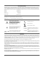


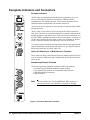

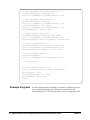


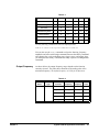
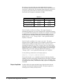
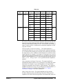
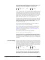

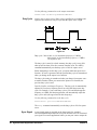
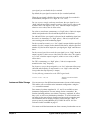
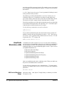
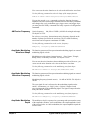
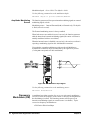
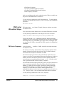
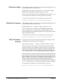
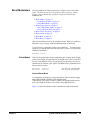

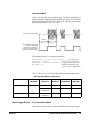
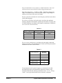
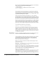


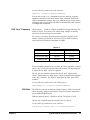

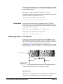

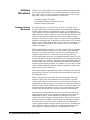


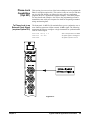
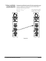
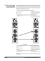

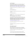
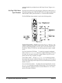
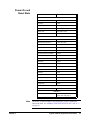


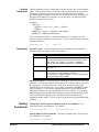

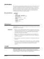


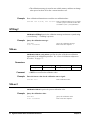
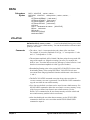

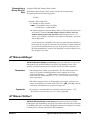


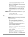


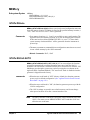

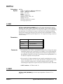

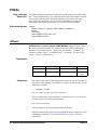
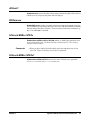
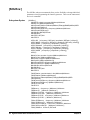


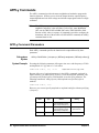


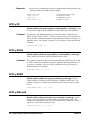

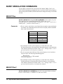
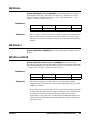
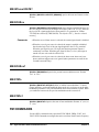
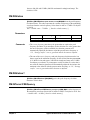
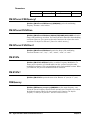

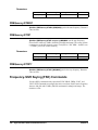
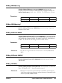
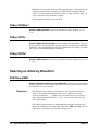
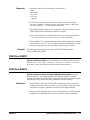
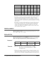
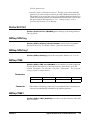

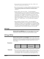


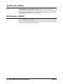
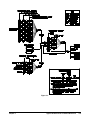


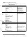
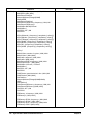
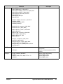


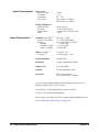
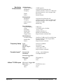
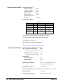
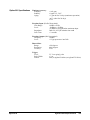


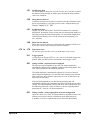


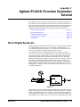

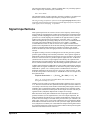
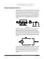


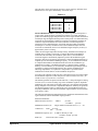

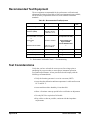
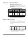
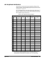


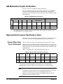
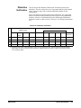

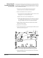


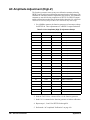

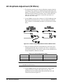
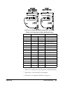
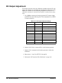

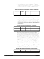
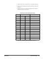
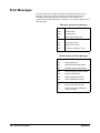
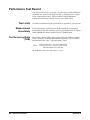
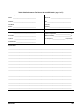


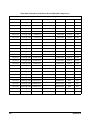
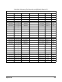

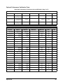


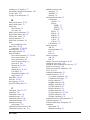

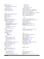


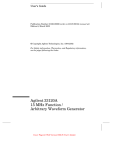

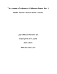
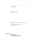
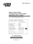

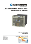


![[SOURce[1|2]]](http://vs1.manualzilla.com/store/data/005803287_1-72ff358839cd16ae2e8c94de56269657-150x150.png)