1
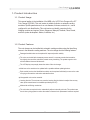
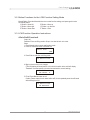
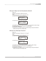
Coin Changer
Installation Guide
Coin Changer
Contents
1. Product Introduction..………………………………………….…….…..3
1-1. Product Usage............................................................................3
1-2. Product Features........................................................................3
1-3. Product Specifications................................................................4
2. Exterior Dimensions..........................................................................5
2-1. Product Dimensions....................................................................5
2-2. Installation Instructions...............................................................6
2-3. Appearance Description..............................................................8
3. LCM Settings...................................................................................10
3-1. Button Functions .......................................................................10
3-2. LCM Function Setting Mode and Button Functions....................11
3-3. LCM Function Operation Instructions.........................................11
4. Wiring ...............................................................................................21
4-1. Wire Diagram .............................................................................21
4-2. Connection to the ICT Bill Machine ...........................................26
4-3. I/O...............................................................................................28
5. Cleaning Diagram ............................................................................30
6. Troubleshooting................................................................................33
6-1. Signal Messages .......................................................................33
7. Program Download...........................................................................47
7-1. MCU STM8 Program Download and Burning User Manual........47
7-2. MCU STM32 Program Download and Burning Instructionl.........51
8. Steps for Disassembling ..................................................................56
8-1. Upper Module Disassembling.....................................................56
8-2. Module Identification and Disassembling...................................58
8-3. Disassembling of the Coin Discharge Module ...........................60
9. Module Exploded Diagram................................................................62
www.ictgroup.com.tw
Coin Changer
Use of Materials Limitations
International Currency Technologies Corporation (ICT) all rights reserved.
All materials contained are the copyrighted property of ICT.
All trademarks, service marks, and trade names are proprietary to ICT.
ICT reserves the right at all times to disclose or to modify any information as
ICT deems necessary to satisfy any applicable law, regulation, legal process
or governmental request, or to edit, refuse to post or to remove any information
or materials, in whole or in part, in ICT's sole discretion.
www.ictgroup.com.tw
Coin Changer
1. Product Introduction
1-1. Product Usage
This manual applies to the installation of the MDB or the VCCS Coin Changer of the ICT
Coin Changer (CC6000). This coin inserter is suitable for kiosks or automatic vending
machines. Specific parameters such as coin diameter, thickness, material, etc., can be
configured for coin identification. This coin inserter can identify currencies for the
following countries and regions: Taiwan, Singapore, Malaysia, Thailand, China, Russia,
and Euro (under development: Mexico, Indonesia, etc.).
1-2. Product Features
The coin changer can be installed into automatic vending machines using the three fixing
screws in the automatic vending machines. The coin changer has the following features:
Damaged modular tubes can be replaced for improved product usability.
The coins can be held at the temporary escrow area. If a consumer cancels the transaction,
the original coins would be returned to prevent money laundering. The system supports coins
with two different sizes and thicknesses.
The LCD display can promptly shows the status of the coin changer.
Machines on the market can be updated with a portable software updating devices.
Each module (such as the identification module) can be replaced individually to save on the costs
of buying a new machine and reduce maintenance time.
Unsupported coins can be canceled.
Learning function: The customer can press the learning function button to readjust the currency
rates (must execute based on standards provided by the ICT).
Mechanical anti-fishing mechanism.
The coin tubes can replenish coins automatically without a standby coin tube. This product uses
the six tube cycling system to reduce the number of manual coin replacement instances required.
3
www.ictgroup.com.tw
Coin Changer
1-3. Product Specifications
Supply Voltage :
MDB 20V DC ~ 45V DC
VCCS:24V DC ± 10%
Power Consumption:
Standby mode
≦ 3.6W
Coin acceptance ≦ 15.6W
Coin payout
≦ 15.6W / Motor
(36W max. when Power is turned on instantly)
Battery operation :
≦ 10uA
Sleep mode
Standby mode
≦ 3.6W(wake-up mode)
Temperature Tange:
-15°C ~ +60°C
Storage Temperature:
-30°C ~ +70°C
Temperaturr Change:
Max. 0.2°C / minute
Relative Humidity:
Up to 85%
Machine Interface:
MDB or VCCS
Coins Acceptance:
Coin diameter 16mm ~ 28mm
Coin Thickness 1.2mm ~ 2.6mm
Coin payout:
Max. 6 coin types from a tube cassette
Coin diameter and thickness depend on tube cassette in use:
TUBE
26.0 - 28.5
A
v,*
B
v,*
C
-
D
-
E
-
F
-
24.0 - 26.0
v,*
v
v
v
v
22.0 - 24.0
v
v
v
v
20.0 - 22.0
v,*
v
v,*
v
v
v
v
v
v
18.0 - 20.0
v
v
v
v
v
v
16.0 - 18.0
v
v
v
v
v
v
Coin Diameter mm
(* Supports Escrow Function)
Acceptable Speed:
Approx. 1 pcs. / second
Device dimensions:
138(W) x 81(D) x 369.6(H) mm
Mounting position:
Vertical, max. deviation: ± 3°
Mark of conformity:
CE
www.ictgroup.com.tw
4
Coin Changer
2. Exterior Dimensions
2-1. Product Dimensions
30.2
Figure.1
64.5
360.2
138
380.2
369.6
114.5
10
68.4
82.5
140.6
45.1
75.8
Unit : mm
5
www.ictgroup.com.tw
Coin Changer
2-2. Installation Instructions (added module marks)
1. Prior to installation, remove the coin inserter from the carton and inspect for damages.
2. Turn off the power of the automatic vending machine.
3. Unhook the green hook at the left side of the coin inserter and tilt the coin identification
and separation module.
Figure.2
4. After the coin identification and separation modules are opened, you can see 3 hanging holes.
Affix the coin inserter through the 3 hanging holes with screws. It would be preferable to secure
all three screws.
Figure.3
5. Tighten the screws and install the coin identification and separation module.
6. Press the green coin tube fixing latch to pull out the money tube apparatus at a upwardly slanted angle.
Figure.4
7. Fill the coins and ensure that the coins enter the corresponding tubes and are flatly placed in the tube.
Then install the coin tubes into the Coin Changer.
8. You can also choose not to open the coin tube module and insert the coins through the tube openings
to automatically refill the coins. (Refer to LCM setting)
www.ictgroup.com.tw
6
Coin Changer
《Installing the Connection》
After the coin inserter has been installed, check and ensure that there is a 3 to 5 mm gap between
the coin return button of the coin inserter and the coin return lever of the automatic vending machine.
Check to ensure that when the coin return lever of the automatic vending machine has been pulled
and released, the flight board of the coin identification module can open and close freely. Check to
ensure that the coin insertion, coin return box, and coin storage box channels of the automatic vending
machine line up with the corresponding channels of the coin inserter. If they do not line up, please
adjust accordingly. Insert a coin to inspect whether the coin can pass through the passage channel
successfully. Please ensure that the opening of the automatic vending machine do not press or push
against the coin identification module.
《Wire Connections》:
Sometimes numerous wires will be connected to the CC6000 for interface communication or statistical
information collection. Please ensure that these wires are connected correctly. After the connections
are confirmed, neatly bundle the unused wires. Please ensure that there are no interferences between
the connected wires, the coin insert and return device, and the door of the automatic vending machine.
After the inspections are complete, please turn on the power of the automatic vending machine.
《Initialization》:(Initial Power Up after Removal from the Box)
Inspect the amount of coins in each coin tube after power up. The coin inserter would not work correctly
without enough coins in the coin tubes. The user must ensure that the amount of coins in each coin tube
exceeds the sticker mark on the coin tubes. After the user has filled the coins, the coin inserter would
detect the adequacy of coin quantity within a few seconds. The user should discharge at least 1 coin from
each coin tube to ensure that the discharged coins fall into the coin return box of the vending machine.
Note: At this point, the coin inserter can operate properly.
7
www.ictgroup.com.tw
Coin Changer
2-3. Appearance Description
《Identification》:As shown in figure below
Figure.5
Coin Return Button
Hook
《Coin Return Button》:After a coin is inserted, press the coin return button to return the coin
《LCM Panel》:As shown in figure below
Figure.6
Power Indicator
LCM
Error Indicator
Latch
7 Panel Buttoms
Download Outlet
The latch used to open the LCM panel, as shown in figure below
Figure.7
www.ictgroup.com.tw
8
Coin Changer
《Coin Tubes》:Press the latch as shown to withdrawn coins
Figure.8
Latch
A
F
E
C
D
B
《DIP Description》:
Figure.9
DIP SW1: Set to OFF for high acceptance (1st Currency)
Set to ON for high anti-counterfeiting (1st Currency)
DIP SW2: Set to OFF for high acceptance (2nd Currency)
Set to ON for high anti-counterfeiting (2nd Currency)
DIP SW3: Set to OFF for high acceptance (3rd Currency)
Set to ON for high anti-counterfeiting (3rd Currency)
DIP SW4: Set to OFF for high acceptance (4th Currency)
Set to ON for high anti-counterfeiting (4th Currency)
DIP SW5: Preset to OFF
DIP SW6: Preset to OFF
DIP SW7: Preset to OFF
DIP SW8: Set to ON to turn off the sleep mode
Set to OFF to turn on the sleep mode
Note: Only the Power Saving-MDB product has the DIP SW8 function
9
www.ictgroup.com.tw
Coin Changer
3. LCM Settings
3-1. Button Functions
Figure.10
Manual Button:
Normal Mode: Press 1 to enter the LCM setting page. Press the Coin Return and the Manual buttons
together for 3 seconds to set the minimum coin number for all of the coin tubes. If the minimum coin
number is not set by the user, the default minimum coin number would be used.
LCM Mode: Press 1 to return to the previous page.
“A” Button:
Normal Mode: Press once and the “A” tube would discharge 1 coin. Press the Coin Return and the
“A” buttons together for 3 seconds and the “A” tube would discharge coins until it hit the low level and
become emptied.
LCM Mode: Press “A” for page switching.
“B” Button:
Normal Mode: Press once and the “B” tube would discharge 1 coin. Press the Coin Return and the
“B” buttons together for 3 seconds and the “B” tube would discharge coins until it hit the low level and
become emptied.
LCM Mode: Press "B” to set the accumulation value.
“C” Button:
Normal Mode: Press once and the “C” tube would discharge 1 coin. Press Coin Return and the
“C” buttons together for 3 seconds and the “C” tube would discharge coins until it hit the low level and
become emptied.
LCM Mode: Press “C” to switch pages or set parameters (add).
“D” Button:
Normal Mode: Press once and the “D” tube would discharge 1 coin. Press the Coin Return and the
“D” buttons together for 3 seconds and the “D” tube would discharge coins until it hit the low level
and become emptied.
“E” Button:
Normal Mode: Press once and the “E” tube would discharge 1 coin. Press the Coin Return and the
“E” buttons together for 3 seconds and the “E” tube would discharge coins until it hit the low level and
become emptied.
LCM Mode: Press “E” to switch pages or set parameters (subtract).
“F” Button:
Normal Mode: Press once and the “E” tube would discharge 1 coin. Press the Coin Return and the
“E” buttons together for 3 seconds and the “E” tube would discharge coins until it hit the low level and
become emptied.
LCM Mode: Press “F” to confirm.
www.ictgroup.com.tw
10
Coin Changer
3-2. Button Functions for the LCM Function Setting Mode
Manual Button: Press the Manual button once to enter function settings, and press again to enter
the standby status.
“A” Button = Move left
“B” Button = Move up
“C” Button = Move right
“D” Button = no function
“E” Button = Move down
“F” Button = Enter
3-3. LCM Function Operation Instructions.
«Coin Refill Function»
Code: 100
Definition: Enter coin filling mode to fill up to Low level of each coin value.
Steps:
1. Press Manual button to enter configuration mode.
2. Press A/C button and scroll to EZ code 100.
Refill Coin
100
3. Press Enter to enter the coin filling mode.
Pls Refill Coin
4. Begin to insert coins to coin changer.
(The LCM display will show how the coin to store into which tube, and it will display
“Reached!” once that specific coin value has reached its Low level setting.)
Pls Refill Coin
10-TubeB: 6
5. Finish! Press Manual button to exit.
Caution: Please empty the coin tubes before refill, do not repeatedly enter the refill mode
while refilling the coins.
Pls Refill Coin
10 Reached!
11
www.ictgroup.com.tw
Coin Changer
«Check the Total Coin “PayIn” and “PayOut” Value Differences»
Code: 101
Definition: Display Current Bookkeeping data.
Steps:
1. Press Manual button to enter configuration mode.
2. Press A/C button and scroll to EZ code 101.
Total In/Out
101
3. Press Enter to the total amount display.
PayIn :
PayOut :
$0
$0
4. Press B/E bottom to display Pay in amount, Pay out amount, and difference.
( IN>OUT display “+”, OUT>IN display “-”)
Difference:
$0
+
5. Press Manual button to exit.
6. Press the “A” or “C” button to select other function settings, and press the “Manual”
button to return back to the standby mode.
«Clear all PayIn and PayOut Records»
Code: 102
Definition: Reset bookkeeping data.
Steps:
1. Press Manual button to enter configuration mode.
2. Press A/C button and scroll to EZ code 102.
Reset Records
102
3. Press Enter to reset the memory database.
Check Current
Are You Sure?
4. The changer will display message once data has been erased successfully,
and go back to main configuration screen.
Data has been
erased
5. Press the “A” or “C” button to select other function settings, and press the
“Manual” button to return back to the standby mode. PayIn/PayOut record
deletion requires additional confirmation (refer to 113)
www.ictgroup.com.tw
12
Coin Changer
«Accept or Reject the Coin Denomination Switch»
Code: 103
Definition: On/off switch for different Coin Value.
Steps:
1. Press Manual button to enter configuration mode.
2. Press A/C button and scroll to EZ code 103.
Accept/Reject
Coin Switch 103
3. Press Enter to enter coin value select mode.
TWD $1 : Accept
Enter to Change
4. Press B/E button to scroll up/down to select the coin value desired to make a change.
5. Press Enter to change its current setting. (On Off/Off On)
6. Press Manual button to exit.
7. Press the “A” or “C” button to select other function settings, and press the “Manual”
button to return back to the standby mode.
«Set the Coin Tube Open Function»
Code: 104
Definition: On/off switch for Tube A, B, C, D, E, and F.
Steps:
1. Press Manual button to enter configuration mode.
2. Press A/C button and scroll to EZ code 104.
Tube Open/Close
Switch
104
3. Press Enter to enter tube select mode.
TUBE A
ON
Enter to Change
4. Press B/E button to scroll up/down to select tube desired to make a change.
5. Press Enter to change its current setting. (On Off/Off On)
6. Press Manual button to exit.
7. Press the “A” or “C” button to select other function settings, and press the “Manual”
button to return back to the standby mode.
13
www.ictgroup.com.tw
Coin Changer
«Set the Bill Acceptance Count for the BA»
Special Function
Code: 106
Definition: Configure number of bills accepted per transaction.
(Only work on ICT Bill Acceptor connect to Coin Changer)
Note: This is a special function. The Coin Changer must be equipped with the ICT
Bill Acceptor for this function to work.
Steps:
1. Press Manual button to enter configuration mode.
2. Press A/C button and scroll to EZ code 106.
Bill(s) per
Transaction 106
3. Press Enter to number configuration mode.
Bill
Counts
8
PCS
4. Press B/E button to scroll up/down to change to number desired. (Default: 1)
The page below would appear after each save. If this page does not appear,
that means the settings were not saved, and please reconfirm and press the
“Enter” button to save the settings.
Saved
5. Press Manual button to exit.
6. Press the “A” or “C” button to select other function settings, and press the
“Manual” button to return back to the standby mode.
www.ictgroup.com.tw
14
Coin Changer
«Set the Maximum Coin Stock Value for the Various Coin Denominations»
Code: 107
Definition: Configure High Level quantity of each coin value.
Factory Default: 250
Available Configure Range: 33~250
Steps:
1. Press Manual button to enter configuration mode.
2. Press A/C button and scroll to EZ code 107.
Setup High
Q'TY
107
3. Press Enter to enter coin value select mode.
TWD $ 1
High Level : 250
4. Press B/E button to scroll up/down to select the coin value desired to make a change.
5. Press Enter to enter adjust mode.
Change
250
Set
Q'TY
6. Press B/E button to scroll up/down to adjust the number of High Level desired.
※The page below would appear after each save. If this page does not appear,
that means the settings were not saved, and please reconfirm and press the
“Enter” button to save the settings.
Saved
7. Press Manual button to save its configuration. The display will go back to coin value
select mode after the configuration has been saved successfully.
8. Press the “A” or “C” button to select other function settings, and press the “Manual”
button to return back to the standby mode.
15
www.ictgroup.com.tw
Coin Changer
«Set the Maximum Coin Refill Number and Remaining Coin Stock to
Remain after Automatic Clearing»
Code: 108
Definition: Configure Low Level quantity of each coin value.
Note: The default factory value is based on the lowest coin stock standard for the various
countries' currencies.
Steps:
1. Press Manual button to enter configuration mode.
2. Press A/C button and scroll to EZ code 108.
Setup
Low
Q'TY
108
3. Press Enter to enter coin value select mode.
TWD
Low
$ 1
Level : 14
4. Press B/E button to scroll up/down to select the coin value desired to change.
5. Press Enter to enter adjust mode.
Change Set
14
Q'TY
6. Press B/E button to scroll up/down to adjust the number of Low Level desired.
※The page below would appear after each save. If this page does not appear,
that means the settings were not saved. Please reconfirm and press the “Enter”
button to save the settings.
Saved
7. Press Manual button to save its configuration. The display will go back to coin
value select mode after the configuration has been saved successfully.
8. Press the “A” or “C” button to select other function settings, and press the “Manual”
button to return back to the standby mode.
www.ictgroup.com.tw
16
Coin Changer
«Check the Maximum and Minimum Coin Stock Level Settings»
Code: 109
Definition: Request current setting saved inside coin changer's memory.
Steps:
1. Press Manual button to enter configuration mode.
2. Press A/C button and scroll to EZ code 109.
Check Current
Hi/Low Q'TY 109
3. Press Enter to enter information acquiring mode.
$ 1 High : 250
$ 1 Low : 14
4. Press B/E button to scroll up/down to different coin value's Hi/Low tube level configuration.
5. Press Manual button to exit.
6. Press the “A” or “C” button to select other function settings, and press the “Manual”
button to return back to the standby mode.
«Set the Change Return Mode»
Code: 110
Definition: Return the original coin value / Return from the largest coin value.
Note: This function only works with the VCCS interface
Steps:
1. Press Manual button to enter configuration mode.
2. Press A/C button and scroll to EZ code 110.
Change
Mgmt.
110
3. Press Enter to coin management setting mode.
Large Coins
Enter to Change
4. Press Enter to change its current setting.
(Large Coins/Org. Coin Value)
5. Press Manual button to exit.
6. Press the “A” or “C” button to select other function settings, and press the “Manual”
button to return back to the standby mode.
17
www.ictgroup.com.tw
Coin Changer
«Set the Standby LCM Display Mode»
Code: 111
Definition: Change coin changer's display when idle.
Steps:
1. Press Manual button to enter configuration mode.
2. Press A/C button and scroll to EZ code 111.
Display Method
111
3. Press Enter to display method configuration mode.
Q'TY of Tube
Enter to Change
4. Press Enter to change its display method.
(Q'TY of Tube/Total Coin Value)
5. Press Manual button to exit.
6. Press the “A” or “C” button to select other function settings, and press the “Manual”
button to return back to the standby mode.
«Set the BA Interface»
Special Function
Code: 112
Definition: Select type of BA connected.
(Only work on ICT Bill Acceptor connect to Coin Changer)
Note: This is a special function. The Coin Changer must lap joint with the ICT Bill
Acceptor for this function to work.
Steps:
1. Press Manual button to enter configuration mode.
2. Press A/C button and scroll to EZ code 112.
BA Type Setting
112
3. Press Enter to select BA Type.
BA: VCCS
Enter to Change
4. Press Enter to change its setting. (VCCS/MDB)
5. Press Manual button to exit.
6. Press the “A” or “C” button to select other function settings, and press the
“Manual” button to return back to the standby mode.
www.ictgroup.com.tw
18
Coin Changer
«Restore the Default Factory Settings»
Code: 113
Definition: Restore factory default setting. Example: Hi/Low Level Qty of each tube…etc
Steps:
1. Press Manual button to enter configuration mode.
2. Press A/C button and scroll to EZ code 113.
Default Setting
113
3. Press Enter to restore factory setting mode.
Default Setting
Are You Sure?
4. Press Enter to confirm go back to factory default.
5. Press Manual button to exit.
6. Press the “A” or “C” button to select other function settings, and press the
“Manual” button to return back to the standby mode.
«Set the Memory Function for the Coin Tubes»
Code: 114
Definition: ON Coin changer will memorize its quantity of each tube.
OFF Coin changer will not memorize its quantity of each tube. (Default)
Steps:
1. Press Manual button to enter configuration mode.
2. Press A/C button and scroll to EZ code 114.
Tube Memory
114
3. Press Enter to configure tube memory mode.
Memory: Disable
Enter to Change
4. Press Enter to change its current setting. (On Off/Off On)
5. Press Manual button to exit.
6. Press the “A” or “C” button to select other function settings, and press the
“Manual” button to return back to the standby mode.
19
www.ictgroup.com.tw
Coin Changer
«Clear All Memory for the Coin Tubes»
Special Function
Code: 115
Definition: Clear Tube Memory in Display when Tube Memory ON
Note: This is a special function. The Coin Changer must be equipped with the
memory mode for this function to work.
Steps:
1. Press Manual button to enter configuration mode.
2. Press A/C button and scroll to EZ code 115.
Clear Tube Count
115
3. Press Enter to reset the memory database.
Clear Tube Count
Are You Sure?
4. The changer will display message once data has been erased successfully,
and go back to main configuration screen.
Clear Tube Count
Clear Finish
5. Press the “A” or “C” button to select other function settings, and press the “Manual”
button to return back to the standby mode.
«Coin Tube Configuration Mode»
Special Function-Singapore Product Specific
Code: 116
Definition: Configure the tube coin assignment without change the firmware
Steps:
1. Press Manual button to enter configuration mode.
2. Press A/C button and scroll to EZ code 116.
Tube Setup
116
3. Press Enter to configure different tube assignment.
4. Press Enter to change between different selections.
(Please ask your sales for the tube assignment availability.)
TUBE: Mode1
Enter to Change
TUBE: Mode2
Enter to Change
5. Press Manual button to exit.
6. Press the “A” or “C” button to select other function settings, and press the
“Manual” button to return back to the standby mode.
www.ictgroup.com.tw
20
Coin Changer
4. Wiring
4-1. Wire Diagram:
Harness
Page
Interface
Used Voltage
Usage
VCCS
24V DC
Power & *Data Comm.
WEL-RCC24-T
9
VCCS
24V DC
Power & *Data Comm.
WEL-RCC50-T
10
VCCS
24V DC
Power & *Data Comm.
WEL-RCC49-T
11
MDB
24V DC
Power & *Data Comm.
WEL-RCC23-T
12
MDB
24V DC
Power & *Data Comm.
WEL-RCC51-T
13
MDB
24V DC
Power & *Data Comm.
WEL-RCC47-T
14
Figure.11
Interface
Used Voltage
VCCS
24V DC
Usage
Power & *Data Comm.
5
4
3
2
1
2464 80 C 300V 22AWG 5C CABLE
PH-A5(2.0mm)
#WEL-RCC24
5. RED
4. ORANGE
3. GREEN
2. BLUE
1. YELLOW
CC6000 VCCS
WEL-RCC24-T
1
2
3
4
5
6
7
8
1. RED
4. GREEN
5. YELLOW
6. BLUE
8. ORANGE
JST XLR-08V
PIN
PIN
PIN
PIN
PIN
5- RED........... .................+24VDC
4- PURPLE........................... GND
3- GREEN............... VCCS_SYNC
2- BLUE................... ....VCCS_RX
1- YELLOW.................. VCCS_TX
4
3
2
1
8
7
6
5
JST XLR-08V BACK VIEW
PIN 1- RED..... ...................+24VDC
PIN 4- GREEN........ ...VCCS_SYNC
PIN 5- YELLOW............ ..VCCS_TX
PIN 6- BLUE................. ..VCCS_RX
PIN 8- ORANGE......................GND
Length: 55cm
21
www.ictgroup.com.tw
Coin Changer
Figure.12
Interface
Used Voltage
VCCS
24V DC
Usage
Power & *Data Comm.
5
4
3
2
1
2464 80 C 300V 22AWG 5C CABLE
PH-A5(2.0mm)
PIN
PIN
PIN
PIN
PIN
5- RED........... .................+24VDC
4- PURPLE........................... GND
3- GREEN............... VCCS_SYNC
2- BLUE................... ....VCCS_RX
1- YELLOW.................. VCCS_TX
1
2
3
4
5
6
7
8
#WEL-RCC50
5. RED
4. ORANGE
3. GREEN
2. BLUE
1. YELLOW
CC6000 VCCS
WEL-RCC50-T
4
3
2
1
8
7
6
5
JST XLR-08V BACK VIEW
1. RED
4. GREEN
5. YELLOW
6. BLUE
8. ORANGE
PIN 1- RED..... ...................+24VDC
PIN 4- GREEN........ ...VCCS_SYNC
PIN 5- YELLOW............ ..VCCS_TX
PIN 6- BLUE................. ..VCCS_RX
PIN 8- ORANGE......................GND
Length: 75cm
Figure.13
Interface
Used Voltage
VCCS
24V DC
Usage
Power & *Data Comm.
5
4
3
2
1
2464 80 C 300V 22AWG 5C CABLE
PH-A5(2.0mm)
PIN
PIN
PIN
PIN
PIN
#WEL-RCC49
5. RED
4. ORANGE
3. GREEN
2. BLUE
1. YELLOW
CC6000 VCCS
WEL-RCC49-T
5- RED........... .................+24VDC
4- PURPLE........................... GND
3- GREEN............... VCCS_SYNC
2- BLUE................... ....VCCS_RX
1- YELLOW.................. VCCS_TX
4
3
2
1
8
7
6
5
JST XLR-08V BACK VIEW
Length: 95cm
www.ictgroup.com.tw
22
1
2
3
4
5
6
7
8
1. RED
4. GREEN
5. YELLOW
6. BLUE
8. ORANGE
PIN 1- RED..... ...................+24VDC
PIN 4- GREEN........ ...VCCS_SYNC
PIN 5- YELLOW............ ..VCCS_TX
PIN 6- BLUE................. ..VCCS_RX
PIN 8- ORANGE......................GND
Coin Changer
Figure.14
Interface
Used Voltage
MDB
24V DC
Usage
Power & *Data Comm.
PH-A6(2.0mm)
PIN
PIN
PIN
PIN
PIN
PIN
123456-
BLUE......... .................+34VDC
YELLOW......................... .GND
PURPLE......... MDB_WAKEUP
BROWN.................... MDB_RX
RED.................. ......... MDB_TX
GREEN............. .....MDB_GND
6
5
4
3
2
1
1
2
3
4
5
6
#WEL-RCC23
2464 80 C 300V 22AWG 6C CABLE
CC6000 MDB
WEL-RCC23-T
1
2
3
4
5
6
#NAME?
MOLEX 5557-6R BACK VIEW
PIN 1PIN 2PIN 3PIN 4PIN 5PIN 6-
1. BLUE
2. YELLOW
3. PURPLE
4. BROWN
5. RED
6. GREEN
BLUE... ...................+34VDC
YELLOW..... .................GND
PURPLE..... MDB_WAKEUP
BROWN................MDB_RX
RED......................MDB_TX
GREEN..............MDB_GND
Length: 57cm
Figure.15
Interface
Used Voltage
MDB
24V DC
Usage
Power & *Data Comm.
PH-A6(2.0mm)
PIN
PIN
PIN
PIN
PIN
PIN
123456-
BLUE......... .................+34VDC
YELLOW......................... .GND
PURPLE......... MDB_WAKEUP
BROWN.................... MDB_RX
RED.................. ......... MDB_TX
GREEN............. .....MDB_GND
6
5
4
3
2
1
1
2
3
4
5
6
#WEL-RCC51
2464 80 C 300V 22AWG 6C CABLE
CC6000 MDB
WEL-RCC51-T
1
2
3
4
5
6
#NAME?
MOLEX 5557-6R BACK VIEW
PIN 1PIN 2PIN 3PIN 4PIN 5PIN 6-
1. BLUE
2. YELLOW
3. PURPLE
4. BROWN
5. RED
6. GREEN
BLUE... ...................+34VDC
YELLOW..... .................GND
PURPLE..... MDB_WAKEUP
BROWN................MDB_RX
RED......................MDB_TX
GREEN..............MDB_GND
Length: 77cm
23
www.ictgroup.com.tw
Coin Changer
Figure.16
Interface
Used Voltage
MDB
24V DC
Usage
Power & *Data Comm.
PH-A6(2.0mm)
6
5
4
3
2
1
#NAME?
MOLEX 5557-6R BACK VIEW
4
5
6
1
2
3
MOLEX 5559-06P BACK VIEW
PIN 1PIN 2PIN 3PIN 4PIN 5PIN 6PIN 1PIN 2PIN 3PIN 4PIN 5PIN 6-
1
2
3
4
5
6
#WEL-RCC47
2464 80 C 300V 22AWG 6C CABLE
CC6000 MDB
WEL-RCC47-T
1
2
3
4
5
6
MOLEX 5557-6R
BLUE... ...................+34VDC
YELLOW..... .................GND
PURPLE..... MDB_WAKEUP
BROWN................MDB_RX
RED......................MDB_TX
GREEN..............MDB_GND
BLUE... ...................+34VDC
YELLOW..... .................GND
PURPLE..... MDB_WAKEUP
BROWN................MDB_RX
RED......................MDB_TX
GREEN..............MDB_GND
1. BLUE
2. YELLOW
3. PURPLE
4. BROWN
5. RED
6. GREEN
1
2
3
4
5
6
1. BLUE
2. YELLOW
3. PURPLE
4. BROWN
5. RED
6. GREEN
MOLEX 5559-06P
PIN
PIN
PIN
PIN
PIN
PIN
123456-
BLUE......... .................+34VDC
YELLOW......................... .GND
PURPLE......... MDB_WAKEUP
BROWN.................... MDB_RX
RED.................. ......... MDB_TX
GREEN............. .....MDB_GND
Length: 97cm
Figure.17
WEL-RCC31-T
4
3
2
1
PIN 1PIN 2PIN 3PIN 4-
RED... ..............+24VDC
BLACK..... ..............GND
YELLOW........ NV72_TX
WHITE.............V72_RX
MOLEX 5557-4R BACK VIEW
1
2
3
4
5
6
7
8
PIN 1- RED... ...........+24VDC
PIN 8- BLACK..... ...........GND
JST XLP-08V BACK VIEW
MOLEX 5557-4R
1
2
3
4
1
2
3
4
5
6
7
8
CC6000 for NV72-1
#WEL-RCC31
1
2
3
4
JST XLP-08V
MOLEX 5559-04P
3
4
1
2
PIN 1PIN 2PIN 3PIN 4-
RED... ....................+24VDC
BLACK..... ....................GND
YELLOW.......... .... NV72_TX
WHITE.................NV72_RX
MOLEX 5559-04P BACK VIEW
2
1
MOLEX 5557-2R
2
1
PIN 1- YELLOW.......NV72_RX
PIN 2- WHITE..........NV72_TX
MOLEX 5557-2R BACK VIEW
www.ictgroup.com.tw
24
Coin Changer
Figure.18
WEL-RCC32-T
4
3
2
1
PIN 1- RED... ..............+24VDC
PIN 2- BLACK..... ..............GND
PIN 3- YELLOW........ NV72_TX
PIN 4- WHITE.............V72_RX
2464 80 C 300V 22AWG 4C CABLE
PH-A4(2.0mm)
1
2
3
4
#WEL-RCC32
1
2
3
4
CC6000 for NV72
MOLEX 5557-4R BACK VIEW
MOLEX 5557-4R
1
2
3
4
PIN 1- RED.................+24VDC
PIN 2- BLACK..................GND
PIN 3- YELLOW........NV72_TX
PIN 4- WHITE..........NV72_RX
MOLEX 5559-04P
3
4
1
2
PIN 1- RED... ....................+24VDC
PIN 2- BLACK..... ...................GND
PIN 3- YELLOW.......... .... NV72_TX
PIN 4- WHITE.................NV72_RX
MOLEX 5559-04P BACK VIEW
Figure.19
1
3
2
4
PIN 1- BLACK..........GND
PIN 2- YELLOW........RX2
PIN 3- GREEN..........TX2
WEL-RCC42-T
JST ELP-04NV BACK VIEW
1
2
3
4
1. BLACK
2. YELLOW
3. GREEN
JST ELP-04NV
1. BLACK
2. RED
3. GRAY
4. ORANGE
5. BROWN
6. BLUE
1
2
3
4
5
6
2464 26AWG 8C CABLE BLACK
TMT 2*3
8
7
6
5
4
3
2
1
TMT 2*4
PIN 1- BLACK..................GND
PIN 2- RED.......................VCC
PIN 3- GRAY................RESET
PIN 4- ORANGE....PROGRAM
TMT 2*3 BACK VIEW PIN 5- BROWN.................RX1
PIN 6- BLUE......................TX1
2 4 6
1 3 5
2 4 6 8
1 3 5 7
TMT 2*4 BACK VIEW
25
PIN 1- BLACK.......................GND
PIN 2- GREEN.......................TX2
PIN 3- YELLOW....................RX2
PIN 4- ORANGE........PROGRAM
PIN 5- GRAY....................RESET
PIN 6- RED...........................VCC
PIN 7- BLUE..........................TX1
PIN 8- BROWN.....................RX1
www.ictgroup.com.tw
Coin Changer
4-2. Connecting the ICT Bill Acceptor:
4-2-1. Wiring:
Figure.20
WEL-RCC46-T
1
2
3
4
5
6
CC6000 BA2
#WEL-RCC46
8
7
6
5
4
3
2
1
JST XLR-08V
MOLEX 5559-06P
2
1
MOLEX 5559-02P
4
3
2
1
8
7
6
5
PIN 1- BLUE....................+24VDC
PIN 2- YELLOW+GREEN......GND
JST XLR 08V BACK VIEW
2
1
MOLEX 5559-02P BLACK VIEW
PIN 1- RED......................NV72_RX
PIN 2- ORANGE..............NV72_TX
4
5
6
1
2
3
MOLEX 5559-06P BACK VIEW
PIN 1PIN 2PIN 4PIN 5PIN 6-
BLUE... ...................+24VDC
YELLOW..... .................GND
ORANGE..............NV72_TX
RED......................NV72_RX
GREEN..............MDB_GND
Figure.21
WEL-RCC48-T
1
2
3
4
5
6
7
8
JST XLP-08V BACK VIEW
1
2
3
4
2464 80
300V 22AWG 4C CABLE
PH-A4(2.0mm)
#WEL-RCC48
1.RED
2. BLACK
VCCS_TX 3. YELLOW
VCCS_RX 4.WHITE
CC6000 for NV72
+24V
P_GND
1
2
3
4
5
6
7
8
1. RED
8. BLACK
JST XLP-08V
2
6mm±2mm
100mm ±5mm
NV77_TX
2.WHITE
1. YELLOW NV77_RX
1
75mm ±5mm
MOLEX 5557-2R
810mm(10mm ± 5mm)
40mm ±5mm
950mm ±10mm
www.ictgroup.com.tw
+24V
P_GND
26
2
1
MOLEX 5557-2R BACK VIEW
Coin Changer
Figure.22
WEL-RCC67-T
4
5
6
1
2
3
1.RED
2. BLACK
1
2
3
4
2464 80
300V 22AWG 4C CABLE
PH-A4(2.0mm)
1. RED
2. BLACK
4. WHITE
5. YELLOW
6. GREEN
MOLEX 5559-06P
75mm ±5mm
6mm ±2mm
100mm ±5mm
1
2
3
4
5
6
ICT MDB_BA ONLY
+24V
P_GND
VCCS_TX 3. YELLOW
VCCS_RX 4.WHITE
#WEL-RCC64
#NAME?
MOLEX 5559-06P BACK VIEW
800mm(10mm 5mm)
40mm ±5mm
940mm ±10mm
4-2-2. Cautionary Items:
The VCCS Interface Bill Acceptor: NV Series
Wires used: WEL-RCC48
The MDB Interface Bill Acceptor: V Series、TAO-V、V7E、S7A…
Wires used: WEL-RCC67
or WEL-RCC46 + WEL-RCC48
Please reference code 112 for the setting function
27
www.ictgroup.com.tw
Coin Changer
4-3. I/O:
VCCS Interface.
Figure.23
+24VDC
D1
1
2
3
GND
R1
VCCS_TX
Q1
G
D
S
GND
+24VDC
D2
1
2
R2
3
GND
Customer
Side
VCCS_SYNC
SYNC
D4
BZV55-C6V2(6V)
+24VDC
D3
1
GND
2
3
R3
VCCS_RX
RXD
D5
BZV55-C6V2(6V)
www.ictgroup.com.tw
28
TXD
Coin Changer
MDB Interface.
Figure.24
+5V~+12V
+5VDC
VCC
R
1K
D
Hi TR ON
Q
MDB_RXD
Lo TR OFF
R
MDB_TXD
G
R
Q
D
D
R
S
RX22
GND
GND
Customer Side
+5VDC
+5V~+12V
VCC
R
R
1K
Q
R
MDB_TXD
MDB_RXD
GND
G
TX22
D
D
S
GND
Customer Side
29
www.ictgroup.com.tw
Coin Changer
5. Cleaning Diagram
To ensure that the CC6000 Coin Changer can operate properly,
please clean the following materials and parts periodically.
Clean the dust-proof sheet
Figure.25
Clean the dust-proof sheet
Figure.26
www.ictgroup.com.tw
30
Coin Changer
Clean the prism
Figure.27
Figure.28
Clean this side
31
www.ictgroup.com.tw
Coin Changer
Figure.29
Clean this side
Maintenance Notice
(Any improper maintenance will invalidate warranty.)
Alcohol
www.ictgroup.com.tw
Recommended
Mild, non-abrasive, soap water.
DO NOT USE
Organic solvent , Alcohol, Volatility liquid.
32
Coin Changer
6. Troubleshooting
6-1. Signal Messages
«LCM Panel Open»
Code: E10
LED Light Display: 5 red+ 2 red
LCM Display: As shown in figure
Sorting Module
Door Open
E10
Cause: LCM Panel Open
Figure.30
Corrective Measure: Close the LCM panel and verify that the latch is in place.
Figure.31
«Checksum Error»
Code: E11
LED Light Display: Red light
LCM Display: As shown in figure below
Check Sum Error
E11
Cause: Check Sum Error.
Corrective Measure: Notify the ICT personnel
33
www.ictgroup.com.tw
Coin Changer
«Payout Mode Error»
Code: E12
LED Light Indicator: Red light
LCM Display: As shown in figure below
Payout Mode Err
E12
Cause: Signal from the coin base was not received when the power was turned on.
Corrective Method: Ensure that the signal wire is connected to the coin base
Figure.32
«CommunicationErr»
Code: E13
LED Light Display: 1 red
LCM Display: As shown in figure
No Communication
with VMC
E13
Cause: 1. Two seconds after activation, the SYSTEM did not wait for the READY signal
from the DEVICE and jumped to the exception.
2. Two seconds after a transaction, the SYSTEM did not wait for the READY signal
triggered by the DEVICE.
Corrective Measure: 1. Ensure that the machine interface and the VMC interface are consistent.
2. Ensure that the interface transmission wire is properly connected.
Figure.33
www.ictgroup.com.tw
34
Coin Changer
«#1 Coil ERR»
Code: E14
LED Light Display: 3 red+ 1 red
LCM Display: As shown in figure below
Coil Error #1
E14
Cause: Coil 1 is damaged.
Corrective Measure: Notify the ICT personnel
«#2 Coil ERR»
Code: E15
LED Light Display: 3 red + 2 red
LCM Display: As shown in figure below
Coil Error #2
E15
Cause: Coil 2 is damaged.
Corrective Measure: Notify the ICT personnel
«#3 Coil ERR»
Code: E16
LED Light Display: 3 red + 3 red
LCM Display: As shown in figure below
Coil Error #3
E16
Cause: Coil 3 is damaged.
Corrective Measure: Notify the ICT personnel
35
www.ictgroup.com.tw
Coin Changer
«LowLevel LED ERR»
Code: E17
LED Light Display: 3 red+ 5 red
LCM Display: As shown in figure below
Tube Detection
Sensor Error E17
Cause: Low level LED is damaged.
Corrective Measure: Automatically retry once a minute and stop after 10 retries if the
problem is not resolved.
«SortSensor ERROR»
Code: E18
LED Light Display: 3 red + 4 red
LCM Display: As shown in figure below
Sorting Module
Sensor Error E18
Cause: Coin separator sensor problem.
Corrective Measure: 1. Make sure that the reflective prism is not dirty or blocked by
foreign objects. If it is, remove the foreign object and clean the
reflective prism.
2. Retry once a minute for 10 times, if the problem is not resolved,
stop retrying.
Figure.34
www.ictgroup.com.tw
36
Coin Changer
«Deckopen Problem»
Code: E19
LED Light Display: 5 red +1 red
LCM Display: As shown in figure below
Coin Validator
Door Error
E19
Cause:
The deck is open for over 30 seconds.
Figure.35
Corrective Measure: 1. Close the deck and reactive the power.
2. Retry once a minute for 10 times, if the problem is not resolved
then remove the LCM panel to leave this exception.
Figure.36
«MOTOR Problem:A&B»
Code: E20
LED Light Display: 7 red
LCM Display: As shown in figure below
All Motor Error
E20
Cause: Both the first and second group motors cannot be positioned.
Corrective Measure: Please reference instructions for “E19” and “E20” below.
37
www.ictgroup.com.tw
Coin Changer
«MOTOR Problem:A»
Code: E21
LED Light Display: None
LCM Display: As shown in figure below
Left Motor Error
E21
Cause: The first motor group cannot be positioned. The first motor group might be
damaged, coin or foreign objects might have caused the motor to stuck, coins
are stuck in the coin tube, or the semicircle disk has derailed.
Figure.37
Corrective Measure: 1. Confirm whether a foreign object has caused the semicircle disk
to get stuck. If there is, remove the object and turn on the power again.
Use buttons “A” and “B” of the LCM to test and determine whether the
semicircle disk can be returned to its normal position. If it does, then the
machine has returned to normal operation.
Figure.38
2. Verify whether the semicircle disk has derailed. If it has, then move the
disk back onto the track and reactive the machine. Use buttons “A” and
“B” of the LCM to test and determine whether the semicircle disk can be
returned to its normal position. If it does, then the machine has returned to
normal operation.
Figure.39
www.ictgroup.com.tw
38
Coin Changer
«MOTOR Problem:A»
3. Turn on the power again and use buttons “A” and “B” of the LCM to
test and determine whether the semicircle disk can be returned to its
normal position. If it does, then the machine has returned to normal
operation. If nothing happens, then the first motor group has been
damaged. Please notify the ICT personnel to handle the problem.
4. Verify whether the openings of the “A” and “B” tube has been stuck
by a coin. If a tube has been stuck, remove the stuck coin, reassemble
the coin tube, and turn on the power again. Use buttons “A” and “B” of the
LCM to test whether tubes “A” and “B” can discharge coins correctly. If it
does, then the machine has returned to normal operation.
Figure.40
«MOTOR Problem:B»
Code: E22
LED Light Display: None
LCM Display: As shown in figure
Right Motor
Error
E22
Cause: The second motor group cannot be positioned. The second motor group might
be damaged, coin or foreign objects might have caused the motor to stuck, coins
are stuck in the coin tube, or the semicircle disk has derailed.
Figure.41
Corrective Measure: 1. Confirm whether a foreign object has caused an obstruction. If there is,
remove the object and turn on the power again and determine if the coin
rod can return back to its position. Use buttons “C,” “D,” “E,” and “F” of the
LCM to test and determine whether the coin rod can hit the coin correctly.
If it does, then the machine has returned to normal operation.
39
www.ictgroup.com.tw
Coin Changer
2. Turn on the power again to observe whether the disk has repositioned
itself. If it does not, then the second motor group is damaged. Please
notify the ICT personnel to handle the situation.
3. Confirm whether the coin rod is stuck. If it is then manually move the rod
back to its position. Turn on the power again and use buttons “C,” “D,” “E,”
and “F” of the LCM to test whether the coin rod can hit the coin correctly.
If it does, then the machine has returned to normal operation.
Figure.42
4. Confirm whether “C,” “D,” “E,” and “F” tube openings are stuck by a coins.
If they are, remove and reinsert the coin and reassemble the coin tubes.
Turn on the power again and use buttons “C,” “D,” “E,” and “F” of the LCM
to test whether coins can be discharged correctly. If it does, then the machine
has returned to normal operation.
Figure.43
www.ictgroup.com.tw
40
Coin Changer
«Cassette Out»
Code: E23
LED Light Display: 5 red
LCM Display: As shown in figure
Cassette Out
E23
Cause: Broke away or incorrectly positioned coin tubes.
Figure.44
Corrective Measure: Ensure that the coin tubes are correctly positioned.
Figure.45
41
www.ictgroup.com.tw
Coin Changer
«Tube H/L Sen ERR»
Code: E24
LED Light Display: 6 red + 4 red
LCM Display: As shown in figure
Coin->Tube
Sensor Error E24
Cause: Coins got stuck at the coin separation area or the coin tube opening twice in a row,
causing the HI Level Sensor to fail to detect the coin twice in a row.
Figure.46
Corrective Measure: 1. Open the LCM panel to verify whether coins are stuck in the coin
separation area. If there are then push aside the transparent latch
for the coin guiding board, remove the coin guiding board, remove
the stuck coins, and then reinstall the coin guiding board. Turn on
the power again. Insert coins of various denominations to ensure that
they enter the corresponding coin tube. If this is the case then the
problem has been resolved.
Figure.47
2. Ensure that the coin tubes have been positioned correctly.
Turn on the power again. Insert coins of various denominations to
ensure that they enter the corresponding coin tube. If this is the case
then the problem has been resolved.
Figure.48
www.ictgroup.com.tw
42
Coin Changer
«Tube H/L Sen ERR:A»
Code: E25
LED Light Display: None
LCM Display: As shown in figure below
Tube A Sensor
Error
E25
Cause: Low Level = empty, Hi Level = full at setup.
Corrective Measure: Retry once every 2 seconds during the standby mode.
«Tube H/L Sen ERR:B»
Code: E26
LED Light Display: None
LCM Display: As shown in figure below
Tube B Sensor
Error
E26
Cause: “B” Tube Low Level = empty, Hi Level = full at setup.
Corrective Measure: Retry once every 2 seconds during the standby mode.
«Tube H/L Sen ERR:C»
Code: E27
LED Light Display: None
LCM Display: As shown in figure below
Tube C Sensor
Error
E27
Cause: “C” Tube Low Level = empty, Hi Level = full at setup.
Corrective Measure: Retry once every 2 seconds during the standby mode.
43
www.ictgroup.com.tw
Coin Changer
«Tube H/L Sen ERR:D»
Code: E28
LED Light Display: None
LCM Display: As shown in figure below
Tube D Sensor
Error
E28
Cause: “D” Tube Low Level = empty, Hi Level = full at setup.
Corrective Measure: Retry once every 2 seconds during the standby mode.
«Tube H/L Sen ERR:E»
Code: E29
LED Light Display: None
LCM Display: As shown in figure below
Tube E Sensor
Error
E29
Cause: “E” Tube Low Level = empty, Hi Level = full at setup.
Corrective Measure: Retry once every 2 seconds during the standby mode.
«Tube H/L Sen ERR:F»
Code: E30
LED Light Display: None
LCM Display: As shown in figure below
Tube F Sensor
Error
E30
Cause: “F” Tube Low Level = empty, Hi Level = full at setup.
Corrective Measure: Retry once every 2 seconds during the standby mode.
www.ictgroup.com.tw
44
Coin Changer
«Barcode Reader ERROR»
Code: E31
LED Light Display: None
LCM Display: As shown in figurebelow. The machine will continue to work.
BarCode Sensor
Error
E31
Cause: Barcode Reader error.
Corrective Measure: Ensure that the Barcode Reader is not dirty or blocked by foreign objects.
If it is, then clean the Barcode Reader or remove the obstruction.
Figure.49
Caution: The machine would continue to work despite the Barcode Reader error.
«Coin Size LED ERROR»
Code: E32
LED Light Display: None
LCM Display: As shown in figure. The machine will continue to work.
Diameter Sensor
Error
E32
Cause: The three sets of LEDs used to distinguish Coin size have been damaged.
Corrective Measure: Open the deck. Ensure that the Sensor and LED are not dirty or
blocked by foreign objects. If they are, then clean the Sensor and
LED or remove the obstruction.
Figure.50
45
www.ictgroup.com.tw
Coin Changer
«InHibit By VMC»
Code: None
LED Light Display: 2 red
LCM Display: As shown in figure below
Inhibit By
VMC!!
Cause: The “InHibit” signal transmitted by the interface.
Corrective Measure: None.
www.ictgroup.com.tw
46
Coin Changer
7. Program Download
7-1. MCU STM8 Program Download and Burning User Manual:
Notice: This document is established and written purely for the convenience of the
customers. The document does not clearly specify the legal responsibilities
assumed by the International Currency Technologies (ICT) Corp. The ICT Corp.
reserves all rights to the original records of legal writings and intellectual
properties, including subsequent modifications of the figures and updates
of the texts.
«This Document is only Applicable to the Corresponding Coin Changer Products»
This document provides detailed downloading and burning steps as follows:
7-1-1. Parts:
Please have the download burning box and related wire accessories ready
Figure.51
1. Tool-kit Box
FP-004 x 1pc
2. Cable-wires
#WEL-RF303 x 1pc
#WEL-RF406 x 1pc
7-1-2. Connect:
Figure.52
Figure.53
47
www.ictgroup.com.tw
Coin Changer
7-1-3. Initiate the download and burning process:
1. Please ensure that the RS232 program has been activated and is working properly
Figure.54
2. Click and execute FP4DT.exe
Figure.55
3. Select Coin Changer, STM8, typeFP004 tool-kit, RS232 COM port, and specify the
file download and burning path (only accept files with .s19 extensions)
Figure.56
www.ictgroup.com.tw
48
Coin Changer
4. Click “Download”
Figure.57
5. Download provides two burning options, direct download and burn to the
Coin Changer, or download and burn to the FP-004 control box.
Figure.58
6. Select the download and burning option, and the process would execute automatically
(The lower-left corner of the screen shows the communication status)
Figure.59
49
www.ictgroup.com.tw
Coin Changer
7. Download and Burning Completed
Figure.60
www.ictgroup.com.tw
50
Coin Changer
7-2. MCU STM32 Program Download and Burning Instruction:
Statement: This document is established and written purely for the convenience of the
customers. The document does not clearly specify the legal responsibilities
assumed by the International Currency Technologies (ICT) Corp. The ICT Corp.
reserves all rights to the original records of legal writings and intellectual properties,
including subsequent modifications of the figures and updates of the texts.
«This Document is only Applicable to the Corresponding Coin Changer Products»
This document provides detailed downloading and burning steps as follows:
7-2-1. Parts: Please have the download burning box and related wire accessories ready
1. Tool-kit Box
FP-004 x 1pc
2. Cable-wires
#WEL-RF303 x 1pc
#WEL-RCC42 x 1pc
Figure.61
51
www.ictgroup.com.tw
Coin Changer
7-2-2. Connection
Figure.62
Coin Changer
WEL-RCC42
2
1
4
3
1
2
3
4
FP-004
JST ELP=04NV
JST ELR=04NV
Device
Power
www.ictgroup.com.tw
WEL-RF303
PC
52
Power
Coin Changer
7-2-3. Initiate the download and burning process:
1. Please ensure that the RS232 program has been activated and is working properly
Figure.63
2. Click and execute FP4DT.exe
Figure.64
3. Select Coin Changer, STM8, typeFP004 tool-kit, RS232 COM port, and specify the
path for file download and burning (only accept files with .s19 extensions).
Figure.65
53
www.ictgroup.com.tw
Coin Changer
4. Select “Download”
Figure.66
5. Download provides two burning options, direct download and burn to the
Coin Changer, or download and burn to the FP-004 control box.
Figure.67
6. Select the download and burning option, and the process would execute automatically
(The lower-left corner of the screen shows the communication status)
Figure.68
www.ictgroup.com.tw
54
Coin Changer
7. Download and Burning Completed
Figure.69
55
www.ictgroup.com.tw
Coin Changer
8. Steps for Disassembling
8-1. Upper Module Disassembling:
1. Press down the shell stabilization leaver until the fixed axis is fully exposed.
Figure.70
2. Pull and rotate the upper half of the module forward.
Figure.71
3. After the upper half of the module is pulled out, unplug the soft gray cable,
and then lift upward at a 35 degree angle until the end.
Figure.72
www.ictgroup.com.tw
56
Coin Changer
4. Pull the upper half of the module out of the shell.
Figure.73
57
www.ictgroup.com.tw
Coin Changer
8-2. Module Identification and Disassembling:
1. Turn the upper half of the module towards the back and ensure that the two fix points of
the modules are flipped to the two sides.
Figure.74
2. Pull out the identification module.
Figure.75
3. Unplug the wire connecting to the identification module.
Figure.76
www.ictgroup.com.tw
58
Coin Changer
4. Pull and remove the identification module.
Figure.77
59
www.ictgroup.com.tw
Coin Changer
8-3. Disassembling of the Coin Discharge Module:
1. Remove the two screws on the sides of the coin discharge module.
Figure.78
2. Rotate the coin discharge module downward 90 degrees.
Figure.79
3. Unplug the wire connecting to the coin discharge module.
Figure.80
www.ictgroup.com.tw
60
Coin Changer
4. Pull and remove the coin discharge module.
Figure.81
61
www.ictgroup.com.tw
Coin Changer
9. Module Exploded Diagram
Figure.82
4
1
5
7
3
6
2
Note Order
www.ictgroup.com.tw
Appellation
Part Number
Quantity
1
3RCC-CAS01001
Coin Change Main Machine Module
1
2
3RCC-POK03004
Coin Changer-Coin Discharge Module
1
3
3RCC-MOT02001
Changer Coin Discharge Motor Module
1
1
4
3RCC-IDE01000
Identification Module (2.5mm)
5
3RCC-SOR01003
Coin Separation Module (ESCROW-A)
1
6
3RCC-TUB06003
Coin Tube Module (NTD Version-2)
1
7
3RCC-FAC01002
Display Panel Module
1
62
Taiwan
International Currency Technologies Corporation
Ji-Hong Building, No 24, Alley 38, Lane 91, Nei-hu Rd., Sec. 1, Taipei, Taiwan, R.O.C.
Tel: 886-2-2797-1238 ‧ Fax: 886-2-2797-1634
[email protected] (For Sales) ‧ [email protected] (For Customer Service)
Website: www.ictgroup.com.tw
www.ictgroup.com.tw
2013 International Currency Technologies Corporation
V. 1.0
Part Number: H64630-R