1
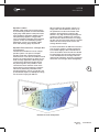
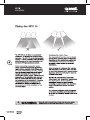
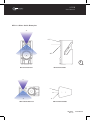
User
Manual
MODEL: HPI 110
Contents
Safety Precautions . . . . . . . . . . . . . . . . . . . . . . . . . . . . 1
General Description. . . . . . . . . . . . . . . . . . . . . . . . . . . . 3
Getting The Best From Your HPI110 . . . . . . . . . . . . . . . 4
Flying the HPI110 . . . . . . . . . . . . . . . . . . . . . . . . . . . . . 6
HPI110 Specifications. . . . . . . . . . . . . . . . . . . . . . . . . . 8
HPI110 Reference Diagram. . . . . . . . . . . . . . . . . . . . . . 9
User Manual
HPI Series
HPI110
HPI110
User Manual
General Description
The HPI 110 is a full frequency range
multi-purpose 2-way passive speaker system
designed for the live sound touring and
permanent installation market.
It is suited to full range front-of house sound
for mid-throw applications in both stand alone
applications or as part of a small array. Its
versatility means it can also be configured
in multiple numbers as a multi-way system
with sub bass enhancement or individually as
part of a compact portable full range system
with single sub bass enhancement. (See HPI
Series bass speaker systems).
The HPI 110 requires no special system
processor and can be installed in a vertical
or horizontal installation with the horn flare
rotated to give the appropriate HF dispersion.
Features
The HPI 110 has a number of features
designed to increase performance and
versatility for a professional sound installation
environment. A great deal of attention
was paid to the details of the design to
make the HPI 110 both sonically excellent
and functionally suited to all aspects of
mobile and permanently installed sound
reinforcement.
The high efficiency 10” neodymium magnet
mid-bass transducer has been designed to
function in a relatively large volume enclosure
to maximize low frequency output. The cone
geometry and driver dynamic parametersare
also engineered to give a smooth frequency
response into the vocal range.
Good vocal and midrange response makes
the HPI-110 an exceptional performer when it
comes to vocal projection and reproduction of
acoustic instrumentation.
Functional Design
For easy maneuvering and loading, an
integrated carry handle also doubles as part
of the rigging system and also serves to give
the casing more strength and rigidity.
The recessed input panel allows for protection
of the plastic Speakon connectors and also
aids a visually tidy installation.
3
Solid Build Construction
Built for a touring environment, the HPI 110
is well suited to all professional applications.
The timber casing is reinforced birch ply with
a heavy gauge power-coated steel grill. Like
all Quest products, it is “built tough for a
tough world”.
High Powered Purpose Designed
Components
A very high powered three inch voice coil
high frequency driver matched to the 1.5
inch exit high frequency asymmetrical wave
guide. The result is a reliable and high fidelity
high frequency response with a long throw
capability.
HPI Series
HPI110
User Manual
HPI110
User Manual
Getting The Best From Your HPI110
Connections
Suitable Amplification
The HPI-110 is an 8 ohm enclosure and can
be connected in multiple parallel connections
to an amplifier channel that can operate
at speaker impedances of 4 ohms. A third
speaker box can be connected in parallel if
the amplifier can operate into loads of less
than 4 ohms. The HPI110 is a mid power level
high efficiency system, so ultra high power is
not necessary to obtain high sound pressure
levels. The recommended power range per
amplifier channel is 600-750 watts RMS into
an 8Ω load or up to 1,200W RMS into a 4 ohm
load. The HPI-110 is ideal for use with any of
the Quest QA amplifier range.
Two Neutric Speakon model NL-4 connectors
are mounted in a recessed panel on the
rear surface of the box. This allows the
speaker box to be set flat against a wall
without physical interference to the speaker
connector.
• The connector input is wired pin 1+ and
pin 1-.
Setting the QA amplifier’s high pass filter
at 35Hz is recommended for full range
applications. If you are intending to add
sub bass speakers or use for mainly vocal
reproduction, the high pass filter can be set
to 80Hz.
• Pin 2 is not connected.
4
Take care when inserting the Speakon
connector twisting the connector until it
locks into place. Reverse the procedure to
disconnect.
10
10
5
5
35Hz
Reducing low frequency output will make more
amplifier power available for clean vocal reproduction
for full range sound, set the high pass filter to 35Hz
80Hz
HIGH PASS -A
1
1
1
OFF
2
OFF
35Hz
80Hz
STEREO PARALLEL BRIDGE
HIGH PASS -A
OFF
LINK A
PIN1:
PIN2:
PIN3:
80Hz
1.4V
MODE
32dB
26dB
GAIN
OUTPUT A
CAUTION
RISK OF ELECTRIC SHOCK
DO NOT OPEN
110Hz
LOW PASS -A
INPUT A
SIGNAL G N D
SIG N AL +
SIGNA L -
BRIDGE
MODEL:
OUTPUT ASSIGNMENT
PIN 1+ :
S IGN A L
PIN 1- :
GROUND
Push To Reset
HIGH PASS -B
OFF
35Hz
80Hz
LIMITER
LOW PASS -B
OFF
LINK B
INPU T B
80Hz
110Hz
ON
GROUND
OFF
LIFT
GROUND
DESIGNED BY QUEST ENGINEERING,AUSTRALIA
OUTPUT B
~ 220
240V 10A 50/60Hz
Recommended HPI110
Amplifier Configuration
User Manual
HPI Series
HPI110
HPI110
User Manual
Speaker cables
Speaker cable needs to be as heavy gauge
as conveniently possible for low-loss results.
Light gauge cable (below 1.5mm) will create
extra resistance and waste amplifier power.
This particularly applies to long speaker
runs. The amplifier’s damping factor statistic
(“punch” for the non technical) is greatly
diminished, so keep your speaker cables
short and as heavy gauge as practical.
Speaker Placement as a Single Box
or in Arrays
The HPI110 is intended for use as a single
speaker system or as part of a multiple
speaker setup with or without sub bass
reinforcement. It can also be installed in small
arrays of up to three boxes per array for very
wide coverage applications. When a group
of point source 90 degree speaker boxes
are placed together, it is possible to have
“interference effect” between some of the
boxes causing uneven frequency response.
This can be particularly noticeable in the
mid-high frequency area. If you intend to set
up the HPI110 as part of a multiple box array,
see the section ‘Flying the HPI110’.
When positioning the speaker system on a
stage, make sure the HF horn at the top of
the speaker box is above the heads of the
audience. At full power the output of the
HPI110 is very high and hearing damage can
result from short to medium term exposure.
When used as a drum-fill monitor on a stage,
the box can sit on the stage however consider
that the HF horn will be at ear level for the
average drummer setup.
For best results when the HPI110 is used as a
front of house speaker, consider angling the
box forward slightly to direct the HF horn to
cover the audience area. The HF horn should
be aimed away from the ceiling and focused
on the intended area of coverage. This will
minimize HF reflections, lower the reverberant
field in the room and give better intelligibility.
5
Ideal HPI110 Flown Configuration
HPI Series
HPI110
User Manual
HPI110
User Manual
HPI 110 Wave Guide Examples
30˚
+15˚
-45˚
45˚
7
HPI110 Vertical Side
HPI110 Vertical Front
30˚
+15˚
45˚
HPI110 Horizontal Front
-45˚
HPI110 Horizontal Side
HPI Series
HPI110
User Manual
HPI110
User Manual
HPI110 Specifications
Typical Frequency Reponse
110
100
90
80
70
60
8
50
20
50
100
200
500
1k
2k
5k
20k
10k
Frequency (Hz)
HPI 110 - Frequency Response - 2.83V/1m
Technical Specifications
User Manual
Power Handling
600W RMS
Frequency Response
60-18kHz (+/-3dB)
Sensitivity
95dB @ 1kHz
Maximum SPL @ 1m
130dB
Impedance
8 ohms
Connections and Wiring
2 x Speakon NL4 - 1+/1- (2+/2- through)
Woofer
10” High Power Mid-Bass Woofer
Tweeter
1” Neodymium Compression Driver
Directivity
Asymmetric +15/-45 Vertical | 30/45
Horizontal
Dimensions
620x380x346.5 mm
Weight
19 kg Net
HPI Series
HPI110
HPI110
User Manual
HPI110 Reference Diagram
9
No.
Description
Spare Part
1
Complete grille (includes glued acoustic foam)
HGHPI110
2
Rotating Q-badge (25mm) with Spring Loaded Pin
HQB25
3
Asymmetric Horn Flare (GT12)
HWG110
4
1.4” Compression Driver
T2005
4bis
Compression Driver Recone (diaphragm)
RT2005
5
10” Woofer
T10003
5bis
10” Woofer Recone Kit
RT10003
6
Steel Pole Bottom Mount Plate
HPP110
7
Rubber skids (137mm)
HSK137
8
Internal Metal Brace - 1 (Top)
HIB110-1
9
Internal Metal Brace - 2(Centre)
HIB110-2
10
Internal Metal Brace - 3(Bottom)
HIB110-3
11
Aluminum HPI Handle
HAH110
12
Connection Plate
HCP110
13
Passive Filter Network for HPI110 (x-over)
AXHPI110
14
Manufacturer Plate for HPI110
HMP110
HPI Series
HPI110
User Manual
Register Your Product
Thank you for choosing Quest. Please take the time
to complete your product registration card which is
included with the packaging.
Registering your Quest Engineering product will:
• CONFIRM YOUR WARRANTY
• REGISTER YOUR PRODUCT
• PROTECT YOUR NEW PRODUCT
REGISTER ONLINE:
www.questaudio.net/registration
www.questaudio.net