1
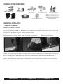
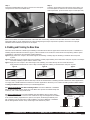
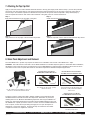
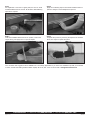
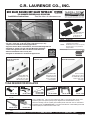
C.R. LAURENCE CO., INC.
GRS GLASS RAILING DRY GLAZE TAPER-LOC™ SYSTEM*
FOR LAMINATED TEMPERED GLASS APPLICATIONS
Installation Instructions
*Patent Pending
See the video at crlaurence.com
Laminated TAPER-LOC™
Sets consist of one
L-Setting Block and
two Tapers Sets
• For Interior and Exterior Railing Applications
• For 9/16" (13.52 mm), 21.52 mm (27/32") and 25.52 mm (1-1/16")
Tempered Laminated Glass Railing Applications
• Supports Surface Mount, Embed Mount, and Fascia Mounting Methods
• Designed for Typical Concrete and Steel Mounting Substrates
• Tested and Engineered to Meet and Exceed Code Standards
• Reduces Installation Labor Time by 50%
• Designed for Residential or Commercial Applications
CAT. NO.
DESCRIPTION
LTL96X
TAPER-LOC™ Set for 9/16" (13.52 mm)
Laminated Tempered Glass
TAPER-LOC™ Set for 21.52 mm (27/32")
and 25.52 mm (1-1/16") Laminated
Tempered Glass
LTL10X
Minimum order 10 sets.
MANUFACTURED IN THE USA
BY C.R. LAURENCE
An ISO9001:2000 Certified Company
ADHERE L-SETTING BLOCK
AND SET THE GLASS INTO
THE BASE SHOE
INSERT TAPERS AND LOCK
USING TLK5 TOOL
ROLL IN THE GLAZING
GASKET AND YOU'RE DONE
Install TAPER-LOC™
Tapers with our TLK5
Installation/Removal
Tool to lock the glass
securely in place.
Adhere TAPER-LOC™
L-Setting Block to the
bottom edge of the glass
and lower it into position.
Roll in the Glazing
Gasket and you're done!
The TAPER-LOC™ System
makes it quick, clean,
and simple.
TOOLS REQUIRED FOR INSTALLATION
CAT. NO. TLK9
inSTallaTion/removal
Tool KiT
CAT. NO. PAL1K
pal Tool KiT
CAT. NO. EBAD2
CAT. NO. EBAD3
maSonry DrillS
CAT. NO. EBADP1
CAT. NO. HRHD1
Hole Blow ouT Tool
roTary Hammer Drill
CAT. NO. 7720H
impaCT SoCKeTS
Crl's Taper-loC™ tools give the installer the ability to accurately shim, plumb, and
install the glass rail system quickly. proper alignment of the Base Shoe is a key
element in making sure the system gets installed plumb and level. See our informative
installation video at crlaurence.com. For technical assistance contact railing Technical
Sales at (800) 421-6144 and ask for ext 7730.
CAT. NO. LTLST3
Temporary SeTTing
Tool
CAT. NO. 54225
Tape rule
crlaurence.com • Phone Toll Free (800) 421-6144 • Fax Toll Free (800) 587-7501
Page 1 of 11
AVD3933 - 7/10
STANDARD SYSTEM COMPONENTS
TAPER-LOC™ Tapers:
High strength reinforced nylon Taper Shims expand in thickness when compressed together with the
TlK9 installation/removal Tool, mechanically locking the glass panel into the Base Shoe.
The installation/removal Tool will also loosen the Tapers for glass panel alignment or
replacement by separating the Tapers.
TAPER-LOC™ L-Setting Block:
High strength reinforced nylon "l" shaped Block spaces the glass away from the Base Shoe's vertical
wall on one side and the bottom edge. Blocks are attached to the glass panel with an adhesive tape
strip that is pre-installed. Blocks serve to insulate the glass panels from damage during insertion into
the Base Shoe, and at the same time center the glass in the pocket. Blocks are black in color.
Heavy Aluminum Base Shoe for Laminated Glazing:
Crl’s High Strength extruded aluminum Base Shoe is pre-drilled to facilitate installation into various
substrates. you can use Taper-loC™ Tapers with our laminated Base Shoe for 9/16" (13.52 mm),
21.52 mm (27/32"), and 25.52 mm (1-1/16") laminated Tempered glazing. Standard lengths are
available in 120" (3.05 mm) and 3 m (118-1/8"). Custom lengths can also be made available on
special order. Important!!! Base Shoe used with the TAPER-LOC™ System must meet the
following glass specifications:
9/16" (13.52 mm) Laminated Tempered Glass (1/4" x .060 x 1/4")
Thickness range 0.497" (12.62 mm) to 0.549" (13.94 mm)
21.52 mm (27/32") Laminated Tempered Glass (10 mm x 1.52 x 10 mm)
Thickness range 20.40 mm (0.803") to 22.94 mm (0.903 mm)
will work with aSTm 7/8" monolithic Tempered glass
will NOT accommodate the full aSTm thickness range for 27/32" glass
25.52 mm (1-1/16") Laminated Tempered Glass (12 mm x 1.52 x 12 mm)
Thickness range 24.40 mm (0.960") to 26.92 mm (1.060")
will work with aSTm 1" monolithic Tempered glass
will NOT accommodate the full aSTm thickness range for 1-1/16" glass
Base Shoe Cladding and End Caps:
our thorough selection of accessories includes everything you need for the installation of finished
railing Systems: base shoe cladding, end caps, fasteners, shims, and vinyl; hand railing tubing,
brackets, and splicers in your choice of many beautiful architectural finishes. go to our web site and
click on the architectural railing Systems Catalog to begin your review of our entire program.
Base Shoe Anchor Bolts:
when mounting the grS glass railing Base Shoe to a concrete substrate use Cat. no. eBa335 HilTi®
Heavy-Duty Sleeve expansion anchors. when mounting the Base Shoe to a steel substrate use Cat.
no. SHCSm14X34 m14 - 2.0 X 20 mm long Hex Head Cap Screws (Din rated) for attachment. anchor
Bolts have been engineered and tested to meet guard rail code requirements.
Top Cap Rails:
our premium Cap rails are available in 2" (50.8 mm) and 2-1/2" (63.5 mm) diameters. u-Channel Cap
rail is also available. precision tooling and finishing techniques assure you a Cap rail of unsurpassed
quality. accessories include Splicing Sleeves, elbow Joints, end Caps, installation vinyl, and metal
Contact Cement for almost seamless joints. go to our web site and search Cap railS for the
complete selection.
Hand Rail Tubing and Brackets:
Crl's round Hand rail Tubing is sold in diameters from 1-1/2" (38.1 mm) to 2" (50.8 mm). Square
Hand rail Tubing is also available in a 1-1/2" (38.1 mm) profile. Hand rail Brackets and accessories
are also available in several architectural finishes. Hand rail Tubing is sold in 20' (6.10 m) lengths.
crlaurence.com • Phone Toll Free (800) 421-6144 • Fax Toll Free (800) 587-7501
Page 2 of 11
AVD3933
STANDARD SYSTEM COMPONENTS
neuTral Cure SiliCone
HanD rail BraCKeTS
glazing gaSKeTS
ClaDDing Tape
SpliCe SleeveS
Top Cap rail enD CapS
aluminum HorSeSHoe SHimS
meTal ConTaCT CemenT
aluminum SHim STripS
GUARD RAIL INSTALLATION
1. Substrate Preparation
Base Shoe Attachments to Concrete
Start by using the holes in the Base Shoe as an alignment fixture for proper hole positioning. Then drill using a rotary Hammer with
the recommended masonry Drill Bit (Cat. no. eBaD3). if re-bar obstruction occurs, additional drilling of Base Shoe may be required.
after drilling, all that is necessary is to clean out the holes with the Blow-out pump (Cat. no. eBaDp1) and install the expansion
Bolt anchor (Cat. no. eBa335). expansion Bolt anchors include washers.
Step 2
Step 3
Step 1
install Crl's expansion Bolt
align the Base Shoe in the proper location Clean out the holes with Crl's Blow
Concrete anchors.
and drill the required holes in the concrete. out pump.
Base Shoe Attachments to Steel Angles, Channels, and Weld Blocks
Start by using the holes in the Base Shoe as an alignment fixture for proper hole positioning. Then drill the holes in the steel and tap
for the m14 - 2.0 x 20 mm Hex Head Screw (Cat. no. SHCSm14X34). after drilling, all that is necessary is to clean out the holes with
the Blow out pump (Cat. no. eBaDp1) and install the m14 Hex Head Screws. if pre-drilled and tapped weld Blocks (Cat. no.
lSwB21 or BSwB5B) are required, it is recommended that the weld Blocks be installed to an adequate steel structure by qualified
welders. a continuous 3/16" (4.8 mm) minimum weld must be applied to opposite sides of the weld Block to meet required loads.
The images following illustrate a weld Block installation.
crlaurence.com • Phone Toll Free (800) 421-6144 • Fax Toll Free (800) 587-7501
Page 3 of 11
AVD3933
Step 1
align the Base Shoe in the proper location, then mark your
attachment hole locations. Field weld Crl's pre-drilled and
tapped weld Blocks to the steel stringer.
Step 3
attach the Base Shoe to the
weld Blocks with Crl's m14
Hex Head Screws or 1/2-13
Socket Head Cap Screws.
Step 4
Tighten each Socket Head
Cap Screw until you achieve
between a 50 and 100 foot
pound rating depending if the
bolt surface condition is wet
or dry.
Step 2
Set Base Shoe in place, making sure the Base Shoe hole
locations match the weld Block hole locations.
2. Base Shoe Attachment
Preparation
IMPORTANT!!! On all installations the mounted base should be adjusted, if required, to assure it is plumb to plus or minus
1/8" (3.2 mm) at an extended height of 42" (1067 mm). Spend the time required to plumb the Base Shoe to this tolerance, as
the glass will only be as plumb as the Base Shoe.
Available Shims for Leveling the Base Shoe:
CRL Cat.
CRL Cat.
CRL Cat.
CRL Cat.
CRL Cat.
CRL Cat.
No. AHS66
No. AHS68
No. AHS64
No. BSS164
No. BSS132
No. BSS116
aluminum Horseshoe
Shims
1/16" x 3" (1.6 x 76.2 mm) aluminum Horseshoe Shims
1/8" x 3" (3.2 x 76.2 mm) aluminum Horseshoe Shims
1/4" x 3" (6.3 x 76.2 mm) aluminum Horseshoe Shims
1/64" (.4 mm) aluminum Shim Strips
1/32" (.8 mm) aluminum Shim Strips
1/16" (1.6 mm) aluminum Shim Strips
aluminum Shim Strips
crlaurence.com • Phone Toll Free (800) 421-6144 • Fax Toll Free (800) 587-7501
Page 4 of 11
AVD3933
Layout and Leveling Procedure
layout the guard rail or windscreen perimeter on the mounting surface with a chalk line. position the first section of Base Shoe,
starting at the beginning of a run or at a corner, and align with the chalk line mark. if the installation requires that the Base Shoe be
level (as opposed to following the slope of the surface) the first section to be installed should be located at the highest elevation.
Start by installing all mounting fasteners hand tight, and then loosen the fasteners for insertion of leveling shims.
Level Base Shoe Installations
when the Base Shoe is to be level, as opposed to following the slope of the surface, it is easier to level the shoe along its length
before correcting the vertical plumb orientation.
Sloped Base Shoe Installations
when the Base Shoe is following a sloping grade the laser level can still be useful for preventing any abrupt elevation changes, and
it is easier to level the shoe along it’s length before correcting the vertical plumb orientation.
align the "pal" Tool with Base Shoe and point toward the
laser Target set at opposite end.
when leveling the Base Shoe to your concrete or steel substrate
make sure you level the shoe within 0.4 degrees of the floor.
angular variation up to 0.4 degree is acceptable during this
process. as you tighten the anchor bolts every 12" (304.8 mm) on
center, slide the digital level along the Base Shoe making sure
the shoe is within specifications. if adjustments need to be made
loosen the anchor bolts and shim as required using Crl's
aluminum Horse Shoe Shims or Shim Strips until your Base
Shoe is within specifications. proper alignment of the Base Shoe
is a key element in making sure the system gets installed plumb
and level. insert shims when mounting surface conditions create
occasional gaps under the Base Shoe. Crl aluminum Horseshoe
Shims up to 1/4" (6.3 mm) thick can be used. good surface
conditions will permit the use of Crl aluminum Base Shoe
ShimStrips. The Shim Strips are available in thicknesses of 1/64"
to 1/16" (.4 to 1.6 mm), and allow for fine adjustment of vertical
plumb. after leveling both ends of a Base Shoe section, place
shims at ALL BOLT LOCATIONS where gaps between the Base
Shoe and mounting surface appear. Both sides of the Base Shoe
must be in contact with the mounting surface and shims before
tightening bolts, or the Base Shoe will twist out of vertical plumb
alignment. Shim Strips should be oriented along the length of the
Base Shoe and must be close to the outer edge. The bottom
surface of Crl Base Shoe is concave to prevent "high centering",
so the outer bottom edges must be in contact with the shims.
laser light pinpoints on lT1 laser Target.
Slide Shim Strips under
Base Shoe to fill gaps.
use the "pal" Tool to assure the Base
Shoe is level at all points. when leveling
the Base Shoe make sure you level the
shoe within 0.4 degrees of the floor.
angular variation up to 0.4 degree is
acceptable during this process.
crlaurence.com • Phone Toll Free (800) 421-6144 • Fax Toll Free (800) 587-7501
Page 5 of 11
AVD3933
Using the GRS PAL Digital Locator
assemble the alignment adapter onto the digital device by aligning the thread in the alignment adapter with the thread on the bottom
of the digital device. Hand-tighten the thumbscrew, being careful that the digital device is seated flat against the alignment adapter.
The large pin protruding from the alignment adapter must be positioned at the center of the pal Digital locator, so please pay
attention to the alignment adapter orientation that best centers the pin. push the power button and the pal is ready for use.
please perform the Self-Check and Calibration procedure as described in user's manual.
Before placing the pal on top of the Base Shoe, wipe the Base Shoe’s top surface clean. The accuracy of the level depends on a
smooth, clean surface and a balanced pal with both top surfaces of the Base Shoe in contact with the pal.
insert the pal alignment adapter pin into the Base Shoe’s pocket with the length of the pal in line with the length of the Base Shoe
for horizontal leveling, or perpendicular to the Base Shoe for vertical plumb adjustment. Start with the horizontal leveling orientation
and perform the end-to-end shimming procedure. The display will indicate with two arrows the direction that the pal needs to rotate
for obtaining plumb or level. The pal has two displays. The left hand display is for leveling, and the right hand display is for indicating
angles with the protractor arm.
406065
pal Digital locator
pal Carrying Case
406065
pal Digital locator
ama1
alignment adapter
Standard Base
Shoe Channel
ama1
alignment adapter
lT1 laser Target
Correcting Out of Plumb
The mounted base should be adjusted, if required, to assure that it is plumb to plus or minus 1/8" (3.2 mm) at an extended height of
42" (1067 mm). To accomplish this the angle indication display must read from one end of the Base Shoe to the other within 0.4
degrees. angular variation up to 0.4 of a degree is acceptable if the variation from one Base Shoe to the next is leaning to the same
side of vertically plumb. with the pal oriented perpendicular to the Base Shoe, take a reading at three or four locations along the
Base Shoe’s length, inserting shims as you go along.
Shim Thickness Selection
0.4 of a degree equals 5/16" (8 mm) out of position at 42"
(1067 mm) above the mounting surface. when installing Crl
4" (102 mm) tall Base Shoe, insertion of a 1/64" (.4 mm) thick Shim
Strip will move the 0.4 reading back to zero. Tighten the mounting
bolts to the correct torque, and then double check the vertically
plumb orientation.
Digital level Side
angle Side
Display for Digital level and angle locator.
Horizontal Leveling
Starting with the first Base Shoe segment that is located at the highest elevation, perform the end-to-end leveling operation,
and then adjust the vertical plumb orientation. now place the pal in line with the Base Shoe’s length. push the laser button
to activate the laser. AVOID EXPOSURE TO THE LASER LIGHT. install the next Base Shoe, aligning the top surfaces with the
adjacent Base Shoe, and at the opposite end place the laser Target on top of the Base Shoe with it’s targeting line facing the laser
source. Shim the Base Shoe until the laser light is centered on the targeting line. leave the laser on the first Base Shoe to perform
this function for all Base Shoes up to a 100' (30 m) long run. The pal can be moved to a previously leveled Base Shoe closer to the
new work area if the run exceeds 100' (30 m). each new run direction should repeat this process. it is undesirable to turn the laser
perpendicular to the Base Shoe for leveling of an adjacent run of Base Shoe. IMPORTANT!!! The Laser does not level itself,
so occasionally check the level angle display as you work.
crlaurence.com • Phone Toll Free (800) 421-6144 • Fax Toll Free (800) 587-7501
Page 6 of 11
AVD3933
Following a Grade
The pal’s laser is not self-leveling, and because of this it is appropriate for use on sloping grades, stairs, and ramps. adjust the Base
Shoe’s vertically plumb orientation. now place the pal in line with the Base Shoe’s length. push the laser button to activate the laser.
AVOID EXPOSURE TO THE LASER LIGHT. install the next Base Shoe, aligning the top surfaces with the adjacent Base Shoe, and
at the opposite end place the laser Target on top of the Base Shoe with it’s targeting line facing the laser source. Shim the Base
Shoe until the laser light is centered on the targeting line. leave the laser on the first base shoe to perform this function for all Base
Shoes up to a 100' (30 m) long run. The pal can be moved to a previously leveled Base Shoe closer to the new work area if the run
exceeds 100' (30 m). each new run direction should repeat this process. it is undesirable to turn the laser perpendicular to the Base
Shoe for leveling of an adjacent run of Base Shoe. Sometimes grades will not angulate, so it may be necessary to move the laser’s
location to compensate. The laser’s purpose in this application is to avoid abrupt elevation changes that look unsightly.
Using the Angle Locator
The angle locator (protractor arm) is very useful for making field layout drawings and setting Base Shoe corner angles. Simply
loosen the locking screw and unfold the angle locator arm. match the angle of subject surfaces and read the angle indication from
the right hand display. Depressing the HolD button is useful for retaining the angle information when working blind.
unfold locator arm.
match angle of subject surface.
read angle indicator.
3. Prep the Glass for Installation
Before installation of the glass panels the l-Setting Blocks must be adhered onto the bottom of each glass panel. remove the tape's
liner strip and stick the l-Setting Blocks onto the bottom edge of the glass with the vertical surface making glass contact. Space
Blocks at 14" (356 mm) on center maximum or use a minimum of four blocks for a 48" (1219 mm) glass panel (reference chart below).
exact spacing is not necessary. For small glass panel width conditions at stairways and ramp returns only one l-Setting Block is
required.
Required Quantity:
Panel Width
1 Taper-loC™ Set
6" to 14" (152 to 356 mm)
14" to 28" (356 to 711 mm)
2 Taper-loC™ Sets
28" to 42" (711 to 1067 mm)
3 Taper-loC™ Sets
42" to 56" (1067 to 1422 mm)
4 Taper-loC™ Sets
56" to 70" (1422 to 1778 mm)
5 Taper-loC™ Sets
70" to 84" (1778 to 2134 mm)
6 Taper-loC™ Sets
6" (152 mm) edge distance
make sure the Taper-loC™ spacing does
not exceed 14" (356 mm) on center.
is recommended for most
standard applications.
SYSTEM FOR 200 LB. (90 kG) POINT LOAD WITH 4X SAFETY FACTOR
Taper-loC l-preSSure BloCK
™
A
eDge DiSTanCe SpaCing
B
CenTer line SpaCing
Taper-loC™ TaperS
TYPICAL BASE SHOE ELEVATION
DETAIL WITH TAPER-LOC™ LOCATIONS
A: The Taper-loC™ minimum edge distance
spacing shall not be less than 2" (51 mm)
and no more than 8-5/8" (219 mm) from the
edge of glass to edge of the
Taper-loC™ components.
B: The Taper-loC™ maximum center-to-center
spacing shall not be less than 7" (178 mm)
and no more than 14" (356 mm) from the
center line of the Taper-loC™ Tapers.
Before the glass is installed into the Base Shoe the installer should consider if Crl's
Fast-Seal glazing vinyl will be advantageous for the installation. Crl's Fast-Seal glazing vinyl was developed for balcony edge
conditions that are difficult to access. our Cat. no. BSg250 vinyl eliminates the difficulty and risk of reaching over the glass edge to
roll in typical glazing vinyl. For more information regarding Crl's Fast-Seal System, please visit our web site at crlaurence.com.
crlaurence.com • Phone Toll Free (800) 421-6144 • Fax Toll Free (800) 587-7501
Page 7 of 11
AVD3933
4. Glass Panel Installation
To begin the installation of the glass panels, first make sure the Base Shoe is free of debris. place the glass with the l-Setting Block
into the Base Shoe's pocket. make adjustments if required. Blocking can be added if one corner of the panel is low. The glass can be
held in a near vertical position by inserting one laminated Taper-loC™ Taper Set at each end of the glass panel. Important!!! One
Taper in each set has "Glass Side" engraved on it. This surface must face and touch the glass panel. The other Taper has
projecting rails along it's length that hold Tapers in alignment with each other. align the two Tapers and spread them apart until the
assembly is thin enough to fit into the slot. partially insert the Tapers into the slot between the glass and Base Shoe, squeeze
together with very light finger pressure, and push down into the Base Shoe. This will apply some clamping force and aid with
alignment. when the installer is satisfied with the spacing and top height alignment for a group of panels the Taper-loC™
securing operation may begin.
Step 1
Squeeze the Tapers together finger tight and push the set
half way down into the windscreen Base Shoe as shown.
Step 2
use the TlK9 installation/removal Tool to push the Tapers down into
position for the next step, locking the Tapers together.
5. Securing the TAPER-LOC™ Glass Panels in the Base Shoe
Taper-loC™ Systems are self-centering and self-plumbing. Remember the glass will follow the Base Shoe alignment, so spend
the time required to plumb the Base Shoe to + or – 1/8" (3.2 mm) at 42" (1067 mm) extended. wood wedges are not required
if you plumb the Base Shoe correctly. partially insert the remaining Taper-loC™ Tapers into the slot between the glass and Base
Shoe, squeeze together with very light finger pressure, and push down into the Base Shoe as shown in Step 4. Don't worry about
trying to push the Tapers all of the way into the Base Shoe, as the installation Tool will take care of this for you. NOTE: The right
side of the right hand Taper must be aligned with the right hand vertical edge of the Setting Block.
it is a good idea to lock-up both ends of each panel and double check alignment before locking the Tapers in between. insert the
installation/removal Tool's blades into the slot between the glass and Base Shoe. using the Torque wrench, bring the blades closer
together by depressing the left side ratchet direction button, crank on the wrench or push the torque wrench's right side ratchet
direction button to spread the blades apart until they align with the Taper slots. The tool should now be able to drop down until it
comes to rest on the Base Shoe. This action will push the Taper the remaining depth into the Base Shoe. The top of the tool has
a black indication mark at the right hand side that must be aligned with the right side vertical edge of the Setting Block (visible looking
through the glass). Sliding the tool left or right will move the Tapers at the same time to achieve alignment.
press the left side ratchet direction button to lock the Tapers together. Then (if you are right handed) position yourself to the left side
of the tool, grab the tool's left side handle with your left hand, and crank the Torque wrench with your right hand, being careful to hold
the tool in alignment with the Setting Block. when the correct lock-up force is applied the wrench will make a single clicking sound,
and will break for a few degrees of rotation. Important!!! If you are not certain that the wrench made the clicking sound, do not
apply more force than the factory pre-set. Unlock the Tapers and lock-up once again. Repeat this process for the remaining
Tapers. Over-torquing will eliminate the ability to unlock the Tapers with the Installation/Removal Tool,
making glass panel removal very difficult.
crlaurence.com • Phone Toll Free (800) 421-6144 • Fax Toll Free (800) 587-7501
Page 8 of 11
AVD3933
Step 1
place the installation/removal Tool into position onto the Tapers
and push them down into the Base Shoe.
Step 2
Crank the Torque wrench until the wrench clicks, letting you
know the Tapers are locked to the correct measured torque
value requirement. (Continue these steps for each Taper Set)
make sure the blade movement mechanism of the TlK9 Tool moves freely, and hasn't become filled with dust or debris. Blade
mechanisms that are poorly maintained may cause binding during the Taper compression operation, and result in an improper
installation with insufficient compression of the Tapers.
6. Cladding and Finishing the Base Shoe
There are various methods of attaching the Cladding to the Base Shoe. all three types shown below will work, but a combination of
Cladding Tape and neutral Cure Silicone (Type C) offers the better of two worlds; the instant bond of the tape along with the speed
of application of the silicone and its flexible, durable adhesion.
Type A: apply three rows of Tape to the vertical edge of the Cladding. Carefully align the Cladding to the Base Shoe and press
in place.
Type B: apply Silicone to the vertical edge of the Cladding. Carefully align Cladding to the Base Shoe and press in place. use clamps
to hold the Cladding in place until the Silicone cures.
Type C: apply two rows of Tape to the vertical edge of the Cladding, one toward the top and one toward the bottom.
apply the Silicone between the rows of Tape. Carefully align the Cladding to the Base Shoe and press in place.
Type A
Type B
Type C
once the Cladding is applied the last and final step to finish off the Base Shoe is installing the roll-in gasket for interior applications,
or to apply Crl's 95CBl neutral Cure Silicone for exterior applications. we invite you to contact our railing Technical Sales Division
at [email protected] to discuss your individual application.
For Interior Applications use Roll-In Glazing Gasket: use Crl's lBSg100 or lBSg500
roll-in glazing gasket to finish off the top of the Base Shoe pocket. The gasket easily rolls
in with any one of Crl's vinyl roller Tools.
For Exterior Applications: use Crl's BSg250 Fast Seal glazing vinyl for glass railing
applications where there is no access to the outside shoe edge. it's designed to be installed
to the outside cladding edge before the glass is set in place, eliminating the difficulty and
risk of reaching over the guard rail for seal installation. use Crl's lBSg100 or lBSg500
roll-in glazing gasket to finish off top inside edge of the base shoe pocket.
lBSg100 or
lBSg500
roll in vinyl
INTERIOR APPLICATIONS
BSg250
FaST Seal
EXTERIOR APPLICATIONS
crlaurence.com • Phone Toll Free (800) 421-6144 • Fax Toll Free (800) 587-7501
Page 9 of 11
AVD3933
7. Attaching the Top Cap Rail
apply a continuous bead of Crl's 95CBl Structural Silicone to the top glass edge (shown below in Step 1). Secure the protective
vinyl insert onto glass edge (Step 2), then apply another bead of Structural Silicone to the top edge of the vinyl insert (Step 3).
The last step is to install the Cap rail over the Silicone and protective vinyl insert until the Cap rail is firmly seated (Step 4).
Shim as required and caulk on both sides at the underside of the glass pocket for a clean finished look.
Step 1
Step 2
apply Structural Silicone to the top edge of the glass.
install the protective vinyl insert.
Step 3
apply Silicone to the top edge of the protective vinyl insert.
Step 4
install the Cap rail over the Silicone and protective vinyl insert.
8. Glass Panel Adjustment and Removal
The Crl Taper-loC™ System only requires the TlK9 Tool for installation and removal of the Taper-loC™ Taper.
CAUTION: The TlK9 Tool Kit comes with a set of Blades installed for monolithic tempered glass. For laminated glass installations,
the Blades on the tool kit will need to be switched out for the TlB6r Blades for laminated glass installations before the tool can be
used. each tool kit comes complete with blades for monolithic tempered and laminated tempered applications.
STANDARD INSTALLATION BLADES
FOR B5S, B5T, AND B7S BASE SHOES
CaT. no. TlK5 inSTallaTion/removal Tool For
monoliTHiC & laminaTeD TempereD glaSS
CaT. no. TlB5 replaCemenT BlaDeS For
1/2" (12 mm) (15 mm) or 3/4" (19 mm)
monoliTHiC glaSS
To adjust or remove a glass panel that is already installed, use the standard TlK9
installation/removal Tool Kit and follow the steps below. remember to protect the
cladding with Cat. no. Bl992 2" Blue masking Tape when removing the Taper-loC™
Tapers. For glass railing applications insert Crl's TlK9 installation/removal Tool over
the Taper-loC™ Tapers you wish to remove or loosen. once the installation/removal
Tool is in place, reverse the torque setting and apply force to open the Tapers for
adjustment or removal as required. Continue this step as needed for the number
of Tapers that need to be adjusted or removed.
EXTENDED BLADES FOR FASCIA MOUNT
L56S, L21S, AND L25S BASE SHOES
AND
CaT. no. TlB6r replaCemenT BlaDeS For
9/16" (13.52 mm), 21.52 mm (27/32") anD
25.52 mm (1-1/16") laminaTeD TempereD
appliCaTionS
STANDARD INSTALLATION BLADES
FOR W5B WINDSCREEN BASE SHOES
CaT. no. TlB3 replaCemenT BlaDeS
For 3/8" (10 mm) glaSS
crlaurence.com • Phone Toll Free (800) 421-6144 • Fax Toll Free (800) 587-7501
Page 10 of 11
AVD3933
Step 1
For adjustment or removal of a glass panel, the Cat. no. TlK9
installation/removal Tool and Cat. no. Bl992 2" Blue masking
Tape will be required.
Step 2
apply the 2" masking Tape to the finished cladded surface to
protect it during this removal/adjustment process.
Step 3
insert the installation/removal Tool into position, reverse the
torque setting, and apply force to open the Tapers.
Step 4
Complete the process by removing the Tapers from the Base
Shoe, then adjust or replace the panel.
your comments and suggestions about Taper-loC™ are always appreciated. if you have some installation tips that you would like
to share, contact Crl railing Technical Sales at (800) 421-6144, ext. 7730. or send e-mail to [email protected]
crlaurence.com • Phone Toll Free (800) 421-6144 • Fax Toll Free (800) 587-7501
Page 11 of 11
AVD3933