1
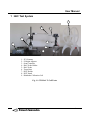
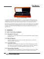
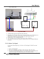
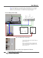
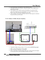
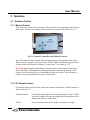
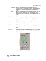
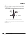
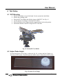
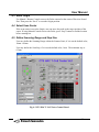
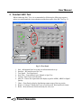
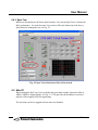
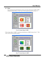
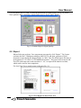
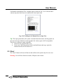
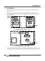
User Manual
CTS HAC Tester
User Manual
V4.1
Crescendo Tech Services
San Diego, CA
CCrreesscceennddoo TTeecchh S
Seerrvviicceess
-1-
User Manual
Table of Content
Change History ............................................................................................................................... 4
1
HAC Test System .................................................................................................................. 6
2
Installation.............................................................................................................................. 7
2.1
HAC T-Coil Tester Installation ...................................................................................... 7
2.1.1
Assemble X-Y Scanner........................................................................................... 7
2.1.2
Mount Z Support..................................................................................................... 7
2.1.3
Install HAC Probe................................................................................................... 7
2.1.4
Connect Scan Controller ......................................................................................... 7
2.1.5
Connect Cables ....................................................................................................... 8
2.1.6
Assemble DUT Holder ........................................................................................... 8
2.2
Sound Card Installation................................................................................................... 8
2.2.1
Install Sound Card in PC......................................................................................... 8
2.2.2
Install Sound Card Driver ....................................................................................... 9
2.2.3
System Setup......................................................................................................... 12
2.3
SW Installation and Setup............................................................................................. 13
2.3.1
Install HAC T-Coil Test System Software ........................................................... 13
2.3.2
Running CTS HAC T-Coil Tester ........................................................................ 13
2.3.3
RS-232 Control Port Setup ................................................................................... 14
2.3.4
System Calibration................................................................................................ 15
3
Operation.............................................................................................................................. 23
3.1
Scanner Control ............................................................................................................ 23
3.1.1
Manual Control ..................................................................................................... 23
3.1.2
PC Remote Control ............................................................................................... 23
3.2
Adjust Probe Height...................................................................................................... 25
3.3
Change Probe Direction................................................................................................ 25
4
Test Setup............................................................................................................................. 26
4.1
DUT Mounting.............................................................................................................. 26
4.2
Adjust Probe Height...................................................................................................... 26
4.3
Reset Origin .................................................................................................................. 27
4.4
Select Scan Center ........................................................................................................ 27
4.5
Define Scanning Range and Step Size.......................................................................... 27
5
Conduct HAC Test............................................................................................................... 28
5.1
Test Info. ....................................................................................................................... 29
5.2
Interface ........................................................................................................................ 30
5.3
Test Signals................................................................................................................... 30
5.4
Scan Type...................................................................................................................... 31
5.4.1
Auto Scan.............................................................................................................. 31
5.4.2
Manual Scan.......................................................................................................... 31
5.4.3
Spot Test ............................................................................................................... 32
5.5
Max Of .......................................................................................................................... 32
5.6
HAC Test ...................................................................................................................... 33
5.6.1
Axial (Z) Test........................................................................................................ 33
CCrreesscceennddoo TTeecchh S
Seerrvviicceess
-2-
User Manual
5.6.2
Radial (Y) Test...................................................................................................... 33
5.6.3
Radial (X) Test...................................................................................................... 33
5.7
Chart.............................................................................................................................. 34
5.8
Report............................................................................................................................ 35
5.9
Reset.............................................................................................................................. 36
6
Test Methods........................................................................................................................ 37
7
Error and Trouble Shooting ................................................................................................. 38
8
Contact & Technical Support............................................................................................... 40
9
Acronym .............................................................................................................................. 40
10 References............................................................................................................................ 40
CCrreesscceennddoo TTeecchh S
Seerrvviicceess
-3-
User Manual
Change History
(Latest Update at Top)
Rev. 4.1 – Released June 22, 2009
• Changed Scan Area from Square to Rectangular with user defined sizes in three
directions.
• Program will be installed and running at, “C:\CTS HAC Tester” folder.
• Serial Port Auto Detection.
• Report Template in MS Word.
Rev. 4.0 – Released March 28, 2009
• Add Helmholtz Calibration Coil function to do the HAC probe calibration.
• Add CMU Vocoder Calibration procedure.
• Add “Monitor Tool” for quick audio test.
• Add Interface for user to choose the CMU Vocoder and ensure the Test Injection Level
meet standard requirement.
• Add Manual Scan and Spot Test.
• Auto Scan test can be conducted with Wideband Test Signals.
• Add “Max of” selection to choose HAC Rating and Result Analysis options.
• Enhanced Generator Level control to be smart according to Standard requirement.
• Add “Info” Panel “Save”, “Load” and “Clear” functions for easy information
management.
• Add “Reset” Button.
Rev. 3.0 – Released July 24, 2007
• Implemented Wide Band Test at Sweet Spots.
• Z Height Adjust changed in hardware.
Rev. 2.0 – Released June 22, 2007
• Implemented according to ANSI C63.19-2007.
• Included Contour Map of ABM1 for all three directions.
• Enhanced Test Report Content. Added Contour Maps, Output Test Data of Frequency
Response and Scanning Data.
Rev. 1.2 -- Released on May 22, 2007
• Section 2.2.3, correct “Scanner Control” to “Config”.
CCrreesscceennddoo TTeecchh S
Seerrvviicceess
-4-
User Manual
Rev. 1.1– Released April 20, 2007
• Typo Corrections.
Rev. 1.0 – Released March 12, 2007
• Original Document.
CCrreesscceennddoo TTeecchh S
Seerrvviicceess
-5-
User Manual
1 HAC Test System
9
4
5
2
1
7
3
8
6
1 – X-Y Scanner
2 – Z Height Adjuster
3 – Scan Controller
4 – HAC Probe Holder
5 – HAC Probe
6 – Tester Base
7 – DUT Holder
8 – DUT Stand
9 – Helmholtz Calibration Coil
Fig. 1-1 CTS HAC T-Coil Tester
CCrreesscceennddoo TTeecchh S
Seerrvviicceess
-6-
User Manual
Fig. 1-2 CTS HAC Probe
CTS HAC T-Rating Probe is shown as in Fig. 1-2. The unit includes a calibration data sheet
should always stay with the probe and its box. If the probe is broken, a new probe needs to be
installed for measurement. If the calibration data is in doubt, a new calibration is needed.
Special care is needed when using the probe. Please do not twist the Probe cable. It may damage
the cable connection. When installing the Probe, be careful of the surroundings. It needs some
clearance for the Probe movement. When the Probe is not in use, please store it back to its
protective box.
2 Installation
2.1 HAC T-Coil Tester Installation
2.1.1 Assemble X-Y Scanner
Assemble the two Linear Stages into an X-Y position with the flange supplied. Properly
tighten the screws.
2.1.2 Mount Z Support
Install the Z support on top of Y-Axis. Let the HAC Probe pointed to +X direction.
Assemble the HAC Probe Holder.
2.1.3 Install HAC Probe
Loose the HAC Probe Holder screw. Slide the HAC Cable through the gap. Insert the
HAC Probe extension tube into the Holder. Align the marker with the gap. Tighten the
screw. The Probe should be at Z direction and can be twisted to ±90° freely.
2.1.4 Connect Scan Controller
Connect the Motor Cable Connectors to X/Y Jack. Connect the Controller to PC Serial
Port with RS-232 None-Modem cable. Note the PC Port Number (to be used for PC
CCrreesscceennddoo TTeecchh S
Seerrvviicceess
-7-
User Manual
Setup). Connect the power core to 100~240VAC. Turn on the Power and test the Manual
Control Buttons of the Scanner Motion.
2.1.5 Connect Cables
Connect the HAC Probe Cable to the MIC/Direct Input Jack of the Sound Card. Connect
the Speaker Output of the Sound Card to the driving point of DUT.
2.1.6 Assemble DUT Holder
Assemble the DUT Holder as shown in Fig. 2-1.
Fig. 2-1 DUT Holder
2.2 Sound Card Installation
The instruction illustrated here is exclusively for MAYA 44 v3.0 shown as Fig. 2-2. If user
uses other brand sound card, please refer to the Instruction Manual of the card used for
related information.
Fig. 2-2 MAYA 44 v3.0 Sound Card
2.2.1 Install Sound Card in PC
Follow the instruction of the Sound Card to install the Sound Card into one of the PCI
interfaces in the PC. Be sure to fasten the card steady.
CCrreesscceennddoo TTeecchh S
Seerrvviicceess
-8-
User Manual
2.2.2 Install Sound Card Driver
Insert the Sound Card Installation disc into CD Driver. Follow the instructions to
properly install the Sound Card Driver.
Sound Card Setting
After the installation, please set up the Sound Control of the PC as following.
• Go to Control Panel, select “Sounds and Audio Devices”.
• In “Audio” and “Voice” Tabs, choose “MAYA44V3Ch34” for Playback. Choose
“MAYA44V3Ch1234” for Recording. Shown as in Fig. 2-3.
Fig. 2-3 Sound Card Channel Selection.
•
Click “Volume” icons for “Sound Playback” and “Sound Recording”. Set the volume
to Max. Set mute feature identical as if Fig. 2-4.
Fig. 2-4 Volume Control & Mute
CCrreesscceennddoo TTeecchh S
Seerrvviicceess
-9-
User Manual
•
Click the “Advanced” button in “Sound Playback” field. Select “Stereo Headphones”
in “Speaker Setup”, shown as in Fig. 2-5. This will give a better impedance match if
user drive component directly (Output Load ~ 32 Ohms).
Fig. 2-5 Speaker Setup
•
Double-Click the icon indicated in Fig. 2-6 for detail Sound Card Settings.
Fig. 2-6 MAYA44 v3 Setting Icon.
CCrreesscceennddoo TTeecchh S
Seerrvviicceess
- 10 -
User Manual
•
The window shown in Fig. 2-7 will pop-up. Set the parameters as identical as shown
in Fig. 2-7.
Select “ANA”
for Analog
Interface.
“HP” for
Headphone.
Select Mic
to enable
42dB Gain.
Ensure 0.0dB
Gain.
Clock & Fs
setting.
Fig. 2-7 MAYA 44 v3 Configuration
•
Sound Card Control Setting Finished.
CCrreesscceennddoo TTeecchh S
Seerrvviicceess
- 11 -
User Manual
2.2.3 System Setup
Ana1
Ana2
Ana Output 12
Gen.
Coax Dig.
Opt. Dig.
Sound Card Connector
CMU200
Audio Out
Audio In
Computer
Serial Port
Fig. 2- 8 System Hardware Setup.
Cabling:
•
•
•
•
•
Ana1 to HAC Probe.
Ana2 to Control Box Mon.
Gen. to CMU200 Audio In, or to Phone Directly or to Control Box Audio In.
Control Box Audio Out to Helmholtz Coil.
Serial Port to Control Box Serial Port.
CCrreesscceennddoo TTeecchh S
Seerrvviicceess
- 12 -
User Manual
2.3 SW Installation and Setup
2.3.1 Install HAC T-Coil Test System Software
Insert the HAC T-Coil Test System Software disc into CD Driver. Run the setup.exe to
install the HAC T-Coil Test System Software. User may use the default setup to install
the software.
2.3.2 Running CTS HAC T-Coil Tester
On Desktop, double click “CTS HAC T-Coil Tester” shortcut to run the system. The
running UI is shown as Fig. 2-9.
Fig. 2-9 Test System Running Window
CCrreesscceennddoo TTeecchh S
Seerrvviicceess
- 13 -
User Manual
2.3.3 RS-232 Control Port Setup
Rev. 4.1 can automatically detect the serial ports available to the PC. If there is only one
port is available, program will automatic use this port as the control interface of the
scanner. If there more than one port at present, it will pop up a selection window and list
all the ports for user to choose. Please choose the correct port and click “OK”. See Fig.
2-10.
Fig. 2-10 Serial Port Selection for Scanner Control.
If there is NO Serial Port at present, it will pop up a warning window to alert User. And
the Program will be stopped. Please connect to serial port cable properly and restart the
program.
CCrreesscceennddoo TTeecchh S
Seerrvviicceess
- 14 -
User Manual
2.3.4 System Calibration
1
2
3
Fig. 2-11 Sound Card Calibration Setup
Click “System Calibration” from the main window. Then click “Calibrate”. User can then
select which part of the system needs to do the calibration as shown in Fig. 2-11.
CCrreesscceennddoo TTeecchh S
Seerrvviicceess
- 15 -
User Manual
2.3.4.1 Signal Generator Calibration
Ana1
Ana2
Ana Output 12
Gen.
Coax Dig.
Opt. Dig.
Sound Card Connector
DMM
CMU200
Audio Out
Audio In
Computer
Serial Port
Fig. 2-12 Calibrate Generator.
•
•
•
•
•
•
Connect Gen to a DMM (Digital Multi-Meter as shown in Fig. 2-12.
Select “Generator Calibration”.
System generates a 1 KHz sine tone from Sound Card target at -20dBV (100mV).
Read the signal level in dBV and enter the value in the pop-up window and then
hit “OK”.
Until you see -20.0dBV from the reference Analyzer/DMM, the SW will
automatically update the Calibration Data and reconfirm the Sound Card Output
Level.
When the Output level is -20.0dBV, SW will save the Calibration Data and turn
off the signal output.
CCrreesscceennddoo TTeecchh S
Seerrvviicceess
- 16 -
User Manual
2.3.4.2 Analyzer Calibration
Ana1
Ana2
Ana Output 12
Gen.
Coax Dig.
Opt. Dig.
Sound Card Connector
DMM
CMU200
Audio Out
Audio In
Computer
Serial Port
Fig. 2-13 Cal Ana1.
There are two Analyzers need to be calibrated, Ana1 and Ana2. Ana1 is with 42 dB
gain of pre-amplifier. Ana2 is a direct input line.
First Calibrate Ana1:
• Connect Ana1 to Gen. as shown in Fig. 2-13.
• Select the field of Calibration and Select “Analyzer Calibration”.
• A dialog window pops up to confirm the cable connection. The Gen outputs a
level of -60dBV 1 KHz tone for Ama1 calibration.
• The system will automatically calibrate the Analyzer and save the Calibration
Data into the system.
CCrreesscceennddoo TTeecchh S
Seerrvviicceess
- 17 -
User Manual
Next, Calibrate Ana2.
Ana1
Ana2
Ana Output 12
Gen.
Coax Dig.
Opt. Dig.
Sound Card Connector
DMM
CMU200
Audio Out
Audio In
Computer
Serial Port
Fig. 2-14 Cal Ana2.
•
•
•
•
•
A dialog window pops up to adjust the cable connection.
Disconnect Ana1 (Warning: This has to be disconnected before proceed. Otherwise, it is
HIGH RISK to damage the Sound Card Input when high voltage is injected.
Connect Ana2 to Gen. as shown in Fig. 2-14.
The Gen outputs a level of -20dBV 1 KHz tone for Ama1 calibration.
The system will automatically calibrate the Analyzer and save the Calibration Data into
the system.
2.3.4.3 Calibrate Test Signals
Use the same Cable setup as Fig. 2-14. Select “Cal Test Signals”. DO NOT use Ana1
Channel.
•
•
•
Select “Cal Test Signals”.
The system will pop-up a reminder for cable connection. Then click “OK”.
The system will automatically calibrate all 7 test signals and store all the data to the
system for test usage. The calibration may take a few minutes to finish.
CCrreesscceennddoo TTeecchh S
Seerrvviicceess
- 18 -
User Manual
Note: Custom Signals have to be named as either “Custom Signal 1.wav” or “Custom
Signal 2.wav”. Other names will not be recognized by the test system. The test signal
files have to reside at this folder, “C:\CTS HAC Tester\Config\Test Signals”.
2.3.4.4 Calibrate HAC Probe
Ana1
Ana2
Ana Output 12
Gen.
Coax Dig.
Opt. Dig.
Sound Card Connector
CMU200
Audio Out
Audio In
Computer
Serial Port
Fig. 2-15 Calibrate HAC Probe Setup.
Connect all the cables for Cal HAC Probe as
shown in Fig. 2-15.
Make sure the HAC Probe is aligned at the
center of the Helmholtz Calibration Coil as
shown in Fig. 2-16.
Fig. 2-16 HAC Probe Alignment for Calibration.
In the SW window, select “Cal HAC Probe”.
CCrreesscceennddoo TTeecchh S
Seerrvviicceess
- 19 -
User Manual
•
•
•
•
A pop-up message will remind user of the calibration setup.
The system will first to build-up the calibration magnetic field at 0dB(A/m) by
monitoring with Ana2.
When magnetic field is settled, system will remind user to position the HAC
probe at the calibration position of Helmholtz Coil Center. Make sure that the
Probe is in the same direction of Helmholtz Coil’s axial.
Click “Continue”, the System will measure the HAC Probe output level and store
the probe sensitivity to the system.
2.3.4.5 Calibrate Call Box Encoder Sensitivity
Ana1
Ana2
Ana Output 12
Gen.
Coax Dig.
Opt. Dig.
Sound Card Connector
Computer
CMU200
Audio Out
Audio In
Serial Port
Fig. 2-17 Calibrate Call Box Encoder Sensitivity.
•
•
•
•
Connect the Cables as shown in Fig. 2-17. Use Ana2 only. DO NOT use Ana1.
Make a call to Wireless Device from Call Box.
Select Vocoder on CMU200 to “Cal Decoder”.
Select “Cal Encoder” from the System. The system will first measure the Output
level from Decoder for Decoder Calibration and save the data.
CCrreesscceennddoo TTeecchh S
Seerrvviicceess
- 20 -
User Manual
•
•
The System will remind User to change Vocoder to “Cal Encoder”. Then click
“Continue”.
The System will then generate -20dBV signal to do the calibration and save the
data to the system.
2.3.4.6 Monitor Tool
Ana1
Ana2
Ana Output 12
Gen.
Coax Dig.
Opt. Dig.
Sound Card Connector
CMU200
Audio Out
Audio In
Computer
Serial Port
Fig. 2-18 Monitor Tool
CCrreesscceennddoo TTeecchh S
Seerrvviicceess
- 21 -
User Manual
The Monitor Tool is designed for easy use of conducting any audio test. It provides a Sine Tone
generator and a Real Time Voltage Monitor with Ana2. User can use it for a quick verification in
any audio tests.
2.3.4.7 Finish Calibration
When Calibration is finished, select “Stop”. The Calibration window will disappear and
return to the Main Test Window.
CCrreesscceennddoo TTeecchh S
Seerrvviicceess
- 22 -
User Manual
3 Operation
3.1 Scanner Control
3.1.1 Manual Control
Turn on the power of the Scan Controller. Press any button corresponding to the direction,
the Scanner will move accordingly. Release the button, Scanner will stop. See Fig. 3-1.
Fig. 3-1 Scanner Control Box with Manual Controls.
Note: The Manual Control motion will not automatically give the position of the probe.
When motion is stopped, user may press the “STOP” button in SW Panel to get the exact
location of the Probe from the readings of “Scan Center”. See details in 3.1.2.
Warning: When manually controlling the Scanner, please always watch for the motion
limit of the Slides. Although there is design protection to minimize the damage of the
Scanner, User should always avoid to running the slides to its limits. This will ensure a
longer life time and maintain the accuracy of the system.
3.1.2 PC Remote Control
PC Remote Control can be used to control the motion of the Scanner. All the controls are
shown in the Fig. 3-2.
“Motion Control”:
Controls the motion direction and stops the motion. When “STOP”
is pressed, Scanner will stop any motion and Probe position will be
displayed in the field “Scan Center”.
“Mode”:
User can set the motion in two modes: Continuous or Stepper.
CCrreesscceennddoo TTeecchh S
Seerrvviicceess
- 23 -
User Manual
Continuous – When an Arrow button is pressed, the Scanner will move
continuously until “STOP” button is pressed. When stopped, Probe
position will be automatically displayed in the field of “Scan
Center”.
Stepper –
When an Arrow button is pressed, the Scanner will only move the
distance specified in the “Step Size” then stop. When stopped,
Probe position will be automatically displayed in the field of “Scan
Center”.
“Set O”:
Whenever the power of the Scan Control box is turned on, the
current Probe position is defined as “Origin” of the system. User
may redefine the current location as a new “Origin” by press “Set
O” button.
“Scan Center”:
Defines the Scanning Center location. It also indicates the current
location when adjust Scanner position.
“Step Size”:
Defines the motion distance of each move and the step sizes when
conducting scan test. The minimum step is 0.5mm, while default is
1mm.
“Scan Area”:
Defines the Scanning Area with Rectangular shape. User needs to
define it for all three scanning directions. Default is, Z: 20x20; Y:
10x30; X: 30x10.
Fig. 3-2 PC Remote Motion Controls
CCrreesscceennddoo TTeecchh S
Seerrvviicceess
- 24 -
User Manual
3.2 Adjust Probe Height
The HAC Probe height can be adjusted with a manual slide rail, shown as in Fig. 3-3. The
Position Lock can fix the Probe at a proper height. Then use the Fine Adjust to adjust the
exact height of the Probe.
• Unlock the screw for the position lock.
• Press the Handle to move upward. Press the Release Handle to lower the Probe.
Position
Lock
Turn Probe
Fine Adjust
Fig. 3-3 Probe Height Adjustment and Probe Orientation Control
3.3 Change Probe Direction
Turn the “Turn Probe” 90º can change the Probe from Axial direction to Radial direction
or back forth. See Fig. 3-3.
CCrreesscceennddoo TTeecchh S
Seerrvviicceess
- 25 -
User Manual
4 Test Setup
4.1 DUT Mounting
•
•
•
•
•
•
Put the DUT Holder on top of the Stand. Use the suction lock the Holder.
Release the Grabbing Arms.
Place the DUT on Holder and slide the Arms to hold DUT. See Fig. 4-1.
Use the Space-Level Gauge to level the DUT surface.
Place the Holder so the Scanner located at approximately in the mid position.
Position the Holder so that DUT align with X-Y direction.
Fig. 4-1 Position DUT on Holder
4.2 Adjust Probe Height
Use the 2mm Spacer-Level Gauge, as shown in Fig. 4-2, to ensure the HAC Probe is at
2mm above DUT surface. This will ensure the Probe center is 10mm above DUT surface.
Fig. 4-2 Spacer-Level Gauge
CCrreesscceennddoo TTeecchh S
Seerrvviicceess
- 26 -
User Manual
4.3 Reset Origin
Use Manual / Remote Control to move the Probe centered at the center of Receiver Sound
Port. Then press the “Set O” to reset the Origin position.
4.4 Select Scan Center
If the scan center is not at the Origin, user can move the probe to the target position of the
center. If using Manual Control to move the Probe, press “Stop” button to read the location
before running test.
4.5 Define Scanning Range and Step Size
User may define the Scanning Range within the Scanner Limit, if it is not the default value,
10mm x 10mm.
User may define the Scan Step, if it is not the default value, 1mm. The minimum step is
0.5mm.
Fig. 4-3 CTS HAC T-Coil Tester Control Panel.
CCrreesscceennddoo TTeecchh S
Seerrvviicceess
- 27 -
User Manual
5 Conduct HAC Test
When conducting HAC Test, it is recommended to following the following sequence,
unless user understands the test mechanism and the data report of the SW. See Fig. 5-1.
6
1
7
5
8
2
4
3
9
Fig. 5-1 Test Panel
1.
2.
3.
4.
5.
6.
Info – Information Panel to record test information and set up.
Interface – RF interface used for Test.
Test Signal – Test Signal used.
Scan Type – Scan method, Auto, Manuel or Spot Test.
Testing – Start Test at each direction.
Max Of – Choose the report and result display regard to ABM1, ABM2 or Signal
Quality.
7. Chart – Chart Panel to display distribution contour maps of the test results.
8. Report – Evaluate T Rating and Create a Test Report in Word and Excel format.
9. Reset – Reset all the test results and ready for a new test.
CCrreesscceennddoo TTeecchh S
Seerrvviicceess
- 28 -
User Manual
5.1 Test Info.
Click “Info” tab to enter all the related information of the test as in Fig. 5-2.
Fig. 5-2 Test Conditions and Information
Besides, User can use “Load” to recall saved Info File’ “Save” to store the Info into the
system. Click “Clear” will reset all the Info fields.
CCrreesscceennddoo TTeecchh S
Seerrvviicceess
- 29 -
User Manual
5.2 Interface
User can run the test with their proper Air Interface for the HAC Test. If User chooses
CMU200 as the RF interface, the System will automatically set the Signal Generator
output level to the correct test levels, i.e. -16 dBm0 for GSM and -18 dBm0 for CDMA.
If User chooses “Handset Low” for GSM or “8K EVRC” for CDMA, User can only use
1025Hz Tone to run the tests. Other Wideband test signals will not be able to meet the
signal output level requirement due to the capacity of the Sound Card.
If User choose “Direct” interface, the Generator output level will be dBV. User then can
change the output level according to test needs.
5.3 Test Signals
The system provides total of 7 test signals for HAC test. They are 1025Hz Tone, P50-Male,
P50-Female, White Noise, Pink Noise, Custom Signal 1 and Custom Signal 2. The Wide
Band Signals take longer time for one test. Therefore it is recommended to use them for
Spot Test.
User can choose or modify “Custom Signal 1” or “Custom Signal 2”. Custom Signals
should be stored in the folder located at “C:\CTS HAC Tester\Config\Test Signals” with
the same name as, “Custom Signal 1.wav” or “Custom Signal 2.wav”.
CCrreesscceennddoo TTeecchh S
Seerrvviicceess
- 30 -
User Manual
5.4 Scan Type
There are three methods to conduct HAC Test, Auto Scan, Manual Scan or Spot Test.
5.4.1 Auto Scan
The system will scan the area defined by Scan Size and Step Size. It will record all the test
data, ABM2, ABM2, Signal Quality and Frequency Response in the area. It also indicates
the progress of the scanning test, see Fig. 5-3. When finishing the scanning, it will find out
the sweet spots for each test direction for Test Report.
Fig. 5-3 Auto Scan Status.
5.4.2 Manual Scan
Manual Scan allows User to manually search for the Sweet Spot. The System will pop-up a
Test Monitor Window to track the Peak level, shown as Fig. 5-4. User controls the Scanner
with the Control Box. When the Max Value is located, Press “Finish” button. The system
will record the Sweet Spot and HAC test result.
Fig. 5-4 Manual Scan Monitor.
CCrreesscceennddoo TTeecchh S
Seerrvviicceess
- 31 -
User Manual
5.4.3 Spot Test
When user already knows the Sweet Spot locations, User can run Spot Test to evaluate the
HAC performance. For each direction, User needs to fill in the dimension of the Sweet
Spot before the running the test, see Fig. 5-5.
Fig. 5-5 Spot Test & Selection of Max Value Search.
5.5 Max Of
When running the HAC test, User can define the report data whether is based on Max of
ABM1, ABM2 or Signal Quality. See Fig. 5-5. This provides the flexibility for test and
analysis of the magnetic field for engineering.
The selection can also be toggled after the auto scan finished.
CCrreesscceennddoo TTeecchh S
Seerrvviicceess
- 32 -
User Manual
5.6 HAC Test
5.6.1 Axial (Z) Test
It is always recommended to conduct the Axial (Z) Test first because of the Sweet Spot
position report method.
• Make sure the HAC Probe is at Axial Test Direction.
• Position the HAC Probe at the Scan Center position and make sure it is 2mm above
DUT surface.
• Click the “Axial (Z) Test Start” to start the test. When the Probe and DUT position
are all correct, click “OK” in the reminder window.
• SW will automatically scan the area to find out the Sweet Spot and move to the Sweet
Spot to conduct ABM1, ABM2, Signal Quality and Frequency Response tests. The
results will be displayed on screen. Note: the Frequency Response is referenced to the
level at 1 KHz.
• After finishing the test, Probe will move back to the Origin position.
5.6.2 Radial (Y) Test
•
•
•
•
•
Turn the HAC Probe to Radial Test Direction.
Make sure the HAC Probe is at the Origin and it is 2mm above DUT surface.
Click the “Radial (Y) Test Start” to start the test. When the Probe and DUT position
are all correct, click “OK” in the reminder window.
SW will automatically scan the area to find out the Sweet Spot and move to the Sweet
Spot to conduct ABM1, ABM2, and Signal Quality. The results will be displayed on
screen.
After finishing the test, Probe will move back to the Origin position.
5.6.3 Radial (X) Test
•
•
•
•
•
•
The HAC Probe stays at Radial Test Direction.
Turn DUT Holder 90º (Anti-Clockwise is required to make coordinate consistent).
Make sure the HAC Probe is at the Origin and it is 2mm above DUT surface.
Click the “Radial (X) Test Start” to start the test. When the Probe and DUT position
are all correct, click “OK” in the reminder window.
SW will automatically scan the area to find out the Sweet Spot and move to the Sweet
Spot to conduct ABM1, ABM2, and Signal Quality. The results will be displayed on
screen.
After finishing the test, Probe will move back to the Origin position.
CCrreesscceennddoo TTeecchh S
Seerrvviicceess
- 33 -
User Manual
5.7 Chart
After Auto Scan tests of all directions, User may view the contour maps of ABM1, ABM2
and Signal Quality (SNR) in “Chart” Panel. Click the panel tap, shown as in Fig. 5-6.
Fig. 5-6 Contour Maps of ABM1
If User chooses Max of “ABM2”, it will show the distribution of ABM2, shown as Fig. 5-7. This
can be used for the noise pattern analysis.
Fig. 5-7 Contour Maps for ABM2
CCrreesscceennddoo TTeecchh S
Seerrvviicceess
- 34 -
User Manual
User can choose Max of “SNR” to show the distribution of Signal Quality, as Fig. 5-8. When
Noise pattern is high, sometimes, Signal Quality may be favor of the T-Rating.
Fig. 5-8 Contour Maps for Signal Quality.
5.8 Report
When all the tests are done, User can generate test report by click “Report”. The System
evaluates the HAC T-Rating according to ANSI C63.19 and, then, generates a Word
document as specified in the “Report Folder” in “Info” Tab. The default report file name is
in the pattern of “CTS-HAC-YYYYMMDD-hh-mm.doc”. The system also creates an MS
Excel file with same name with extension of “.xls”, to export all the numeric test data,
which can be used for later comparison.
For Auto Scan Test, a sample report is shown in Fig. 5-9.
Fig. 5-9 Test Report for Pure Tone Test.
CCrreesscceennddoo TTeecchh S
Seerrvviicceess
- 35 -
User Manual
For Manual Scan and Spot Test, a sample report is shown in Fig. 5-10. It does not have
contour map since these tests are conducted at Sweet Spots only.
Fig. 5-10 Test Report for Manual Scan or Spot Test.
Tip: The report generated by the system is an html format document. All the graphics in
the report are hyper-linked to external graphic file. So the report is NOT real portable.
There are two options to make it portable,
• Convert it into a pdf file and save it.
• Create a new Word document which is not html format and copy / paste the
contents into the new file and save it.
5.9 Reset
The “Reset” Button will reset all the test data and have the system ready for a new test.
Warning: User will lose all the test results, if Report is not created.
CCrreesscceennddoo TTeecchh S
Seerrvviicceess
- 36 -
User Manual
6 Test Methods
There are two ways of testing HAC T Rating for a wireless device, Callbox Test Mode or
Loop Test Mode.
In Callbox Test Mode, Audio Signal passes through Call Box encoder and WD decoder.
This can be illustrated as Fig. 6-1. This is a straight forward method and it emulates the real
network performance.
-16dBm0/
-18dBm0
A/D
RF De-Mod
Encoder
Decoder
RF
Modulator
D/A
BS
ABM1
WD
Fig. 6-1 Signal Path in Call Box Test Mode.
Equivalent
Signal Level
WD
A/D
Tx Gain
Internal Loop
BS
D/A
Rx Gain
ABM1
Fig. 6-2 Signal Path in Loop Test Mode.
In Loop Test Mode, Audio Signal passes an internal audio loop in WD for the test. This can
be illustrated as Fig. 6-2. This can avoid any potential problem with sine tone with Vocoder.
CCrreesscceennddoo TTeecchh S
Seerrvviicceess
- 37 -
User Manual
7 Error and Trouble Shooting
Frequently Asked Questions:
Manual Control of the Scanner does not Work.
• Check the Motor Cables/Connectors are properly installed.
• Check the power core and Power Switch is “ON”. Power Lit should be light-up.
• Press the Direction Buttons. Scanner should move accordingly.
• If not, contact CTS for further trouble shooting.
Software Controlled Scanner Movement does not Work.
• Check the RS-232 Cable connection.
• If control still not working, Power Cycle the Control Unit and the PC. Normally it
will clean up the communication line.
What to do if the Scanner hit the end of its travel and motor has skipped turns?
• Normally when this happens, the Controller will have mismatch of the location of
the scanner. User needs to reset the Origin to recapture the coordinates.
• Warning: Although this device has been designed to minimize the damage of the
motion elements when over-travel happens, it is highly recommended that user
pay close attention not doing so often. Whenever this happens, user should
immediately stop the motion by either push the “Stop” Button or switch off the
Control Unit.
There is no sound coming out of the DUT.
• First check the cables from Sound Card to DUT.
• Check the DUT setting. Making sure that the DUT audio path is set up properly.
• Check the PC Sound Out Level Control. Make sure that speaker is not Muted and
the Volume is at Maximum.
• If it still not working, user may need to restart the Program / PC to reinitialize the
Sound Card / PC.
There is no Signal from the Measurement.
• Measure the DC impedance of the Probe. Make sure that the impedance is about
900Ω. If not, the Probe is broken and need a replacement.
• Check the cable connection to Sound Card is correct.
• Check the PC Sound Input selection is corresponding to Cable connecting channel.
• If it still not working, user may need to restart the Program / PC to reinitialize the
Sound Card / PC.
CCrreesscceennddoo TTeecchh S
Seerrvviicceess
- 38 -
User Manual
The sensitivity of HAC probe changes too much.
• Sometimes, when the doing the HAC Probe calibration with Helmholtz Coil. The
sensitivity changes significantly (more than 2 dB). Please check the probe
alignment first before accept the new calibration data. Normally the sensitivity is
around -60.5 dBV/(A/m).
CCrreesscceennddoo TTeecchh S
Seerrvviicceess
- 39 -
User Manual
8 Contact & Technical Support
CTS is committed to provide professional solutions to our customers. We look forward to a
long term partnership with our customers. If you have any issue regarding CTS products,
please do not hesitate to contact us. We will be at your service to meet your satisfaction at
any time.
Crescendo Tech Services
12313 Katydid Circle
San Diego, CA 92129
U. S. A.
Tel. / Fax: +1-858-780-9881
Email: [email protected]
http://www.crescendotek.com
9 Acronym
ABM –– Audio Band Magnetic.
ABM1 –– Desired Audio Band Magnetic Field
ABM2 –– Undesired Audio Band Magnetic Field
ANSI –– American National Standard Institute.
CTS –– Crescendo Tech Services.
dB(A/m) – dB reference to 1 A/m.
dBV –– dB reference to 1 V.
dBm0 –– The power in dBm measured at a zero transmission level point.
DMM –– Digital Multi Meter.
DUT –– Device Under Test.
HAC –– Hearing Aid Compatibility.
IEEE –– Institute of Electrical and Electronics Engineers.
PC –– Personal Computer.
S/N –– Signal Noise Ratio.
SW –– Software.
10 References
ANSI C63.19-2007, “Methods of Measurement of Compatibility between Wireless
Communications Devices and Hearing Aids”, IEEE 3 Park Avenue, New York, NY 100165997, USA, 8 June 2007.
AduioTrak Inc., “User’s Manual for MAYA 44 V3”, Version 1.0, 20050705.
CCrreesscceennddoo TTeecchh S
Seerrvviicceess
- 40 -