1
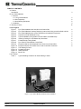
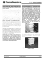
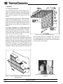
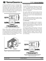
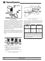
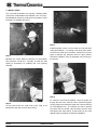
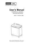
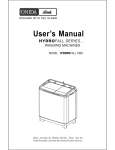
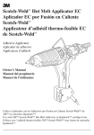
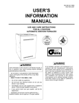
PYRO-FOLD® M™
MODULE
DESIGN AND INSTALLATION
MANUAL
Thermal Ceramics
TABLE OF CONTENTS
A. Preface
Introduction
B. Pyro-Fold M Module
1. General
1.1 Lining Considerations
1.2 Site Preparation
1.3 Stud Welding Equipment
2. Installation
C. Glossary of terms
3
4
6
6
9
12
List of Figures
Figure 1
Pyro-Fold M Module with Stud Gun and Control Box
Figure 2
Pyro-Fold M Module Cutaway Displaying Internal Anchoring as well as Stud and Nut
Figure 3
Pyro-Fold M Module with Anchor Hardware and Installation Equipment
Figure 4
Typical Pyro-Fold M Module Lining
Figure 5
Typical Installation using Soldier Course Pattern with Batten Strip
Figure 6
Inserting Packing Pin into Batten Strip Overhead
Figure 7
Folded Module Cutting Detail
Figure 8
Pyro-Fold M T-Bar Module Corner Block
Figure 9
Equipment Set-Up with Separate Power Source and Control Box
Figure 10 Equipment Set-up with Power Source and Control Box Combined
Figure 11 The Welding Process
Figure 12 Portable Stud Gun
Figure 13 Weld Inspection
Figure 14 Bend Test
List of Tables
Table 1
Typical Welding Conditions for Stud Welding of Steel
Figure 1 - Pyro-Fold Y Module, Stud Gun and Control Box
Page 2
Thermal Ceramics
2
3
4
4
5
5
6
7
8
8
DESIGN & INSTALLATION MANUAL
PYRO-FOLD M MODULE
INTRODUCTION
PYRO-FOLD M MODULE
Over the past 80 years, Thermal Ceramics has proven
itself to be a world leader in solving problems for heatintensive industries.
The Pyro-Fold M Module is a folded module system
designed for industrial applications that require corrosion
barriers, a back-up blanket layer or a pre-layed-out stud
system. The Pyro-Fold M Module is composed of ceramic fiber blanket accordion folded to form the module. The
folded blanket is precompressed in one direction and
banded. The anchor hardware consists of an internal M
yoke in the center of the module and two support tubes.
The Pyro-Fold M Modules are available in 8# pcf and
9.3# pcf densities (128 and 149 kg/m3) and in thicknesses from 4 to 12 inches (102 to 305 mm). These modules
can also be made using any of our standard blanket
chemistries to suit the particular furnace application, i.e.,
Kaowool®
S,
Cerablanket ®,
Cerachem ®
and
®
Cerachrome . The internal anchor hardware is made of
304SS. The necessary studs, nuts and installation tools
are purchased separately.
The refractory ceramic fiber manufactured by Thermal
Ceramics is a highly versatile material. It can be spun or
blown into bulk, air-laid into a blanket, folded into modules, formed into monolithic modules (Pyro-Bloc ®), converted into boards and shapes, die-cut into gaskets, twisted into yarns, woven into rope and cloth, and blended
into liquid binders for coatings and cements. With this
wide range of products, Thermal Ceramics can provide
exactly the right product, or engineered system to fit your
requirements. Thermal Ceramics has an experienced
staff of refractory specialists to assist you in product
selection, system design, and installation techniques.
Thermal Ceramics has enjoyed great success with its
ceramic fiber products due to their cost-effectiveness and
excellent insulating properties. They are lightweight and
have low thermal conductivities, excellent resistance to
thermal shock, outstanding electrical resistivity, and good
acoustical properties.
This Design and Installation Manual is intended to give
the designers, installers, and users of Thermal Ceramics
ceramic fiber products a broad range of information on
how to select the most appropriate fiber system for a particular application, necessary design criteria, and how to
correctly install the selected system.
PLEASE NOTE: This manual has been designed to easily accommodate new or revised information. Holders of
the manual are advised to keep their address current with
the Advertising and Sales Promotion Department at
Thermal Ceramics in Augusta, Georgia. Any questions or
comments regarding this manual should be addressed to
your local Thermal Ceramics representative.
Figure 2 - Pyro-Fold M Module Cutaway
The installation equipment and tools described in this
manual have been developed to ensure a quick, reliable
installation.
Figure 3 - Pyro-Fold M Module with Anchor Hardware and
Installation Equipment
December 2002
Thermal Ceramics
Page 3
1. GENERAL
1.1 Lining Considerations
A Pyro-Fold M Module lining is best installed using a
soldier course pattern utilizing a folded batten strip.
Figure 4 shows how a typical Pyro-Fold M Module
lining would be installed on the walls and roof of a
furnace.
In high temperature applications, it is best to limit the
length of the folded batten strips to 121/2 feet in order
to minimize the effect of shrinkage. The ends of the
batten strips should be tightly compressed into the
adjoining batten strip or preferably shiplapped as in
Figure 5.
In overhead applications, the folded batten strip
must also be pinned to the modules using the
Thermal Ceramics T/C-403 packing pin. It is important to insert this packing pin on an angle as shown
in Figure 6 in order to ensure the legs of the packing
pin do not fall in the fold of a module.
Prior to installing the Pyro-Fold M Modules, it is necessary to lay out the necessary stud pattern and weld the
studs in place. At this point, a stalastic coating can be
applied to the steel casing followed by a layer of blanket
for back-up as well as a layer of stainless steel foil for a
vapor barrier if required. The specific operating conditions for your particular furnace will determine the need
for stalastic coatings, back-up blanket and vapor barriers.
Figure 4 - Typical Pyro-Fold M Module Lining
Once the studs and back-up materials are in place, the
Pyro-Fold M Modules can be installed. The yoke in the
Pyro-Fold M Module has an offset to allow for the stud to
be in the center of the module.
Figure 5 - Typical Installation Using Soldier Course Pattern
with Batten Strip
Page 4
Thermal Ceramics
Figure 6 - Inserting Packing Pin into Batten Strip
Overhead
DESIGN & INSTALLATION MANUAL
PYRO-FOLD M MODULE
The Pyro-Fold M Module can be cut or trimmed to allow
for obstructions such as burners or peepsites. Best
results will be achieved if the module is trimmed equally
from opposite sides of the module, so that the stud will
remain centered as closely as possible. This point is outlined in the cutting detail in Figure 7. It is best to cut less
than what is necessary and compress the module into
place to ensure the tightest possible joint.
1.2 Site Preparation
The steel surface to be lined should be free of heavy rust
or scale, non-conductive paints, dried refractory cements
or oil. Sandblasting, wire brushing or grinding will be
required to clean the surface, or at least the area where
the stud is to be attached.
Set up good scaffolding so there will be easy access to
the areas to be lined. Also, make arrangements for the
material to be as close to the work area as possible without being in the way, so it can be efficiently delivered to
the work crews.
The steel shell should preferably be 10 gage or thicker.
This will minimize difficulty with blowing holes in the steel
while trying to weld the studs in place.
1.3 Stud Welding
The process of arc stud welding involves the same principles as any other arc welding process. 1) Creation of
welding heat by developing an arc between the stud and
the plate. 2) Bringing the two pieces together when the
proper temperature is reached.
Figure 7 - Typical Pyro-Fold M Cutting Detail
Bullnose areas present a challenge for folded module
systems. These areas are best accommodated by utilizing a Pyro-Fold M T-Bar corner block as shown in Figure
8 or a stacked module of similar configuration. These corner block modules can be specially designed to match
the specific requirements of the furnace.
The equipment needed includes a stud gun, a control unit
and an adequate DC welding current supply. The stud is
loaded into the properly sized chuck, the ceramic ferrule
is placed in position over the end of the stud and the gun
is properly positioned for welding. The gun, control unit
and welding machine are connected as shown in Figure
9 or 10 for welding.
Figure 8 - Typical Pyro-Fold M T-Bar Corner Block
Figure 9 - Equipment Setup with Separate Power
Source and Control Box
December 2002
Thermal Ceramics
Page 5
Figure 10 - Equipment Set-up With Power Source and
Control Box Combined
Figure 12 - Portable Stud Gun
The welding process is shown in Figure 11. A solenoid
coil within the gun is energized when the trigger is pulled.
This lifts the stud off the plate and creates an arc. The
end of the stud and the plate are melted by the arc. Upon
completion of the preset arc period, the welding current is
automatically shut off. The mainspring within the gun
then plunges the stud into the molten pool on the plate to
complete the weld. The gun should then be lifted off the
stud and the ferrule broken off.
To set up the gun for shooting studs, set the plunge
length to approximately 1/8 inch (3.2mm) (Figure 12). The
approximate settings for weld time and weld current is
provided in Table 1.
STUD
Weld Base
Diameter
(in.)
(mm)
Weld Time
(Cycles)*
Weld Current
(Amperes)
/4
6.4
10
400
/16
7.9
15
500
3
/8
9.5
20
550
7
/16
11.1
25
675
1
/2
12.7
30
800
*60 cycles = 1 second
The above settings may vary due to the power source, condition of the work piece, age of equipment, length of cable
used between power source and the control unit and the
alloy to be used. After determination of proper settings, the
unit is ready to weld studs.
1
5
Installation rates for welding studs in this manner will vary
with the size of the stud and other working conditions.
However, an average rate is approximately six studs per
minute.
Table 1 - Typical Welding Conditions for Stud Welding of Steel
(A) Gun is properly positioned.
(B) Trigger is depressed and stud is lifted, creating
an arc.
(C) Arcing period is completed, and stud is plunged into
the molten pool of metal on the base metal.
(D) Gun is withdrawn from the welded stud, and ferrule is
removed.
Figure 11 - The Welding Process
Page 6
Thermal Ceramics
DESIGN & INSTALLATION MANUAL
PYRO-FOLD M MODULE
The most common method for testing the welds is the
bend test. This is carried out by striking the stud with a
hammer or by using a bending tool such as a pipe (Figure
14). In the case of a good weld, the stud will break before
the weld. In either case, the testing will damage the stud,
so shoot the test studs on a separate plate or be prepared to grind smooth the area and reshoot.
Figure 14 - Bend Test
As with any welding process, the operator should understand the process, properly maintain the equipment and
follow proper safety precautions.
(A) Good stud weld with a good flash formation
(B) Stud wel in which plunge is too short
(C) Hang-up
(D) Poor alignment
(E) Stud weld made with insufficient heat
(F) Stud weld made with excessive heat
Figure 13 - Weld Inspection (Good and Bad Welds)
December 2002
Thermal Ceramics
Page 7
2. INSTALLATION
The Pyro-Fold M Modules are typically installed soldier
course with a folded batten strip between rows. The PyroFold M Module requires a pre-layed-out stud pattern so the
first step is to establish the layout.
Step 3
Step 1
Measure the correct distance vertically and horizontally
and mark with a chalk line. Typically, for walls the stud
spacing is horizontally 12" (305mm) and 13 1/2" (343mm)
vertically.
Install the plastic covers over the studs and coat the steel
casing with stalastic. If a coating is not being used, plastic
covers for the studs are not needed. At this point, back-up
layers of blanket and stainless steel foil vapor barriers
should be installed if being incorporated into the lining of
the furnace.
Step 4
Step 2
At the points where the chalk lines cross, weld an M
Module two step stud onto the steel casing.
Page 8
To install the Pyro-Fold M Module, insert the guide rod
through the hole in the yoke tab, lift the module and guide
rod into position and thread the guide rod onto the small tip
on the M Module stud. The module can now be pushed
into place with the module yoke tab sliding onto the stud
and against the steel casing. A slide plate can be used
against adjoining modules to ease the installation.
Thermal Ceramics
DESIGN & INSTALLATION MANUAL
PYRO-FOLD M MODULE
Step 5
Step 8
Insert a hexnut into the end of the nut driver and slide
onto the guide rod. Thread the nut by hand onto the stud.
Remove the guide rod.
Lay folded batten strip in place on top of installed row of
modules before installing the next row of modules.
Step 6
Using a ratchet or drill, tighten the nut onto the stud.
Step 9
When all the Pyro-Fold M Modules have been installed,
the banding strips should be cut and removed.
Step 7
Push the fiber together to eliminate the hole in the center
of the module.
December 2002
Thermal Ceramics
Page 9
Step 10
The final step should be to tamp out the lining, to further
tighten all joints and close any gaps that may exist.
Notice:
Some of the products described in this literature contain
Refractory Ceramic Fiber (RCF) and/or crystalline silica
(cristobalite or quartz). Based on experimental animal
data, the International Agency for Research on Cancer
(IARC) has classified RCF, along with fibrous glasswool
and mineral wool, as a possible human carcinogen
(Group2B) and respirable crystalline silica as a probable
human carcinogen (Group 2A).
To reduce the potential risk of health effects, Thermal
Ceramics recommends engineering controls and safe
work practices be followed by product users. Contact the
Thermal Ceramics Product Stewardship Group (1-800722-5681) to request detailed information contained in its
MSDSs and product literature and videos.
Page 10
Thermal Ceramics
CERAMIC FIBER SYSTEMS: DESIGN & INSTALLATION MANUAL
GLOSSARY OF TERMS
Amorphous: Having no definite crystalline structure or form.
Back-up Insulating Material: The layer or layers of insulating
material that are located between the hot face insulating layer and
the outer casing.
Blanket: A flexible unbonded ceramic fibrous insulating material of
reasonably determinate dimensions.
Board: A substantially rigid or semi-rigid flat sheet produced by
vacuum forming.
Lock Washers: Washers used in conjunction with Kao-Lok studs.
They are slotted so that when pushed over the stud and then twisted 90° the washer is locked into place, other locking systems are
available, such as cone anchors. Lock anchors come in ceramics
or alloy metals to suit temperature requirements.
Maximum Temperature Rating: The temperature which is used
by the industry as a loose classification of different grades of
ceramic fiber. This is generally higher than the continuous use limit.
Bulk Fiber: Ceramic fibers in the “as-produced” state.
Module: A prefabricated unit which can be applied as a lining
block to the inner face of a furnace structure.
Butt Joint: A ceramic fiber wallpaper construction joint where
edges of adjacent blankets meet.
Mortar/Cement: A ceramic-based adhesive for attaching ceramic
fiber products to other surfaces.
Cold Face Temperature: Term used to denote the outside casing
temperature.
Mullite: A crystalline phase of alumina-silica.
Continuous Use Limit: Long-term (continuous) temperature limit
for a product installed as a lining. This temperature is based upon
product shrinkage, specifically what is considered to be a “manageable” or “controllable” shrinkage. This term is not to be confused
with temperature rating.
Cristobalite: A crystalline phase of silica which will begin to form
above 1800°F.
Devitrification: The phase transformation from glass to crystalline
structure.
Edge-grain: The orientation of a fiber system in which strips of
ceramic fiber blanket or felt are oriented perpendicular to the plane
of the furnace casing.
Felt (Pressed): A flexible sheet product formed from ceramic
fibers and bonded with an organic binder.
Heat Loss: The term used to denote the amount of heat being lost
through a lining construction over time, measured in BTU/sq ft/min,
(watts/sq in).
Heat Storage: The thermal property of a material wherein heat
accumulates in the mass (which in refractories is a function primarily of the material’s specific heat, mass, and temperature rise measured in Btu/lb/°F (Cal/g/°C).
Heat Transfer: The study of heat flow mechanisms - conduction,
convection, and radiation.
High Alumina Fiber: A ceramic fiber containing more than 90%
alumina, giving a high use limit. Mullite fiber is also used in high
temperature applications.
High Purity (HP) Fiber: A ceramic fiber produced from synthetic
alumina and silica.
Hot Face Insulating Material: The layer of lining insulating material that has at least one surface exposed to the full temperature of
the furnace gases.
Kaolin Fiber: A ceramic fiber produced from calcined kaolin.
Laminar Flow: The flow of a gas in which the gas stream moves
in straight lines parallel to the direction of the flow.
Layered Lining Wallpaper: Lining that is composed of several
layers and thicknesses of refractory ceramic fiber.
Linear Shrinkage: The amount of shrinkage which occurs
along the length of a material after it has been subjected to elevated temperatures and then cooled - measured in percent of original
prefired length.
December 2002
Overlap Construction: A construction technique used to accommodate shrinkage in ceramic fiber or to improve velocity resistance
in which one edge of a blanket is lapped over an adjacent blanket
edge by 4" to 12" and shares a common anchor stud and washer.
Paper: A roll product produced from ceramic fibers and organic
binders on conventional paper-making machinery.
Parquet: A method of installing modular edge-grained forms of
ceramic fiber so that the edge grain of one module is perpendicular
to the edge grain of the adjacent modules.
Rigidizing: The practice of applying an inorganic hardening agent
to the surface of ceramic fiber (by spray or brush) in order to
improve its velocity resistance.
RCF: Refractory Ceramic Fiber.
Shingled Joint: A method of applying double layers of ceramic
fiber blanket in such a way that half the width of each layer overlaps
half the width of the adjacent layer.
Shot: A glassy material formed during fiberization.
Textile: Cloth, tape, sleeving, tubing, or other forms manufactured
from ceramic fiber yarn.
Thermal Conductivity: The property of material to conduct heat measured in Btu flow per hour through a square foot of area across
one inch of thickness Btu•in/hr•ft•°F (w/m •C°).
Thermal Resistivity: The property of a material to resist the flow
of heat; the reciprocal of thermal conductivity.
Thermal Shock: A failure mechanism wherein sudden changes in
temperature bring sufficient thermal mechanical stress in a material to cause cracking or spalling. As a general rule, the thermal
shock resistance of a material is greater as the strength and thermal conductivity of a material increase and as the thermal expansion and modulus of elasticity decrease.
Turbulent Flow: Fluid flow in which the velocity of a given stream
of gas changes constantly both in magnitude and direction.
Vacuum Forming: A method of producing molded shapes and flat
board by converting fibers into a slurry and vacuuming them onto a
screen former.
Veneer: Layer of ceramic fiber in either blanket or module form
which is attached to the hot face of a brick, module or monolithic
lining.
Wallpaper Construction: The term used to describe a ceramic
fiber lining construction technique where the blanket is installed on
a wall like a roll of wallpaper.
Thermal Ceramics
Page 11
For further information, contact your nearest Thermal Ceramics technical sales office, e-mail
[email protected] or visit us on the web at www.thermalceramics.com.
Global Headquarters
Thermal Ceramics Global
L'Européen - Bât. C
2, rue Joseph Monier
92859 Rueil-Malmaison Cedex, France
T: +33 (0)1 47 16 22 23
F: +33 (0)1 47 16 22 40
E-mail: [email protected]
Global Marketing Offices
Thermal Ceramics Americas
2102 Old Savannah Road
Augusta • Georgia • 30906
T: +1 (706) 796 4200
F: +1 (706) 796 4398
E-Mail: [email protected]
Thermal Ceramics Asia Pacific
28 Jalan Kilang Barat
Kewalram House
Singapore • 159362
T: +65 6273 1351
F: +65 6273 0165
E-mail: [email protected]
Thermal Ceramics Europe
Tebay Road • Bromborough • Wirral
CH62 3PH • England
T: +44 (0) 151 334 4030
F: +44 (0) 151 334 1684
E-mail: [email protected]
Sales and Marketing Office Locations
North America - Sales Offices
Canada
T: +1 (905) 335 3414
F: +1 (905) 335 5145
Mexico
T: +52 (555) 576 6622
F: +52 (555) 576 3060
United States of America
Eastern Region
T: +1 (800) 338 9284
F: +1 (866) 785 2764
Western Region
T: +1 (866) 785 2738
F: +1 (866) 785 2760
South America
Argentina
T: +54 (11) 4373 4439
F: +54 (11) 4372 3331
Brazil
T: +55 (21) 2418 1366
F: +55 (21) 2418 1205
Chile
T: +56 (2) 854 1064
F: +56 (2) 854 1952
Colombia
T: +57 (2) 2282935/2282803
F: +57 (2) 2282935/2282803
Guatemala
T: +50 (2) 4733 295/6
F: +50 (2) 4730 601
Venezuela
T: +58 (241) 878 3164
F: +58 (241) 878 6712
www.thermalceramics.com
12.02/M144
COPYRIGHT © 2002
THERMAL CERAMICS INC.