1
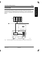
i
Vista Profibus Gateway Interface
Vista Profibus Gateway Interface
User’s Guide
Customer Product Manual
Part 321288A02
Nordson Corporation welcomes requests for information, comments and inquiries about its
products. General information about Nordson can be found on the Internet using the following
address: http://www.nordson.com.
Address all correspondence to:
Nordson Corporation
Attn: Customer Service
11475 Lakefield Drive
Duluth, GA 30097
Notice
This is a Nordson Corporation publication which is protected by copyright. Original copyright
date 1999. No part of this document may be photocopied, reproduced, or translated to another
language without the prior written consent of Nordson Corporation. The information contained in
this publication is subject to change without notice.
Trademarks
AccuJet, AquaGuard, Asymtek, Automove, Autotech, Blue Box, CF, CanWorks, Century, Clean
Coat, CleanSleeve, CleanSpray, Compumelt, Control Coat, Cross-Cut, Cyclo-Kinetic,
Dispensejet, DispenseMate, Durafiber, Durasystem, Easy Coat, Easymove Plus, Econo-Coat,
EPREG, ETI, Excel 2000, Flex-O-Coat, FlexiCoat, Flexi-Spray, Flow Sentry, Fluidmove,
Fluidshooter, FoamMelt, FoamMix, Helix, Horizon, Hose Mole, Hot Shot, Hot Stitch, Isocoil,
Isocore, Iso-Flo, JR, KB30, Little Squirt, Magnastatic, MEG, Meltex, MicroSet, Millenium, Mini
Squirt, Moist-Cure, Mountaingate, MultiScan, Nordson, OmniScan, Opticoat, Package of Values,
PluraFoam, Porous Coat, PowderGrid, Powderware, Pro-Flo, ProLink, Pro-Meter, Pro-Stream,
PRX, RBX, Ready Cost, Rhino, S. design stylized, Saturn, SC5, SCF, Select Charge, Select
Coat, Select Cure, Shur-Lok, Slautterback, Smart-Coat, Spray Squirt, Spraymelt, Super Squirt,
Sure-Bond, Sure Coat, System Sentry, Tela-Therm, Trends, Tribomatic, UniScan, UpTime,
Veritec, Versa-Coat, Versa-Screen, Versa-Spray, Watermark, and When you expect more. are
registered trademarks –r – of Nordson Corporation.
ATS, Auto-Flo, AutoScan, BetterBook, Chameleon, CanNeck, Check Mate, CPX, Control Weave,
Controlled Fiberization, EasyClean, Ebraid, Eclipse, Equi=Bead, Fillmaster, Gluie, Ink-Dot,
Kinetix, Maxima, MicroFin, Minimeter, Multifil, OptiMix, Pattern View, PluraMix, Primarc, Prism,
Process Sentry, PurTech, Pulse Spray, Seal Sentry, Select Series, Sensomatic, Shaftshield,
Spectral, Spectrum, Sure Brand, Swirl Coat, Vista, VistaView, Walcom, and 2 Rings (Design)
are trademarks – t – of Nordson Corporation.
E 2002 Nordson Corporation
All rights reserved
321288A02
Issued 3/02
41-PROFIBUS-MA-01
ii
Vista Profibus Gateway Interface
Table of Contents
Overview . . . . . . . . . . . . . . . . . . . . . . . . . . . . . . . . . . . . . . . . . . . . . . . . . . . . . . 1
About the Gateway Card . . . . . . . . . . . . . . . . . . . . . . . . . . . . . . . . . . . . . . . . . . . . . . . . . .
Software Version . . . . . . . . . . . . . . . . . . . . . . . . . . . . . . . . . . . . . . . . . . . . . . . . . . . . . . . . .
Hardware Requirements . . . . . . . . . . . . . . . . . . . . . . . . . . . . . . . . . . . . . . . . . . . . . . . . . .
Support Information . . . . . . . . . . . . . . . . . . . . . . . . . . . . . . . . . . . . . . . . . . . . . . . . . . . . . . .
2
2
2
2
Installation . . . . . . . . . . . . . . . . . . . . . . . . . . . . . . . . . . . . . . . . . . . . . . . . . . . . 3
Gateway Card Mounting Methods . . . . . . . . . . . . . . . . . . . . . . . . . . . . . . . . . . . . . . . . . . 3
Direct Method . . . . . . . . . . . . . . . . . . . . . . . . . . . . . . . . . . . . . . . . . . . . . . . . . . . . . . . . . 3
Offset Method . . . . . . . . . . . . . . . . . . . . . . . . . . . . . . . . . . . . . . . . . . . . . . . . . . . . . . . . . 4
Operation . . . . . . . . . . . . . . . . . . . . . . . . . . . . . . . . . . . . . . . . . . . . . . . . . . . . . 6
External Inputs . . . . . . . . . . . . . . . . . . . . . . . . . . . . . . . . . . . . . . . . . . . . . . . . . . . . . . . . . . . 6
Gateway Connectors . . . . . . . . . . . . . . . . . . . . . . . . . . . . . . . . . . . . . . . . . . . . . . . . . . . . . 6
Input Power Terminal Block (X3) . . . . . . . . . . . . . . . . . . . . . . . . . . . . . . . . . . . . . . . . . 6
Profibus Connector (X4) . . . . . . . . . . . . . . . . . . . . . . . . . . . . . . . . . . . . . . . . . . . . . . . . 7
Serial Port Connector (X1) . . . . . . . . . . . . . . . . . . . . . . . . . . . . . . . . . . . . . . . . . . . . . . 7
Vista Power Sense Connector (X7) . . . . . . . . . . . . . . . . . . . . . . . . . . . . . . . . . . . . . . 8
Communication Disable Connectors (X5) . . . . . . . . . . . . . . . . . . . . . . . . . . . . . . . . . 8
Gateway Indicators . . . . . . . . . . . . . . . . . . . . . . . . . . . . . . . . . . . . . . . . . . . . . . . . . . . . . . . 9
Profibus Data Structure . . . . . . . . . . . . . . . . . . . . . . . . . . . . . . . . . . . . . . . . . . . . . . . . . . . 9
Read and Write Command . . . . . . . . . . . . . . . . . . . . . . . . . . . . . . . . . . . . . . . . . . . . . 10
Toggle Flag . . . . . . . . . . . . . . . . . . . . . . . . . . . . . . . . . . . . . . . . . . . . . . . . . . . . . . . 10
Profibus Input Data . . . . . . . . . . . . . . . . . . . . . . . . . . . . . . . . . . . . . . . . . . . . . . . . . . . 11
Profibus Input . . . . . . . . . . . . . . . . . . . . . . . . . . . . . . . . . . . . . . . . . . . . . . . . . . . . . 11
Status Byte . . . . . . . . . . . . . . . . . . . . . . . . . . . . . . . . . . . . . . . . . . . . . . . . . . . . . . . 12
External Inputs . . . . . . . . . . . . . . . . . . . . . . . . . . . . . . . . . . . . . . . . . . . . . . . . . . . . 12
41-PROFIBUS-MA-01
321288A02
Issued 3/02
E 2002 Nordson Corporation
All rights reserved
iii
Vista Profibus Gateway Interface
Profibus Output Data . . . . . . . . . . . . . . . . . . . . . . . . . . . . . . . . . . . . . . . . . . . . . . . . . . 13
Profibus Output . . . . . . . . . . . . . . . . . . . . . . . . . . . . . . . . . . . . . . . . . . . . . . . . . . . . 13
Command Byte . . . . . . . . . . . . . . . . . . . . . . . . . . . . . . . . . . . . . . . . . . . . . . . . . . . . 14
Profibus Station Address . . . . . . . . . . . . . . . . . . . . . . . . . . . . . . . . . . . . . . . . . . . . . . 14
Programming Examples . . . . . . . . . . . . . . . . . . . . . . . . . . . . . . . . . . . . . . . . . . . . . . . . . . 15
Reading from Vista . . . . . . . . . . . . . . . . . . . . . . . . . . . . . . . . . . . . . . . . . . . . . . . . . . . . 15
Writing to Vista . . . . . . . . . . . . . . . . . . . . . . . . . . . . . . . . . . . . . . . . . . . . . . . . . . . . . . . 17
Appendix A . . . . . . . . . . . . . . . . . . . . . . . . . . . . . . . . . . . . . . . . . . . . . . . . . . . 19
Gateway Card Block Diagram . . . . . . . . . . . . . . . . . . . . . . . . . . . . . . . . . . . . . . . . . . . . . 19
Wiring Diagram . . . . . . . . . . . . . . . . . . . . . . . . . . . . . . . . . . . . . . . . . . . . . . . . . . . . . . . . . 20
Profibus Kit Parts List . . . . . . . . . . . . . . . . . . . . . . . . . . . . . . . . . . . . . . . . . . . . . . . . . . . . 22
Appendix B . . . . . . . . . . . . . . . . . . . . . . . . . . . . . . . . . . . . . . . . . . . . . . . . . . . 23
Vista Data Mapping . . . . . . . . . . . . . . . . . . . . . . . . . . . . . . . . . . . . . . . . . . . . . . . . . . . . . . 23
Appendix C . . . . . . . . . . . . . . . . . . . . . . . . . . . . . . . . . . . . . . . . . . . . . . . . . . . 32
GSD File for Profibus to ParvNet Gateway . . . . . . . . . . . . . . . . . . . . . . . . . . . . . . . . . . 32
Profibus DP Specific Features . . . . . . . . . . . . . . . . . . . . . . . . . . . . . . . . . . . . . . . . . . 32
Slave Specific Features . . . . . . . . . . . . . . . . . . . . . . . . . . . . . . . . . . . . . . . . . . . . . . . 33
E 2002 Nordson Corporation
All rights reserved
321288A02
Issued 3/02
41-PROFIBUS-MA-01
iv
41-PROFIBUS-MA-01
Vista Profibus Gateway Interface
321288A02
Issued 3/02
E 2002 Nordson Corporation
All rights reserved
Vista Pofibus Gateway Interface
Page 1
The Vista Profibus Gateway (or gateway card) interface enables fast information
exchange between the programmable logic controllers (PLC) and the linked 3000-Vista
applicator. The gateway card translates the Vista ParvNet protocol to the Profibus DP
protocol.
PLC
Profibus DP
3000 Applicator
Gateway
Card
ParvNet
Vista Controller
4131208A
Fig. 1 3000-Vista Applicator with the Profibus Gateway Card using the ParvNet Protocol
E 2002 Nordson Corporation
All rights reserved
321288A02
Issued 3/02
41-PROFIBUS-MA-01
Introduction
Overview
Page 2
Vista Profibus Gateway Interface
About the Gateway Card
The gateway card is a printed circuit board that is mounted in the Vista controller to
enable the data exchange. The gateway card supports Profibus baud rates of up to
12 Mbaud.
The gateway card operates from a 24 VDC power supply. A separate voltage source
allows the Profibus slave device to operate even when the power is removed from the
Vista controller.
Software Version
The Vista controller software version for the Vista controller must be 2.000 or higher for
the Vista data to match the tables in this manual. If the data does not match, install the
supplied software upgrade kit.
Hardware Requirements
For a complete list of hardware, refer to the Profibus Kit Parts List in Appendix A.
Support Information
Contact Nordson Technical Support for any technical support questions.
41-PROFIBUS-MA-01
321288A02
Issued 3/02
E 2002 Nordson Corporation
All rights reserved
Page 3
Vista Profibus Gateway Interface
Installation
Gateway Card Mounting Methods
The gateway card can be installed inside the Vista controller in one of two ways:
S direct
S offset
Direct Method
1. Disconnect and lock out electrical power to the Vista controller, including
I/O lines.
2. Open the electrical enclosure. Refer to the Vista controller manual.
3. Plug the gateway card directly into the Vista expansion slot.
+
Gateway Card
4131212A
Fig. 2 Mounting the Gateway Card Using Direct Method
E 2002 Nordson Corporation
All rights reserved
321288A02
Issued 3/02
41-PROFIBUS-MA-01
Installation
The gateway card can be mounted in the Vista controller with or without the pattern
controller option. However, it cannot be installed in Vista controllers that come with the
remote input/output (I/O) option card or an enhanced I/O option card.
Page 4
Vista Profibus Gateway Interface
Direct Method (contd).
4. Use the M3 X 10 screws and washers to mount the card support bracket on the
Vista controller frame.
5. Secure the gateway card with the screws to the support bracket. Tighten the
M4 X 12 screws to 2.03-2.26 N S m (18-20 in.-lb).
6. Connect the Profibus cable to the Vista controller (customer supplied).
NOTE: In the direct method, the RJ45 connector and the Vista power sense cable
are not needed because the serial port data is connected via the expansion
connectors.
7. Connect the 24 VDC supply to the gateway card.
8. Close and secure the electrical enclosure. Refer to your Vista controller manual.
9. Apply the 24 VDC supply to the gateway card, and turn on the Vista controller.
Offset Method
Use the offset method when a pattern controller card is installed in the Vista expansion
slots.
WARNING: There is a risk of equipment damage or personal injury. Make
sure that the electrical power to the Vista unit including input/output (I/O) lines
are disconnected and locked out.
1. Disconnect and lock out electrical power to the Vista controller, including I/O
lines.
2. Open the electrical enclosure. Refer to the Vista controller manual.
41-PROFIBUS-MA-01
321288A02
Issued 3/02
E 2002 Nordson Corporation
All rights reserved
Page 5
Vista Profibus Gateway Interface
3. Position the gateway card in front of the pattern controller card. Attach the two
cards with snap-in stand-offs and spacer.
NOTE: The spacer requires an M4 X 25 screw and an M4 lock washer to hold the
gateway card to the mounting bracket.
4. Plug the pattern controller card into the Vista expansion slot.
Gateway Card
Pattern Controller Card
4131211A
Fig. 3
Mounting the Gateway Card Using Offset Method
5. Plug the RJ45 cable into the RJ45 connector on the gateway card and the
pattern controller card.
6. Install the Vista power sense cable from X7 on the gateway card to J3 on the
Vista controller board.
NOTE: On J3, pin number 1 faces the inside of the circuit board.
7. Tighten the screw to 2.03-2.26 N S m (18-20 in.-lb).
8. Connect the 24 VDC supply to the gateway card.
9. Close and secure the electrical enclosure. Refer to the Vista controller manual.
10. Apply the 24 VDC supply to the gateway card, and turn on the Vista controller.
E 2002 Nordson Corporation
All rights reserved
321288A02
Issued 3/02
41-PROFIBUS-MA-01
Installation
+
Page 6
Vista Profibus Gateway Interface
Operation
External Inputs
Four general purpose external inputs are provided to read via Profibus. The external
inputs 1, 2, 3, and 4 can be driven with a 24 VDC PNP signal or a contact closure if the
opposite side of the contact is connected to 24 VDC.
Gateway Connectors
The following sections describe the connectors used on the gateway card and their
signals assignments.
Input Power Terminal Block (X3)
Terminal block X3 is where the input power is connected. It also contains the four
external inputs. The signal assignments for this connector are as follows:
Pin Number
Signal
1
24 VDC output (for use with external devices)
2
External input number1 (drive with PNP or 24 VDC sourcing signals)
3
24 VDC Common
4
24 VDC output (for use with external devices)
5
External input number 2 (drive with PNP or 24 VDC sourcing signals)
6
24 VDC Common
7
External input number 3
8
24VDC output (for use with external devices)
9
External input number 4 (drive with PNP or 24 VDC sourcing signals)
10
24VDC output (for use with external devices)
11
24 VDC input (connect external 24 VDC power source here)
12
24 VDC Common
41-PROFIBUS-MA-01
321288A02
Issued 3/02
E 2002 Nordson Corporation
All rights reserved
Page 7
Vista Profibus Gateway Interface
Profibus Connector (X4)
X4 is a female 9-pin D-shell connector that conforms to standard Profibus DP wiring
methods. An isolated 5 VDC supply is provided for use with termination networks. The
signals connected to it are as follows:
Pin Number
Signal
1
Earth ground
2
Not connected
3
Profibus + signal
4
Not connected
5
5 V Common (isolated)
6
+5 VDC output (isolated)
7
Not connected
8
Profibus – signal
9
Not connected
The RJ45 serial port connector (X1) is used when the gateway card is used in
conjunction with a pattern controller option card. The signal assignment of the serial
port connector are as follows:
Pin Number
Signal
6
Circuit common
7
RS232 data from Vista
8
RS232 data to Vista
E 2002 Nordson Corporation
All rights reserved
321288A02
Issued 3/02
41-PROFIBUS-MA-01
Operation
Serial Port Connector (X1)
Page 8
Vista Profibus Gateway Interface
Vista Power Sense Connector (X7)
The gateway card can monitor the power ON/OFF status of the Vista controller by
reading the 5 V supply on the Vista controller. When the gateway card is remotely
mounted, the Vista 5 V supply must be cabled to the gateway card via the X7 connector.
When the gateway card is directly mounted, the cabling is via the card edge connector
and no additional cable is required.
When the X7 connector is used, cable it to the J3 connector on the Vista controller
board. Pin number 4 of the X7 should connect to the pin closest to the edge of the PCA
on J3. The signal assignment of the power sense connector are as follows:
NOTE: The J3 connector is not polarized.
Pin Number
Signal
1
+ 5 VDC from Vista
2
Not used
3
Not used
4
Circuit common
Communications Disable Connector (X5)
The two-pin header X5 connector can be used to disable communications between the
Vista controller and the gateway card.
Connect pin number 1 to pin number 2 with a jumper or a cable, in order to disable
communications between the Vista controller and the gateway.
Pin Number
Signal
1
Disable communications signal
2
Circuit common
41-PROFIBUS-MA-01
321288A02
Issued 3/02
E 2002 Nordson Corporation
All rights reserved
Page 9
Vista Profibus Gateway Interface
Gateway Indicators
Indicator
Function
Power Indicator or DS4
Illuminates when power is applied to the gateway.
Profibus Active or DS8
Illuminates when the gateway is in the Profibus data exchange
mode of operation.
Profibus Ready or DS5
Illuminates whenever the gateway checks for input or output
data to or from the Profibus master.
Profibus Data Input or DS6
Toggles every time Profibus input data is written to the SPC3
ASIC.
Profibus Fault or DS7
Illuminates when a fault is detected in the Profibus
microprocessor circuitry.
ParvNet Ready or DS1
Illuminates when the ParvNet interface is in the operational
state.
ParvNet Data Active or DS2
Illuminates when the ParvNet port sends or receives data from
the Vista controller.
ParvNet Fault or DS3
Illuminates when a fault is detected in the ParvNet
microprocessor circuitry.
Eight input bytes and eight output bytes are transmitted on the Profibus network to and
from the gateway. The command/response data structure allows a Profibus master to
access any word in the Vista data map.
Due to the slow data rates (2400 baud) between the gateway card and the Vista
controller, there could be a noticeable delay between the time data is written by the
master until the time it reaches the Vista controller. This delay could be a maximum of
several seconds. Therefore the actual time between writing to the Profibus gateway and
when that data is actually applied in the Vista controller is different.
E 2002 Nordson Corporation
All rights reserved
321288A02
Issued 3/02
41-PROFIBUS-MA-01
Operation
Profibus Data Structure
Page 10
Vista Profibus Gateway Interface
Read and Write Command
The Profibus master requests to read or write a 16-bit data value with a single
command.
Toggle Flag
A toggle flag is used to determine when a command is complete. The address specified
in the output buffer corresponds to the address shown in the Vista Data Mapping
section, Appendix B.
S For read commands, the toggle flag changes state every time new data is sent
back to the Profibus master.
S For write commands, the toggle flag changes state when new data is written to
the Profibus gateway.
The toggle flag indicates when the gateway is ready to receive another write command
to the Vista. Once the toggle flag changes, that data is guaranteed to be sent to the
Vista controller and another data packet can be sent to the Profibus gateway. If another
command is sent to the gateway before the toggle flag changes state, it is possible that
one of the commands will be ignored.
41-PROFIBUS-MA-01
321288A02
Issued 3/02
E 2002 Nordson Corporation
All rights reserved
Page 11
Vista Profibus Gateway Interface
Profibus Input Data
The tables below describe the format of the data received by the Profibus master. The
gateway always returns the most current value from the address specified in the
Profibus output data. The toggle bit changes state every time a new data value is read
from the gateway.
Profibus Input
Profibus Input
Buffer Address
Byte Name
Function
Status byte
Contains the status information from the
controller outlined below.
1
Address
The address of the specific data returned from
the ParvNet map.
2
Data at address
The byte of data read from the address
specified above.
3
Data at address +1
The byte of data read from the address
specified above +1.
4
External inputs
The four external inputs (active high)
5
Not used
6
Not used
7
Not used
E 2002 Nordson Corporation
All rights reserved
321288A02
Issued 3/02
41-PROFIBUS-MA-01
Operation
0
Page 12
Vista Profibus Gateway Interface
Status Byte
Data Bit
Function
D0
Vista Power: 0 - OFF, 1 - ON
D1
Ready: 0 - Vista controller not ready, 1 - Vista controller ready
D2
Warning: 0 - no warnings, 1 - warning present
D3
Fault: 0 - no faults, 1 - faults present
D4
Heater status: 0 - heaters off, 1 - heaters on
D5
Pump status: 0 - pump off, 1 - pump on
D6
Standby status: 0 - unit in standby, 1 - unit not in standby
D7
Toggle flag: Changes state when a command is completed
External Inputs
Data Bit
Function
D0
External input 1
D1
External input 2
D2
External input 3
D3
External input 4
D4
Not used
D5
Not used
D6
Not used
D7
Not used
41-PROFIBUS-MA-01
321288A02
Issued 3/02
E 2002 Nordson Corporation
All rights reserved
Page 13
Vista Profibus Gateway Interface
Profibus Output Data
The tables below describe the format of the data output from the Profibus master to the
Vista controller. After the data is written from the Profibus master to the gateway, it
stays active until it is re-written or power is removed from the gateway.
Profibus Output
Profibus Input
Buffer Address
Byte Name
Function
Command Byte
Contains the command information to the unit
outlined below.
1
Address
The address of the ParvNet location being
modified.
2
Data (at Address)
The byte of the data written to the address
specified above.
3
Data (at Address +1)
The byte of the data written to the address
specified above + 1.
4
Not used
5
Not used
6
Not used
7
Not used
E 2002 Nordson Corporation
All rights reserved
Operation
0
321288A02
Issued 3/02
41-PROFIBUS-MA-01
Page 14
Vista Profibus Gateway Interface
Command Byte
Data Bit
Function
D0
Heaters On/Off:
0 - OFF, 1 - ON
D1
Pump On/Off:
0 – OFF, 1 – ON
D2
Standby On/Off:
0 – ON, 1 – OFF
D3
Read/Write Command:
0 - Read Only: the data specified at buffer addresses 2 and 3 are not
written to the Vista.
1 - Write Only: the data specified at buffer addresses 2 and 3 is written
to the address specified in the output buffer address 1.
D4
Not used
D5
Not used
D6
Not used
D7
Not used
Profibus Station Address
The Profibus address of the gateway is set with two decimal rotary switches on the
gateway card:
S S1 (least significant digit)
S S2 (most significant digit)
NOTE: The station address can be set to any value between 0 and 99.
41-PROFIBUS-MA-01
321288A02
Issued 3/02
E 2002 Nordson Corporation
All rights reserved
Page 15
Vista Profibus Gateway Interface
Programming Examples
When the 3000-Vista is powered ON, load all Vista parameters from the Profibus master
to the gateway in order to put the Vista controller into a known state. The parameters
remain in the gateway until power is removed or they are over written with new data. If
the Vista controller is power cycled, the parameters will be restored to the Vista
controller by the gateway.
During operation, the Command Byte in the Profibus output data buffer is continuously
written to the gateway by the Profibus master. Therefore, make sure that the Command
Byte always contains the proper values for Heater On/Off, Pump On/Off, Heater Mode
On/Off, and Write bit.
Reading from Vista
To read the actual temperature of the tank, load the Profibus output buffer with the
following data:
Address
0
07
Assumes heaters and pump are on and not in
standby mode.
1
A0
Address to read from tank temperature location
(in HEX)
2
XX
Reading only
3
XX
Reading only
4
XX
Not used
5
XX
Not used
6
XX
Not used
7
XX
Not used
E 2002 Nordson Corporation
All rights reserved
Data Comments
321288A02
Issued 3/02
41-PROFIBUS-MA-01
Operation
Output Buffer
Page 16
Vista Profibus Gateway Interface
Reading from Vista (contd).
After the data is loaded, the input buffer is monitored and waits until the toggle bit
changes state. After it changes state, the input buffer will look something like this:
Input Buffer
Address
Data
0
73 or F3
1
A0
Address that was read from tank temperature
location (in HEX)
2
01
Most significant byte of tank temperature
(149_ C [300_ F], in HEX)
3
2C
Least significant byte of tank temperature
(149_ C [300_ F], in HEX)
4
00
External inputs. Assumes all OFF.
5
XX
Not used
6
XX
Not used
7
XX
Not used
41-PROFIBUS-MA-01
Comments
Will be one of two values, depending on state of
toggle bit. Assumes no faults or warnings and that
the controller is READY.
321288A02
Issued 3/02
E 2002 Nordson Corporation
All rights reserved
Page 17
Vista Profibus Gateway Interface
Writing to Vista
To set gun number 1’s setpoint of to 135_ C (275_ F), load the Profibus output buffer
with the following data:
Output Buffer
Address
Data
Comments
0
0D
Assumes heaters are ON, but the pump is OFF, and
not in Standby Mode.
CAUTION!: Do not set the write bit until the address
is ready to prevent writes to the wrong location.
34
Address writes to gun number 1 setpoint location
(in HEX)
2
01
Most significant byte of gun number 1 setpoint
(in HEX)
3
13
Most significant byte of gun number 1 setpoint
(in HEX)
4
XX
Not used
5
XX
Not used
6
XX
Not used
7
XX
Not used
E 2002 Nordson Corporation
All rights reserved
321288A02
Issued 3/02
Operation
1
41-PROFIBUS-MA-01
Page 18
Vista Profibus Gateway Interface
Writing to Vista (contd).
After the data is loaded, input buffer is monitored and it waits until the toggle bit changes
state. After it changes, the Profibus master can safely write another set of data to the
Vista controller. When the toggle bit changes, the input buffer will look something like
this:
Output Buffer
Address
Data
Comments
0
0D
Will be one of two values, depending on state of toggle
bit. Assumes no faults or warnings and that the controller
is READY.
1
34
Address that was written to gun number 1
2
01
Most significant byte of gun number 1 setpoint (in HEX)
3
13
Most significant byte of gun number 1 setpoint (in HEX)
4
XX
External inputs. Assumes all OFF except for the Vista
power status.
5
XX
Not used
6
XX
Not used
7
XX
Not used
41-PROFIBUS-MA-01
321288A02
Issued 3/02
E 2002 Nordson Corporation
All rights reserved
Page 19
Vista Profibus Gateway Interface
Appendix A
Gateway Card Block Diagram
Profibus
Profibus
Interface
SIEMENS
SPC3
ASIC
Opto-isolators
5 VDC ISOLATED
Profibus
68HC11
System
Power
Supply
5 VDC
24 VDC
5 VDC
24 VDC
5 VDC
Opto-isolators
ParvNet
68HC11
System
4
4
24 VDC PNP
or Switch Inputs
Dual Port
RAM
RS232
Disable
Profibus Switch
Vista Controller
4131207A
Fig. 4 Gateway Card Block Diagram
Appendix A, B, & C
E 2002 Nordson Corporation
All rights reserved
321288A02
Issued 3/02
41-PROFIBUS-MA-01
Page 20
Vista Profibus Gateway Interface
Wiring Diagram
The gateway card provides an electrically isolated Profibus interface that conforms to
the Profibus DP standard. The wiring diagrams show the Vista Profibus Gateway
electrical interface.
+5V
U12
HCPL7710
8
7
VDD2
5
1
VDD
2
NC
6
ASIC_RXD
3
NC
GND1
GND2
4
GND
5V_COM
VCC
U13
HCPL7710
VCC
R87
10K
1/16W
1%
1
VDD1
VDD2
2
ASIC_TXD
3
1
NC
+5V
8
7
6
1
5
3
NC
4
VCC
R69
402
1/8W
1%
GND1
GND2
GND
5V_COM
U17
2
R89
1K
1/16W
1%
+5V
VCC
2
+5V
VCC
4
R71
1K
1/6W
1%
VCC
8
7
ASIC_RTS
3
EN
6
GND 5
HCPL2601
5V_COM
4131209A
Fig. 5 Vista Profibus Gateway Electrical Interface (1 of 2)
41-PROFIBUS-MA-01
321288A02
Issued 3/02
E 2002 Nordson Corporation
All rights reserved
Page 21
Vista Profibus Gateway Interface
X4
+5V
1
R66
3
3
4
R
RE
DE
D
VCC
B
A
GND
1%
4
+5V
5
7
6
6
7
5
8
9
4
R70
R68
680
1/16W
1%
1/16W
C37
0.01uF
630v
10%
1
R67
1M
1/2W
5%
1
2
1/16W
8
11
2
1
CHASSIS
3
U14
75176B
1
10
2
100K
2
100K
1%
5V_COM
5V_COM
5V_COM
CHASSIS
5V_COM
4131213A
Fig. 6 Vista Profibus Gateway Electrical Interface (2 of 2)
Appendix A, B, & C
E 2002 Nordson Corporation
All rights reserved
321288A02
Issued 3/02
41-PROFIBUS-MA-01
Page 22
Vista Profibus Gateway Interface
Profibus Kit Parts List
The Profibus kit (P/N 1018 672) contains the following parts.
Part
Description
Quantity
321 288
Vista Profibus gateway interface user’s guide
1
------
Vista Profibus gateway card
1
302 202
Expansion/support bracket
1
277 857
RJ45 serial port cable
1
------
Vista Profibus power sense harness/cable
1
234 424
Vista software service kit, version 2.000 or higher
1
277 894
Flathead screwdriver
1
------
Unthreaded spacer, 0.5 in. long, nylon, 0.25 diameter, #8 scr
1
------
Snap-in standoff, 0.5 in., locking, nylon
2
982 097
Screw, pan, slotted, M4 X 25, ZN
1
982 971
Machine screw, hex, M4 X 12 ZN, with nylon patch
2
982 341
Screw, pan, recessed, M3 X 10, ZN
2
983 411
Washer, flat, narrow, M3, steel, ZN
2
983 400
Washer, lock, split, M3, steel, ZN
2
983 416
Washer, lock, internal teeth, M4, steel, ZN
1
41-PROFIBUS-MA-01
321288A02
Issued 3/02
E 2002 Nordson Corporation
All rights reserved
Page 23
Vista Profibus Gateway Interface
Appendix B
Vista Data Mapping
Address
Data
HEX
Read/Write
16.0
10.0
R/W
Heater On/Off
0=Heaters OFF
1=Heaters ON
16.1
10.1
R/W
Pump On/Off
0=Pump OFF
1=Pump ON
16.2
10.2
R/W
Heater control mode
0=standby mode
1=normal heat mode
16.3
10.3
R/W
Clear faults
Cleared on 0->1 edge
16.4
10.4
R/W
Sequential startup
enable
0=No sequential
heating
1=Sequential heating
16.5
10.5
R/W
Display heater
proportioning
0=Normal operation
1=Display heater
proportioning
16.6
10.6
R/W
Output contact select
number 1
0=Power Status
1= Warning
16.7
10.7
R/W
Output contact select
number 2
0=Pump Status
1= Ready
17.0
11.0
R/W
Auto start pump
0=Manual pump start
1=Auto pump start
17.1
11.1
R/W
Auto start heaters
0=Manual heaters start
1=Auto heaters start
17.2
11.2
R/W
Display units
0=F
1=C
17.3
11.3
R/W
Enable auto start clock
0 = ON
1 = OFF
17.4
11.4
R/W
Pattern controller
ON/OFF
0 = OFF
1 = ON
17.5
11.5
R/W
Auto start pattern
controller
0 = Manual start P.C.
1 = Auto start P.C.
E 2002 Nordson Corporation
All rights reserved
Description
321288A02
Issued 3/02
States
41-PROFIBUS-MA-01
Appendix A, B, & C
Decimal
Page 24
Vista Profibus Gateway Interface
Vista Data Mapping (contd)
Address
Data
Decimal
HEX
Read/Write
Description
States
17.6
11.6
R/W
Password enable
0=Password Disabled
1=Password Enabled
17.7
11.7
R/W
Remote pump/heater
enable
0=Remote input enables
heater.
1=Remote input enables
pump.
18.0-18.6
12.0-12.6
R/W
Factory test
Factory test only
18.7
12.7
R/W
Unit ready response on
remote zone enable
0=Unit stays ready when
cold zone enabled
remotely.
1=Unit loses ready when
cold zone enabled
remotely.
NOTE: To turn OFF a zone, set the setpoint to 99_ F (37_ C).
19-31
-
N/A
Not used
32
20
R/W
Day of the week
1-7
33
21
R/W
Hour of the day
0-23
34
22
R/W
Minute
0-59
35
23
R
Seconds (read only)
0-5936
36
24
R/W
Setpoint temperature,
tank
MSBYTE
37
25
R/W
Setpoint temperature,
tank
LSBYTE
38
26
R/W
Setpoint temperature,
grid
MSBYTE
39
27
R/W
Setpoint temperature,
grid
LSBYTE
40
28
R/W
Setpoint temperature,
hose 1
MSBYTE
41
29
R/W
Setpoint temperature,
hose 1
LSBYTE
41-PROFIBUS-MA-01
321288A02
Issued 3/02
E 2002 Nordson Corporation
All rights reserved
Page 25
Vista Profibus Gateway Interface
Address
Data
HEX
Read/Write
42
2A
R/W
Setpoint temperature, hose 2
MSBYTE
43
2B
R/W
Setpoint temperature, hose 2
LSBYTE
44
2C
R/W
Setpoint temperature, hose 3
MSBYTE
45
2D
R/W
Setpoint temperature, hose 3
LSBYTE
46
2E
R/W
Setpoint temperature, hose 4
MSBYTE
47
2F
R/W
Setpoint temperature, hose 4
LSBYTE
48
30
R/W
Setpoint temperature, hose 5
MSBYTE
49
31
R/W
Setpoint temperature, hose 5
LSBYTE
50
32
R/W
Setpoint temperature, hose 6
MSBYTE
51
33
R/W
Setpoint temperature, hose 6
LSBYTE
52
34
R/W
Setpoint temperature, gun 1
MSBYTE
53
35
R/W
Setpoint temperature, gun 1
LSBYTE
54
36
R/W
Setpoint temperature, gun 2
MSBYTE
55
37
R/W
Setpoint temperature, gun 2
LSBYTE
56
38
R/W
Setpoint temperature, gun 3
MSBYTE
57
39
R/W
Setpoint temperature, gun 3
LSBYTE
58
3A
R/W
Setpoint temperature, gun 4
MSBYTE
59
3B
R/W
Setpoint temperature, gun 4
LSBYTE
60
3C
R/W
Setpoint temperature, gun 5
MSBYTE
61
3D
R/W
Setpoint temperature, gun 5
LSBYTE
62
3E
R/W
Setpoint temperature, gun 6
MSBYTE
63
3F
R/W
Setpoint temperature, gun 6
LSBYTE
64
40
R/W
Standby temperature, tank
MSBYTE
65
41
R/W
Standby temperature, tank
LSBYTE
E 2002 Nordson Corporation
All rights reserved
Description
321288A02
Issued 3/02
States
41-PROFIBUS-MA-01
Appendix A, B, & C
Decimal
Page 26
Vista Profibus Gateway Interface
Vista Data Mapping (contd)
Address
Data
Decimal
HEX
Read/Write
66
42
R/W
Standby temperature, grid
MSBYTE
67
43
R/W
Standby temperature, grid
LSBYTE
68
44
R/W
Standby temperature, hose 1
MSBYTE
69
45
R/W
Standby temperature, hose 1
LSBYTE
70
46
R/W
Standby temperature, hose 2
MSBYTE
71
47
R/W
Standby temperature, hose 2
LSBYTE
72
48
R/W
Standby temperature, hose 3
MSBYTE
73
49
R/W
Standby temperature, hose 3
LSBYTE
74
4A
R/W
Standby temperature, hose 4
MSBYTE
75
4B
R/W
Standby temperature, hose 4
LSBYTE
76
4C
R/W
Standby temperature, hose 5
MSBYTE
77
4D
R/W
Standby temperature, hose 5
LSBYTE
78
4E
R/W
Standby temperature, hose 6
MSBYTE
79
4F
R/W
Standby temperature, hose 6
LSBYTE
80
50
R/W
Standby temperature, gun 1
MSBYTE
81
51
R/W
Standby temperature, gun 1
LSBYTE
82
52
R/W
Standby temperature, gun 2
MSBYTE
83
53
R/W
Standby temperature, gun 2
LSBYTE
84
54
R/W
Standby temperature, gun 3
MSBYTE
85
55
R/W
Standby temperature, gun 3
LSBYTE
86
56
R/W
Standby temperature, gun 4
MSBYTE
87
57
R/W
Standby temperature, gun 4
LSBYTE
88
58
R/W
Standby temperature, gun 5
MSBYTE
89
59
R/W
Standby temperature, gun 5
LSBYTE
41-PROFIBUS-MA-01
Description
321288A02
Issued 3/02
States
E 2002 Nordson Corporation
All rights reserved
Page 27
Vista Profibus Gateway Interface
Address
Data
HEX
Read/Write
90
5A
R/W
Standby temperature, gun 6
MSBYTE
91
5B
R/W
Standby temperature, gun 6
LSBYTE
92
5C
R/W
Temperature band, tank
93
5D
R/W
Temperature band, grid
94
5E
R/W
Temperature band, hose 1
95
5F
R/W
Temperature band, hose 2
96
60
R/W
Temperature band, hose 3
97
61
R/W
Temperature band, hose 4
98
62
R/W
Temperature band, hose 5
99
63
R/W
Temperature band, hose 6
100
64
R/W
Temperature band, gun 1
101
65
R/W
Temperature band, gun 2
102
66
R/W
Temperature band, gun 3
103
67
R/W
Temperature band, gun 4
104
68
R/W
Temperature band, gun 5
105
69
R/W
Temperature band, gun 6
106
6A
R/W
Over-temperature setpoint. all
zones
MSBYTE
107
6B
R/W
Over-temperature setpoint. all
zones
LSBYTE
108
6C
R/W
Auto standby time-out, minutes
MSBYTE
109
6D
R/W
Auto standby time-out, minutes
LSBYTE
110
6E
R/W
Auto shutdown time-out,
minutes
MSBYTE
E 2002 Nordson Corporation
All rights reserved
Description
321288A02
Issued 3/02
States
41-PROFIBUS-MA-01
Appendix A, B, & C
Decimal
Page 28
Vista Profibus Gateway Interface
Vista Data Mapping (contd)
Address
Data
Decimal
HEX
Read/Write
111
6F
R/W
112
70
113
71
114
72
115
Description
States
Auto shutdown time-out,
minutes
LSBYTE
Auto pump ON tank
temperature, MSBYTE
0=Start pump when
ready
Auto pump ON tank
temperature, LSBYTE
Non-zero=start
pump when tank
temperature equals
setting
R/W
Ready interlock delay
Minutes
73
R/W
Cps6 test command
Factory test only
116
74
R/W
Key press emulation
Factory test only
117
75
R/W
Key press emulation
Factory test only
118
76
R/W
Program time travels
State specific time
being set
119
77
R/W
Program time travels
Hours
120
78
R/W
Program time travels
Minutes
121-140
79-8C
N/A
Pattern controller pattern
definition
For future use
141-143
8D-8F
N/A
Not used
144.0
90.0
R
Ready status
0=Not Ready
1=Ready
144.1
90.1
R
Warning status
0=No Warnings
1=Warnings Present
144.2
90.2
R
Fault status
0=No Faults
1=Faults Present
144.3
90.3
R
Serial communications
enable
0=Disable Serial
Communications
1=Enable Serial
Communications
R/W
41-PROFIBUS-MA-01
321288A02
Issued 3/02
E 2002 Nordson Corporation
All rights reserved
Page 29
Vista Profibus Gateway Interface
Address
Data
HEX
Read/Write
144.4
90.4
R
Additional zones
1=6 Hose/gun unit
144.5
90.5
R
Grid installed
0=Grid not installed
1=Grid installed
144.6
90.6
R
I/O board installed
0=I/O board not
installed
1=I/O board installed
144.7
90.7
R
Test mode
0=Normal mode
1=Test mode active
145-159
91-9F
R
Factory test mode
Factory test control
160
A0
R
Actual temperature, tank
MSBYTE
161
A1
R
Actual temperature, tank
LSBYTE
162
A2
R
Actual temperature, grid
MSBYTE
163
A3
R
Actual temperature, grid
LSBYTE
164
A4
R
Actual temperature, hose 1
MSBYTE
165
A5
R
Actual temperature, hose 1
LSBYTE
166
A6
R
Actual temperature, hose 2
MSBYTE
167
A7
R
Actual temperature, hose 2
LSBYTE
168
A8
R
Actual temperature, hose 3
MSBYTE
169
A9
R
Actual temperature, hose 3
LSBYTE
170
AA
R
Actual temperature, hose 4
MSBYTE
171
AB
R
Actual temperature, hose 4
LSBYTE
172
AC
R
Actual temperature, hose 5
MSBYTE
173
AD
R
Actual temperature, hose 5
LSBYTE
174
AE
R
Actual temperature, hose 6
MSBYTE
175
AF
R
Actual temperature, hose 6
LSBYTE
E 2002 Nordson Corporation
All rights reserved
Description
321288A02
Issued 3/02
States
41-PROFIBUS-MA-01
Appendix A, B, & C
Decimal
Page 30
Vista Profibus Gateway Interface
Vista Data Mapping (contd)
Address
Data
Decimal
HEX
Read/Write
176
B0
R
Actual temperature, gun 1
MSBYTE
177
B1
R
Actual temperature, gun 1
LSBYTE
178
B2
R
Actual temperature, gun 2
MSBYTE
179
B3
R
Actual temperature, gun 2
LSBYTE
180
B4
R
Actual temperature, gun 3
MSBYTE
181
B5
R
Actual temperature, gun 3
LSBYTE
182
B6
R
Actual temperature, gun 4
MSBYTE
183
B7
R
Actual temperature, gun 4
LSBYTE
184
B8
R
Actual temperature, gun 5
MSBYTE
185
B9
R
Actual temperature, gun 5
LSBYTE
186
BA
R
Actual temperature, gun 6
MSBYTE
187
BB
R
Actual temperature, gun 6
LSBYTE
188
BC
R
System Mode
0=Sleep, 1=Startup,
2=Control, 3=Drowsy,
4=Going Down
189
BD
R
Minutes left in ready
interlock delay
Minutes
190
BE
R
Seconds left in ready
interlock delay
Seconds
191
BF
R
Jumper configuration
Factory test use
192
C0
R
Last key press
Factory test use
193
C1
R
Heater on-time, MSBYTE
Hours
194
C2
R
Heater on-time, Middle Byte
Hours
195
C3
R
Heater on-time, LSBYTE
Hours
196
C4
R
Heater on-time, minutes
Minutes
197
C5
R
Zone faults
For future use
198
C6
R
Zone faults
For future use
41-PROFIBUS-MA-01
Description
321288A02
Issued 3/02
States
E 2002 Nordson Corporation
All rights reserved
Page 31
Vista Profibus Gateway Interface
Address
Data
Decimal
HEX
Read/Write
Description
States
199
C7
R
Zone faults
For future use
200
C8
R
Zone faults
For future use
201
C9
R
Zone faults
For future use
202
CA
R
Zone faults
For future use
203
CB
R
Zone faults
For future use
204
CC
R
Zone faults
For future use
205
CD
R
Zone faults
For future use
206
CE
R
Zone faults
For future use
207
CF
R
Zone faults
For future use
Appendix A, B, & C
E 2002 Nordson Corporation
All rights reserved
321288A02
Issued 3/02
41-PROFIBUS-MA-01
Page 32
Vista Profibus Gateway Interface
Appendix C
GSD File for Profibus to ParvNet Gateway
Profibus DP Specific Features
Profibus Features
Specifications
Vendor_Name
Nordson
Model_Name
Vista_Gateway_8IO
Revision
B1
Ident_Number
0x05AD
Protocol_Ident
0
Station_Type
0
FMS_supp
0
Hardware_Release
B01
Software_Release
B01
9.6_supp
1
19.2_supp
1
93.75_supp
1
187.5_supp
1
500_supp
1
1.5M_supp
1
3M_supp
1
6M_supp
1
12M_supp
1
MaxTsdr_9.6
60
MaxTsdr_19.2
60
MaxTsdr_93.75
60
MaxTsdr_187.5
60
MaxTsdr_500
100
MaxTsdr_1.5M
150
MaxTsdr_3M
250
MaxTsdr_6M
450
41-PROFIBUS-MA-01
321288A02
Issued 3/02
E 2002 Nordson Corporation
All rights reserved
Page 33
Vista Profibus Gateway Interface
Profibus Features
Specifications
MaxTsdr_12M
800
Redundancy
1
Repeater_Ctrl_Sig
2
24V_Pins
2
Implementation_Type
SPC3
Slave family designation
(for configuration tool grouping)
Slave_Family
3
Icon bit map file Bitmap_Device
asi8026
Slave Specific Features
Slave Features
Specifications
0
Sync_Mode_supp
0
Auto_Baud_supp
1
Set_Slave_Add_supp
0
Min_Slave_Interval
1
Modular_Station
1 (May have different configurations)
Max_Module
1 (May have 1 operational configuration)
Max_Input_Len
195
Max_Output_Len
195
Max_Data_Len
390
Modul_Offset
255
Max_User_Prm_Data_Len
5
Fail_Safe
0
Max_Diag_Data_Len
16
ORDERNUMBER
1018672
Ext_User_Prm_Data_Const (0)
0x00, 0x00, 0x00, 0x00, 0x00
Module (End Module)
8 DI/8DO (0x17, 0x27)
E 2002 Nordson Corporation
All rights reserved
321288A02
Issued 3/02
41-PROFIBUS-MA-01
Appendix A, B, & C
Freeze_Mode_supp
Page 34
41-PROFIBUS-MA-01
Vista Profibus Gateway Interface
321288A02
Issued 3/02
E 2002 Nordson Corporation
All rights reserved
Nordson Corporation
11475 Lakefield Drive
Duluth, GA 30097-1511
Toll-free: 800-683-2314
www.nordson.com
© 2002 Nordson Corporation
All Rights Reserved.
All other products referred herein
are the property of their respective companies.
Manual Part Number: 321288A02