1
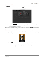
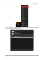
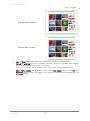
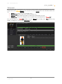
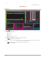
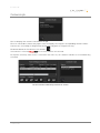
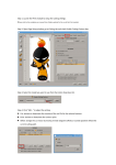
T A B L E O F C O N T E N T S Table of contents Table of contents _____________________________________________ 2 Introduction _________________________________________________ 3 The cut workflow _____________________________________________ 4 Contours _____________________________________________________________ 4 Vector files with embedded contours ____________________________________________ 4 Contours created in Compose __________________________________________________ 6 Check contours contained in a file ______________________________________________ 6 The print _____________________________________________________________ 8 Enable Cutting Contour _______________________________________________________ 8 Instant cutting ______________________________________________________________ 9 Print options ________________________________________________________________ 9 Contours __________________________________________________________________ 10 The Spooler __________________________________________________________ 12 VisualCUT __________________________________________________ 13 Overview ____________________________________________________________ Jobs queue __________________________________________________________ Cut queue information _______________________________________________________ The cut path _______________________________________________________________ Barcode search ____________________________________________________________ The preview __________________________________________________________ Cut selection_______________________________________________________________ Cutter connection _____________________________________________________ Settings _____________________________________________________________ Tools and settings and priority ___________________________________________ Add a cut tool ______________________________________________________________ Tools list management ______________________________________________________ Contours in job _______________________________________________________ Caldera 2014 Author: Diane Hoehlinger ©Caldera 2014 2 13 14 14 14 15 16 17 18 19 20 20 21 23 I N T R O D U C T I O N Introduction This document is the Caldera’s VisualCUT user manual. VisualCUT allows cut workflow management from files import into the RIP to print cut. VisualCUT has been designed for Graphtec, Summa, Mimaki, Mutoh and Roland… roll cutters. VisualCUT will automatically set up cut marks for the specific device it is driving and guide the machine along the documents embedded contours. VisualCUT even makes complex cutting easy thanks to the software’s ability to manage multiple contours in one file. Version This manual is based on the Caldera V10 version. ©Caldera 2014 3 T H E C U T W O R K F L O W The cut workflow Contours Vector files with embedded contours When loading a PS, EPS or PDF file, Fileman loads automatically all its vector paths during the preview process. Fileman displays, before the import, the embedded spot colors and vector files (see below). Each contour is linked to a spot color and has a particular name that is recognized by Fileman. Be careful: do not check the box placed in front of your contours. There will be included into the image so you won’t be able to use them for cutting anymore. By default, only contours beginning with “CutContour” are recognized as contours but others names can be set up to be recognized as well. Fileman: recognize others contour names Follow the steps below to add a new contour name to Fileman. 1. In Fileman’s main window, click on the Setup… button to open the setup window. 4 Caldera 2014 T H E C U T W O R K F L O W 2. Then click on the Edit Cut Contour list… button. The cut contour list appears. 3. There, use the button on side to manage your contour list: • New…: this button adds a contour to the list. • Delete: this button removes a contour from the list. • Edit: this button changes the contour name. If you type a name followed by a star “*”, every contour which begins with this name will be recognized by Fileman. Contour creation and edition window 5 Caldera 2014 T H E C U T W O R K F L O W Contours created in Compose The Compose module allows the user to create lines and objects for which cut contours can be created. Contours are defined in the compose setup: button Setup in the main window then tab Entities. Cut contours cannot be created on fonts, only on text blocs. Contours created in the Compose module can be defined as cutting paths. When different images are placed in a composition, their edges can also become cutting paths. Non-embedded vector contours When a contour is located in another file than the image itself, you can use Compose in order to make the contour to correspond to the image again. Check contours contained in a file You can check at any time if one of your images from your image bar contains cut files. • If your image is marked with a cutter it means that a cut contour has been recognized by Fileman during the import process. • Opens the Info module: o Double-click on the info icon on the tool bar then drag and drop the image in it. o Drag and drop the image in the tool bar info icon. o Select the image then make a right-click and click on About image. o Select the image then use the shortcut “Alt+a”. 6 Caldera 2014 T H E C U T W O R K F L O W Then select the Contours Tab. There you can see the list of the contours included in your image. If no line is written, no contour is linked to the image. 7 Caldera 2014 T H E C U T W O R K F L O W The print Some cut information have to be prepared in the Print module. Please refer to the complete user manual for the use of the Print module. All parameters are set up on the cutting tab of the page setup window. Enable Cutting Contour If the box Enable Cutting Contour is not checked, no cut can be associated to the job. • Cutter: choice of the job’s cutter. Use the arrow to display the menu and pick up the cutter. • Tools: opens a pop-up where parameters can be changed depending on the cutter model. Be careful: this button is only available for Grand cutters. • Configure…: updates the cutter list. It opens the following pop-up: The new and edit… buttons opens the cutter parameters pop-up while the delete button removes the cutter from the list. 8 Caldera 2014 T H E C U T W O R K F L O W These fields have to be filled to add a cutter: ∗ Name addition as it will appear in the cutter list. ∗ Choice of the model among those supported by Caldera. (The arrow displays the list.) ∗ Queue: display of the path to the directory where the cut files will be created. When a document is processed through the VisualCUT workflow, a cut job is generated at the end of the print process and sent to a local cutter queue. Each installed cutter has its own cut job queue, available in the corresponding CUT module. ∗ Hostname: the cutter address or network name used on the network to recognize the machine (IP address or localhost for example). Instant cutting If the printer allows it, this option sends the cut file to the printer so it will do the cut just after the print. Print options • Print registration marks: This option is required to cut a printed document. Specific marks are • Print bar code: This option prints a barcode on each edge of the document so the operator can added on the printed document to allow the positioning of the cutter device. • feed the cutter regardless of the orientation of the printed document. Then he has just to scan the barcode in front of him and the barcode scanner will automatically send the proper information to VisualCUT. o The QR Code functionality is for now usable only with Zünd Cut Center. Print identification number: This option print the identification number on each edge of the document so the operator can feed the cutter regardless of the print orientation. Then he has just to report the identification number into VisualCUT to find the proper job. 9 Caldera 2014 T H E C U T W O R K F L O W Contours • • Use: displays documents: all contours or cut contours only. Edit…: opens the following pop-up that acts on the selected contour: o Cut: activate or deactivate the creation of the cut file for the selected contour. o Print: activate or deactivate the contour print. o Offset: change the cut vector by moving it inside (negative offset) or outside (positive offset) the current cutting path. The values range from -10.00mm to +10.00mm. Be careful: do offset only for oblong contours. Using others shapes might trigger faults during the cut process. Offset examples. Original: 0.00mm offset. 10 Caldera 2014 T H E C U T W O R K F L O W Maximum offset: +10.00mm. Minimum offset: -10.00mm. • • Cut and Print: activate/deactivate the cut and the print for the selected contour. Cut all and print all: activate the cut and the print for all contours. The deactivation of one or the other must be done manually for each contour. By default, if the name of the contour begins with CutContour, it will be enable for cutting and disabled for printing. • Add a frame around: add an oblong contour around each image and/or around the entire document. These contours are hidden in the contours list above but will be displayed in the VisualCUT module. 11 Caldera 2014 T H E C U T W O R K F L O W The Spooler Once all print and cut parameters are correctly set up, the print can be launched. You can see its progression in the Caldera Spooler. You can also see, in the Cutting tab all the information about the cut: • Cutting: indicates if the cut is activated or not. • Target cutter: name of the cutter chosen to do the cut. • Barcode: barcode number printed on the document and linked to the job. • Cutting file: path of the cutting file that is automatically created and sent to VisualCUT. You can then launch the VisualCUT module from the Spooler by clicking on the Cut… button or by double-clicking on the cutter in the Applications list. 12 Caldera 2014 V I S U A L C U T VisualCUT Overview 1 2 5 3 6 4 The VisualCUT window can be divided into six parts. We will explicit each one of them separately in this second part of the document. 1. Jobs queue. 2. Preview. 3. Connection. 4. Settings. 5. Tools settings and priority. 6. Contours in job. Besides that, three buttons are available at the window’s button: - Cancel: cancel an action on the cutter. Be careful, if the information has already been sent to the cutter, the action cannot be canceled anymore. This button is principally dedicated to cancel the cut while the cutter is detecting the marks. - Cut: launch the job cut: launch the marks detection then the cut. Quit: close the window. Caldera 2014 13 V I S U A L C U T Jobs queue Cut queue information Every column is clickable so the jobs can be sorted by: - Job: sort by default, the name of the job determines its place in the queue. - Copies: sort by the number of copies done. The second number indicates the number of copies attended for the job while the first number indicates the number of copies done. If the first number is superior or equal to the attended copies, the job status moves from no to yes. - Done: sort by status, it indicates if the cut is over or not. Date: sort by date. Dimensions: sort by surface (multiplication of the dimensions displayed in the column). Barcode: sort by barcode (alphabetical order). Printer: sort by printer name. The sort can be upward or downward: the order can be reversed for every sort. Two buttons are also available to clean the list: - Clean done: remove all jobs which status is yes. - Delete: remove the selected job from the list. The cut path The cut Path is the location on the computer where the RIP solution will create the cut file after the print. This file contains all contours represented by vectors that will be used by the cutter. The path location is determined when the cutter is added to Caldera (see Enable cutting contour page 8). The user can change the path where VisualCUT will check for new jobs. The selection tool. Caldera 2014 14 button opens Caldera’s file V I S U A L C U T The second button: opens a pop-up that sets the jobs queue refresh time. In our example, every 10 second, the path is scanned by VisualCUT to check if new files have been created. If so, the corresponding jobs are added to the job queue. Barcode search When VisualCUT has been launched from the Caldera Spooler, the corresponding job is automatically selected in the jobs queue. A job can also be found by searching its barcode using the Input barcode field. The user enters the entire barcode and click on Enter . VisualCUT searches the job in the list and selects it. Caldera 2014 15 V I S U A L C U T The preview Here the user can see the jobs contours. The colors used depend on the tools set for each contour type (see Tools settings and priority). The scroll bar Opacity adjusts in the preview the image opacity to stand out the contours. Several opacities: maximum, medium and minimum. The two cut orientation buttons change the jobs orientation in the cutter. The modification is done with a 90° rotation to the left or the right depending on the arrow direction. Caldera 2014 16 V I S U A L C U T The three other orientations available for this job. The following actions belong to Caldera’s preview tool. So they can be used in the display or in the printing page set up as well. Zoom in, zoom out and scroll the image: actions available in every Caldera preview module to move into the preview. o Zoom in: while the Ctrl key is pressed, use the right mouse button or the mouse scroll up to zoom in. o Zoom out: while the Ctrl key is pressed, use the left mouse button or the mouse scroll down to zoom out. o Scroll the image: while the Ctrl key is pressed, keep the mouse scroll as well then move. Be careful, in opposition to the other preview tools, in this module, you cannot use the Alt + R combination that allows you to reset the preview. To get the default preview again, switch to another job then come back on the current one. Cut selection This tool allows the user to select on the image the copies which will be cut. If the selection frame touches a single part of the copy, its whole contours will be activated. In our example, only four copies are activated, the ones with the pale contours are not. The global frame is also activated because it is linked to each copy. The button at the bottom: Caldera 2014 selects all the job’s contours. 17 V I S U A L C U T Cutter connection The connection depends on the cutter type so the type has to be set up first. The buttons opens the advanced setup. Host and Port fields report information from the advanced setup. Status indicates if the cutter is connected and ready to be used. The detection is made automatically depending on the connection information that has been set up by the user: - Type: the cutter types available are: USB, Serial, RawIP and File. Hostname: output directory or IP address needed to connect the cutter. Host is only used for RawIP and File cutters, for the two others types fields below have to be filled. - Port: choice of the port used for the connection. The fields below are necessary only for Serial cutters. - Baud Rate: indication of the connection speed in baud. Parity: number of bits and type of parity (odd or even parity). Flow control: flow control type between: Xon/Xoff or Hardware. Please refer to the cutter user manual if you use a Serial one in order to fill the fields as right as possible. Caldera 2014 18 V I S U A L C U T Settings The settings define the positioning of the cutter. Depending on the model, all types are not available: - Single with marks: (formerly blind cut). The user places the blade on the first mark then launches the cut in VisualCUT. The cutter will detect the marks and then cut. - User points marks: (formerly semi-automatic). The user launches the cut then VisualCUT asks him to place the blade on the medium. After the user validation, marks will be detected and the cut will be done. - Automatic repeat/single: the user launches the cut then the cutter detects the marks and the barcode. It searches the barcode into the jobs queue then, when founded, the cutter launches automatically the cut process. The single mode does the operation once while the repeat mode, after the first job done, try to find a new one on the medium to do all jobs automatically. It stops when a barcode cannot be found on the medium and/or in the jobs queue. - Manual: in this mode the user has to place the blade precisely on the first mark before launching the cut process. - None: this mode is used for colored vinyl where no printed marks appeared on the medium. The user loads the medium in the cutter then launches the cut. The cutter step depends on the cutter model and can be adjusted in this part. The shapes sorting allows to choice the way contours will be considered. Non even placement is the path that is recommended for most of the cases. When you use Step&Repeat or when you enable panelling, choose Step-and-Repeat that reads the contours line by line. Panelling allows you, for very long jobs, to divide the cut processing into several panels. Accordingly to the driver you can set the panel length. For the others, panels are created using the marks placed on the job’s sides. The sheet off option tells the cutter to cut the medium at the end of the job. This is used to separate jobs in particular for an automatic repeat positioning on a roll. Caldera 2014 19 V I S U A L C U T Tools and settings and priority The tools determine which cut has to be done for a specific contour type. Add a cut tool The button adds a new tool to the list. It opens the pop-up: - Contour name: the name has to be related to the names used for contours. Indeed, the name will link the contour to its proper tool. A star “*” can be added only at the beginning or at the end of the name. The star can then be replaced by any string. Example: “CutContour*” fits for “CutContour”, “CutContourFrame” and “CutContourImage”. With the same logic, “*Contour” fits for “Contour” and “CutContour” but not for “CutContourFrame”. Be careful a name like “Cut*Contour” cannot be used, the star can only be place at the beginning or at the end of the string. The star is used to create generic contours tools. - Tool type: this type is device dependant. Example of tool types: o Kiss cutting: only the first layer of the medium is cut (for adhesive vinyl for example). o Dotted cutting o Cutting using a Laser to simulate the cut path… Please refer to the cutter user manual to choose the tool type you need. Caldera implements in its cutter driver all tools as specified by the manufacturer. - Speed: the speed range is device dependent. The tool head speed could largely affect the cutting quality. Caldera 2014 20 V I S U A L C U T - Force: pressure applied to the tool when cutting, its range is device dependent. Acceleration: acceleration of the tool head when cutting. Blade Offset: this option defines a little offset for each beginning and ending of a vector. Leave this parameter with its default value if the offset is not known. Dash force: pressure applied to the tool when cutting dashed lines. Please refer to the cutter user manual for each parameter above to choose the best values to use. The fields above may change accordingly to the cutter type. - Color: the color will be used in the preview to identify the tool. Cut Test: this button allows to check the current settings by sending a little sample cutting path to the device. A medium has to be loaded before performing this action. Tools list management The tools list organization is very important, the tools order will define their cut priority and when two tools fit for the same contour, which one will be used. Concretely VisualCUT does two operations: the allocation of the contours to the tools and the cut. Contours allocation For each contour, VisualCUT tests the tools from the top of the list to the bottom and stops when one can be used for the contour. So, if a generic tool is above a specific one, the contour will be linked to the generic one and not to the one that is dedicated to it. The Default tool Default is used when no other tool can be linked to a contour. Even if Default is at the top of the list, the algorithm will test it with the contour at the last place. About the cutting priority, Default is treated like any other tool so its cutting turn depends on its place in the list. Example: Tools list CutContourFrame Default CutContour_Dashed CutContour* CutContour_Kissed Contours CutContour CutContour_Dashed CutContour_Kissed CutContourFrame MyContour The contours will be linked to the tools following this: Tools CutContourFrame Default CutContourDashed CutContour* Contours linked CutContourFrame MonContour CutContour_Dashed CutContour et CutContour_Kissed We see that CutContour_Kissed is linked to CutContour* (generic) instead of the tool with its name because de specific tool was below in the tools list. Caldera 2014 21 V I S U A L C U T List management The tools list, in addition to the contour allocation, determines the cutting priority: the first tool of the list will cut first then cuts will be done following the list until the end. The buttons placed below the list organize it: - Tool addition (for further information see the previous page) - Tool edition. - Tool removal. Default tool cannot be deleted from the list, to ensure that a contour will always be linked to a tool. - The tool is moved place to the top. - The tool is moved one place to the bottom. Settings save The user is allowed to save the current tool list by using the following buttons. When used, the list is saved in a xml file that can be upload at any moment. - : list upload. - : list save. Creating saved lists built a database that can be used in production to quickly switch from one configuration to another. It saves time even when media are different and use others speed, force, etc. Caldera 2014 22 V I S U A L C U T Contours in job This list displays the contours contained in the job. The user can decide to launch only a part of the cuttings by selecting the corresponding contours names. Contours are selected by clicking on them one by one or by pack or using the Ctrl key. The button below the list deselects all contours. If no contour is selected, VisualCUT acts as if all contours are selected. To help the selection, when a tool is selected in the tools list, the contours linked to it are automatically activated. The tool selection automatically activates the contour. Caldera 2014 23