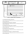
1
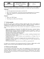
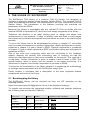
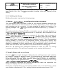
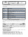
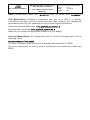
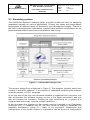
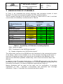
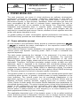
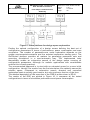
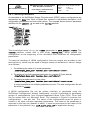
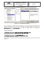
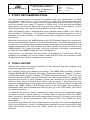
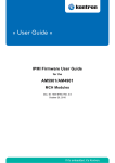
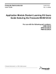
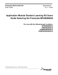
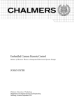
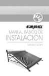
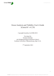
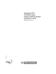
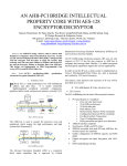
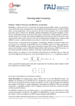
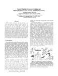
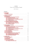
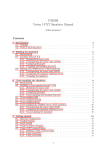
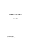
Title HW-SW SystemC Co-Simulation SoC Validation Platform Final Report and Executive Summary Contract No. 4200022968 by TU Braunschweig, Germany December 18, 2012 Document No.: IDA-SCSV-FR-001 HW-SW SystemC Co-Simulation SoC Validation Platform TU Braunschweig Final Report and Executive Summary Reference: Issue: Date: Page: IDA-SCSV-FR-001 V 0.1 11/10/12 1 Table of Contents 1 2 INTRODUCTION 4 1.1 P URPOSE AND S COPE 4 1.2 E XECUTIVE S UMMARY 4 1.3 R EVISIONS 4 1.4 ABBREVIATIONS AND A CRONYMS 4 1.5 O BJECTIVES OF THE STUDY 6 1.6 M ETHODOLOGY OF THE STUDY 6 1.6.1 P HASE 1: A NALYSIS & D ESIGN OF K EY IP S (WP 1000) 1.6.2 P HASE 2: VP D EVELOPMENT AND V ALIDATION (WP 2000) 6 10 1.7 ACHIEVEMENTS 13 1.8 R EFERENCE D OCUMENTS 13 THE USAGE OF SOCROCKET 15 2.1 B OOTSTRAPPING THE LIBRARY 2.1.1 B UILDING THE LIBRARY 15 17 2.2 W RITING NEW MODELS 18 2.3 S IMULATING SYSTEMS 21 3 VERIFICATION OF IP MODELS 24 4 POWER MODELING 26 4.1 P OWER ESTIMATION CONCEPT 26 4.2 ACQUIRING POWER VALUES 27 4.3 P OWER REPORTING 28 5 DESIGN SPACE EXPLORATION 31 6 LIBRARY IMPLEMENTATION ASPECTS 34 6.1 L IBRARY F OUNDATION 34 6.2 B ASE M ODELS 34 6.3 D ESIGNED IP M ODELS 36 6.4 DSE T OOLS & B UILD S YSTEM 36 6.4.2 C ONFIGURATION W IZARD 38 HW-SW SystemC Co-Simulation SoC Validation Platform TU Braunschweig Final Report and Executive Summary Reference: Issue: Date: Page: IDA-SCSV-FR-001 V 0.1 11/10/12 2 7 STUDY RECOMMENDATIONS 40 8 CONCLUSIONS 40 9 ACKNOWLEDGEMENTS 41 HW-SW SystemC Co-Simulation SoC Validation Platform TU Braunschweig Final Report and Executive Summary Reference: Issue: Date: Page: IDA-SCSV-FR-001 V 0.1 11/10/12 3 Table of Tables Table 1 - Revisions of this document .................................................................... 4 Table 2 – Abbreviations and Acronyms ................................................................ 5 Table 2 - List of IP models from development plan ............................................... 8 Table 3 - Supplementary IP models ..................................................................... 8 Table 4 - MiBench (selected) ............................................................................. 12 Table 6 - Software Dependencies (* optional) ..................................................... 16 Table 7 - Overview models/interfaces ................................................................ 18 Table 8 – Availability of IP Modules including Options ........................................ 24 Table 9 - List of IP models from development plan ............................................. 36 Table 10 - Supplementary IP models .................................................................. 36 HW-SW SystemC Co-Simulation SoC Validation Platform TU Braunschweig Final Report and Executive Summary Reference: Issue: Date: Page: IDA-SCSV-FR-001 V 0.1 11/10/12 4 1 INTRODUCTION 1.1 Purpose and Scope This document is the Final Report and Executive Summary of the SystemC Co-Simulation SoC Validation Platform (SoCRocket) 1.2 Executive Summary The goal of this project was to design the SoCRocket TLM Library, a common TLM 2.0 Library, but designed to simulate in particular designs of the Aeroflex Gaisler GRLib. The modeled TLM IP cores are modeled and verified TLM counterparts to the core components from the Gaisler library. The parameters in the platform leon3mp are matching the parameters from the GRLib. Moreover the library is extendable with any needed IP Core as shown with the external LEON3 or SpaceWire IP, which are now deeply integrated in the library. Therefore this platform is an ideal starting point to design and shape new architectures for new systems. It helps to identify risks and flaws in early stages and allows early software development and simulation as close to the real-thing as possible. All declared goals were reached including optional goals. Even with regards to having to work without test vectors. We had to debug low-level dependency components, for which we provided a patch set to fix the found issues. 1.3 Revisions The following table will be updated during the course of the project. Version Date Description 0.1 21/11/12 Initial document Table 1 - Revisions of this document 1.4 Abbreviations and Acronyms Acronym Description AMBA Advanced Microcontroller Bus Architecture HW-SW SystemC Co-Simulation SoC Validation Platform TU Braunschweig Final Report and Executive Summary Reference: Issue: Date: Page: IDA-SCSV-FR-001 V 0.1 11/10/12 5 Acronym Description API Application Programming Interface AXI Advanced eXtensible Interface AT Approximately Timed CA Cycle Accurate CAD Computer Aided Design DF Design Flow EDA Electronic Design Automation ESL Electronic System Level FPGA Field Programmable Gate Array GCC GNU Compiler Collection HW Hardware IDA Institute for Computer and Network Engineering at TU Braunschweig IP Intellectual Property LT Loosely Timed MPSoC Multi-Processor System-on-Chip OS Operating Systems OSCI Open SystemC Initiative RTEMS Real Time Executive for Multiprocessor Systems RTL Register Transfer Level SW Software SoC System-on-Chip SVN Subversion TLM Transaction Level Modeling VHDL VHSIC Hardware Description Language VHSIC Very High Speed Integrated Circuit VP Virtual Platform VPI Virtual Platform Infrastructure WP Work Package waf Waf Build System Table 2 – Abbreviations and Acronyms HW-SW SystemC Co-Simulation SoC Validation Platform TU Braunschweig Final Report and Executive Summary Reference: Issue: Date: Page: IDA-SCSV-FR-001 V 0.1 11/10/12 6 1.5 Objectives of the study The goal of this study is the development of a design flow (DF) for Virtual Platform (VP) implementation and validation. The study includes the modeling and the verification of Transaction Level Modeling (TLM) components and the design of a proof of concept VP. 1.6 Methodology of the study As shown in Figure 1 the project is comprised of two technical phases (WP1000 and WP2000), which are each split into several work packages (WP). At the end of each phase a review meeting was held to check the relevant achievements. In the following, we describe both phases and all WPs in detail. Figure 1 - Study logic 1.6.1 Phase 1: Analysis & Design of Key IPs (WP 1000) The objective of the first technical phase is to develop the necessary high-level SystemC models of existing RTL IP cores to produce a VP representative of a HW-SW SystemC Co-Simulation SoC Validation Platform TU Braunschweig Final Report and Executive Summary Reference: Issue: Date: Page: IDA-SCSV-FR-001 V 0.1 11/10/12 7 typical space SoC. The models are designed in a way, so that they can be reused and adapted to different platform configurations. 1.6.1.1 Task 1: Survey of tools and techniques (WP 1100) In Task 1, we have evaluated the required SystemC IPs and determined the best tools, techniques and methodologies to develop their high-level models according to the SystemC TLM 2.0 standard and validate them. The resulting work can be found in RD02. The methodology for modeling and validation of the TLM SystemC IP has been defined during the course of this task. Details are presented along with the associated work packages in sections: 1.6.1.2 High-Level Modeling of SystemC IPs (WP 1200) 1.6.1.3 Verification of TL Models (WP 1300) Subtasks: Review the existing specifications of the required IPs Refine a methodology for the development and validation of the required TLM SystemC IPs based on the state of the art ESL design Identify appropriate tools for virtual platform generation Outputs: Development plan IP requirement specification 1.6.1.2 Task 2: High-Level Modeling of SystemC IPs (WP 1200) In Task 2, we developed high-level models of the required IP blocks (Table 2) using SystemC language and adhering to the TLM 2.0 standard. Each IP block is available in both Loosely Timed and Approximately Timed TLM 2.0 coding styles. The models will come with appropriate scripts and test benches for compilation and verification of functionality. No. IP 1 AMBA AHB 2 Aeroflex Gaisler GRLIB MCTRL Memory Controller or equivalent 3 A memory model working with IP 2 4 A Harvard L1 cache (including support of cache coherence protocols, snooping and write invalidate) 5 A SPARCv8 MMU or equivalent 6 Aeroflex Gaisler GPTIMER General Purpose Timer Unit or equivalent HW-SW SystemC Co-Simulation SoC Validation Platform TU Braunschweig 7 Final Report and Executive Summary Reference: Issue: Date: Page: IDA-SCSV-FR-001 V 0.1 11/10/12 8 Aeroflex Gaisler IRQMP Interrupt Controller or equivalent Table 3 - List of IP models from development plan In addition to the components listed in the development plan as listed in Table 2 we delivered supplementary components listed in Table 3. No. IP 8 AMBA AHB to APB Bridge 9 Aeroflex Gaisler GRLIB APBUART 10 AHB System Profiler Table 4 - Supplementary IP models The AMBA bus models are designed with the GreenSocs AMBA Kit. The AMBA Kit contains a flexible bus model, which can be templated to act as APB, AHB or AXI. Which makes the system work instantly with AXI as well. However, not all features of the GRLIB implementation are supported. Particularly the plug & play extension was missing. We implemented this extension without compromising the AMBA Kit. Decisions on this topic were done in close interaction with ESA. For the modeling of the remaining IP, we followed the TLM methodology recommended by OSCI. Initiator and target peripherals are modeled as orthogonal components separated by well-defined interfaces. Each component is divided into a behavior section, a timing section, a power section, and a storage and synchronization section (Figure 2) closely interacting with each other. Figure 2 - TLM methodology For modeling the SystemC IP, we made use of the GreenReg open source framework for device and register modeling with TLM 2.0. Subtasks: Development and documentation of the required SystemC TLM IPs Development of test benches HW-SW SystemC Co-Simulation SoC Validation Platform TU Braunschweig Final Report and Executive Summary Reference: Issue: Date: Page: IDA-SCSV-FR-001 V 0.1 11/10/12 9 Functional model validation Outputs: SystemC TLM 2.0 model library of the required IPs Model User Manuals and Development Documents Compilation scripts, needed libraries, and test benches for each IP model 1.6.1.3 Task 3: Verification of TL Models (WP 1300) In Task 3, we evaluated the timing accuracy and simulation speed of each SystemC IP model and compare against the RTL implementation. The results of the verification process are reported in the IP Performance and Verification Document. Subtasks: Compare the developed SystemC IP models with their RTL counterparts to determine their timing accuracy Determine the simulation performance of each IP Update any eventual IP not meeting the requirements Outputs: IP Performance Document Updated SystemC Model Library 1.6.1.4 Task 4: Power Modeling (WP 1400) In Task 4, we augmented the SystemC IP library with accurate power models for the individual IP blocks (e.g. processor, cache, memory, etc.). In order to set up power models, we have synthesized and layouted the given RTL IP with Cadence Encounter using TSMC 90nm CMOS Technology as reference. The synthesized designs did undergo statistical power analysis to determine the average energy cost per activation for each block. To step up accuracy, the functionality was divided into events, which add up to the overall power budget during power simulation. These individually created power models were integrated into the SystemC TLM IP library models. Special care was taken that power modeling has only neglectable impact on the simulation speed of the SystemC IP. As indicated in Figure 2, the implementation of the power modeling functions are entirely independent from the functional behavior of the model. Subtasks: Perform logic synthesis, physical synthesis, and power analysis of RTL IP Add power modeling capabilities to the TLM interfaces HW-SW SystemC Co-Simulation SoC Validation Platform TU Braunschweig Final Report and Executive Summary Reference: Issue: Date: Page: IDA-SCSV-FR-001 V 0.1 11/10/12 10 Implement power models for the individual IP blocks Outputs: Updated SystemC Model Library 1.6.2 Phase 2: VP Development and Validation (WP 2000) The objectives of the second phase are the definition of the DF, the verification of the SystemC Model library in a proof of concept VP and the demonstration of a high-level DSE. 1.6.2.1 Task 5: Definition of the Design Flow (WP 2100) In Task 5, we have defined the DF and produced the VPI necessary to perform the communication, performance, and SW debugging analysis specified in Annex 1.2 of the RD01. A mechanism was developed to build such a VPI from the SystemC IP blocks developed in the previous tasks. The appropriate IP interconnection infrastructure is defined to allow the SystemC IP models to cooperate in a VP. This infrastructure supports transactors to connect models specified at different levels of abstraction. These transactors are written in SystemC and the interconnection methodology is outlined in the Interconnection Methodology Summary. The VPI: Allows the interconnection of TL and RTL models of the specified IPs Provides a tool for the system- and high-level design phases of an embedded system, allowing HW/SW co-design and early system validation Allows Integration, verification and debugging of hardware IPs Allows early software development on the target architecture: debugging (such as access to registers, linking to source code, breakpointing, etc.), monitoring, and profiling of application software Allows performance analysis: cycle count, transaction count, execution time, communication bandwidth and throughput Subtasks: Produce the VPI Determine the information that the VPI analysis tools need from the SystemC IP models Define an efficient mechanism to obtain such information during simulation Define the appropriate IP interconnection mechanisms Implement the appropriate transactors Produce a first iteration of the DF document Outputs: Updated SystemC IP Model Library / Transactor Library Design Flow User Manual Design Flow document: Interconnection infrastructure and analysis capability HW-SW SystemC Co-Simulation SoC Validation Platform TU Braunschweig Final Report and Executive Summary Reference: Issue: Date: Page: IDA-SCSV-FR-001 V 0.1 11/10/12 11 1.6.2.2 Task 6: Proof-of-concept VP Development (WP 2200) In Task 6, we defined and implemented the proof-of-concept VP (Figure 3) using all the SystemC IP models, the VPI and DF from the previous tasks. This VP runs software stimulating all the connected IP models. Figure 3 - Proof-of-concept VP hardware model The proof-of-concept VP contains a single CPU in a simple configuration. The software running on the VP can be any SPARC LEON3 executable. In our example we used bare-metal MiBench tests and in the high-level DSE demonstration an application containing RTEMS OS (Figure 4). Figure 4 - Proof-of-concept VP software model Appropriate test benches have been selected from the MiBench suite (Table 4). All C Code is going to be compiled with GCC and will be linked against the Gaisler bare-metal Newlib C library. HW-SW SystemC Co-Simulation SoC Validation Platform TU Braunschweig Final Report and Executive Summary Reference: Issue: Date: Page: IDA-SCSV-FR-001 V 0.1 11/10/12 12 Number Benchmark Application Domain 1 Quick Sort Automotive / Industrial 2 JPEG Consumer 3 Textsearch Office 4 Dijkstra Network 5 AES Security 6 FFT Telecommunication Table 5 - MiBench (selected) The proof-of-concept VP was implemented using the DF, which was updated with all the lessons and experience gained during the actual VP development. The VP was profiled and benchmarked, reporting its simulation performance in transactions per second, as specified in Annex A 1.3 of the RD01. The proof-of-concept VP: Demonstrates the application of the DF on a typical SoC, showing how it can be used for performance analysis and design trade-off Is a single distributable application that acts as a virtual development board, on which software can be run and performance can be estimated. Subtask: Interconnect all the IP models (both developed in Task 2 and ESA provided) using the VPI from Task 4 Develop and/or adapt the software to be run on the VP Benchmark the produced VP Update the DF based on lessons learned Outputs: The PoC VP package (SystemC source, build scripts, data files, testbenches, VP development document, VP user manual, etc.) PoC VP Definition, Interconnect and Performance Report Updated PoC Methodology 1.6.2.3 Task 7: High-Level DSE Demonstration (WP 2300) The proof-of-concept VP was used in conjunction with the VPI to demonstrate its use for high-level design space exploration (DSE). It was extended with multiple CPUs (up to 16). The VP ran a set of application benchmarks (Table 4) on top of RTEMS OS. Within these simulations, system performance and power dissipation was measured for different configurations of the platform. HW-SW SystemC Co-Simulation SoC Validation Platform TU Braunschweig Final Report and Executive Summary Reference: Issue: Date: Page: IDA-SCSV-FR-001 V 0.1 11/10/12 13 The main architectural parameter to be modified during the DSE is the number of CPUs in the system. As an additional parameter, the cache size may be modified. Subtasks: Port the application benchmarks to the PoC VP Run a set of simulations, varying the architectural parameters of the system Report the variations on system performance and the best and worst configuration Outputs: High-Level DSE Report Final Report and Executive Summary 1.7 Achievements All declared goals were reached including optional goals. Even with regards to having to work without test vectors. We had to debug low-level dependency components, for which we provided a patch set to fix the found issues. The following objectives were fully reached and acquired in agreement with the ESA: - - High-Level Modeling of SystemC IPs AMBA AHB Controller, Aeroflex Gaisler GRLIB MCTRL Memory Controller, A memory model, A Harvard L1 cache, A SPARCv8 MMU, Aeroflex Gaisler GPTIMER General Purpose Timer Unit and Aeroflex Gaisler IRQMP Interrupt Controller Verification of the mentioned TL Models Updating the SystemC Model Library with a power modeling framework and providing initial power values Implementing a first Virtual Platform and manufacture a Design Flow for creating such VPs Providing a proof-of-concept VP designed with the leon3mp platform in mind Providing software Tests for the Proof-of-concept VP, plus ensuring that RTEMS runs on the VP DSE Demonstration to show how to run a DSE on a generated VP In addition the modeling of the following SystemC IP Models: AMBA AHB to APB Bridge, Aeroflex Gaisler GRLIB APBUART and AHB System Profiler. 1.8 Reference Documents The documents listed below were used in the preparation of this document and contain additional information. In the event of conflict between the contents of this document and the contents of reference documents as listed below, this conflict shall be brought to the attention of the project management of the involved parties for clarification. HW-SW SystemC Co-Simulation SoC Validation Platform TU Braunschweig Final Report and Executive Summary Reference Document Number Reference: Issue: Date: Page: IDA-SCSV-FR-001 V 0.1 11/10/12 14 Document Title, Author RD01 TEC-EDM/2008.27/BG Statement of Work to ITT- AO/1-6025/09/NL/JK, ESA RD02 IDA-PPS-0309-2 HW-SW Co-Simulation SystemC SoC Validation Platform – Technical Proposal RD03 IDA-PPS 0309-3 HW-SW Co-Simulation SystemC SoC Validation Platform – Management Proposal RD04 IDA-SCSPV-PL-001 HW-SW SystemC Co-Simulation SoC Validation Platform – Development Plan RD05 IDA-SCSPV-UM-001 HW-SW SystemC Co-Simulation SoC Validation Platform – IP User Manual RD06 IDA-SCSV-PD-001 HW-SW SystemC Co-Simulation SoC Validation Platform – SystemC IP Verification and Performance Document RD07 IDA-SCSV-DF-010 HW-SW SystemC Co-Simulation SoC Validation Platform – Design Flow Report RD08 IDA-SCSV-PMR-004 HW-SW SystemC Co-Simulation SoC Validation Platform – Power Modeling Report RD09 IDA-SCSV-IMS-001 HW-SW SystemC Co-Simulation SoC Validation Platform – Interconnect Methodology Summary RD10 IDA-SCSV-DSE-001 HW-SW SystemC Co-Simulation SoC Validation Platform – High-Level DSE Report RD11 HW-SW SystemC Co-Simulation SoC Validation Platform – Analysis Capability Report HW-SW SystemC Co-Simulation SoC Validation Platform TU Braunschweig Final Report and Executive Summary Reference: Issue: Date: Page: IDA-SCSV-FR-001 V 0.1 11/10/12 15 2 THE USAGE OF SOCROCKET The SoCRocket TLM Library is a common TLM 2.0 Library, but designed to simulate in particular designs of the Aeroflex Gaisler GRLib. The modeled TLM IP cores are modeled and verified TLM counterparts to the core components from the Gaisler library. The parameters in the platform leon3mp are matching the parameters from the GRLib. Moreover the library is extendable with any needed IP Core as shown with the external LEON3 or SpaceWire IP, which are now deeply integrated in the library. Therefore this platform is an ideal starting point to design and shape new architectures for new systems. It helps to identify risks and flaws in early stages and allows early software development and simulation as close to the real-thing as possible. To do so the library has to be bootstrapped as shown in chapter 2.1 and either used for model development or platform exploration. Model development is shortly explained in chapter 2.2 and in detail in RD05. Platform exploration is introduced in chapter 2.3 and in detail explained in RD07 and further testing and refinement is explained in RD10. One of the most time consuming tasks was the verification of the hardware models. Besides the already time consuming task of verifying we had the misfortune that there were no test vector available for the project. This resulted in a long delay. Further information is given in chapter 3 and in detail in RD6. One special feature, which is woven into the models, is the power monitoring. It is introduced in chapter 4 and further information is provided in RD08. To show the full functionality of the library chapter 5 is explaining the methodology of a design space exploration with the SoCRocket design flow. Finally chapter 6 concludes with a description of the most important classes components and tools of the library. 2.1 Bootstrapping the library The SoCRocket Library can be checked out from our GIT repository at the following location: https://socrocket:[email protected]/git/socrocket.git To compile and simulate the comprised models, software and example platforms the following tools are required (Table 6): Tool / Lib Version Vendor Installation Path Variables Python (+PyQT4) >2.4 Python team GCC (x86) >4.1.0 GCC team On $PATH GCC/BCC (Sparc) >4.3.4 GCC team On $PATH On $PATH HW-SW SystemC Co-Simulation SoC Validation Platform TU Braunschweig Final Report and Executive Summary Reference: Issue: Date: Page: IDA-SCSV-FR-001 V 0.1 11/10/12 16 Binutils >2.19 GNU team On $PATH Doxygen* >=1.8.1 Doxygen On $PATH GCOV/LCOV* >4.1.0 GNU team On $PATH Boost >1_37_0 Boost team SystemC =2.2.x OSCI libelf 0.152 Elf Team TLM 2.0 2009-0715 OSCI GreenSocs 4.2.0 GreenSocs Ltd. $GREENSOCS_HOME – inst. root AMBASockets 1.0 Carbon Design Systems Inc $AMBA_HOME – installation root LUA >=5.1 Lua Comunity $LUA_HOME – installation root Modelsim* >6.0 Mentor Graphics On $PATH $BOOST_DIR - header path $BOOST_LIB - library path $SYSTEMC_HOME – installation root $ELF_HOME – installation root $TLM2_HOME – installation root $GRLIB_HOME – installation root GRLIB* 1.0.21 Aeroflex Gaisler $GRLIB_TECH – Path to compiled demo design: /designs/leon3-gr-xc3s-1500/modelsim Table 6 - Software Dependencies (* optional) Please make sure that all the software packages mentioned above are properly installed, before proceeding with building the library. Compiling software for the LEON ISS requires a SPARC compiler. We recommend using the GCC/BCC provided by Aeroflex Gaisler. It can be downloaded in different preconfigured packages depending on host system and software layout (e.g. bare-metal, rtems). http://www.gaisler.com/doc/libio/bcc.html The Mentor Modelsim simulator and the Aeroflex Gaisler GRLIB are required for SystemC/VHDL co-simulation. This feature can be optionally disabled (see 2.1.1). Gcov/Lcov and Doxygen are also optional components. The build system will not check for them. If the packages are not present, test coverage calculation and the generation of additional documentation are not possible. For the setup of the GreenSocs Software and the Carbon AMBA Sockets some additional instructions are given in RD05. Those are only intended to complement the documentation of the tools not to replace them. HW-SW SystemC Co-Simulation SoC Validation Platform TU Braunschweig Final Report and Executive Summary Reference: Issue: Date: Page: IDA-SCSV-FR-001 V 0.1 11/10/12 17 The build system shipped with the SoCRocket library is written in waf . It requires at least Python 2.4 to run. The waf executable is located in the root directory of the library. 2.1.1 Building the library Building the project requires the following steps: 1. Execute ./waf configure to configure the build environment The configuration step succeeds in case all the required software packages are available. Otherwise, it fails and shows the broken dependency. If so, the install path variable must be corrected. It is also possible to specify the location of a missing package. Use ./waf –h to see all the different options (e.g. --systemc, -tlm). As mentioned before, SystemC/VHDL co-simulation can be optionally disabled, in order to be independent of commercial tools or, eventually, save compilation time ( ./waf configure –nomodelsim ). Another important switch controls the verbosity of the output that is directed to stdout during simulation ( --verbosity=1..6) . Verbosity level one only display error messages. Level two includes warnings that are issued during simulation. Level three prints execution statistics and analysis reports. The recommended setting (default) is Level four. It additionally shows configuration reports and information about the progress of tests. The highest verbosity is bound to level 5. It displays a message for each state-change of a transaction, which tremendously slows down simulation and is therefore only recommended for debugging. (Add the –G switch to the configure command in case you plan on running coverage calculation. This will have a penalty on the system performance.) 2. Compile library and run unit tests Execute ./waf to compile all targets. Optionally, the –jN flag can be used to define to maximum number of parallel threads. If co-simulation is configured make sure you have enough licenses to execute N instances of Modelsim. As an alternative, you may select a specific target (test or library) for compilation. A list of targets can be generated with ./waf list . Selective compile is done using ./waf –targets=”comma,separated,list,of,targets” . After successful compilation the system automatically starts the respective unit test(s) and displays the result on the screen. Having the complete library up and running enables one to use the library to write new models as explained in 2.2 or making system simulations as shown in 2.3. HW-SW SystemC Co-Simulation SoC Validation Platform TU Braunschweig Final Report and Executive Summary Reference: Issue: Date: Page: IDA-SCSV-FR-001 V 0.1 11/10/12 18 2.2 Writing new models The SoCRocket library can be easily extended by creating own components. The existing simulation models provide examples for almost all possible combinations of bus interfaces: Model Bus interfaces leon iss CPU instruction master, CPU data master, Interrupt slave mmu_cache AHB master, CPU instruction slave, CPU data slave, Interrupt master, Snooping input ahbctrl AHB master (multi-socket), Snooping output apbctrl AHB slave, APB master ahbmem AHB slave mctrl AHB slave, APB slave socwire AHB master, Interrupt master gptimer APB slave, Interrupt master irqmp APB slave, Interrupt master (multi-socket), Interrupt slave (multi-socket) AHB slave (multi-socket), Table 7 - Overview models/interfaces To be integrated in the SoCRocket platform infrastructure, new models have to fulfill certain requirements. Most of them are encapsulated in a set of base classes. AHB Masters: All AHB master components must inherit from class AHBMaster . AHBMaster is derived from class AHBDevice and template class <BASE> . <BASE> can be sc_module , which is the default case, or any other child of sc_module . AHBDevice provides the interface for identification of the device in the system. At start_of_simulation the AHBCTRL reads the configuration records of all connected AHBDevices (Masters and Slaves) for building up its internal routing table (PNP records). The actual master socket, all related functionality, and state machines are encapsulated in class AHBMaster iself. The socket is defined as follows: amba_master_socket<32> ahb The socket can be accessed ./models/utils/ahbmaster.h ). via a set of interface functions Use the following function for reading from the master socket: void ahbread(uint32_t addr, unsigned char * data, uint32_t len); For writing data to the socket use: void ahbwrite(uint32_t addr, unsigned char * data, uint32_t len); (see HW-SW SystemC Co-Simulation SoC Validation Platform TU Braunschweig Final Report and Executive Summary Reference: Issue: Date: Page: IDA-SCSV-FR-001 V 0.1 11/10/12 19 Other functions are available for using debug transport, activating bus locking, obtaining cacheability information, handing over additional delay, or retrieving a response pointer. The master can be configured for LT and AT abstraction via constructor parameter ambaLayer . At LT abstraction read-data can be obtained by evaluating the data pointer right after the interface returns control (blocking). At AT abstraction communication is non-blocking. This means, in a read operation the data pointer will usually not be valid right after return from the interface call. That’s why a callback function is provided for notifying the user about a valid response: virtual void response_callback(tlm::tlm_generic_payload * trans) {}; The response_callback function is plain virtual and must be implemented by the user. AHB Slaves: AHB slave components must inherit from class AHBSlave . AHBSlave is derived from class AHBDevice and template class <BASE>. <BASE> can be sc_module , which is the default case, or any other child of sc_module . Modules implementing memory mapped registers should set <BASE> to gs::reg::gr_device (Greenreg Device). AHBDevice provides the interface for identification of the device in the system. At start_of_simulation the AHBCTRL reads the configuration records of all connected AHBDevices (Masters and Slaves) for building up its internal routing table (PNP records). The actual slave socket, all related functionality, and state machines are encapsulated in class AHBSlave itself. The socket is defined as follows: amba_slave_socket<32> ahb Communication with the user class is implemented using a callback function: virtual uint32_t exec_func(tlm::tlm_generic_payload &gp, sc_time &delay, bool debug = false) = 0; The slave can be configured for LT and AT abstraction via constructor parameter ambaLayer . At LT abstraction exec_func is directly called from b_transport , and at AT abstraction directly after receiving BEGIN_REQ . The user model is expected to load the delay pointer with a response delay value! The response delay is the number of wait-states required for delivering the data multiplied with clock cycle time. APB Slaves: All APB slaves must inherit from class APBDevice . Similar to AHBDevice the conveyed information is used to set up the routing table of the APBCtrl (PNP records). If the new device is supposed to have memory mapped registers, it must inherit from class gs::reg::gr_device . A small guide for modeling registers with GreenReg can be found in RD05. To enable the connection of the clock, the module should also inherit from class CLKDevice . class my_apbcomponent public CLKDevice : public gs::reg::gr_device, public APBDevice, HW-SW SystemC Co-Simulation SoC Validation Platform TU Braunschweig Final Report and Executive Summary Reference: Issue: Date: Page: IDA-SCSV-FR-001 V 0.1 11/10/12 20 Note: Classes that inherit from gr_device must not inherit from sc_module !! CPU Master/Slave: Building a component that acts as a CPU or is directly connected to the CPU does not require any base class. However, the transactions generated by the CPU are supposed to carry certain payload extensions. Instruction payload extensions: icio_payload_extension.h Data payload extensions: dcio_payload_extension.h Make sure to include the appropriate header/s in your design. Interrupt Master/Slave: All models that send or receive interrupts must use the following macro: SK_HAS_SIGNALS(class_name) For more information have a look at the SignalKit documentation in RD05. For more information on how to extend SoCRocket with additional models see RD05. HW-SW SystemC Co-Simulation SoC Validation Platform TU Braunschweig Final Report and Executive Summary Reference: Issue: Date: Page: IDA-SCSV-FR-001 V 0.1 11/10/12 21 2.3 Simulating systems The SoCRocket SystemC modeling library provides models and tools for designing embedded systems for various applications. Primary use cases are design-space explorations at different levels of abstraction and development stages. Thanks to the built-in reconfiguration mechanism, hardware and software components can be parameterized without superfluous compilations and linking. Figure 5 - SoCRocket Design Flow The general design flow is depicted in Figure 5. The designer typically starts from a piece of reference software. In the domain of embedded computing the software is usually written in C/C++ language. In the first step of the flow, the reference software is segmented into two parts: one that will become the software running on one of the target processors, and one that will become the hardware. Finding the right partitioning for a system is a complex task and usually requires multiple iterations. In the next step, the structure of the system must be captured in an Exploration Prototype (EP). To establish the EP, the user needs to explicitly instantiate the hardware architecture (using C++ code) to be simulated. Instantiation and configuration of any model subject to exploration can be bound to configuration HW-SW SystemC Co-Simulation SoC Validation Platform TU Braunschweig Final Report and Executive Summary Reference: Issue: Date: Page: IDA-SCSV-FR-001 V 0.1 11/10/12 22 parameters. These parameters are extracted from the design and stored in XML notation, along with default values, value ranges, and descriptions. The example in Figure 6 demonstrates this procedure. Here only one configuration parameter is specified ( nProcessors ). It will be initialized from the underlying GreenSoCs/GreenControl API at runtime (line 3). The EP creates and binds processors and caches in a loop iterating from 0 to nProcessors (lines 5-18). The library provides one predefined EP, the leon3mp , which will be used as an example throughout this document. More information about the structure and syntax of Exploration Prototypes is given in RD07 All parameters of all components are specified as GreenSocs parameters ( gs_params ) and, hence, can be easily modified at runtime. The time-consuming step of compiling and linking the platform needs to be carried out only once. The result is a configuration-independent simulator in form of an executable containing the GreenControl API. Figure 6 - Usage of reconfigurable parameters in Exploration Prototype (EP) In order to run the simulation, parameters extracted from the EP must be properly defined. Therefore, the VP provides a utility called the Configuration Wizard (CW). The CW parses the parameters extracted from the EP. In front-end mode, the user may define all settings in a graphical interface. The interface presents the parameters in a hierarchically organized way. Using front-end mode is helpful for first-time configuration. It is also possible to load and store configurations. For running larger explorations, it is more appropriate to vary the default settings in the XML parameter description and generated configurations by calling the wizard in terminal mode. The outputs of the CW are the SW runtime configuration and the HW runtime configuration. Next to defining parameters, the CW interprets the system’s memory map, generates linker scripts for software mapping, and creates a compilation script for automatic integration of the new system in the platform’s build environment. HW-SW SystemC Co-Simulation SoC Validation Platform TU Braunschweig Final Report and Executive Summary Reference: Issue: Date: Page: IDA-SCSV-FR-001 V 0.1 11/10/12 23 Running platform simulation still requires mapping the software portions of the design. The predefined EP provides software stacks for bare-metal simulation (with newlib ) and RTEMS OS . To avoid recompilation after each change in the memory map, we follow a two-stage approach: first the application program is compiled into a configuration- and position-independent executable file using a SPARC Compiler. Afterwards, the mkprom tool from Aeroflex Gaisler fills in all configurationspecific options, adds the boot code, and compresses the resulting application executable file into a ROM image or a separate platform depended prom image can be used to startup the platform. At simulation begin, the boot code initializes the registered components, decompresses the application file, and copies all data to the final memory locations. This flow is equivalent to the way hardware simulations are initialized in GRLIB, only that the VP can directly load binaries files. During simulation, the platform infrastructure gathers execution statistics. For this purpose every simulation model provides a set of performance counters. In the default configuration, the performance counters are written to the terminal after the end of the simulation. It is also possible to trace counters in log or waveform files, and to register handles for certain bounds and events. The analysis of the simulation results is the foundation for the verification of the design goals. The designer usually aims for requirements such as throughput and latency at the lowest possible cost. If the design goals are not met, configuration or partitioning must be optimized. This document only provides an example for using the analysis features of the platform. All available options are described in the Analysis Capability Report (RD11). HW-SW SystemC Co-Simulation SoC Validation Platform TU Braunschweig Final Report and Executive Summary Reference: Issue: Date: Page: IDA-SCSV-FR-001 V 0.1 11/10/12 24 3 VERIFICATION OF IP MODELS In Task 3, we evaluated the timing accuracy and simulation speed of each SystemC IP model and compared against the RTL implementation. The IP models required for the proof-of-concept VP, were built in Task 6, and their current state of availability is summarized in Table 8. Availability IP Model Reference Name AMBA Bus AMBA Bus Bridges SparcV8 MMU Cache + CCP IRQMP GPTMR MCTRL Embedded Memory SpaceWire SocWire CAN Bus Interface VHDL Description Available Available Available Available Available Available SystemC Model DEV DEV DEV DEV DEV DEV Test Vectors DEV DEV DEV DEV DEV DEV Available DNA Available Available DNA DEV DEV NI DEV DNA DEV DEV DEV DEV DNA Table 8 – Availability of IP Modules including Options DNA: "does not apply" DEV: "developed in the SoCRocket project" NI: “Needs integration into SoCRocket project” The official test vectors of the GRLIB are only contained in the commercial version of the library, which is not available to us. In the context of setting up the tests, it was tried to extract as many test vectors from the platform test benches of the open source GRLIB as possible. Additionally, sets of new test vectors had to be defined. In addition to the IP models listed above, a LEON3 ISS generation tool has been provided by ESA. Generation of and trials on a LEON3 ISS have already led to a successful simulation of a subset of MiBench applications (Table 4). Mentor Modelsim will be used as the main tool for verification. It provides capabilities for RTL / SystemC co-simulation and automatic test coverage calculation. Figure 7 illustrates the intended test bench setup. HW-SW SystemC Co-Simulation SoC Validation Platform TU Braunschweig Final Report and Executive Summary test vectors TLM Stimuli/Monitor Reference: Issue: Date: Page: test vectors TLM Stimuli/Monitor AMBA AMBA TLM IDA-SCSV-FR-001 V 0.1 11/10/12 25 Design Under Test TLM/RTL Adapter RTL Design Under Test Figure 7 - TLM module test setup The test vectors are wrapped inside a TLM 2.0 master module, which contains one process for sending stimuli to the module under test (MUT) and one process for monitoring and comparing simulation results. The TLM MUT can be directly connected to the sockets of the testbed. To obtain reference data from the RTL IP the same setup can be reused by inserting TLM/RTL adapters. An appropriate module was developed within this work packageWP1300. In case the timing accuracy does not met the requirements the models had to be modified or updated. During development, we kept simulation speed in mind. Fast simulation is crucial for the success of the process, although no particular requirement had been set. HW-SW SystemC Co-Simulation SoC Validation Platform TU Braunschweig Final Report and Executive Summary Reference: Issue: Date: Page: IDA-SCSV-FR-001 V 0.1 11/10/12 26 4 POWER MODELING The most prominent use cases of virtual platforms are software development, architecture exploration and system verification. Depending on the field of application the users are interested in high simulation speed, utilization and performance figures, or high accuracy. Nowadays, these use cases get more and more accompanied by the wish to estimate power consumption as early as possible and as high up as possible in the design flow. Especially modern embedded multi-processors have to consider power constraints. Particularly mobile, nomadic systems need to operate on given power budgets and are restricted to a maximum peak current. Hence, software for such systems should be written with power demands in mind. To enable trading off power consumption against performance and latency, the SoCRocket library provides an event based power-monitoring concept. 4.1 Power estimation concept All core models of the SoCRocket library provide a constructor parameter pow_mon . If pow_mon is enabled the power consumption of the respective module will be estimated during simulation runtime. Three different classes of power dissipation are supported: static power, dynamic internal power and dynamic switching power. Each of them is estimated and reported separately. The static power represents the ‘leakage’ of the component. It is more or less independent of the application running on the processor. For high-level approximations static power can be considered independent of the clock frequency. Static power linearly scales with silicon area and is strongly technology dependent. Therefore, SoCRocket simulation models contain at least one input parameter, which is supposed to be initialized with normalized leakage power information. The way of obtaining normalized leakage power is different for most components. For memories (e.g. SRAM, ROM) it is specified in pW/bit. The default settings included in the models are derived from a generic 90nm CMOS technology kit. The same accounts for the built-in dynamic power information. The dynamic power of a component is composed of an internal power portion and a switching power portion. In general, dynamic power is linearly dependent on the clock frequency. The internal power can be considered independent of the application running on the processor. It is caused by different effects such as registers (D-Flops) rewriting themself, toggling input pins or memory refresh cycles. Similar to static power the models contain dedicated input parameters for normalized dynamic power. The actual internal power is then being calculated with respect to the configuration at hand. Information about the normalized internal power of all simulation models can also be found in RD08. Normalization of internal power is always based on clock frequency or on clock frequency and a factor proportional to area (e.g. bits in memory). The application dependent part of the dynamic power is the so-called switching power. Switching power is dissipated if busses, pins or storage elements change value. Since power represents the average consumption of energy over time it is HW-SW SystemC Co-Simulation SoC Validation Platform TU Braunschweig Final Report and Executive Summary Reference: Issue: Date: Page: IDA-SCSV-FR-001 V 0.1 11/10/12 27 not an appropriate unit for event-based discrete measurement. Therefore, we rely on fixed normalized energy per access or energy per execution figures. The average switching power of a simulation can be obtained by counting the number of accesses, multiplying with a value representing the energy per access and dividing with the simulation time. Most library components, such as memories and busses, assign energy quotas to read/write operations, while e.g. the processor uses a fixed energy per instruction budget. 4.2 Acquiring power values To estimate the power consumption of the various models, all relevant GRLIB components have been synthetized using a generic design kit for 90nm CMOS technology. The design kit can be obtained from following location: http://www.synopsys.com/Community/UniversityProgram/Pages/Library.aspx It contains 90nm standard cells, memory models, a phase-locked loop, IO pads and various special components such as level shifters. Power estimation was done using Cadence RTL Compiler Version 10.10.100. The base for the normalized default power values given in RD08 is the LEON3MP reference design, which is also a part of the design kit. The default input power values have been obtained as follows: • Design synthesized to Gate-Level o The compile.rc script in the design library may be used to compile the sources. o Other scripts are available for setting up the technology libs (e.g. common_setup.tcl) o For information on how to elaborate and synthesize see the Cadence RTL Compiler User Manual o Components of the design annotated with statistical switching activity (default). • • Power Report generated with command: report power Normalized static power calculated by dividing static power with divisor linear to area: o e.g. normalized static power for AHBMEM (component ahbram0 / single-port SRAM): 𝑃𝑠𝑡𝑎𝑡𝑖𝑐𝑛𝑜𝑟𝑚 = • 𝑃𝑠𝑡𝑎𝑡𝑖𝑐 10400000 𝑝𝑊 = = 1269,53 𝑁𝑏𝑖𝑡𝑠 8192 𝑏𝑖𝑡 (with 𝑁𝑏𝑖𝑡𝑠 - size of memory in bits) Normalized internal power calculated by dividing internal power with divisor linear to area and clock frequency: o e.g. normalized internal power for GPTimer (logic): HW-SW SystemC Co-Simulation SoC Validation Platform TU Braunschweig Final Report and Executive Summary 𝑃𝑖𝑛𝑡𝑛𝑜𝑟𝑚 = Reference: Issue: Date: Page: IDA-SCSV-FR-001 V 0.1 11/10/12 28 𝑃𝑖𝑛𝑡 2,186 𝜇𝑊 = = 1,093𝑒 − 08 𝑛𝑡𝑖𝑚𝑒𝑟𝑠 ∗ 𝑓𝑐𝑙𝑘 2 ∗ 100 ∗ 106 𝐻𝑧 (with 𝑛𝑡𝑖𝑚𝑒𝑟 − 𝑛𝑢𝑚𝑏𝑒𝑟 𝑜𝑓 𝑝𝑎𝑟𝑎𝑙𝑙𝑒𝑙 𝑡𝑖𝑚𝑒𝑟𝑠) • Normalized switching energy is calculated by dividing energy per access with an area dependent divisor. The normalized energy per access is approximated by dividing the average switching power with the toggle rate and the clock frequency: o e.g. normalized access energy for component ahbram0 (single-port sram): 𝑒𝑎𝑐𝑐𝑒𝑠𝑠 = 𝑃𝑠𝑤𝑖𝑡𝑐ℎ 3,971 𝜇𝑊 = = 1,98𝑒 − 7 𝑡𝑟𝑎𝑡𝑒 ∗ 𝑓𝑐𝑘 0,2 ∗ 100 ∗ 106 𝐻𝑧 𝑒𝑎𝑐𝑐𝑒𝑠𝑠𝑛𝑜𝑟𝑚 = 𝑡𝑟𝑎𝑡𝑒 𝑤𝑖𝑑𝑡ℎ𝑏𝑖𝑡𝑠 𝑁𝑏𝑖𝑡𝑠 𝑒𝑎𝑐𝑐𝑒𝑠𝑠 1,98𝑒 − 7 𝜇𝐽 = = 7,57𝑒 − 13 𝑤𝑖𝑑𝑡ℎ𝑏𝑖𝑡𝑠 ∗ 𝑁𝑏𝑖𝑡𝑠 32 ∗ 8192 - toggle rate - width of memory - size of memory in bits 4.3 Power reporting The power modeling concept implemented in the SoCRocket library allows to monitor and report power consumption at different levels of accuracy. Given the presented interfaces it is easy to implement custom power reporting tools. An example implementation is given in: ./common/powermonitor.{h,cpp} This monitor is also integrated in the leon3mp platform. It can be configured to report the average power consumption of all modules in the system at a given instance in time (constructor parameter report_time ). If report_time is SC_ZERO_TIME the report will be generated at the end of the simulation ( end_of_simulation callback). To activate power reporting enable the p_report_power switch. The core functionality of the module is implemented in function gen_report . It operates in the following way: 1. Obtain pointer to GreenControl API: gs::cnf::cnf_api *mApi = gs::cnf::Gcnf_Api::get_ApiInstance(NULL) 2. Collect all registered parameters related to power consumption in std::vector power_list HW-SW SystemC Co-Simulation SoC Validation Platform TU Braunschweig Final Report and Executive Summary Reference: Issue: Date: Page: IDA-SCSV-FR-001 V 0.1 11/10/12 29 3. From power_list select all power output parameters belonging to the same instance 4. Print report for static, internal and switching power of the instance (if exists): e.g. mApi->getValue(std::string(get_model_name(models_list[0] + “.power.sta_power”), model_sta_power) 5. Accumulate power values for global statistics and remove instance from power_list 6. Continue with next model from power_list (3) 7. If power_list empty print global statistics Most of the models listed in RD05 report switching power. All of them contain a set of activity counters, e.g. for counting the number of reads or writes to a memory. These counters are implemented as externally visible configuration parameters, which means they can be modified/reset during simulation. Moreover, all models reporting switching power provide the parameter power_frame_starting_time . The latter can also be altered at runtime. At default power_frame_starting_time is initialized with SC_ZERO_TIME , which is the starting time of the simulation. The power reported by a model’s switching power output parameter always relates to the average switching power consumed in the time interval since power_frame_starting_time . Calculation of the average switching power is done inside the models using pre-read callback functions ( swi_power_cb ). This means, at every read access to a switching power output parameter, switching power is calculated from normalized per-access energy, number of accesses and ∆𝑇: 𝑝𝑠𝑤𝑖𝑡𝑐ℎ = (𝑒𝑝𝑒𝑟𝑎𝑐𝑐𝑒𝑠𝑠𝑛𝑜𝑟𝑚 ∗ 𝑛𝑎𝑐𝑐𝑒𝑠𝑠𝑒𝑠 )/(𝑇𝑛𝑜𝑤 − 𝑇𝑠𝑡𝑎𝑟𝑡 ) (𝑇𝑠𝑡𝑎𝑟𝑡 - power_frame_starting_time) Given this mechanism power profiles over time for whole applications can be generated at different granularity, by e.g. (Figure 8): • • • Continuously reading power outputs at regular intervals (as shown in RD08) After each read set power_frame_starting_time of observed modules to current simulation time After each read reset the activity counters HW-SW SystemC Co-Simulation SoC Validation Platform TU Braunschweig Final Report and Executive Summary Reference: Issue: Date: Page: IDA-SCSV-FR-001 V 0.1 11/10/12 30 Figure 8 - Example for custom power reporting Remark: More information about handling GreenControl parameters can be found in the SoCRocket Library User Manual (RD05). HW-SW SystemC Co-Simulation SoC Validation Platform TU Braunschweig Final Report and Executive Summary Reference: Issue: Date: Page: IDA-SCSV-FR-001 V 0.1 11/10/12 31 5 DESIGN SPACE EXPLORATION As an application for design space exploration we have selected lossless multispectral and hyper-spectral image compression as standardized by the Consultative Committee for Space Data Systems (CCSDS) in Standard #123. The algorithm is an example of the applications executed on the payload processors aboard most scientific satellites; as such systems are often resource constrained, the use of SoCRocket enables achieving an optimal configuration of the system with high performance while limiting the overall system’s cost in terms of siliconarea occupation and power consumption. As said above, the algorithm operates on hyperspectral images; these are threedimensional data sets, where two of the dimensions are spatial and the third is spectral. A hyperspectral image can be regarded as a stack of individual images of the same spatial scene, with each such image representing the scene viewed in a narrow portion of the electromagnetic spectrum. Overall, the algorithm is based on adaptive linear predictive compression using the sign algorithm for filter adaptation, with local mean estimation and subtraction. The prediction residual is then encoded using a sample-adaptive Golomb-Rice encoder. The implementation of the algorithm in C language has been provided by ESA. The code could not be used out-of-the-box, because it was not prepared for multithreaded execution. The code itself is in large parts dominated by data movements and bit-level optimizations. Naturally, it would be much better suited for a dedicated hardware implementation. This needs to be kept in mind, especially when looking at the simulation results. Nevertheless, the application makes an excellent demonstration case for design space exploration. It was decided to execute the code on top of RTEMS OS. The steps required for transforming the code into a flexible multi-processor implementation are explained in the following subsections. The base platform for the design space exploration described in this document is the leon3mp system, which can be found in the repository at following location: ./platforms/leon3mp Figure 9 shows the simplified structure of the system. The leon3mp VP consists of N processors, which are connected to an AMBA High-Performance Bus (AHB). Each of the processors has it’s own private instruction cache and data cache. The processors can also be configured to enclose memory management units as well as data localrams and instruction localrams . The shared AHB bus connects the CPUs to a memory controller. The memory controller can be configured for four different types of memory: IO , PROM , SRAM and SDRAM . The default configuration provides PROM + SDRAM . The APB-bridge connects the configuration registers of the MCTRL , the multiprocessor interrupt controller and the general purpose timer. Other components of the system are the AHBMEM , which is a simple SRAM device, the APBUART IP*, the SoCWire * bridge and the SpaceWire* bridge. * not in picture HW-SW SystemC Co-Simulation SoC Validation Platform TU Braunschweig Final Report and Executive Summary Reference: Issue: Date: Page: IDA-SCSV-FR-001 V 0.1 11/10/12 32 Figure 9 - Base platform for design space exploration Finding the optimal configuration of a design means defining the best set of configuration parameters in terms of performance, power consumption and area occupation. The number of parameter-sets under exploration depends on the system requirements/constraints and the selected exploration starting point. The SoCRocket platform provides all matters for generating parameter sets and executing simulations in a semi-automatic way. The implemented tools theoretically enable an exhaustive search of the design space covering all configuration parameters. Although for realistic applications with considerable runtime this is hardly practical. The recommended approach is to start with an educated guess for a sane initial configuration. Usually, the results from the first simulation runs radically narrow the solution space. Compared to exhaustive search, directed and controlled exploration leads to equally good results, but only requires a fraction of the time. The detailed description of the execution of the DSE is written down in RD10. The results of the DSE are plotted in Figure 10. It compares all the tested configurations in terms of simulation performance and power consumption. HW-SW SystemC Co-Simulation SoC Validation Platform TU Braunschweig Final Report and Executive Summary 1.4E+10 IDA-SCSV-FR-001 V 0.1 11/10/12 33 worst perform. (4) lowest power(2) 1.2E+10 Simulated Time in ns Reference: Issue: Date: Page: 1E+10 8E+09 6E+09 4E+09 2E+09 0 best trade-off (5) 0 5000 highest perf. (1) highest power (3) 10000 15000 Total Power in uW 20000 25000 Figure 10 - Summary: power vs. performance (1) Configuration with highest performance: 6x CPU, 4 data-cache sets, 8kB data-cache set size, 3 instruction-cache sets, 4kB instruction cache set size (2) Configuration with lowest power consumption: 2x CPU, 2 data-cache sets, 1kB data-cache set size, 1 instruction-cache set, 1kB instruction cache set size (3) Configuration with highest power consumption: 6x CPU, 4 data-cache sets, 8kB data-cache set size, 3 instruction-cache sets, 4kB instruction cache set size (4) Configuration with lowest performance: 2x CPU, 2 data-cache sets, 1kB data-cache set size, 1 instruction-cache set, 1kB instruction cache set size (5) Configuration with best power vs. performance trade-off: 2x CPU, 4 data-cache sets, 1kB data-cache set size, 3 instruction-cache sets, 4 kB instruction cache set size HW-SW SystemC Co-Simulation SoC Validation Platform TU Braunschweig Final Report and Executive Summary Reference: Issue: Date: Page: IDA-SCSV-FR-001 V 0.1 11/10/12 34 6 LIBRARY IMPLEMENTATION ASPECTS The simulation models of the library are developed in SystemC language and built on the OSCI TLM2.0 standard. Like any TL model they abstract from cycle-timed accuracy by modeling communication in form of function calls. Depending on the use case this can be done in many different ways. The general aim is to save simulation time by sacrificing a certain amount of timing accuracy. Moreover, TL simulations usually give the user a bigger amount of leeway, compared to RTL. Two major use cases are covered: software development and architecture exploration. Consequently, all IPs of the library support loosely timed (LT) and approximately timed (AT) abstraction. The abstraction layer is selected using constructor parameters. 6.1 Library Foundation In chapter 2.1 the bootstrapping of the library is explained. How to write models and use the generated platforms is explained as well. In addition we will explain here a little bit more in detail the most important classes and tools of the library. 6.2 Base Models In this section we will describe the base models ... listed will be the class, location and ... followed by a short description of its function.... oder so ähnlich Clock Device: class CLKDevice models/utils/clkdevice.* lib utils The class CLKDevice is used to consistently distribute clock/timing and reset amongst all IPs of the library. Devices that inherit from CLKDevice receive two SignalKit inputs: clk and rst . If the child requires reset behavior, it may implement the virtual function dorst() , which is triggered by the rst input. Moreover, CLKDevice provides a data member „clock_cycle“ , which can be used by the child to determine the clock period for delay calculations. The value of clock_cycle is set by connecting a sc_time SignalKit signal to the clk input or by calling one of the various set_clk functions of the class. AHB Device: class AHBDevice models/utils/ahbdevice.* lib utils All simulation models that are supposed to be connected to the TLM AHBCTRL must be derived from the class AHBDevice. Usually, this is indirectly done by inheriting from the AHB Master or AHB Slave classes (see below). The Aeroflex Gaisler AHBCTRL implements a Plug & Play mechanism, which relies on HW-SW SystemC Co-Simulation SoC Validation Platform TU Braunschweig Final Report and Executive Summary Reference: Issue: Date: Page: IDA-SCSV-FR-001 V 0.1 11/10/12 35 configuration information that is collected from the attached masters and slaves. AHBDevice models the respective configuration data records. The structure of these records is described in RD04. At start_of_simulation the TLM AHBCTRL iterates through all connected modules to retrieve AHB bar & mask and build up its internal routing table. AHB Master: class AHBMaster models/utils/ahbmaster.* lib utils Almost all models implementing an AHB master interface (except busses) are derived from class AHBMaster. AHBMaster is a convenience class providing an AHB master socket and implementations of various access functions for reading/writing data over the bus. AHBMaster inherits AHBDevice and can be configured for loosely timed (LT) or approximately timed (AT) level of abstraction. An overview about how to build own components based on AHBMaster is given in chapter 2.2. AHB Slave: class AHBSlave models/utils/ahbslave.* Almost all models implementing an AHB slave interface (except busses) are derived from class AHBSlave. AHBSlave is a convenience class providing an AHB slave socket and callback functions for hooking up with the behaviour of user models. AHBSlave inherits AHBDevice and can be configured for loosely timed (LT) or approximately timed (AT) level of abstraction. An overview about how to build own components based on AHBSlave is given in chapter 2.2. APB Device: class APBDevice models/utils/apbdevice.* lib utils All simulation models that are supposed to be connected to the TLM APBCTRL must be derived from class APBDevice. Similar to the concept of AHBDevice, the child inherits Plug & Play configuration records representing its device type and address. At start_of_simulation the APBCTRL iterates through the connected slaves collecting all APB bar and mask settings for building up its routing table. Modules, like the MCTRL, which posses an AHB as well as an APB interface must be derived from AHBDevice and APBDevice. HW-SW SystemC Co-Simulation SoC Validation Platform TU Braunschweig Final Report and Executive Summary Reference: Issue: Date: Page: IDA-SCSV-FR-001 V 0.1 11/10/12 36 Memory Device: class MEMDevice models/utils/memdevice.* lib utils The class MEMDevice is the base class of all memories to be connected to the MCTRL. The library provides a Generic Memory, which implements the given interface. The included functions are required to determine the features of the attached component for correct access and delay calculation. 6.3 Designed IP Models One oft the goals were to develop several TLM IP models. Table 9 is a list of all needed IP models. In addition supplementary IP models where designed to make the platform simulation more accurate and usable (Table 10). No. IP 1 AMBA AHB 2 Aeroflex Gaisler GRLIB MCTRL Memory Controller or equivalent 3 A memory model working with IP 2 4 A Harvard L1 cache (including support of cache coherence protocols, snooping and write invalidate) 5 A SPARCv8 MMU or equivalent 6 Aeroflex Gaisler GPTIMER General Purpose Timer Unit or equivalent 7 Aeroflex Gaisler IRQMP Interrupt Controller or equivalent Table 9 - List of IP models from development plan No. IP 8 AMBA AHB to APB Bridge 9 Aeroflex Gaisler GRLIB APBUART 10 AHB System Profiler Table 10 - Supplementary IP models 6.4 DSE Tools & Build System This chapter gives an overview over the additional tools provided by the library. The tools are mostly used to change and modify platform parameters. Starting with an introduction in platform parameters it will be explained how to use the DSE system tools and then the generator wizard and direct scriptable tools to modify the configuration JSON files. HW-SW SystemC Co-Simulation SoC Validation Platform TU Braunschweig Final Report and Executive Summary Reference: Issue: Date: Page: IDA-SCSV-FR-001 V 0.1 11/10/12 37 6.4.1.1 Defining Parameters As described in the SoCRocket Design Flow document (RD07) system configurations are represented by json files. Each of these files contains a hierarchical description of all configuration parameters and their initial values. The example below shows a parameter definition for the ahbctrl IP , as used in the leon3mp platform: "conf": { "ahbctrl": { "cfgaddr": 4080, "cfgmask": 4080, "defmast": 0, "fixbrst": false, "fpnpen": true, "ioaddr": 4095, "ioen": true, "iomask": 4095, "mcheck": true, "rrobin": false, "split": false } The hierarchical name of e.g. the rrobin parameter is conf.ahbctrl.rrobin . The leon3mp platform comes with a LUA script ( config.lua ), which parses the configuration at the beginning of the simulation and initializes all configuration parameters. To ease the handling of JSON configuration files two scripts are provided in the tools directory, which may be used to set/get names of attributes or values. Usage is as follows: 1. For obtaining the value of a certain parameter: ./tools/get_json_attr leon3mp.json conf.ahbctrl.rrobin 2. For getting a list of all parameter/value pair for a certain IP (here ahbctrl): ./tools/get_json_attr leon3mp.json conf.ahbctrl 3. For setting a parameter to a new value: ./tools/set_json_attr leon3mp.json conf.ahbctrl.rrobin=true It is also possible to set multiple parameters at once. The new configuration file will be written to stdout . A JSON configuration file can be written manually or generated using the SoCRocket Configuration Wizard. Additionally, a script is provided for generating groups of configurations from Comma-Separated-Values Files (CSV). Such files can be written with e.g. Microsoft Excel. The example in Figure 9 contains four configurations – one per line. The name of the configuration must be given in column A. All other columns represent parameters. The name of the parameter is expected in the first row (header of table). It must be equivalent to the name of the parameter in the platform (e.g. conf.mctrl.prom.elf for application binary). HW-SW SystemC Co-Simulation SoC Validation Platform TU Braunschweig Final Report and Executive Summary Reference: Issue: Date: Page: IDA-SCSV-FR-001 V 0.1 11/10/12 38 Figure 11 - Spreadsheet for generating json configurations To generate json configuration files for each of the configurations in the spreadsheet use the following command: ./tools/csv2json leon3mp.json configurations.csv The default configuration file of the leon3mp platform ( leon3mp.json ) is used as a template. All parameters that are found in the CSV file will be assigned to new values. 6.4.1.2 Running Simulation All configurations that shall be explored in one step should be located in the benchmark SW directory. For the example of the hyperspectral compressor this path is: ./software/rtems/ccsds123-mp-v2 The directory contains a Makefile for controlling the exploration. The Makefile compiles the application code, applies target specific settings and starts the simulation(s). Software can be compiled with following command: make targets Boot-code will be generated and linked automatically. The application is not completely platform independent. Especially, the number of CPUs needs to be known at linking time (parameter expected by mkprom ). Therefore, this step will generate multiple binaries for systems with one, two, four and six CPUs. If the software is compiled and the JSON configuration file(s) are available, the simulation can be started. This can be done in multiple possible ways. 6.4.2 Configuration Wizard The SoCRocket configuration wizard can be used to generate and reconfigure system simulations. The tool can be started with following command: ./waf generate The wizard offers a dialog, which allows the user to select a template and a configuration, or create a new configuration for an existing template. All parameters of the template will be displayed in an input mask. HW-SW SystemC Co-Simulation SoC Validation Platform TU Braunschweig Final Report and Executive Summary Reference: Issue: Date: Page: IDA-SCSV-FR-001 V 0.1 11/10/12 39 Figure 12 - Configuration Wizard The configurations created by the wizard can be copied and then modified with a simple text editor, due to the fact that they are pure JSON files. The tools get_json_attr and set_json_attr can help to modify them for example in automated design space explorations. Change Attributes: ./tools/set_json_attr templates/leon3mp.singlecore.json conf.system.ncpu=2 > templates/leon3.dualcore.json To navigate through a file use get_json_attr : ./tools/get_json_attr templates/leon3mp.json conf (Will show all attributes in conf) More detailed information about the SoCRocket configuration wizard can be found in RD10. HW-SW SystemC Co-Simulation SoC Validation Platform TU Braunschweig Final Report and Executive Summary Reference: Issue: Date: Page: IDA-SCSV-FR-001 V 0.1 11/10/12 40 7 STUDY RECOMMENDATIONS First of al we recommend to extend the platform with more components. To keep the platform useful and in use it is crucial to extend the library and add more components. This will cover more cases so that many teams in different fields of work can benefit from using TL Models in DSEs. Only a rich and well-developed base library can provide these services and the results of this project, as the SoCRocket library, can just be the foundation for such a library. While the platform was in development some changes where made to the state of the art tools in TLM Design. The SystemC 2.3 library is published and fixes a lot of problems of the 2.2 version. It would be more than suitable to switch over to the new library. Moreover substituting the AMBASockets with OCPSockets should be considered. During the development phase of the SoCRocket library, the OCP partnership was collecting TLM components and base libraries. GreenSocs and the AmbaKit is now deeply integrated in the OCP libraries and OCP sockets are the successor to the AMBASockets. So it should be take very little effort and is strongly recommended to substitute the AMBASockets with the OCPSockets. Furthermore it is important that the library is debugged by further use. As any software this software will not be without flaws and only the use in different kinds of application from different people can solve that. 8 CONCLUSIONS After all, the project has proven successful. Every objective has been acquired and every goal has been reached. All 7 SystemC High-Level Models are working. The AMBA AHB Controller, Aeroflex Gaisler GRLIB MCTRL Memory Controller, A memory model, A Harvard L1 cache, A SPARCv8 MMU, Aeroflex Gaisler GPTIMER General Purpose Timer Unit and Aeroflex Gaisler IRQMP Interrupt Controller are tested and verified in single test benches and proven to work together in other test benches or the LEON3MP VP platform with various software tests. More over to design a fully functional and timing accurate platform it was required to extend the library by one more optional model, the AMBA AHB to APB Bridge, which is as well tested and verified in standalone tests and combinational tests as well as in the DSE setup. See RD05 for more information. To measure the platform power consumption power vectors are integrated in each of these 8 models. And a basic set of power data is extracted from the TSMC 90nm process to annotate and verify these power vectors. The output can be used to measure the power consumption while doing a DSE. See RD08 for more information. To perform such DSEs we’ve provided a proof-of-concept VP model, designed with the leon3mp platform in mind. Its defaults are modeled as close as possible to the leon3-xilinx-ml509 design from the GRlib, which we used to cross verify DSE behavior. HW-SW SystemC Co-Simulation SoC Validation Platform TU Braunschweig Final Report and Executive Summary Reference: Issue: Date: Page: IDA-SCSV-FR-001 V 0.1 11/10/12 41 Moreover we’ve developed multiple tools and a design flow to support creation and usage of such VPs with the SoCRocket library. The tools are usable for cli automation, but not limited to and even include a graphical wizard to change configurations of the defined platform. The design flow, which defines how to create and use such platforms, is discussed in detail in RD07. Information on how to use the tools can be found in RD10. To test the VP we’ve used various bare metal tests, which are included in the SoCRcoket library and build with the entire library. Plus we’ve executed various operating systems on top of is like FreeRTOS and RTEMS. Two RTEMS targets are included in the library. See RD10 to utilize them. In RD10 RTEMS is used in our DSE Demonstration to facilitate the DSE with operating systems in the VPs we have added another model to the library which is a TL Model of the Aeroflex Gaisler GRLIB APBUART. Moreover to meter points of interest in a DSE and to end a DSE in a way that the simulation results are shown we have developed an AHB System Profiler, which is directly interacting with the SystemC simulation environment from within the SPARC software. The project took longer time then planned which was caused by a number of unforeseen circumstances. First the AMBA-Kit library was promised to be GPL, which did not materialize. Hence parts of the library had to be re-designed by ourselves. This larger effort was not originally planned for. The second problem that caused delays was the unavailability of test vectors for WP1300. As a consequence we had to verify IP blocks without test-vectores, some of them even without full specification. To conclude this results the DSE Report has shown the use of TLM platforms can drastically reduce the time of optimizing the platform architecture to optimally meet the demands of a specific application. So the development of such a platform was long overdue and this project has the potential to be the first stone in a big component library drastically reducing the simulation time. 9 ACKNOWLEDGEMENTS We take this opportunity to express a deep sense of gratitude to the ESA especially Luca Fossati, for his cordial support, valuable feedback, support, information and guidance, which helped us in completing this task through various stages and difficulties.