1
Embedded Data Systems
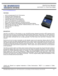
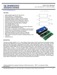
OW-SERVER-ENET-2
OW-SERVER-ENET-2 Operation Manual
Rev 1.1
Embedded Data Systems, LLC; 2019 Fortune Dr., Lawrenceburg, KY 40342; Phone/Fax 502-859-5490
EN-USERMAN OW-SERVER 1.1
2.29.12
1 / 38
Table of Contents
OW-SERVER-ENET-2 Operation Manual ................................................................................................... 1 Table of Contents ....................................................................................................................................... 2 Introduction................................................................................................................................................ 4 How this manual is organized: .................................................................................................................. 4 Quick Start Guide .......................................................................................................................................... 5 Interface ......................................................................................................................................................... 6 Physical ...................................................................................................................................................... 6 USB............................................................................................................................................................ 6 Web ............................................................................................................................................................ 6 Programmatic ............................................................................................................................................. 7 Configuration ................................................................................................................................................. 8 WEB Setup ................................................................................................................................................ 9 1-Wire Setup ............................................................................................................................................ 10 POST Client Setup ................................................................................................................................... 11 USB.......................................................................................................................................................... 11 Web Access ................................................................................................................................................. 13 1-Wire Device Status Overview .............................................................................................................. 13 Connected Devices .............................................................................................................................. 14 1-Wire Device Details ............................................................................................................................. 15 Communications .................................................................................................................................. 15 Connected Devices .............................................................................................................................. 17 Integration .................................................................................................................................................... 18 HTTP ....................................................................................................................................................... 18 Retrieving XML File ........................................................................................................................... 18 Writing Data to 1-Wire Devices .......................................................................................................... 19 Firmware Upgrading ............................................................................................................................ 19 SNMP (Simple Network Management Protocol) .................................................................................... 20 edsEnterprise Branch ........................................................................................................................... 20 dTrap Branch ....................................................................................................................................... 20 Telnet ................................................................................................................................................... 23 UDP ......................................................................................................................................................... 24 Low Level 1-Wire Interface .................................................................................................................... 26 POST Client ............................................................................................................................................. 26 Maintenance ................................................................................................................................................. 27 Firmware and Support Files Upgrade ...................................................................................................... 27 Factory Reset ........................................................................................................................................... 29 Additional Resources ................................................................................................................................... 30 Supported 1-Wire Devices ....................................................................................................................... 30 EDS Appliance Scanner Software ........................................................................................................... 31 OW-SERVER-ENET-2 Form Factor ...................................................................................................... 31 Power Supply Requirements.................................................................................................................... 31 Ethernet Interface..................................................................................................................................... 31 1-Wire Interface ....................................................................................................................................... 32 Power Supply Schematic ......................................................................................................................... 34 1-Wire Interface Schematic ..................................................................................................................... 34 Specifications ........................................................................................................................................... 34 Support ..................................................................................................................................................... 35 Compliance .................................................................................................................................................. 35 Embedded Data Systems, LLC; 2019 Fortune Dr., Lawrenceburg, KY 40342; Phone/Fax 502-859-5490
EN-USERMAN OW-SERVER 1.1
2.29.12
2 / 38
Acknowledgements...................................................................................................................................... 35 Appendix A .................................................................................................................................................. 36 Low Level 1-Wire Communication Protocol .......................................................................................... 36 Embedded Data Systems, LLC; 2019 Fortune Dr., Lawrenceburg, KY 40342; Phone/Fax 502-859-5490
EN-USERMAN OW-SERVER 1.1
2.29.12
3 / 38
Introduction
Thank you for purchasing the Embedded Data Systems OW-SERVER-ENET-2. The OWSERVER-ENET-2 provides an easy and simple method for the continuous monitoring of 1Wire® sensors that you might install in such places as computer server rooms or manufacturing
facilities.
The Embedded Data Systems OW-SERVER-ENET-2 product line features a lightweight, lowpower space saving design coupled with powerful on-board, web-based monitoring software.
Data from connected 1-Wire sensors is provided in open, industry-standard formats (e.g., XML,
SNMP) making it easy to integrate with existing business automation and monitoring systems.
This manual is divided into three major sections:
1. The Quick Start Guide for users who just want to get the product up and running quickly,
viewing live sensor data in a web browser.
2. The Programming Guide, aimed toward software developers who want to interface the
OW-SERVER-ENET-2 with their own programs.
3. The Technical Guide for the integrators who need more in-depth information about the
way the OW-SERVER-ENET-2 interacts with connected 1-Wire devices.
4. Maintenance to aid in upgrading firmware, resetting to factory defaults and using the EDS
Application Scanner to determine the IP address of the unit.
How this manual is organized:
• Quick Start Guide—this section provides simple and easy steps to get up and running
quickly with your OW-SERVER-ENET-2
•
Interface—this section describes the three interfaces (physical, web, and programmatic)
to the OW-SERVER-ENET-2
•
Configuration—this section provides information on how to setup a OW-SERVERENET-2 with your existing network and/or business systems as well as how to configure
attached 1-Wire devices
•
Web Access—this section describes how to utilize the on-board web application to access real-time monitoring of your connected 1-Wire sensors
•
Integration—this section provides details on how to integrate the OW-SERVER-ENET-2
with existing systems and applications. This section is aimed at software programmers
and engineers who want to interface directly to the OW-SERVER-ENET-2
•
Maintenance—this section covers various activities related to maintaining or upgrading
the OW-SERVER-ENET-2
•
Additional Resources—this section provides links to other resources, how to get support, and frequently asked questions
Embedded Data Systems, LLC; 2019 Fortune Dr., Lawrenceburg, KY 40342; Phone/Fax 502-859-5490
EN-USERMAN OW-SERVER 1.1
2.29.12
4 / 38
Quick Start Guide
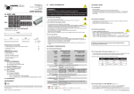
Getting started with the OW-SERVER-ENET-2 is simple. Just follow a few easy steps:
1. Apply power to the OW-SERVER-ENET-2. The green PWR/ACT LED will begin to flash at onesecond intervals, indicating that the product is operating normally. Power must be 5
volts at 400 milliamp (minimum).
2. Connect it to your Network. Connect a
live network cable to the Ethernet Port on
the device. The green LED on the Ethernet
connector will illuminate, indicating a valid
network connection. The yellow LED on
the Ethernet connector blinks only when
there is network traffic.
3. Connect a 1-Wire Device. Connect a supported 1-Wire device to any of the 1-Wire RJ12 connectors.
4. Determine the IP address of the OW-SERVER-ENET-2 by checking your DHCP server logs or
using EDS Appliance Scanner Software available from the EDS website. If the OW-SERVERENET-2 does not find a DHCP server running on your network, it will default to the following IP
address: 169.254.1.1.
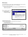
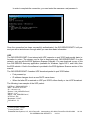
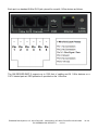
5. Configure your device. Type the IP address of the OW-SERVER-ENET-2 into your web browser (e.g., http://192.168.1.27) and press enter. Select the link on the left called “WEB Setup”.
When the name and password is requested, enter “admin” for the name and “eds” for the password. A
webpage similar to the one shown to the right will enable you to configure and monitor
various aspects of your OW-SERVER-ENET-2.
CONGRATULATIONS! You have successfully installed your Embedded Data Systems’ OWSERVER-ENET-2. Please refer to the Web Access
section of the Operation Manual to obtain an understanding of the function of each of the web pages
served by the OW-SERVER-ENET-2.
Some things to keep in mind:
• The OW-SERVER-ENET-2 has an internal flash
drive that may be used to set it to a fixed IP address.
See the section Configuration/USB for more information.
• See section Additional Resources or EDSPRODUCTS.COM for a list of supported 1-Wire devices.
• No support is provided for OW-SERVER-ENET-2 IP
address identification when utilizing any method other than the EDS Appliance Scanner Software.
Please consult your network administrator if you
cannot locate the DHCP address.
Embedded Data Systems, LLC; 2019 Fortune Dr., Lawrenceburg, KY 40342; Phone/Fax 502-859-5490
EN-USERMAN OW-SERVER 1.1
2.29.12
5 / 38
Interface
The OW-SERVER-ENET-2 has three types of interface:
• Physical—the ports, buttons, and other elements on the unit itself
• Web—the on-board web application that provides real-time access of monitoring data
• Programmatic—the methods by which to interface directly with monitoring data
Physical
The physical interface of the OW-SERVER-ENET-2 includes five parts:
• 1-Wire Connector Panel: provides connectivity to 1-Wire sensors through three (3) RJ12
connectors. Each connector is a separate 1-Wire bus
• Power: a single micro USB connector.
The power connector also has a
USB port, which may be used to
configure the network settings. See
section Configuration/USB
• Ethernet: connects the device to an existing 10/100-baseT network via a standard RJ45
connector
• Power/Activity Indicator: flashes green to indicate the unit is receiving power and operating correctly, flashes yellow to indicate data activity
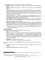
USB
The power / USB port may be used to configure the network settings via the internal flash drive.
This method would typically be used to configure the network settings to a fixed IP address with
the DHCP server turned off, as shown below. See the section Configuration/USB below.
Web
Each OW-SERVER-ENET-2 includes an integrated web-server that provides access to
monitored data from any Internet connected
device such as a web-browser on your PC,
smartphone, or even an iPad®!
The Web interface provides you an easy way
to configure the network setting for the OWSERVER-ENET-2 and is accessible by navigating to its IP address. When you connect
the OW-SERVER-ENET-2 to your network it
will automatically request an IP address from
an available DHCP server if the feature is
turned on, otherwise it will use an IP address
assigned by you. See configuration section below.
Simply open a web browser and enter that IP address to access the web monitoring application.
The web interface provides the following menu items:
Embedded Data Systems, LLC; 2019 Fortune Dr., Lawrenceburg, KY 40342; Phone/Fax 502-859-5490
EN-USERMAN OW-SERVER 1.1
2.29.12
6 / 38
•
•
•
•
•
Overview—the default, opening screen that provides a snapshot of connected devices
and OW-SERVER-ENET-2 basic information
Devices—displays detailed information about each device connected to the OWSERVER-ENET-2
WEB Setup—provides access to security and network configuration information.
1-Wire Setup—provides access to configuration fields for activating direct control of the
1-Wire bus via TCP using ASCII based command set
POST Client Setup—provides access to configuration fields for HTTP Post and Proxy
Server features
Note: If you donʼt know the IP address being assigned to the OW-SERVER-ENET-2 by your
network, simply access your DHCPʼs assignment or download the EDS Appliance Scanner
Software that will automatically find and display the IP address for any OW-SERVER-ENET-2 on
the network. For more information about the EDS Application Scanner software, see section
Additional Resources.
Note: If your network does not have a DHCP server, the OW-SERVER-ENET-2 will default to a
self-assigned address of 169.254.1.1. In the event of this situation, you will need to temporarily
re-configure your computerʼs network settings to be on the same network as the OW-SERVERENET-2 in order to talk to the device for the first time. Only when the OW-SERVER-ENET-2 is in
the same address space as your other computers can you access it using a web browser.
Programmatic
Through a number of different channels, you can access the OW-SERVER-ENET-2 programmatically to create integration with existing systems and network services:
• HTTP—service provides delivery of html and xml data files via http get command, and
firmware upload via http post
• SNMP—provides access to data from all connected sensors, and pushes SNMP traps to
remote listeners for alarming capabilities
• Telnet—service provides ability to monitor the internal activities of the OW-SERVERENET-2 for diagnostic purposes
• UDP Broadcast—listener on port number 30303 will respond to properly formatted packets broadcast to this port number, allowing other devices and applications to discover any
OW-SERVER-ENET-2 that exists on the same network. For assistance in determining
the units IP address, see the section Additional Resources regarding EDS Appliance
Scanner Software
• 1-Wire Interface—service provides a TCP client that implements a command/response
low level interface that may be used to directly control the 1-Wire bus
• POST Client—provides a method of pushing XML data about connected 1-Wire devices
to a server; ideal for circumventing firewall issues
Embedded Data Systems, LLC; 2019 Fortune Dr., Lawrenceburg, KY 40342; Phone/Fax 502-859-5490
EN-USERMAN OW-SERVER 1.1
2.29.12
7 / 38
Configuration
Any configuration of your OW-SERVER-ENET-2 can be carried out through the integrated web
application and, in some cases, the USB port. The on-board, web-based tools provide a method
to configure both the unit itself as well as any attached supported 1-Wire devices. The USB port
provides a way to configure the network settings.
To access the configuration elements,
• Navigate to the IP Address your network has assigned to the OW-SERVER-ENET-2. This
will open the web interface.
From the default “Overview” screen, you can access the configuration options using the lefthand menu:
• Devices
• WEB Setup
• 1-Wire Setup
• POST Client Setup
Embedded Data Systems, LLC; 2019 Fortune Dr., Lawrenceburg, KY 40342; Phone/Fax 502-859-5490
EN-USERMAN OW-SERVER 1.1
2.29.12
8 / 38
WEB Setup
The WEB Setup provides a number of fields to configure the OWSERVER-ENET-2 operations within your network.
Note: In order to access this portion of the web tool, you will need a
username and password. If you
have not set it previously, you can
use the factory default user name
of “admin”, and password of “eds”
(all in lower case.)
You can configure the following
aspects of the OW-SERVERENET-2:
•
Device name—the factory
default is OWServer_v2Enet. However this is a user
definable name, maximum
24 characters. Alphanumeric characters, dashes, periods, spaces and underscores are permitted. This
flexibility allows you to distinguish a device by its location or function for clarity. This field
is included in the XML file.
•
User name—this is the user name, case-sensitive maximum 12 characters, used to access the configuration sections of the on-board web tool and the Telnet interface. Uppercase and lowercase Alphanumeric Characters permitted. The factory default is "admin".
•
Password—this is the password used to access the configuration sections of the onboard web tool and the Telnet interface. Uppercase and lowercase Alphanumeric Characters permitted. The factory default is "eds".
•
Password—confirm the password entered in the previous password field.
•
Host Name—the factory default name for the OW-SERVER-ENET-2 is EDSOWSERVER2. You can change the name but it is limited to 16 UPPERCASE characters. This field
is also printed in the XML file.
•
Enable DHCP—check this box to automatically enable the OW-SERVER-ENET-2 to receive an IP address and other network configuration information (such as gateway and
subnet mask) from a DHCP provider on your network. Note: this is the factory default setting of the device. If you elect NOT to enable DHCP, you must manually provide network
adapter settings for the device:
o IP Address—a standard IPV4 address. Note: if you configure the device with an
IP Address that is NOT a part of your network IP-range or class you will be unable
Embedded Data Systems, LLC; 2019 Fortune Dr., Lawrenceburg, KY 40342; Phone/Fax 502-859-5490
EN-USERMAN OW-SERVER 1.1
2.29.12
9 / 38
to access the device unless connected directly to it with a computer configured
with the same IP settings
o Gateway—the IP address of your network gateway
o Subnet Mask—the Subnet mask
o Primary DNS—the IP address of the primary DNS server
o Secondary DNS—the IP Address of a secondary DNS server. Note: this is optional
o HTTP Port—the port through which the OW-SERVER-ENET-2 will listen for incoming HTTP requests. Normally programmed to 80
•
Save—when you have finished making settings, click the “Save” button to commit the
settings to the device. This will cause the device to reboot
Note: At the time of initial boot-up, the device will look for a DHCP server. If one cannot be
found, the following default configuration settings will be applied:
•
•
•
•
IP Address: 169.254.1.1
Gateway: 169.254.1.1
Subnet Mask: 255.255.0.0
DNS: 169.254.1.1
1-Wire Setup
The 1-Wire Setup feature of
the web-tool allows you to
configure the 1-Wire interface on the OW-SERVERENET-2.
At this time, the only configuration setting allowed is to
enable direct TCP communication with the 1-Wire bus.
This allows you to send
commands directly to 1-Wire
devices connected to the
system. It is ideal for solutions developers looking to integrate the OW-SERVER-ENET-2 with 1Wire devices not currently supported at a high level or for legacy applications. For specific 1Wire commands see Low Level 1-Wire Communication Protocol in Appendix A.
To configure the port
• Click the “Enable” check box `
• Specify a port number through which communication will occur
• When you are finished, click the “Save” Button to commit the settings to the device
Embedded Data Systems, LLC; 2019 Fortune Dr., Lawrenceburg, KY 40342; Phone/Fax 502-859-5490
EN-USERMAN OW-SERVER 1.1
2.29.12
10 / 38
POST Client Setup
The POST Client Setup page of
the web-tool allows you to configure the POST Client and
Proxy features of the OWSERVER-ENET-2.
To configure POST Client
• Enable the feature by
clicking the check box
• Select the URL of the
HTTP POST server. This
field requires a fully qualified URL and may include
an alternate port number.
This example sets the port to 12391:
“http://www.embeddeddatasystems.com:12391/files/myfile.htm”
• Select how often to send the “details.xml” file
• Proxy server may be enabled by clicking the check box
• Set the Proxy URL to the appropriate address, which is typically obtained from the network administrator. For example, if the proxy server is at 192.168.1.230, port number
8080, then the Proxy URL field would be programmed to http://192.168.1.230:8080. These proxy parameters only apply to the POST Client feature, they have no effect on any of
the other features.
USB
The power / USB port may be used to configure the network settings via the internal flash drive.
Using a cable with a micro USB connector, simply plug
the OW-SERVER-ENET-2 into a USB port of a computer
and read the file CONFIG.TXT on the flash drive.
Edit the file as desired, save it, eject the disk and disconnect the OW-SERVER-ENET-2 from the computer's USB
port. Apply power using the wall transformer and the OWSERVER-ENET-2 will power up with the new network settings.
Embedded Data Systems, LLC; 2019 Fortune Dr., Lawrenceburg, KY 40342; Phone/Fax 502-859-5490
EN-USERMAN OW-SERVER 1.1
2.29.12
11 / 38
This method would typically be used to configure the network settings to a fixed IP address with
the DHCP server turned off, as shown below.
Note: The USB port
cannot be used to determine the current IP
address assigned by
the DHCP server.
Embedded Data Systems, LLC; 2019 Fortune Dr., Lawrenceburg, KY 40342; Phone/Fax 502-859-5490
EN-USERMAN OW-SERVER 1.1
2.29.12
12 / 38
Web Access
The OW-SERVER-ENET-2 provides a robust, on-board, web-based tool to access connected 1Wire devices from any web browser—whether on a PC or a smartphone!
To access the connected 1-Wire devices,
• Navigate to the IP Address your network has assigned to the OW-SERVER-ENET-2. This
will open the web interface.
From the default “Overview” page
you can view the following:
• OW-SERVER-ENET-2 Status
• 1-Wire Device information
1-Wire Device Status Overview
The default “Overview” page contains summary data at the top of the page for:
• The OW-SERVER-ENET-2
• Connected devices (in the gray box).
Embedded Data Systems, LLC; 2019 Fortune Dr., Lawrenceburg, KY 40342; Phone/Fax 502-859-5490
EN-USERMAN OW-SERVER 1.1
2.29.12
13 / 38
The OW-SERVER-ENET-2 summary data provides the following points:
• Firmware version—the version of firmware currently operating on the OW-SERVERENET-2
• Devices connected—the number of 1-Wire devices connected to the OW-SERVERENET-2
• Device poll count—the number of times the OW-SERVER-ENET-2 has polled devices.
The rate of polling depends upon the number of devices and the specific device. Some 1Wire devices refresh every second while others may do so much faster (e.g., The
DS18B20 causes a 900ms delay while waiting for the temperature to be converted,
whereas the DS2406 has no delay).
• Connection status—the connection status between the OW-SERVER-ENET-2 and the
web browser that is accessing the OW-SERVER-ENET-2 web configuration page. An error will be displayed here in the event there is an issue.
• Data activity—this light will flash green every time the browser receives a data push of
new values from the OW-SERVER-ENET-2. This is useful to know that the data feed is
alive, even if the values are not changing.
• Enable auto update—check this box to enable the browser to update the webpage as
new data is received from the OW-SERVER-ENET-2. Uncheck the box if you would like
to pause the automatic refresh between browser and the OW-SERVER-ENET-2 to analyze information on the screen. Note: if you leave this box unchecked, the web page will
not update with new values automatically but the OW-SERVER-ENET-2 will continue to
poll attached 1-Wire devices.
Connected Devices
The Connected Devices summary data provides the following points:
• Name—the name of the device
• Health—the health of the device. Each time a device is successfully read, its health field
is incremented by 1, to a maximum value of 7. If a device fails to read properly for any
reason, its health field is decremented by 1, to a minimum value of 0. Generally, a health
value of 7 indicates a properly functioning device, 0 indicates a device that has been disconnected, and anything in between might indicate intermittent communication or a recently connected device.
• Description—the description of the device1
• Value—the primary value of the sensor on the connected device
During normal operation the OW-SERVER-ENET-2 automatically scans the 1-Wire bus as follows:
•
•
Searches for devices—if new devices are found, they are added to the end of the device list2
Reads data from all devices—updates the data fields
1
Please note that the description is commonly based on the Maxim chips, not the sensor connected to the
chip.
2
The order of devices in the list may change if the power is cycled.
Embedded Data Systems, LLC; 2019 Fortune Dr., Lawrenceburg, KY 40342; Phone/Fax 502-859-5490
EN-USERMAN OW-SERVER 1.1
2.29.12
14 / 38
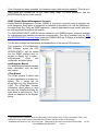
1-Wire Device Details
To access details about the connected devices:
• Choose the “Devices” menu on the left. This will open the Connected Devices screen.
The Connected Devices
screen displays all 1-Wire
devices that are currently
connected to the OWSERVER-ENET-2. The data is presented in two
sets—1-Wire interface and
the connected devices.
Communications
The top of the screen shows information about the communication status between the OWSERVER-ENET-2, the 1-Wire devices as a group, and the web browser:
•
•
Devices Connected—the total # of
devices connected
Connection
status—the connection
status between the
OW-SERVERENET-2 and the
web browser that is accessing the OW-SERVER-ENET-2 web configuration page. An error will be displayed here in the event there is an issue.
Embedded Data Systems, LLC; 2019 Fortune Dr., Lawrenceburg, KY 40342; Phone/Fax 502-859-5490
EN-USERMAN OW-SERVER 1.1
2.29.12
15 / 38
•
•
•
•
•
•
Device poll count—the number of times the OW-SERVER-ENET-2 has cycled through
polling all of the connected devices
Loop time—the time, in seconds, it takes for the OW-SERVER-ENET-2 to cycle through
polling all of the devices and receive a response. As more devices are added, each individual device gets read less frequently since only a single device can be read at a time.
This value is useful for determining how frequently each sensor gets read.
Power Voltage – the voltage of the power supply
Data activity—this light will flash green every time the browser receives a data push of
new values from the OW-SERVER-ENET-2. This is useful to know that the data feed is
alive, even if the values are not changing.
Enable auto update—check this box to enable the browser to update the webpage as
new data is received from the OW-SERVER-ENET-2. Uncheck the box if you would like
to pause the automatic refresh between browser and the OW-SERVER-ENET-2 to analyze information on the screen. Note: if you leave this box unchecked, the web page will
not update with new values automatically but the OW-SERVER-ENET-2 will continue to
poll attached 1-Wire devices.
Channel chart – displays parameters specific to each channel
o Devices – number of devices on each channel
o Voltage – voltage of each channel
o Errors—number of errors on the 1-Wire bus for each channel
Embedded Data Systems, LLC; 2019 Fortune Dr., Lawrenceburg, KY 40342; Phone/Fax 502-859-5490
EN-USERMAN OW-SERVER 1.1
2.29.12
16 / 38
Connected Devices
The bottom part of the screen displays information about each connected device. Because each
supported device may have different elements, they are not covered in detail in this manual.
For those devices that have “programmable” elements (e.g., UserByte1 and UserByte2 in the
Programmable Resolution Thermometer example depicted above), you can click the “Write” button to specify a value.
All of the current sensor data is available for download at the details.xml link on the bottom of
the page.
Embedded Data Systems, LLC; 2019 Fortune Dr., Lawrenceburg, KY 40342; Phone/Fax 502-859-5490
EN-USERMAN OW-SERVER 1.1
2.29.12
17 / 38
Integration
The OW-SERVER-ENET-2 provides a powerful set of tools to enable developers and network
administrators the ability to integrate the device (and data from connected 1-Wire devices) with
existing management and/or monitoring systems. The following are the network services supported by OW-SERVER-ENET-2, accessible via TCP/IP:
• HTTP—service provides delivery of html and xml data files via http get, a method of writing data to 1-Wire devices, the web browser interface previously discussed and firmware
upgrading
• SNMP—provides access to data from all connected sensors, and pushes SNMP traps to
remote listeners for alarming capabilities
• Telnet—service provides login to monitor some of the OW-SERVER-ENET-2’s communication activities for diagnostic purposes
• UDP Broadcast—listener on port number 30303 will respond to properly formatted packets broadcast to this port number, allowing other devices and applications to discover
OW-SERVER-ENET-2s that exist on the same network.
• 1-Wire Interface—service provides a TCP client that implements a command / response low level interface that may be used to directly control the 1-Wire bus
• POST Client—provides a method of pushing XML data about connected 1-Wire devices
to a server.
HTTP
The HTTP mechanism enables programmers to utilize a GET command to retrieve various data
elements that are contained in an XML file as well as write data to 1-Wire devices that support
control functions.
The OW-SERVER-ENET-2 provides the following XML file for data retrieval:
• Details.xml—this file provides detailed information on the OW-SERVER-ENET-2 and all
connected devices.
Retrieving XML File
To retrieve the XML file, simply access it by corresponding URL.
For example: “http://192.254.1.1/details.xml”
Once the file has been retrieved, it can be parsed according to the methods available to the developer in whatever programming language they are using.
Details.xml
The following is an example of the details.xml file:
<Devices-Detail-Response xmlns="http://www.embeddeddatasystems.com/schema/owserver"
xmlns:xsi="http://www.w3.org/2001/XMLSchema-instance">
<PollCount>85</PollCount>
<DevicesConnected>1</DevicesConnected>
<LoopTime>1.046</LoopTime>
<DevicesConnectedChannel1>0</DevicesConnectedChannel1>
Embedded Data Systems, LLC; 2019 Fortune Dr., Lawrenceburg, KY 40342; Phone/Fax 502-859-5490
EN-USERMAN OW-SERVER 1.1
2.29.12
18 / 38
<DevicesConnectedChannel2>0</DevicesConnectedChannel2>
<DevicesConnectedChannel3>1</DevicesConnectedChannel3>
<DataErrorsChannel1>0</DataErrorsChannel1>
<DataErrorsChannel2>0</DataErrorsChannel2>
<DataErrorsChannel3>0</DataErrorsChannel3>
<VoltageChannel1>4.83</VoltageChannel1>
<VoltageChannel2>4.85</VoltageChannel2>
<VoltageChannel3>4.76</VoltageChannel3>
VoltagePower>5.08</VoltagePower>
<DeviceName>OWServer_v2-Enet</DeviceName>
<HostName>EDSOWSERVER2</HostName>
<MACAddress>00:04:A3:19:E9:ED</MACAddress>
<owd_DS18B20 Description="Programmable resolution thermometer">
<Name>DS18B20</Name>
<Family>28</Family>
<ROMId>7B0000030EBA4E28</ROMId>
<Health>7</Health>
<Channel>3</Channel>
<RawData>6E0107087FFF021032FF00000000000000000000000000000000000000000000
0000000000000000000000000000000000000000000000000000000000000000000000000
0000000000000000000000000000000000000000000000000000000000000000000000000
0000000000000000000000000000000000000000000000000000000000000000000000000
0000000000000000000000000000000000000</RawData>
<PrimaryValue>22.8750 Deg C</PrimaryValue>
<Temperature Units="Centigrade">22.8750</Temperature>
<UserByte1 Writable="True">7</UserByte1>
<UserByte2 Writable="True">8</UserByte2>
<Resolution>12</Resolution>
<PowerSource>255</PowerSource>
</owd_DS18B20>
</Devices-Detail-Response>
Each “owd_xxx” element contains the device name (Name), family code (Family), ROM ID
(ROMId), health (Health), raw data used to obtain the data fields (RawData) displayed in hex
format, and a list of the data fields where the name of the data field provides the description.
Writing Data to 1-Wire Devices
To write data to a connected 1-Wire device that supports control commands simply make a request of devices.htm with the appropriate URL parameters. Below is an example:
devices.htm?rom=4300000200AD1928&variable=UserByte1&value=75
The URL parameters in the example are as follows:
• rom—the ROM ID of the device to modify, alpha characters must be upper case
•
variable—the name of the variable to modify. The name is the same as the XML field
name, only XML fields with attributes of ‘Writable=”True”’ may be written, (e.g., <UserByte....)
•
value—the new decimal value to write to the 1-Wire device
Firmware Upgrading
Firmware may be upgraded using the link on the “WEB Setup” page. At the bottom, under the
heading “Board Maintenance” is a link to upload new firmware. Follow the instructions to complete the process.
Embedded Data Systems, LLC; 2019 Fortune Dr., Lawrenceburg, KY 40342; Phone/Fax 502-859-5490
EN-USERMAN OW-SERVER 1.1
2.29.12
19 / 38
Once firmware has been upgraded, the firmware support data must be updated. This link is directly below the firmware link on the “WEB Setup” page. For more information, see the
MAINTENANCE section of this manual.
SNMP (Simple Network Management Protocol)
Simple Network Management Protocol (SNMP) is a protocol commonly used to maintain network equipment. Every piece of equipment in a network is described in its .mib file (Machine Information Base file); Using an SNMP application, network administrators can monitor and interact with equipment throughout the network.
The OW-SERVER-ENET-2-MIB file can be loaded into your SNMP program, making it available
for management and machine-to-machine communication. This file is available from the EDS
OW-SERVER-ENET-2 product page under the DOWNLOADS tab. It defines all available SNMP
nodes available, complete with a text description.
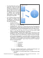
The file also contains text descriptions and explanations of the various OID functions.
This screenshot of the iReasoning
MIB Browser1 shows the OWSERVER-ENET-2 .mib file loaded
into the SNMP interface and expanded to display the 3 nodes—
edsEnterprise,
dTrap
and
owDevices, as shown below.
edsEnterprise Branch
The edsEnterprise branch presents
basic information such as name
and version.
dTrap Branch
The dTrap contains 2 tables used
to send traps based on preset conditions. The 2 tables are the
dTrapTable and the dTrapDeviceTable. The dTrapTable contains
information about where to send
the trap, the dTrapDeviceTable defines when to send the trap. The 2
tables are depicted in the diagram
below.
1
This application is available from the iReasoning website and is only used as an example. There is no
affiliation of any kind between Embedded Data Systems and the creator of iReasoning.
Embedded Data Systems, LLC; 2019 Fortune Dr., Lawrenceburg, KY 40342; Phone/Fax 502-859-5490
EN-USERMAN OW-SERVER 1.1
2.29.12
20 / 38
•
The dTrapTable defines where to
send traps. It has 2 rows, each
defining an IP address, community string and enable flag. In order for a trap to be sent, the IP
address must not be zero and
the enable flag must be one (zero disables). The community
string is not used by the OWSensor-ENET-2, except to send
the string in the trap PDU.
•
The dTrapDeviceTable specifies
the criteria for sending a trap.
The table has 7 rows that support 7 different traps. The rows of
this table are as follows:
o dTrapDeviceEnable
–
must be 1 to enable
sending traps, zero disables sending
o dTrapSendPointer – may be 0 or 1. Points to the row of the dTrap table which
defines where to send the trap. Note that all data in the row in this table and
the corresponding row of the dTrap table must be valid for the trap to be sent.
o dTrapDeviceROM – Stores the 1-Wire ROM ID of the device to base sending
traps on. To be valid, this value must not be zero and must match a ROM
code of a currently connected and active 1-Wire device.
o dTrapDeviceVariable – Defines which variable of the 1-Wire device to base
calculation on. The value must refer to a valid variable or no trap will be sent.
The variable number can be determined by viewing the Devices web page,
each line below “PrimaryValue” is a potential variable, numbered sequentially.
For example, the DS18B20 has as the first item below “PrimaryValue” the item
“Temperature”, so this is number 0. The next item is “UserByte1”, so this is
item 1, after that is “UserByte2”, which is item 2, then item 3 is “Resolution”
and item 4 is “PowerSource”.
DS18B20
•
•
•
•
•
0 – Temperature
1 – User byte 1
2 – User byte 2
3 – Resolution
4 – Power source
o The items dTrapDeviceHighThreshold, dTrapDeviceLowThreshold and
dTrapDeviceHysteresis work together to define 3 windows.
The variable is in the high window when it is greater than the high
threshold
Embedded Data Systems, LLC; 2019 Fortune Dr., Lawrenceburg, KY 40342; Phone/Fax 502-859-5490
EN-USERMAN OW-SERVER 1.1
2.29.12
21 / 38
The variable is in the middle window when it becomes less than or
equal to the high threshold minus hysteresis, or greater than or equal
to the low threshold plus hysteresis
It is in the low window when it is less than the low threshold
When a variable is read from a 1-Wire device, it is compared to these
values. If the new value from the 1-Wire device causes a change in
the windows, this generates a trap message with this information:
•
OID of dTrapDeviceIndex.x where x is the number of
dTrapDeviceTable row that caused the trap. The numeric value is 1.3.6.1.4.1.3.1440.2.2.1.1.x.
•
The data type integer indicates which transition occurred:
o 1 – middle to high window transition
o 2 – high to middle window transition
o 3 – middle to low transition
o 4 – low to middle transition
•
•
If the high threshold is less than the low threshold, no traps
will be generated. Hysteresis is not checked for validity and
may be set to any value.
•
The high threshold, low threshold and hysteresis are stored as
float in the OW-SERVER-ENET-2, but are written as strings.
This is because the SNMP V1 protocol makes no provision for
a float. Because of this, some numbers may be rounded, and
are displayed with 3 digits of precision after the decimal point
regardless of what the number actually is in the OWSERVER-ENET-2.
The owDevices has the following branches:
o
owDeviceTypes lists each device type supported. This branch is
read only.
o
owDeviceInfo branch lists the number of devices connected
o
owDeviceTable shows basic information about each device connected
o
These are the specific device tables, for example owDS18B20Table
defines the DS18B20. See the latest version of the EDS MIB file for
a list and description of the devices supported and their associated
parameters.
Embedded Data Systems, LLC; 2019 Fortune Dr., Lawrenceburg, KY 40342; Phone/Fax 502-859-5490
EN-USERMAN OW-SERVER 1.1
2.29.12
22 / 38
Telnet
Telnet is a network protocol used on the Internet or local area networks to provide a bidirectional
interactive text-oriented communications facility using a virtual terminal connection. User data is
interspersed in-band with Telnet control information in an 8-bit byte oriented data connection
over the Transmission Control Protocol (TCP).
In most operating systems, Telnet connections are enabled through the Telnet Client program,
which is run in a terminal window (as illustrated above). To start a Telnet connection with the
OW-SERVER-ENET-2,
• Open the Telnet program. This is accomplished by typing “Telnet” into the search box (of
a windows computer) or “Telnet” in a terminal window of a Mac or Linux computer.
• Once the Telnet program has opened, type “open {IP address}” where {IP address} represents the IP address of your OW-SERVER-ENET-2 (e.g., open 192.168.1.14). This will
open a connection between your Telnet program and the OW-SERVER-ENET-2.
Embedded Data Systems, LLC; 2019 Fortune Dr., Lawrenceburg, KY 40342; Phone/Fax 502-859-5490
EN-USERMAN OW-SERVER 1.1
2.29.12
23 / 38
In order to complete the connection, you must enter the username1 and password.2
Once the connection has been successfully authenticated, the OW-SERVER-ENET-2 will present you with a textual menu through which you can show basic information.
UDP
The OW-SERVER-ENET-2 can interact with UDP requests on port 30303 and provide basic information in return. The primary use for this is discovering any OW-SERVER-ENET-2 on the
network, such as with the EDS Appliance Scanner Software. You can download a copy of this
free OW-SERVER discovery application (available for Windows, Apple OS X, and Linux) from
the EDS website. A link to the software is provided in the EDS Appliance Scanner section of this
manual.
The OW-SERVER-ENET-2 sends a UDP broadcast packet to port 30303 when:
• First powered up
• IP address changes due to a new DHCP server lease
• When the letter ‘D’ is received on UDP port 30303, either directly or via a UDP broadcast.
The following is an example of the UDP packet:
{"NETBios": "EDSOWSERVER ",
"MAC": "00-50-C2-91-B1-44",
"IP": "192.168.1.14",
"Product": "OW_SERVER-Enet-2",
"FWVer": "1.01",
"Name": "OW_SERVER-Enet-2",
"HTTPPort": "80",
"Bootloader": "POST",
"TCPIntfPort": "0",
}
1
2
Factory default "admin"
Factory default "eds"
Embedded Data Systems, LLC; 2019 Fortune Dr., Lawrenceburg, KY 40342; Phone/Fax 502-859-5490
EN-USERMAN OW-SERVER 1.1
2.29.12
24 / 38
The packet is formatted using JSON (Javascript Object Notation). The fields have the following
information
• NETBios—This is the text string programmed in the “Host Name” field of the “Web Setup” web page
• MAC—This is the globally unique MAC address of the OW-SERVER-ENET-2
• IP—The current IP address
• Product—A text description of the product. It cannot be changed
• FWVer—Firmware version of the OW-SERVER-ENET-2
• Name—This is the text string programmed in the “Device Name” field of the “Web Setup”
web page
• HTTPPort—The HTTP port number as programmed in the “HTTP Port” field of the “Web
Setup” web page. The standard HTTP port is 80.
• Bootloader—Specifies the boot-loader type
• TCPIntfPort—This is the 1-Wire interface port as programmed in the “Port” field of the “1Wire Setup” web page
Embedded Data Systems, LLC; 2019 Fortune Dr., Lawrenceburg, KY 40342; Phone/Fax 502-859-5490
EN-USERMAN OW-SERVER 1.1
2.29.12
25 / 38
Low Level 1-Wire Interface
The 1-Wire Interface provides a command level interface to directly control the 1-Wire bus
through a TCP connection. This feature is provided for integration to products that have already
implemented a low level interface for other 1-Wire bus masters and is for experienced 1-Wire
integrators only.
When a TCP connection is made, the OW-SERVER-ENET-2 stops polling 1-Wire devices and
waits for commands over the TCP connection. If 30 seconds elapse without any commands, the
OW-SERVER-ENET-2 closes the TCP connection and resumes normal polling of 1-Wire devices. Optionally, the user may send a quit command to avoid the 30 seconds delay.
See Appendix A for LOW LEVEL 1-WIRE COMMUNICATION PROTOCOL
POST Client
This feature automatically, on a timed basis, sends the XML file “details.xml” to a HTTP server.
Its primary purpose is to get data thatʼs behind a firewall to a server residing on the Internet. By
using the standard HTTP POST originating from behind the firewall, firewalls and other Internet
filters see the communication as a standard browser request and typically will not block it.
An HTTP proxy server has been included for the POST Client.
The HTTP POST feature requires a properly configured server to receive the file. Download the
OW-SERVER-ENET-2 PHP Script from the EDS website to perform this function.
Embedded Data Systems, LLC; 2019 Fortune Dr., Lawrenceburg, KY 40342; Phone/Fax 502-859-5490
EN-USERMAN OW-SERVER 1.1
2.29.12
26 / 38
Maintenance
The activities you can carry out to maintain and/or upgrade your OW-SERVER-ENET-2 include:
• Firmware and support files upgrade
• Factory reset
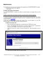
Firmware and Support Files Upgrade
The OW-SERVER-ENET-2 features the ability to upload firmware and support files over the
network.
Update of support files must always be done in conjunction with a firmware upgrade.
To locate your current installed firmware version, access the Overview Web Page. The version
of firmware installed in your device is listed at the top. To determine if there is a more recent
version available, contact EDS.
If EDS has provided you new firmware and support files, you can upload it to your OWSERVER-ENET-2 via the WEB using the following procedure:
1) Update the firmware files:
•
Open the web-based configuration tool and select the “WEB Setup” screen.
•
Scroll to the paragraph near the bottom of the page, beginning with "To upload new
firmware, CLICK HERE". Click the link to begin the procedure
•
Click the “Choose File” button to locate and select the *.hex file provided to you by
EDS
•
Once the file is located, click the “Upload” button
Embedded Data Systems, LLC; 2019 Fortune Dr., Lawrenceburg, KY 40342; Phone/Fax 502-859-5490
EN-USERMAN OW-SERVER 1.1
2.29.12
27 / 38
•
It can take over 30 seconds to upload the firmware, if successful the following page
will display prompting you to reset the device and complete the process by selecting
"CLICKING HERE"
•
•
•
Approximately 10 seconds after reset, the green LED will flash at a 1 second rate, indicating completion.
•
Verify the upload was successful by viewing the new version of firmware on the Overview page.
2) Update the Support files:
•
Open the web-based configuration tool and select the “WEB Setup” screen
•
Scroll to the paragraph near the
bottom of the page, beginning
with "To upload new firmware
support data, CLICK HERE".
Click the link to begin the procedure
•
Click the “Choose File” button to
locate and select the *.bin file provided to you by EDS
•
Once the file is located, click the
“Upload” button
•
Once complete, the OW-SERVER-ENET-2 will apply the new file and return the message "MPFS Update Successful"
•
Select "Site main page" to return to "OVERVIEW" screen
•
NOTE: Be certain to clear the cache in your web browser; otherwise the new web
pages will not be displayed.
Embedded Data Systems, LLC; 2019 Fortune Dr., Lawrenceburg, KY 40342; Phone/Fax 502-859-5490
EN-USERMAN OW-SERVER 1.1
2.29.12
28 / 38
Factory Reset
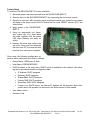
To reset the OW-SERVER-ENET-2 to factory defaults:
1. Be certain power has been removed from the OW-SERVER-ENET-2
2. Remove the lid of the OW-SERVER-ENET-2 by unscrewing the four corner screws
3. Once lid is removed, with connector panel positioned towards you, locate the two plated
drill holes in the upper center of the PC board with the word “RESET” above it (P2). See
photo below.
4. Apply power to the OW-SERVERENET-2
5. Using an appropriate tool (tweezers, paper clip, etc.) short these
two pads together until the green
LED stops flashing and stays on
solidly.
6. Remove the short and replace the
top cover. Once you have removed
the short from P2, the reset will take
less than four seconds to complete.
Once reset, the following configuration elements will be returned to their factory settings:
•
Device Name: OWServer_v2-Enet
•
Host Name: EDSOWSERVER2
•
DHCP Enabled. In the event that a DHCP server is available on the network, the following will be provided automatic configuration data:
•
IP Address: DHCP assigned
Gateway: DHCP assigned
Subnet Mask: DHCP assigned
Primary DNS: DHCP assigned
Secondary DNS: DHCP assigned
If there is no DHCP server, an internal IP address will be provided. More information about this process can be found in the Setup section of this manual.
User Name: admin
•
Password: eds
Embedded Data Systems, LLC; 2019 Fortune Dr., Lawrenceburg, KY 40342; Phone/Fax 502-859-5490
EN-USERMAN OW-SERVER 1.1
2.29.12
29 / 38
Additional Resources
Below is a list of additional resources:
• Supported 1-Wire devices
• EDS Appliance Scanner Software
• OW-SERVER-ENET-2 form factor
Supported 1-Wire Devices
The OW-SERVER-ENET-2 supports the following 1-Wire devices:
•
•
•
•
•
•
•
DS18B20 - Programmable Resolution Thermometer
DS18S20 - Parasite Power Thermometer
DS2406 - Dual Addressable Switch Plus Memory
DS2408 - 8 Channel Addressable Switch
DS2423 - RAM with Counters
DS2438 - Smart Battery Monitor
DS2450 - Quad A/D Converter
•
•
•
•
•
•
DS18B20 - OW-TEMP-B3-12xA — Temperature Probe
DS18B20 - OW-TEMP-BF-12x — Foil Tape Temperature Sensor
DS18B20 - OW-TEMP-BW-12X — Wall Mount Temperature Sensor
DS18S20 - OW-TEMP-S3-12x — Temperature Probe
DS18S20 - OW-TEMP-SF-12x — Foil Tape Temperature Sensor
DS18S20 - OW-TEMP-SW-12x — Wall Mount Temperature Sensor
•
•
•
•
•
•
DS18B20 - OW-ENV-T — Temperature sensor
EDS0064 - OW-ENV-TR — Temperature sensor w/relay
EDS0065 - OW-ENV-TH(R) — Temperature and humidity sensor (w/relay)
EDS0066 - OW-ENV-TP(R) — Temperature and barometric pressure sensor (w/relay)
EDS0067 - OW-ENV-TL(R) — Temperature and light sensor (w/relay)
EDS0068 - OW-ENV-THPL(R) — Temperature, humidity, barometric pressure and light
sensor (w/relay)
EDS0070 - OW-VIB(-R)— Vibration sensor (w/relay)
EDS0071 - OW-RTD4W(-R) — RTD reader, 4 wire (w/relay)
EDS0080 - OW-IO-AI8-420(-R) — Octal 4-20 milliamp input (w/relay)
EDS0082 - OW-IO-AI8-10V(-R) — Octal 0-10 volt input (w/relay)
EDS0083 - OW-IO-AI4-420(-R) — Quad 4-20 milliamp input (w/relay)
EDS0085 - OW-IO-AI4-10V(-R) — Quad 0-10 volt input (w/relay)
EDS0090 - OW-IO-DIO8(-R) — Octal discrete input/output (w/relay)
•
•
•
•
•
•
•
Embedded Data Systems, LLC; 2019 Fortune Dr., Lawrenceburg, KY 40342; Phone/Fax 502-859-5490
EN-USERMAN OW-SERVER 1.1
2.29.12
30 / 38
EDS Appliance Scanner Software
In some instances, it may not be easy to obtain the IP address of an OW-SERVER-ENET-2 via
DHCP router tables. Therefore, EDS offers a Windows application that will utilize the UDP
communication method available on any OW-SERVER-ENET-2 to retrieve the IP address of
any OW-SERVER-ENET-2 connected to the network.
This application software can be downloaded at EDS Appliance Scanner Software. If you have
difficulty downloading the software from this link, contact EDS.
OW-SERVER-ENET-2 Form Factor
The OW-SERVER-ENET-2 is available in panel mount form factor, suitable for mounting on
desktop or wall.
Power Supply Requirements
The OW-SERVER-ENET-2 is fitted with a USB micro-B receptacle suitable for connection to
any 5 Volt DC power supply having a USB micro-B plug. The OW-SERVER-ENET-2 has a typical current draw of 245ma with no devices connected; however a power supply with at least
400ma capacity is required for correct operation. The input is reversed voltage protected, although use of a standard micro USB wall transformer such as used to charge cellular phones
should avoid any reverse or over voltage issues. The voltage must be 5 Volts +/- 10%. The OWSERVER-ENET-2 was tested to meet FCC, CSA, CE, and C-check using the Emerson DCH3050EU-0006 wall power supply.
Ethernet Interface
The OW-SERVER-ENET-2 is equipped with a standard RJ45 Ethernet jack for 10/100 BASE-T.
The half duplex mode of operation is supported on the Ethernet interface. If you are connecting
to a hub or switch, a straight through cable should be used. If connecting directly to a PC, then a
crossover cable should be used. The Ethernet connector has 2 LEDs; the green indicates connection to the network and the yellow indicates network traffic.
Note: The traffic indicator LED indicates any traffic on the network, not just traffic addressed to
the OW Server. This is a hardware function.
Embedded Data Systems, LLC; 2019 Fortune Dr., Lawrenceburg, KY 40342; Phone/Fax 502-859-5490
EN-USERMAN OW-SERVER 1.1
2.29.12
31 / 38
1-Wire Interface
For ease of use, the OW-SERVER-ENET-2 is equipped with three 1-Wire ports that are driven
separately. By driving each port separately, electromagnetic interference is reduced, electrical
reflections are reduced, each connector has more power available for parasite powered devices
and devices can be physically located based on the bus they are connected to.
Each of the 1-Wire ports has an associated 10 ohm resistor and jumper. The resistor is in series
with the +5V out line and the jumper is in parallel with the resistor. Applying a solder bridge to
the jumper shorts the resistor allowing a greater amount of current to flow to the device via the
+5v out pin. Only under extreme conditions should it be necessary to short this jumper.
Embedded Data Systems, LLC; 2019 Fortune Dr., Lawrenceburg, KY 40342; Phone/Fax 502-859-5490
EN-USERMAN OW-SERVER 1.1
2.29.12
32 / 38
Each port is a standard 6-Wire RJ12 jack, pinned for use with 1-Wire devices as follows:
The OW-SERVER-ENET-2 supports up to 1000 feet of cabling and 24 1-Wire devices on a
CAT-5 twisted pair net. ESD protection is provided on the 1-Wire bus.
Embedded Data Systems, LLC; 2019 Fortune Dr., Lawrenceburg, KY 40342; Phone/Fax 502-859-5490
EN-USERMAN OW-SERVER 1.1
2.29.12
33 / 38
Power Supply Schematic
!-!-"4
&-
&
$
",
!3
%
/&
$$&
1
!33
.&
,$
$
2
/
.
3
%
!3%
.&
!
/&
'
0
1!
1
!#
!#
!#
!#
!#
!#
/&
2
#,,-!
,/
!"#$%&"!'#&&()*#)+
1-Wire Interface Schematic
Specifications
PARAMETER
MIN
TYP
MAX
UNITS
Operating Temperature
-40
-
85
°C
Storing Temperature
-40
-
85
°C
Operating Humidity (non-condensing)
0
-
90
%
Storing Humidity (non-condensing)
0
-
90
%
Supply Voltage DC +/-10%
-
5
-
Volts
Rated Current (average) with Ethernet but no 1-Wire
devices connected
-
245
-
mA
Communication
10/100Base-T Ethernet
Enclosure Dimensions (L x W x H)
139.7
85.27
31.75
mm
Weight
-
.2
-
kg
Embedded Data Systems, LLC; 2019 Fortune Dr., Lawrenceburg, KY 40342; Phone/Fax 502-859-5490
EN-USERMAN OW-SERVER 1.1
2.29.12
34 / 38
Support
Embedded Data Systems provides a comprehensive FAQ and online support system accessible
from their website. This support system includes the most up-to-date information about the OWSERVER-ENET-2 product family.
Compliance
FEDERAL COMMUNICATIONS COMMISSION (FCC) COMPLIANCE STATEMENT
This device complies with part 15 of the FCC Rules. Operation is subject to the following two
conditions: (1) This device may not cause harmful interference, and (2) this device must accept
any interference received, including interference that may cause undesired operation.
INDUSTRY CANADA (IC) COMPLIANCE STATEMENT
This Class B digital apparatus complies with Canadian ICES-003.
Cet appareil numérique de la classe B est conforme à la norme NMB-003 du Canada.
EUROPEAN COMMUNITY (EC) DIRECTIVES CONFORMITY
APPLICATION OF COUNCIL DIRECTIVE 2004/108/EC Standard to which Conformity is
Declared:
EN 61326-1:2006
(Emmissions)
EN 61326-2-3:2006
(Immunity)
EN 61000-3-2:2006+A1:2009+A2:2009 (Harmonics)
EN 61000-3-3:2008
(Flicker)
Caution: The manufacturer is not responsible for any radio or television interference
caused by using other than recommended cables or by unauthorized changes or
modifications to this equipment. Unauthorized changes or modifications could void the
user’s authority to operate this equipment.
Acknowledgements
1-Wire is a registered trademark of Maxim Integrated Products, Inc.
Windows is a registered trademark of Microsoft Corporation in the United States and other countries.
Embedded Data Systems, LLC; 2019 Fortune Dr., Lawrenceburg, KY 40342; Phone/Fax 502-859-5490
EN-USERMAN OW-SERVER 1.1
2.29.12
35 / 38
Appendix A
Low Level 1-Wire Communication Protocol
COMMANDS
'R'
1-Wire Reset - Generates a reset pulse on the 1-Wire bus, returns 'N' or 'P' for presence
pulse
'S'
First search ROM
's'
Next search ROM
'C'
First conditional search ROM
'c'
Next conditional search ROM
'A'
Address select with send - Address follows command; address is copied to 'active ROM'
and is sent out 1-Wire bus using 'M' command
'a'
Address select without send - Address follows command, address is copied to 'active
ROM' but is not sent out 1-Wire bus
'M'
Match ROM - Address stored in 'active ROM' is sent out 1-Wire bus
'm'
Match ROM, set overdrive speed - Required as the next command after setting overdrive
speed, to be used only once
'W'
Write a block of data, up to 64 bytes. Data follows command (no byte count)
'Q'
Overdrive speed select
'q'
Standard speed select
'Z'
Write a zero bit
'O'
Write a one bit
‘I’
Get information about the device
'h'
Disable interface
RESPONSES
'!'
Error
'+'
OK
'?'
Ready for commands, sent at initial connect
'XXX" Data
Embedded Data Systems, LLC; 2019 Fortune Dr., Lawrenceburg, KY 40342; Phone/Fax 502-859-5490
EN-USERMAN OW-SERVER 1.1
2.29.12
36 / 38
COMMUNICATION
The OW server communicates with a client using a TCP socket. The OW server maintains the
server side, listening on the programmed port. Only 1 socket is supported. If desired, the feature
can be disabled via programming.
When first connecting, the OW server will send a "?" when commands may be sent.
PACKET FORMAT
The OW server accepts incoming connection requests and listens for data. Data is sent to the
client in response to packets received from the client. Packets sent to the OW server have this
format:
Command - single char
Channel - single char, must be 1, 2 or 3 (not required for the I or h command)
Data - sent as ASCII encoded hex, up to 128 bytes or 256 characters
Carriage return - termination char
Data sent from the OW server to the client has this format:
Data - sent as ASCII encoded hex, up to 128 bytes or 256 characters
Carriage return - termination char (a line feed is also sent)
AUTO UPDATE LOCKOUT
The OW server automatically reads 1-Wire devices continuously. This feature is turned off when
the low level interface becomes active, such as when:
1. A client connects to the TCP socket.
Any valid command restarts a 30 second timer. Auto updating is turned on, and the socket is
closed when:
• The 'disable interface' command is received, or
• No commands are received for 30 seconds, or
• The client disconnects
Embedded Data Systems, LLC; 2019 Fortune Dr., Lawrenceburg, KY 40342; Phone/Fax 502-859-5490
EN-USERMAN OW-SERVER 1.1
2.29.12
37 / 38
EXAMPLE
The following example illustrates how to initiate a temperature conversion for each channel,
then read the result of a DS18B20 on channel 1.
Temperature conversion for each channel. (Channel can be skipped if no
device exists on the channel)
Reset 1-Wire Bus Channel 1
tx:
R1
Presence Pulse received
rx:
P
Write to Channel 1 the "Skip ROM" command
tx:
W1CC
Data received
rx:
CC
tx:
W144
rx:
tx:
rx:
tx:
rx:
44
R2
P
W2CC
CC
tx:
W244
rx:
tx:
rx:
rx:
rx:
44
R3
P
W3CC
CC
Write to Channel 1 the "Convert T" command.
After this command is executed no activity is
permitted on the 1-Wire bus for at least
750ms to allow parasite powered devices to
complete their conversion
Data received
Reset 1-Wire Bus Channel 2
Presence Pulse received
Write to Channel 2 the "Skip ROM" command
Data received
Write to Channel 2 the "Convert T" command.
After this command is executed no activity is
permitted on the 1-Wire bus for at least
750ms to allow parasite powered devices to
complete their conversion
Data received
Reset 1-Wire Bus Channel 3
Presence Pulse received
Write to Channel 3 the "Skip ROM" command
Data received
tx:
W344
Write to Channel 3 the "Convert T" command.
After this command is executed no activity is
permitted on the 1-Wire bus for at least
750ms to allow parasite powered devices to
complete their conversion
rx:
44
Data received
Individually address DS18B20 on Channel 1
tx:
R1
Presence Pulse received
rx:
P
Address the DS18B20 on channel 1
tx:
A1CD00000027C5CD28
Command accepted
rx:
+
Display scratchpad data of DS18B20
tx:
W1BEFFFFFFFFFFFFFFFFFF
rx:
BE90014B467FFF101092
Data Received.
(Interpreting scratchpad data is covered
in the DS18B20's data sheet
at http://pdfserv.maximic.com/en/ds/DS18B20.pdf)
Embedded Data Systems, LLC; 2019 Fortune Dr., Lawrenceburg, KY 40342; Phone/Fax 502-859-5490
EN-USERMAN OW-SERVER 1.1
2.29.12
38 / 38