1
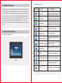
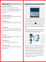
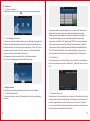
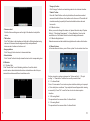
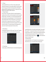
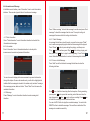
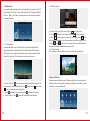
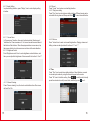
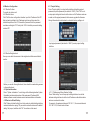
7" Intelligent Digital Video
Doorphone Indoor Unit
Product Overview .......................................1
Product Description ....................................1
Basic Function ...........................................2
UI Interface Introduction and Operation
Instruction ..................................................3
Installation Instruction ..............................18
Technical Specification ..............................19
TIP-DPH-INT7
USER MANUAL
www.tissmarthome.com
2.2 Icon Introduction
Product Overview
With the advance of technology and society, our daily life is stepping into
Name
Status Icon
Implication
the network era. The digital trend has swept through every industry as a
result of which the traditional building intercom products are developing
Night Mode
Indicate the working status of various
alarm detectors during nighttime.
Home Mode
Indicate the working status of various
alarm detectors during daytime at home.
Leave Mode
Indicate the working status of various
alarm detectors when no one is at home.
Message
Indicate unread messages.
Missed Calls
Indicate missed calls.
Network connected
Indicate the network connection is
normal.
Network disconnected
Indicate the device is not connected
with the outdoor unit.
Melody status
Indicate the melody ring tone is on.
Monitor
Click to enter monitor interface.
in a more digital, network-based, information-based and intelligent way.
It is no longer a pure system for confirming the identity of visitor, but also
a intelligent home platform which provides intercom, home security,
appliance control, information access and multi-media entertainment all
in one.
Product Description
2.1 Product Appearance
Call Management Unit Click to call Center Unit directly.
Figure 1
1
Call
Click to enter Call interface.
Menu
Click to enter Function Setting interface.
2
Basic Function
UI Interface Introduction and Operation Instruction
3.1 Digital Video Intercom Function
It is able to receive calls from outdoor unit, fence outdoor unit,
management unit or other networking terminal unit. Besides it can call and
activate two way video intercoms with all networking terminal unit and
management unit.
At first boot, the interface for inputting D code will appear:
3.2 Remote Unlocking Function
Users are able to release the electric lock of the outdoor unit and fence
unit by pressing UNLOCK button.
3.3 Monitoring Function
Users can monitor outdoor environment through the outdoor unit or fence
unit.
3.4 Owner Message
Before leaving home, users can leave messages to their families on the
terminal devices and receive visitors' messages on the outdoor unit as
well.
When there is no management center, according to the network topological
graph (in simple presentation, just simply connect stair unit to indoor unit
directly with a network cable), conduct address setting on indoor unit after
wiring. In D code input interface, press
to enter operation menu. Press
“System setting” and then “Project setting” to set IP address and room
number. Please refer to IP address and room number setting of Project
setting.
When a management center exists, the equipment can directly obtain the
address information and IP information already set from the management
center by entering D code. Simple structure is shown below:
3.5 Call Records
It is able to auto record the information and time of missed calls, received
calls, dialed calls for reference.
3.6 Info Check Function
It is able to check the messages sent by management unit.
3.7 Security Alarm Function
It can check whether the detectors in alarm zones are functioning normally
by Status Check function.
3
Firstly, add equipments on the server installed with Intelligent Building
Management Center Software. (For details please refer to "Intelligent
Building Management Center Software Instruction"). Then set up the
equipment address, IP information, export D code of the equipment, and
then enter D code into corresponding equipment. Prompts will appear to
indicate address information is successfully obtained. After that, the
equipment will automatically reboot, directly enter Main Menu and no
longer display interface of inputting D code.
4
4.1 Intercom
4.1.1 Intercom interface
In Main Menu interface, press “
” icon to enter intercom menu page.
4.1.2 Call Management Center
In “Intercom” interface or Main interface, press “Management center” icon
to directly call management center and then enter call waiting interface.
When the call fails, call failure prompt box will pop up. Press "OK" on the
prompt box to return to the “Intercom” interface, or it will automatically
return to “Intercom” interface after 5 seconds.
If management center answers the call, the following interface,
with "calling" and talking time in the middle, will pop up.
·“Hang up” button
Press this icon to end conversation and return to “Intercom” interface.
4.1.3 Call Other Residents
In “Intercom” interface, press “Other residents” icon to bring out dialing
interface.
5
Input room number on numeric keypad (if you call the user in the same unit,
please enter four digit room number; otherwise, please enter two digit
building number plus two digit unit number plus four digit room number ). If
the number entered is wrong, you can press backspace key to modify.
For example, to call Room 105, please enter "0105" on numeric keypad and
then you can press call icon to dial. When the call is answered, the status
column on the left of the screen will show the talking status and talking time.
The “Call” button at the bottom of the screen will change to “Hang up” icon.
You can press this button to end conversation and return to Call interface.
4.1.4 Call Record
In the call record menu, click “Call record” icon to enter call record interface.
Here you can check the records of “missed call”, “dialed call” and “received
call”.
4.1.5 Receive Video Call
When there is a call from outdoor unit or fence unit, the indoor unit will ring
and display the interface shown below. The background of the interface is
the scene captured the camera of outdoor unit or fence unit. The indoor
unit can release the door lock directly while it can also answer the call and
start video intercom and then unlock the door.
6
·Volume control
Click the Volume setting menu on the right of the interface to adjust the
volume.
·Talk button
Click “Talk” button in the interface and it will skip to Talking interface during
intercom. At the same time the ringtone will stop and speaker will
deliver sound of outdoor unit or fence unit.
·Hang up button
Click “Hang up” button to return to intercom interface.
·“Hang up” button
Click “Hang up” button to end monitoring and return to Intercom interface.
·“Switch” button
Press the “Switch” button on the top of interface, the monitor sound and
scenes will switch to those of next outdoor unit or fence unit. The switch will
circulate according to quantity of the actual installed outdoor units and
fence units.
4.2.2 Monitor Indoor
Before you monitor through the indoor unit, please follow the steps “System
Setting” ->“Monitoring Requirement” -> “Indoor Monitoring” to set up the
monitor device. Click Indoor Monitor to check the deployed cameras.
4.2.3 Monitor Neighborhood
Network cameras must be installed in neighborhood to achieve this function.
4.3 Alarm System
In the main menu interface, press “Alarm system” to enter alarm interface.
·Unlock button
Click “Unlock” button to directly release the door lock of corresponding door.
4.2 Monitor
4.2.1 Monitor Stair
Click “Monitor Stair” icon in Monitoring interface. You will be able to
monitor various sites installed with outdoor units and fence units. Also you
can switch over between different surveillance units.
Before using alarm system, please enter “System setting” -> “Project
setting” -> “Area define” to define the security areas to be set.
4.3.1 In Home Model
Press “In home model” icon in alarm system interface to bring out a prompt
of “arm delay time countdown”. A prompt interface will appear after arming
successfully. Press "Ok" or wait for 5sec to return to alarm system
interface.
4.3.2 Evening Model
The operation is the same as that of In Home Model.
4.3.3 Leaving Model
The operation is the same as that of In Home Model.
7
8
4.3.4 Disarm
In alarm system interface, press “off” icon to bring out disarm model
interface which requires you to input disarm password. Using the numeric
keypad on the screen to enter the password set disarm (default disarm
password is "0000", default hijack code is "0001"), and press "Ok" icon at
the bottom of the interface to disarm the system.
4.3.5 Disarm Password
Press “Off code” in alarm system interface to access disarm password
inputting interface, and then enter disarm password to enter the password
setting interface. In the interface, you can set the master password and
hijack code (hijack code is master password +1). Enter the old password
(default old password is "0000") into "Old pwd" bar on numeric keypad,
and then enter the new password you want to set into "New pwd" bar.
Re-enter the new password into "Sure pwd" bar and press “Ok” icon at the
bottom of the interface. If the interface prompts that the password has
been saved, it means the new password is set successfully.
4.3.6 Alarm Record
In alarm system interface, press “Alarm record” icon to enter “View alarm
record” interface and then you can view and sort out alarm records.
In model setting interface, three optional models including "In home model”,
“Evening model”, “Leaving model" will be shown at the top of the interface.
Press the model you want to set. "Setting" option represents arm delay time
and "Reporting" means alarm delay time. Click “on or off” button to turn
on/off the area. When the setting is done, press
icon at the bottom of the
interface to complete the setup.
4.3.8 Alarm Area State
In alarm system interface, click “Alarm state” icon to enter alarm area
status interface. Here you can check the status of all alarm areas.
4.3.7 Model Setting
In alarm system, press “Model setting” icon to enter model setting interface.
9
10
4.4 Information and Message
In the Main menu interface, press “Information” icon to enter Information
interface. There are two types of data: information and message.
Press “Visitor message” to check the message from visitor and press “Host
message” to check the message from the user. The way of sorting out
message is the same as that of sorting out information.
4.4.1 Total Information
Press “Total information” icon in Information interface to check all the
information and message.
4.4.2 Information
Press “Information” icon in Information interface to check public
announcement received and personal information.
4.4.3.1 Check Message
In message list interface, select the entry you want to view, press "Read"
icon to enter messages playing interface and the message will be played.
Press "Pause"
button to pause during the playing, and then press
“Play”
button to continue; press “Stop”
button to stop playing, and
then press “Play”
button to play from the beginning. Press “Return”
icon at the bottom of the interface to return to the message list interface.
4.4.3.2 Leave a Host Message
Press “Add” icon at the bottom of message list interface to enter the
following interface.
You can choose to display public announcement or personal information
through the top bar. Press an information entry, and it will be highlighted to
indicate that the message is selected. Information entry includes "message
title, message preview, date and status". Press "Read" icon to browse the
selected information.
4.4.3 Message
Press “Message” icon in information interface to enter message list
interface.
11
Press
icon, it will start recording after the beep tone. During recording,
you can press
icon to pause the recording, and at the same time, the
icon changes into
Press
icon to continue recording. Press
icon
to finish the recording and enter audition interface.
You can click PLAY button to play the recorded message. You could click
DELETE button to delete the message. There will be an indication if the
message is recorded successfully.
12
4.5 Multi-media
If you want to develop this function, to begin with you need to insert a TF
card into the TF card slot. Then create three files in TF including “Digital
Photos”, “Music” and “Video” in which photos, music and videos will be
saved respectively.
4.5.1 Digital Photo
In multimedia menu, press "Digital photo" icon to enter digital photo
displaying interface. Operation menu is at the bottom of the interface.
When there is no operation, the operation menu will automatically hide
itself after 5 seconds. Click the screen to bring out the menu.
a.Press “Auto Play”
icon, the system will automatically display all the
pictures one by one. Meanwhile, the icon
changes into
icon. Press
icon to stop continuously displaying.
b. Press to display previous photo, press to display next photo.
c. Tap the “Return” icon to return to multimedia menu interface.
13
4.5.2 Music Playing
a. Select “Music” icon in the menu. Press
icon to play music.
b. Press
to play previous song, and press
to play next song.
c. Click
to put a song on a loop and the icon will become
at the
same time. Click again to exit loop mode and songs will be played in turn.
d. Click
and
icon to turn up or down the volume with numbers
shown in the middle to indicate the volume level.
4.5.3 Video Playing
The operation of playing video is the same as that of playing music.
4.6 System Setting
In the main menu interface, press “System setting” icon to enter system
setting interface. System setting consists of display, sound, time, system
information, project setting, etc.
14
4.6.1 Display Setting
In system setting interface, press “Display” icon to enter display setting
interface.
4.6.1.1 Screen Saver
In “Screen saver” interface, there are 3 options including “blank screen”,
“date/time” and “free screensavers”. You can set screen saver wait time at
the bottom of the interface. When the equipment enters screen saver, tap
the screen or button to exit screen saver and return to the main interface.
4.6.1.2 Brightness Control
Press “Brightness control” icon to enter brightness control interface, and
then you can adjust the brightness of the screen with the buttons "+" and "-".
4.6.2 Sound
Press “Sound” icon to enter sound setting interface.
4.6.2.1 Ring tone setting
Press “Ring” icon to enter ring tone setting interface. Different music can be
selected to be ring tone and then press button "
" to save the modification.
4.6.2.2 Volume
Press “Volume” icon to enter volume setting interface. Ringing volume and
talking volume can be adjusted with buttons of "+" and "-"..
4.7 Time
Press "Time" icon to enter time setting interface. Select the time you want
to set and input number by using the numeric keypad on the screen.
Press "Ok" icon to finish the setting. Press
to modify month, directly
press the calendar to modify current date, and finally press
save it.
4.6.1.3 Screen Cleaning
Press “Screen cleaning” icon, the touch-controlled function of the screen
will be off for 30s.
15
16
4.8 Monitor Configuration
4.8.1 Monitor Outdoor
To monitor by outdoor unit.
4.8.2 Monitor Indoor
Click “Add” to enter configuration interface. Input the IP address of the IPC
that is already installed in the IP address input bar, and then select the
installation position of the IPC. Amend the “password” into the password
used when setting the IPC. Finally click “OK” to finish the process of adding
a indoor IPC.
4.11 Project Setting
Press “Project setting” icon to enter the interface of inputting project
password, input the password (the default is “3888”). Click “Ok” icon to
enter project setting interface to set the indoor unit's IP address and room
number, set the project password, define areas, upgrade the firmware
through the network, detect network, restore the factory settings, etc.
Input project password (the default is “3888”) to enter project setting
interface.
4.8.3 Monitor Neighborhood
Here you can check the cameras in the neighborhood that are available to
monitor.
Before you monitor the neighborhood, there should be a networking camera
in the neighborhood.
4.9 System Information
Press“System information”icon to bring out the following interface.System
information includes serial number of this equirement,IP address,MAC
address,software version,hardware version and manufacturer information.
4.10 Restore to Default Setting
Click “Restore to default setting” icon to the restore to default setting interface,
and an indication box saying “Do you want to restore the indoor unit to default
setting” will pop out, and then click “OK” to conform or click cancel.
17
4.11.1 IP Address and Room Number Setting
Press "Addr setting" icon in the project settings interface to enter the
address setting interface to set the local IP address-related information
and room number information.
For example, the gateway address is 192.168.1.1, the server address is
192.168.1.200, it can be set as follows.
18
Network address setting
·IP address:192.168.1.100
·Subnet mask:255.255.255.0
·Gateway address:192.168.1.1
·Server address:192.168.1.200
Room number setting
·Building no.:0101(Building 1 Unit 1)
·Room no.:0105 (Room 105)
·Extension doorbell no.:1
After setting, press "Ok" to save it. Press
to exit the system setting
menu, the equipment will automatically reboot. The configuration will take
effect after reboot.
Note: IP address should be different from other equipments within the
same network. In the same unit, indoor unit and the corresponding
stair unit should be set in the same network segment.
4.11.2 Password Setting
Press “Pwds setting” icon to enter project password setting interface to set
the project password.
4.11.3 Area Definition Setting
Press "Area define" icon in project setting interface, enter the area define
setting page to select the place, type, trigger way and state. Area location
includes gate, doors, bedroom, guest room, hall, window, balcony, kitchen,
study and bathroom. Sensor type includes infrared, magnet, smoke, gas
and emergency.Trigger way includes normal closed, normal open, 3-state
low level (the unit will alarm when it is in low level, equipment installation state
detection), 3-state high level (the unit will alarm when it is in low level,
equipment installation state detection).
19
4.11.4 Others
4.11.4.1 Factory Test
Press “Ok” icon of “Factory” and follow the indication to enter factory test
interface.
4.11.4.2 Network Test
Press “test” icon to test the connection status with gateway and server.
4.11.4.3 Restore Factory Test
Press “Ok” icon of “Restore factory” to bring out the prompt box displaying
whether to restore the factory setting. Reconfirm the prompt box, and then
press "Ok" icon to restore the setting. After that, the system will restart
automatically.
4.11.5.4 D-code Function
To activate or shut down the alignment code function.
20
Installation Instruction
Technical Specification
5.1 Topological Graph
High-level area
Multi-level area
Indoor unit
Alarm
Infrared
Smoke
Indoor unit
Switch
To next unit
Installation Method
Resolution
Screen
Touch Type
RingRing volume
Power Supply
Working Current
Working Temperature
Power Consumption
Outline Dimension
Switch
Wall-mounted (subject to the mold)
800x480
7'' TFT LCD (colored)
Capacitive touch
= 70dB
DC 12V/1A
< 550mA
-20℃~+60℃
< 6W
204 x 134 x 18.5mm
Switch
Switch
Outdoor unit
Outdoor unit
门口机
Outdoor unit
Management Center
CAT5 UTP
Fence Unit
Switch
Management
Center Unit
Router
Waterproof CAT5
FTP
Power Supply Wire
Management Center Server
Remote Control
3G WAP
5.2 Wiring Diagram
+
-
TIS-BUS
21
D+
D
GND
22