1
Project IST-511599
RODIN
“Rigorous Open Development Environment for Complex Systems”
RODIN Deliverable D31
Public Versions of Plug-in Tools
Editor: Michael Butler, University of Southampton
Public Document
7 September 2007
http://rodin.cs.ncl.ac.uk/
RODIN D31 Public Versions of Plug-in Tools
Contributors:
Colin Snook (University of Southampton)
Abdolbaghi Rezazadeh (University of Southampton)
Kriangsak Damchoom (University of Southampton)
Michael Leuschel (University of Düsseldorf)
Jens Bendisposto (University of Düsseldorf)
Olivier Ligot (University of Düsseldorf)
Apostolos Niaouris (University of Newcastle)
Thierry Lecomte (Clearsy)
Ian Oliver (Nokia)
2
RODIN D31 Public Versions of Plug-in Tools
Table of Contents
1
2
3
4
5
6
7
8
9
Introduction................................................................................................................. 4
U2B Plug-in ................................................................................................................ 5
2.1
Previous versions of UML-B: motivation for an independent metamodel......... 7
2.2
Overview of plug-in functionality ...................................................................... 8
2.3
Overview of plug-in integration........................................................................ 18
2.4
Impact of case study drivers ............................................................................. 20
2.5
Future work on UML-B .................................................................................... 20
2.5.1
UML-B as a metamodelling language .......................................................... 21
2.6
Conclusions....................................................................................................... 22
2.7
References......................................................................................................... 22
B2Rodin Plug-in ....................................................................................................... 23
3.1
Overview of plug-in functionality .................................................................... 23
3.2
Overview of plug-in integration........................................................................ 25
3.3
References......................................................................................................... 26
Brama Plug-in ........................................................................................................... 27
4.4
Overview of plug-in functionality .................................................................... 27
4.5
Overview of plug-in integration........................................................................ 31
4.6
References......................................................................................................... 32
Mobility Plug-in........................................................................................................ 33
5.7
Overview of plug-in functionality .................................................................... 33
5.8
Rodin case studies influence to the evolution of the plug-in ............................ 36
5.9
Overview of plug-in integration........................................................................ 36
ProB Plug-ins ............................................................................................................ 39
6.1
RODIN ProB Visual Animation Plug-in .......................................................... 39
6.2
RODIN ProB Disprover Plug-in....................................................................... 40
B2Latex Plug-in ........................................................................................................ 41
7.1
Overview of plug-in functionality .................................................................... 41
7.2
Overview of plug-in integration........................................................................ 41
7.3
Conclusions....................................................................................................... 41
Experiments in Model-based testing......................................................................... 42
8.1
Model-Based Testing using Scenarios and Event-B Refinements ................... 42
8.2
Testing from Nondeterministic Specifications ................................................. 43
8.3
References......................................................................................................... 45
Experiment in Code Generation................................................................................ 46
3
RODIN D31 Public Versions of Plug-in Tools
1
Introduction
RODIN Deliverable D31 consists of public versions of plug-in tools for the Rodin
Platform. The deliverable consists of the software along with this overview paper report.
In the previous plug-in deliverables from WP4 (D11 and D16) we described a mixture of
requirements on tools and tools that existed in stand-alone form. D24 consisted of
prototypes of plug-ins for internal use in the project. We have focused our effort on
integrating a small number of plug-ins on the platform over the last 12 months.
The public plug-ins that constitute D31 are
• U2B
• B2Rodin
• Brama
• Mobility Plug-in
• ProB
• B2Latex
The plug-ins can be downloaded from the following address:
http://rodin-b-sharp.sourceforge.net/
The Rodin platform must be installed before installing any of the plug-ins.
As outlined in Sections 2 to 7 of this report, these plug-ins provide powerful functionality
over and above the powerful modelling and proof functionality provided by the Rodin
Platform. A further significance of these plug-ins is that they demonstrate the feasibility
of extending the Rodin Platform in a way that appears seamless to the user. For example,
within the extended environment it is now straightforward to construct a UML-B model
that is then automatically translate it to Event-B. The resulting Event-B can then be
animated using the ProB plug-in, proved using the Platform prove facilities and printed
using B2Latex. All of this integration is facilitated by the architecture of Eclipse, on
which the Rodin Platform is built, and by the architecture of the Rodin database and user
interface.
In addition to the public plug-ins, research and prototype tool development was
undertaken on model-based testing and on code generation within the RODIN project.
The resulting prototypes were not sufficiently mature to be usable more widely but the
research will form the basis for future plug-in development. This work is outlined in
Sections 8 and 9 of this report.
4
RODIN D31 Public Versions of Plug-in Tools
2
U2B Plug-in
The UML-B described in this report is a new graphical formal modelling notation that is
based on UML and relies on Event-B and the Rodin Event-B verification tools. The new
version of UML-B is implemented in eclipse and is therefore platform independent and
closely integrated with the Rodin Event-B tools. UML-B is a plugin extension feature to
the Rodin Event-B platform and U2B runs as an eclipse builder so that Event-B is
generated and analysed automatically as soon as a UML-B model is saved.
UML-B provides a top-level Package diagram for showing the structure of, and
relationships between, components (machines and contexts) in a project. Contexts are
described in a context diagram which is similar to a class diagram but has only data
which is interpreted as constant values. The ClassTypes (equivalent to classes) may
subtype each other and have associations between each other. Axioms (given properties
about the constants) and Theorems (assertions requiring proof) may be attached to the
ClassTypes. Constants, axioms and theorems may also be given at the context level,
without attaching them to a ClassType.
Similarly, Machines are specified by a Class diagram. The associations and attributes
represent variables and events may be attached to the class to describe how those
variables change. Events can also be represented by the transitions on a statemachine.
The statemachine represents a variable whose type is the set of states in the statemachine
and transitions are guarded so that they are only enabled when the statemachine variable
is at their source state. As the transition fires it assigns the target state to the variable.
Additional guards and actions concerning other class attributes can be attached to the
transition. An alternative translation of statemachines is also available and can be selected
for a particular statemachine. In this translation, each state is a variable whose type is the
set of class instances. Transitions remove the current instance from the source state and
add it to the target state. The most suitable translation usually depends on the other
guards and actions attached to the transition. A class may have several orthogonal
statemachines similar to orthogonal regions in UML. Each orthogonal statemachine
represents behaviour in terms of transition events that can interleave since, unless
explicitly modelled in the transition guards, the ordering implied by a statemachine is
independent of any orthogonal statemachine. Statemachines may also be attached to the
states of another statemachine. This provides a hierarchical sub-state mechanism, similar
to that of UML.
Invariants (and theorems) may be attached to classes and states (as well as independently
at the machine level). For invariants that belong to a class, if they refer to the current
class instance (self) it is implied (and provided automatically in the B translation) that the
invariant applies to all such instance of the class. For invariants that belong to a state, it
is also implied that the invariant has an antecedent that the current instance is in that state.
For textual constraints and actions we use a notation, µB (micro B) that borrows from the
Event-B notation. µB has the following differences from Event-B: An object-oriented
5
RODIN D31 Public Versions of Plug-in Tools
style dot notation is used to show ownership of entities (attributes, operations) by classes.
Variables used in an expression can represent owned features of class instances (such as
attributes, associations or state diagrams). The owning instance is specified using the dot
notation. For example i.x refers to the value of the variable x belonging to instance, i.
When an expression is attached to a feature belonging to a class, the owning instance for
the current contextual instance is referenced using the reserved word, self. The value
represented by an expression i.x depends on the cardinality of the variable x. If it is a
function a single value is represented; if not, a set of values (corresponding to the
relational image) is represented. Since it is often useful to concatenate several of these
traversals, we may wish to traverse an association from a set of instances that were
returned by a previous expression. For this case, the dot symbol is replaced by a right
facing triangle ►.
If no instance or set of instances precedes a class feature, the expression gives the
complete class–wide value of the feature (i.e. the complete relation rather than the value
for a single instance).
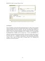
To give a flavour of UML-B, consider the specification of the telephone book in Fig. 2.1.
The classes, NAME and NUMB represent people and telephone numbers respectively. The
association role, pbook, represents the link from each name to its corresponding telephone
number. Multiplicities on this association ensure that each name has exactly one number
and each number is associated with, at most, one name. The properties view shows µB
conditions and actions for the add event. The add event of class NAME has the constructor
property set (not shown in Fig. 2.1) which means that it adds a new name to the class. It
non-deterministically selects a numb, which must be an instance of the class, NUMB, but
not already used in a link of the association pbook (see µB guard), and uses this as the
link for the new instance (see µB action). The remove event (which is a destructor of
class NAME) has no µB action; its only action is the implicit removal of self from the class
NAME. This specification is equivalent to the Event-B model shown in Fig. 2.2 and indeed
the U2B tool automatically produces the Event-B model of Fig. 2.2 from the UML-B
version in Fig. 2.1.
6
RODIN D31 Public Versions of Plug-in Tools
Fig. 2.1. UML-B Specification of a phone book
Fig. 2.2. Event-B specification of a phone book
2.1
Previous versions of UML-B: motivation for an independent metamodel
In previous work [SnBu06] we developed a specialisation of the UML called UML-B
using the profiling extension mechanism included in UML. That, initial, version of UMLB was implemented used the Rational Rose UML tool and included a translator U2B to
generate so called ‘classical B’ (B before Event-B). However, the degree of integration
between the tools was poor and unidirectional. Experience with the initial version of
UML-B indicated that the richness and semantics of UML could be misleading for
modellers. UML-B used a subset of UML features that were useful for translation into B.
However, users were confused over which features they should use and often complained
that a setting hadn’t done anything. Another problem was that sometimes experienced
7
RODIN D31 Public Versions of Plug-in Tools
UML users complained that the semantics of UML was not quite the same as that used by
UML-B.
For our initial attempt at the new Rodin UML-B we again used a profile. In UML 2.0, the
concept of profiles had been strengthened and was supported in eclipse by the UML2
project. We used properties attached to profile stereotypes to define all the features we
needed even where UML contains a similar concept. Only the bare diagram elements
from UML were used. The method was tested using Rational Software Architect [RSA]
which is based on eclipse and supports profiles implemented in UML2. This method was
an improvement on the previous UML-B. The specialisation was clearly demarked from
the basic UML notation leading to less confusion. Stereotypes were automatically applied
and profile features were entered in a separate view pane. However, there was a strong
feeling that the profile was an add-on and not an integral part of the notation. There was
still the problem that the main notation contained a lot of unused redundant modelling
concepts. Apart from the concern about usability and elegance of the modelling notation,
there was a great deal of redundant tooling supporting the unused UML and a dependence
on the eclipse UML2 project providing appropriate facilities to support our aims.
The profile extension mechanism is intended to be used when a relatively small
adaptation of UML is required. When the specialisation is more extensive, as in our case,
a new metamodel should be defined. The UML is defined by a metamodel that is
described using MOF (a small subset of UML for describing modelling notations). The
advantage of defining UML-B via an independent metamodel is that it can be designed to
the requirements rather than as an adaptation of something more general. Hence UML-B
is now a UML-like formal modelling language rather than a specialisation of the UML.
2.2
Overview of plug-in functionality
The UML-B modelling environment consists of a project creation wizard that creates and
initialises a UML-B project folder and provides and initial empty UML-B model. The
UML-B builder is associated with the project so that it runs automatically whenever
appropriate resources (files) are saved in the project. Four interlinked diagram types
(package, context, class and statemachine) are provided. The top-level package diagram
is opened with an empty canvas by the new UML-B project wizard. This canvas
represents the UML-B project. Other diagram types are linked and opened via model
elements as they are drawn on the various canvases. The diagrams are visual
representations of the underlying UML-B model (*.umlb file) and contain no modelling
information, only diagram layout. Diagrams can be generated automatically from the
model file albeit with a default layout.
8
RODIN D31 Public Versions of Plug-in Tools
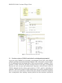
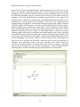
Fig. 2.3. Example package diagram
Package Diagrams
Package Diagrams are used to describe the relationships between top level components
(machines and contexts) of a UML-B project. The diagram shows the machines in a
UML-B project and the refinement relationships between them, the contexts and the
extension relationships between them and which contexts are seen by each machine. Fig.
2.3 shows an example of these relationships between two machines (blue) and two
contexts (yellow). Notice the properties view at the bottom of the perspective. This is
where the property details of model elements are configured and where error messages
will be reported. In this case context cx1 is selected in the drawing and the properties
view contains a button to (create, if necessary) and open the context diagram for cx1.
Context Diagrams
The Context diagram is used to define the static (constant) part of a model. This reflects
the use of contexts in Event-B. ClassTypes are used to define given sets of instances and
then to define constant attributes that are based on that set (i.e. lifted). For example, Fig.
2.4 shows a ClassType PERSON that has an attribute, id. The properties for the attribute
provide control over the cardinality features of the attribute. In this case, we wish all
instances of PERSON to have exactly one id and for that person’s id to be unique. Hence,
we have set the functional, total and injective properties. (Functional and total are default
values for attributes). Fig. 2.4 also shows the Event-B context that has been produced
from this UML-B context by the U2B tool. In the Event-B version of the context (as
shown in the upper right hand view pane), sets are denoted with a purple star icon,
constants with a yellow circle and axioms with a green star.
9
RODIN D31 Public Versions of Plug-in Tools
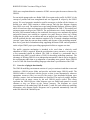
Fig. 2.4. Example Context diagram showing properties view of an attribute and Event-B translation.
Fig. 2.5 shows further features of the context diagram. An association, accounts, provides
a constant in exactly the same way that the attribute, id, did. The only difference is that
associations are shown graphically as a connection between two ClassTypes and do not
default to functional and total. Hence, UML-B simplifies the treatment of associations
compared to UML. UML-B associations are always uni-directional and contained by the
source whereas UML associations are uncontained independent elements that are
referenced by the two roles belonging to the two classes involved. This simplification
makes translation into Event-B easier by removing the full flexibility of UML
associations. However, since the UML approach would require multiple redundant
variables which would be very undesirable when proving consistency, the loss of
flexibility is desirable.
The ClassType, PERSON has the ClassType CUSTOMER as its superset. Hence it is translated
into a constant which is a subset of the given set, CUSTOMER. The ClassType, ACCOUNT
has its instances property set to accounts. The instances property provides a means to
model a ClassType from a set of instances defined elsewhere within the context. In this
example ACCOUNT is actually the set of link mappings in the constant association,
accounts. Hence, ACCOUNT corresponds to UML’s association classes. The mechanism is
more flexible than association classes since any expression resulting in a set can be used,
including predefined types and their derivatives such as N, P(N) etc. and expressions using
other features within the model, e.g. BANK x BANK. The Constant, interestRate, is
independent of any ClassType providing a mechanism for defining constants that are not
lifted by, or dependent on, any ClassType.
10
RODIN D31 Public Versions of Plug-in Tools
Fig. 2.5. Example Context diagram showing ClassTypes and their Event-B translation.
When a context extends a previous one, sets and constants may be added while the
previous ones are still accessible. For example, a new constant could use a ClassType
from the extended context as its type. Usually, this can be adequately achieved by
selection from a drop down list in the properties field of the new element. However, we
may wish to add new attributes to a previous ClassType. This could be achieved by
adding a constant and setting its type textually but the illustration of Class ownership that
is a key feature of UML-B would be lost. Therefore UML-B allows previous ClassTypes
to be extended in a new Context. The ‘Extended ClassType’ does not represent a new
model element and hence cannot be named. (Its diagram label is derived from the context
that owns the extended ClassType and the context to which it belongs). This allows us to
extend the ClassType with new attributes and associations representing new constants.
The old ClassType will be used when constructing their types. We also allow new
Axioms and Theorems to be added to the ClassType. An example of the representation of
an ExtendedClassType is shown in Fig. 2.6.
11
RODIN D31 Public Versions of Plug-in Tools
Fig. 2.6. Example Context diagram showing Extended ClassType with new attribute.
Class Diagrams
The class diagram is used to describe the behavioural part of a model. Classes represent
subsets of the ClassTypes that were introduced in the context. This subtype relationship is
explicitly defined in the class’ properties. The class’ associations and attributes are
similar to those in the context but represent variables instead of constants. For example,
in Fig. 2.7, the bank class has an association, accounts, with the account class which will
be translated into a variable, accounts, of type bank j account and initialised to 0.
Additional invariants giving the functional nature of the inverse relation and coverage of
the range, reflect the 1..1 cardinality at the source end of the association. The attribute,
balance, of class, account, defaults to a total function. A class invariant specifies that the
account’s balance must be greater than its overdraft limit, odlim, illustrating the
translation of the µB dot notation.
12
RODIN D31 Public Versions of Plug-in Tools
Fig. 2.7. Example Class diagram and its Event-B translation
The correspondence between an association’s multiplicity constraints (introduced in Fig.
2.5 but also applicable to associations between classes) and the constraints on the
resulting Event-B relationship is clear from the drawing tool. The multiplicity properties
are described using the usual mathematical terminology (functional, total, injective,
surjective) with the UML style multiplicity also shown and annotated automatically on
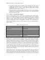
the diagram. Table 1 shows the full correspondences.
Classes may contain events that modify their attributes. An example was shown in the
overview given in section 3 (Fig. 2.1). Such events implicitly utilise a local variable that
non-deterministically selects a valid current instance of the class. This instance is referred
to via the reserved word self when referencing the attributes of the class. Constructors
and destructors add or remove these implicit instances from the current instances of the
class.
We have also found it useful to model ‘fixed’ classes where instances cannot be added or
removed. Many systems (e.g. embedded systems such as the FMS of case study 2) have
this, sometimes complex, static configuration. The use of generic UML-B models to
verify and validate complex static configurations is investigated in [SJP05].
Even in systems that are essentially object-oriented, there are often singular features
which do not require lifting to a class of objects. UML-B provides machine level features
(events, statemachines, invariants and theorems) to be placed on the class diagram canvas
without containment within a class. These features are translated directly to Event-B
13
RODIN D31 Public Versions of Plug-in Tools
without any of the class instance additions described elsewhere. A complete non-objectoriented model can be constructed in this way. Although there would be little benefit
from the class diagram, the package diagram overview of the project is still useful and an
orthogonal and hierarchical statemachine representation is available. This has been used
effectively by Åbo Akademi on case study 2.
Table 1. UML-B association multiplicities and their Event-B translation
UML-B association properties
multiplicity
surjecti
ve
injecti
ve
Description of Event-B representation
total
functio
nal
0..n Æ 0..n
1..n Æ 0..n
relation
*
Relation covering Bi
*
0..1 Æ 0..n
1..1 Æ 0..n
*
1..1 Æ 1..n
*
Relation covering Bi and inverse is function
*
Relation covering Ai
*
Relation covering Ai and Bi
*
*
Relation covering Ai and inverse is function
*
*
Relation covering Ai and Bi and inverse is function
*
0..1 Æ 1..n
Relation and inverse is function
*
0..n Æ 1..n
1..n Æ 1..n
*
partial function to Bi
*
partial surjection to Bi
*
*
partial injection to Bi
*
*
partial bijection to Bi
*
*
total function to Bi
*
*
total surjection to Bi
*
*
*
total injection to Bi
*
*
*
total bijection to Bi
0..n Æ 0..1
1..n Æ 0..1
*
0..1 Æ 0..1
1..1 Æ 0..1
*
0..n Æ 1..1
1..n Æ 1..1
*
0..1 Æ 1..1
1..1 Æ 1..1
(Ai and Bi are the instances sets of the classes)
*
As with contexts, we need a mechanism to add new attributes to an existing Class that is
already defined in the refined machines. Therefore UML-B allows existing classes to be
refined in a new Machine. Again, the ‘RefinedClass’ does not represent a new model
element and hence derives its label from the refined class and it’s containing machine.
New attributes, associations, events, statemachines, invariants and theorems can be added
to the RefinedClass. There are some translation differences to context however.
Extending contexts are purely superpositions and hence old elements are always available
in later extensions. Machines, however, may replace variables via data refinement.
Hence, the RefinedClass must be represented in the Event-B machine by re-declaring its
variable and initialisation (if it is a variable class). Similarly, we need to specify which of
the old attributes of the refined class are to be retained. UML-B allows the retained
attributes to be indicated by adding an ‘InheritedAttribute’ to a RefinedClass. The
translation of an InheritedAttribute involves re-declaring its variable and its initialisation.
The name and type of the InheritedAttribute cannot be changed except by going back to
the attribute or association where it was originally defined. Since, invariants of a refined
machine are visible in a refinement, no type invariant is generated for InheritedAttributes.
14
RODIN D31 Public Versions of Plug-in Tools
An example of a RefinedClass with inherited and new attributes is shown in Fig 2.8. A
new attribute, debits, and a new association, account_holder, have been added to a
RefinedClass, account, from machine, m1. Notice that the InheritedAttribute, odlim, is
selected and shown in the Properties window where only its inherits property can be
altered. The translation shows that invariants are only generated for the newly added
variables.
Fig. 2.8. Example Class diagram and its Event-B translation
15
RODIN D31 Public Versions of Plug-in Tools
Statemachine Diagrams
Statemachines attached to classes represent a variable of the class that partitions the
behaviour of the class in some way. For example, the statemachine, bal_state, of class,
account, partitions the behaviour of the account class into two states, black and red (Fig.
2.9). The transitions of a statemachine represent events with the additional behaviour
associated with the change of state implied by the transition. That is, the event can only
occur when the instance is at its source state and, when it fires, changes the state of the
instance to the target state. Each transition represents a separate event. As with events,
event variables can be added to the transition to provide a non-deterministically chosen
value to be used in the transition’s guards and actions.
Fig. 2.9. Example Statemachine diagram showing ancillary properties of a transition
In order to define the type of the state variable, bal_state, the translation needs a given set
that consists of the two states, black and red. This is defined in the implicit context for m1
as shown in Fig. 2.10.
Fig. 2.10. Translation of example statemachine into Event-B (data parts)
Invariants may be attached to the states as shown in Fig. 2.9. During translation, these
invariants are universally quantified over the class instances and constrained by an
16
RODIN D31 Public Versions of Plug-in Tools
antecedent as shown in Fig. 2.11. This provides an efficient mechanism for linking the
meaning of the states to other class variables.
Fig. 2.11. Translation of example statemachine into Event-B (state invariants)
The translation of a transition (for example, withdraw2 is shown in Fig. 2.12) is similar to
class events except that a guard for the starting state (source.state) and an action to move
to the target state (target.state) are added.
Fig. 2.12. Translation of example statemachine into Event-B (transition)
The transition from the starting state defines a constructor for the class. Hence the
translation (Fig. 2.13) selects an unused instance and adds it to the set of current instances
and initialises all the class variables for that instance. Similarly, the transition to a final
state is a destructor and removes the instance from the current instances and from the
domain of all the class variables.
Fig. 2.13. Translation of example statemachine into Event-B (constructor)
An alternative, semantically equivalent, translation of statemachines is provided and can
be selected per statemachine by setting a property of the statemachine in the properties
window of the interface. With this alternative translation, a variable is provided for each
state that represents the instances currently in that state. The choice of translation is
influenced by the model. For example, the alternative translation is useful when the
transitions are guarded by the number of other instances in particular states, since it is
then convenient to refer to the cardinality of a state. Fig. 2.14 shows the translation of the
same example statemachine given in Fig. 2.9 but with the alternative translation selected.
The states, red and black are represented as subsets of class instances and the event is
17
RODIN D31 Public Versions of Plug-in Tools
guarded by self e black. Two actions, leave_source and target_state are required to move self
from black to red.
Fig. 2.14. Translation of example statemachine into Event-B transition using alternative translation
2.3
Overview of plug-in integration
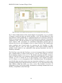
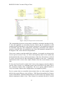
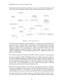
The abstract syntax of the structure of the UML-B language is given by a metamodel
using UML class diagrams with OCL constraints attached to some model elements. The
UML-B metamodel uses a small subset of UML’s class diagram features that is
equivalent to the OMG’s Metamodel Object Facility (MOF). Extensive use of
generalisation ensures that commonalities in UML-B model elements are defined. The
metamodel is a precise description of the abstract syntax of the UML-B language and is
used to automatically generate repository and editing utility code. Fig. 2.15 shows part of
the UML-B metamodel to illustrate the modelling style. Italicised classes represent
abstract model elements, instances of which can only exist via one of their subtypes. A
common base class, UMLBelement, provides an error marking scheme to all model
elements. A subtype of this base class, UMLBconstrainedElement provides a base for
elements that own constraints (axioms or invariants) and theorems. Note that the
metamodel does not define the syntax of predicates, merely representing them as a string
attribute of the UMLBPredicate class. The syntax of these strings relies heavily on that
of Event-B with a few modifications to suit the object-oriented features of UML-B.
UMLBnamedElement and UMLBnamedConstrainedElement add a name property. One
subtype of UMLBnamedConstrainedElement is UMLBconstruct which is further
subtyped into UMLBMachine and UMLBContext reflecting the main modelling
components of Event-B. Fig. 2.15 also shows that UMLBMachine can contain some
classes, UMLBabstractClass, which may be instances of UMLBClass or
UMLBRefinedClass. Fig. 2.15 only shows a small part of UML-B and omits many
features such as statemachines, variables and events that are contained within the
metamodel.
In some cases, where constructing a fully constraining graphical model is not possible,
OCL constraints are added to the model. An example is the metamodel for states and
transitions where a state that has the initial attribute set is not allowed to have incoming
transitions. It may have been possible to subclass states in some way so that initial states
were prevented from having incoming transitions. However, there is a similar need to
prevent final states from having outgoing transitions and it was felt that a graphical
depiction of this situation would complicate the model. OCL constraints are either
18
RODIN D31 Public Versions of Plug-in Tools
implemented within the graphical modelling tool to prevent invalid models being created
or are used in a pre-translation validation stage to ensure that the model is well-formed.
Fig. 2.15. The UML-B metamodel (part of).
The EMF (Eclipse Modelling Framework) [EMF] is an eclipse project that automatically
generates code for a model repository, model editor and API utilities based on an object
model. The EMF generated code provides utilities to programmatically create and
manipulate instances of the metamodel with serialisation provided in XMI. The GMF
(Graphical Modelling Framework) [GMF] is another eclipse project that, after a fair
amount of configuration, will automatically generate code for a graphical modelling tool
based on an EMF model.
The UML-B metamodel was imported into EMF in order to generate the eclipse plugins
necessary to support the UML-B modelling language. The GMF was then use to generate
the UML-B graphical modelling tool. Drawings created using the UML-B modelling tool
are saved as serialised UML-B model files. An eclipse ‘builder’ responds to changes to
these model files and translates them into a Rodin Event-B project. In order to do this it
uses the API of the Rodin database to create a Rodin Event-B project containing
machines and contexts and add Event-B elements to them.
When these Event-B constructs are saved by the U2B program, the Rodin verification
tools (also eclipse builders) automatically verify the Event-B model and report any errors.
A final stage, which is not yet complete, is to listen for these errors and annotate the
UML-B diagrams so that a user can work entirely in the UML-B environment and benefit
from the powerful static verification and prover technology provided by Rodin Event-B.
It is still expected that there will be proof obligations where the prover requires human
19
RODIN D31 Public Versions of Plug-in Tools
assistance to discharge. This requires the modeller to switch perspective to the Event-B
prover environment and to work in the Event-B notation. However, one of the primary
goals of Event-B is to achieve better rates of automatic proof so that these instances are
reduced.
2.4
Impact of case study drivers
UML-B has been used on CS2 by teams working at ATEC, UK and Åbo Akademi,
Finland. ATEC provided feedback on the pre-RODIN version of UML-B. The main point
raised by CS2 in the year one and year two assessment reports was that use of the action
and constraint language, uB, relied upon knowing details of the translation process. This
was mainly due to the translation of many-associations into functions to sets of instances.
This has been changed to translate to relations so that the action and constraint language
is simpler. In addition, the use of ‘self’ is now mandatory, whereas before it could be
omitted. However, further work is required to complete a self-contained notation.
More recently the case study has used the new version of UML-B. This has been
successful but has revealed for better support for refining class diagrams. This was
investigated at Soton as part of a PhD research project. The need for dummy ‘refined
classes’ in order to handle refinement of class features was decided. This feature has now
been added to UML-B.
Similarly, work on CS4 at Soton, required the use of ‘records’ which were refined by
context extension. Records are analogous to ClassTypes in UML-B. The ability to
‘extend’ ClassTypes in extended contexts was added to UML-B as a result of this case
study.
Work with ATEC on CS2 has indicated that UML-B would be useful as a metamodelling
language for defining tools via the EMF utilities used in the creation of UML-B. This is
reported in the section on Future Work, below.
2.5
Future work on UML-B
The following outlines the main areas which require further development.
• Errors reported by the Rodin platform should be annotated back to the UML-B
diagrams. Some initial work has been completed so that the generated Rodin
model elements have a pointer back to the UML-B element from which they were
created. Work was suspended on this feature because the problem reporting and
markup system of the Rodin platform was being re-worked.
• The U2B builder does not respond to deletion or name change deltas. This means
that, if a UML-B model construct (machine or context) is deleted or renamed the
Rodin equivalent construct remains in the Event-B project. A similar problem
exists when elements that have an associated diagram (e.g. statemachines) are
deleted or renamed.
• Some problems occur when several diagrams are edited simultaneously. Unsaved
changes to other diagrams can be lost when a diagram is saved.
20
RODIN D31 Public Versions of Plug-in Tools
•
•
2.5.1
The version of GMF used for UML-B is now superseded. The new version
contains many desirable features (e.g. the ability to collapse unused diagram
compartments). The new version of GMF cannot be adopted until the Rodin
platform is migrated to Eclipse version 3.3.
Additional features are planned to enable UML-B to be used as a meta-modelling
language and to be imported into EMF for tool creation. This is discussed in more
detail in the subsection below
UML-B as a metamodelling language
UML-B context diagrams provide a similar level of modelling facility as MOF (MetaObject Facility) [MOF] and can be used to define the abstract syntax of other modelling
languages or of a problem domain. Furthermore, UML-B context diagrams can contain
axioms to further constrain the abstract syntax when diagrammatic means are not
expressive enough and to impose well-formedness constraints. The correspondence of
UML-B context diagram elements to UML elements used in our meta-modelling is
shown in Table 2.
Table 2. Comparison of UML-B to MOF
UML-B
ClassType
not supported
Supertype
not supported
Attribute
Association
not supported
Instances (enumeration of a ClassType)
Axioms
UML
Class
Abstract Class
Generalisation
Multiple Generalisation
Attribute
Association
Containment
Enumeration
Constraints
Abstract Class – An abstract class may only have instance via its subtypes. Additionally,
the subtypes are assumed to be non-overlapping. To support these concepts we propose
adding a boolean property, abstract, to UML-B classifiers (Class and ClassType) which,
when true, will cause the U2B builder to generate an invariant, axiom or theorem that the
abstract class is the union of its subtypes (or if it has no subtypes, then it must be empty).
A theorem is generated instead of an axiom, when the subtypes have stronger constraints
on their instances which could conflict. We view the disjointness of the subtypes as a
separate issue and propose to add a second boolean property, disjoint, which, when true
will cause the U2B builder to generate invariants, axioms or theorems that each pair of
subtypes is non-overlapping.
Multiple Generalisation – We propose to relax the constraint that a UML-B classifier can
only have one supertype. Each supertype defined will result in an invariant, axiom or
theorem defining the appropriate subset relationship. The modeller will need to take care
that all supertypes have a common parentage otherwise a typing error will be generated
21
RODIN D31 Public Versions of Plug-in Tools
by the Rodin static checker. A theorem that the subtype is not empty will also be
generated to ensure that nonsensical models with multiple types cannot be generated.
Containment – This feature is mainly of significance for implementation. In modelling
terms its only significance is that the contained instances cannot exist without the
container instance and therefore should be destroyed with it. We propose to add a boolean
property, contained, to the UML-B property meta-class to indicate whether the attribute
values should be destroyed with the owning instance. (This will have no effect unless the
attribute type is a UML-B classifier).
2.6
Conclusions
The advantages of moving away from a UML extension (profile) to a completely new
metamodel are that the language is more suitable and elegant for expressing Event-B
modelling concepts. The full expressivity of UML is largely redundant and can confuse
users. A profile would rely heavily on well-formed ness constraints, whereas these are
mostly built into the UML-B metamodel. UML-B still retains sufficient commonality
with UML for the main goals of approachability to be attained by industrial users.
UML-B provides a fully integrated graphical front end for the Event-B modelling
language. UML-B has similarities with UML that make it more approachable for users
that are used to using UML. Since UML-B automates the production of many lines of
textual B, models are quicker to produce and hence exploration of a problem domain is
more attractive. This assists novices in finding useful abstractions for their models. We
have found that the efficiency of UML-B in quickly generating large amounts of textual
formal B and its ability to divide and contextualise small µB predicates and expressions
assists novices who would otherwise, rightly or wrongly, be deterred from writing formal
specifications. Furthermore, the new event oriented UML-B with its strong integration
with the Rodin Event-B tools is gaining acceptance as a useful visual aid even with
experienced formal methods users.
2.7
References
[EMF]
[GMF]
[MOF]
[SnBu06]
[SPJ05]
[RSA]
The Eclipse Modelling Framework Project, http://www.eclipse.org/modeling/emf/?project=emf
The Eclipse Graphical Modelling Framework, http://www.eclipse.org/gmf/
OMG’s Meta Object Facility, http://www.omg.org/mof/
C. Snook and M. Butler, UML-B: Formal modeling and design aided by UML, ACM Transactions on
Software Engineering and Methodology (TOSEM), Volume 15 , Issue 1 (January 2006) pp. 92 – 122,
2006
C.Snook, M. Poppleton and I. Johnson, Rigorous engineering of product-line requirements: a case study
in failure management, submitted for publication.
Rational Software Architect,
http://www-306.ibm.com/software/awdtools/architect/swarchitect/index.html
22
RODIN D31 Public Versions of Plug-in Tools
3
B2Rodin Plug-in
The B2Rodin tool allows reusing existing B models within the RODIN platform. Such
event B models should comply with [1]. The B2Rodin tool is reachable at the update site
http://www.bmethod.com/html/outils_en.html.
Since D16, the B2Rodin plug-in has been improved, documented and closely integrated
to Brama and to CompoSys (a Rodin plug-in that has been developed along side the
project and experimented during industrial projects). B2Rodin has been experimented
during CS2, CS4 and CS5.
3.1
Overview of plug-in functionality
B2Rodin translates event-B based models, complying with [1] and parsable with Atelier
B/ B Compiler, into RODIN models. This means than not all operations provided by the
B language [2] are authorized when writing an event-B model.
The B model to translate is composed of:
- an abstraction, contained in a machine file (*.mch),
- zero, one or multiple, successive refinements, contained in refinement files (*.ref).
Optionally, Writing an event-B model into *.sys files in order to get the « split » and «
merge » feature is recommended. Then, from the *.sys files, another tool called Evt2B
allows the translation into Atelier B compliant files (*.mch and *.ref).
The output of the B2Rodin tool is a set of:
*.bum files, containing the models (original abstract machine and refinements);
– *.buc files, containing the contexts of the model (sets and constants)..
–
Prior to any translation, Atelier B compliant files need to be decorated with extra
information, to introduce event B semantics: pragmas.
23
RODIN D31 Public Versions of Plug-in Tools
A pragma is a piece of information, inserted as comment in the source code, needed by
B2Rodin to be able to link events and variables between a refinement and its abstraction.
Several pragmas are available:
•
Initialisation pragma
The initialization pragma indicates which variable or formula of the refinement is
able to remove the indeterminism of an initialisation substitution. The variable or
the formula is called a witness.
•
Variable pragma
The variable pragma indicates which variable or formula of the refinement is able
to remove the indeterminism of a substitution or an ANY. The variable or the
formula is called a witness.
•
Refinement pragma
24
RODIN D31 Public Versions of Plug-in Tools
The refinement pragma indicates which event of the abstraction an event of the
refinement refines. The pragma is written into a commentary before the concerned
event of the refinement in the *.ref file.
•
Include/Exclude pragma
Given a refinement and all its upper abstractions, the include pragma indicates
which events will be translated into the *.bum files.
Given all the upper abstractions of a refinement, the exclude pragma indicates
which events will be removed from the *.bum refinement associated file and all
further refinements. They must be written at the beginning of the OPERATION
clause. Once an event is included, it is implicitly copied in the lower refinement
unless it is excluded. It's not possible to exclude an event that has not been
included in an upper refinement. It's not possible to include an event that has been
excluded in an upper refinement.
The generation process is initiated with the model we would like to transform and the
level of refinement we would like to start from. A refinement column can be partly or
completely translated, the abstract part of the model being always part of the translated
files. For each *.mch or *.ref file, a bum file is generated. If needed, a *_ctx.buc file
(associated context) is generated. If a refinement introduces no new set or constant, the
associated bum model just uses the previous context model declared. On the contrary, the
bum model adds its own partial context and sees the context of its abstraction. The
generation process overwrites existing *.bum and *.buc files, if any.
3.2
Overview of plug-in integration
B2Rodin is a plug-in, contributing to import wizard and to help categories. The tool is
organized in several layers:
- the core, developed in C++ as an extension of the B Compiler / Decompiler;
- the finalizer, developed in xsl, for applying normalizing rules;
- the plug-in interface, developed in Java, connecting the core to the various Eclipse
and RODIN services;
- the help services, written in xml and html.
25
RODIN D31 Public Versions of Plug-in Tools
This plug-in is completely integrated within the Eclipse Platform and may be updated
online with the update site feature.
B2Rodin is also integrated in:
- Brama plug-in (automatically invoked when trying to animate a B specification)
- Composys plug-in (invoked when importing Atelier B format model and
dictionary).
3.3
[1]
[2]
References
MATISSE: The event B reference manual,
http://www.atelierb.societe.com/ressources/evt2b/eventb_reference_manual.pdf
B Language Reference Manual 1.8.5 ,
http://www.atelierb.societe.com/ressources/manrefb.185.fr.pdf
26
RODIN D31 Public Versions of Plug-in Tools
4
Brama Plug-in
Brama is a tool for animating event B models, with two
objectives:
- enable the debugging of a multi refinement level model
to get convinced that the model behaves as expected,
- show a B model in a way that it becomes
understandable by a non specialist, thus able to be
validated by third party.
A dedicated website has been set up and is reachable at
http://www.brama.fr/index_en.html.
Since D16, Brama has been extended (better support of event B expressions and
predicates, better animation capabilities, man-machine interface improvement),
documented and experimented during industrial projects (results are presented in [1], [2],
[4], [5] and [6]).
4.4
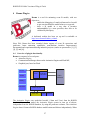
Overview of plug-in functionality
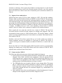
Brama is composed of several parts:
• Animation Engine,
• Communication Manager between the Animation Engine and Flash MX,
• Graphical part, based on Flash.
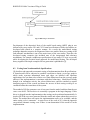
Driver
Views
Api: create, execute, modify
Core
Predicate
evaluator
Rodin
Database
History
Scheduler
Flash server
Flash MX
BFlash BSocket
The Animation Engine uses unchecked models (*.bum and *.buc) from the RODIN
database. From such a model, the Animation Engine creates its own set of objects,
independent from the RODIN database, by using the predicate evaluator. The Animation
Engine doesn’t listen to RODIN database modifications and behave independently. When
27
RODIN D31 Public Versions of Plug-in Tools
an animation is initiated, a picture of the model is taken and used for the rest of the
animation. Further modification of the underlying model has no effect on the animation,
until it is stopped and restarted. The Animation Engine is multi-threaded and can be
commanded via a set of commands.
The Communication Manager is responsible for sending and receiving
information/commands from/to Animation Engine/Flash-based graphical part. This
communication part is socket-based.
Messages from Animation Engine to Graphical Part are:
• event fired,
• new variable value.
Messages from Graphical Part are:
• event played,
• new variable value displayed,
• user interaction.
The graphical part is a Flash-based animation, connected to the Communication Manager
and exchanging XML flows. It is developed using FlashMX. Animations are set up
independently then connected to the underlying model, by specifying specific behavior
upon reception of commands. The decoding routines, transforming XML flow in Flash
commands, are common to all Flash animations using the Animation Engine.
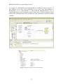
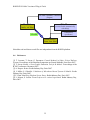
The tool provides several services which are exemplified on the following pictures:
•
Display the structure of a RODIN model
While animated, the several refinement levels are showed in columns. The most
abstract model is display on the right, the successive refinements are ordered from
right to left. Boxes represent events and arrows represent refinement links.
Green boxes are put for events that can fired, red boxes for events that can’t be
fired.
28
RODIN D31 Public Versions of Plug-in Tools
•
Debug a RODIN model
This view allows to:
o fire events (the ones associated with a check box). For example, in the
following picture, INITIALISATION and FRONT_MOVE_1 can be
triggered. In case of non-deterministic choices substitution, the formula
evaluator tries to find a correct valuation for variables. In case of failure,
the user is asked to enter a correct value. Main requirement is to keep user
interactions as low as possible;
o sort events according to their name (ascendant, descendant), to their guard
(open or closed first);
o display values of variables;
o check new variable value against the invariant;
o apply new values to the model;
o export a model, including scenarios (sequence of events, explicit
valuations from user) as a stand alone animation.
29
RODIN D31 Public Versions of Plug-in Tools
•
Manage history:
This view allows to:
o trace event execution,
o backtrack execution,
o save scenario,
o restore scenario.
•
Schedule events:
In some cases (reflex behavior for example), we would like to have events fired
automatically without user interaction. For that, schedulers may be explicitly
defined, indicating which event(s) to trigger automatically and what delay (in ms)
to apply once such an event is enabled. Those schedulers are declared and defined
in scheduler.xml file, as showed below.
•
Observe predicates:
Animation may require extra information/computation. Predicate evaluation
capabilities have been added. Predicates are defined in the observer.xml file and
messages are sent to the Communication Manager when a predicate valuation
changes.
30
RODIN D31 Public Versions of Plug-in Tools
•
Constants valuation:
Animation engine requires that all constants and sets to be valued. B2Rodin
provides means to import existing B models, valuating constants and sets with extra
information inserted in model as pragma. Brama has also a new editor window to
provide values for models completely developed within Rodin.
4.5
Overview of plug-in integration
Integration in the RODIN platform requires having access to bum and buc files
(unchecked models) in read-only mode. Brama can’t modify the RODIN model. Brama
is working on a stable RODIN model: further modification of a model is not taken into
account in the animation when initiated.
The Brama tool is also connected to B2Rodin, according to the following schema, as
B2Rodin provides sets and constants valuation required by Brama.
31
RODIN D31 Public Versions of Plug-in Tools
Sets and constants valuation
(Pragma)
Schedulers
B models
(.mch, .ref files)
(events fireable automatically
with delay)
Observers
(predicates)
b2rodin
Rodin models
(.bum, .buc files)
Scheduler.xml and observer.xml files are independent from the RODIN platform.
4.6
References
[1] T. Lecomte, T. Servat, G. Pouzancre: Formal Methods in Safety Critical Railway
Systems. Proceedings of the Brazilian Symposium on Formal Methods, Ouro Preto 2007.
[2] T. Servat: Brama: A New Graphic Animation Tool for B Models . Proceedings of the
B’2007 conference, Besancon 2007.
[3] A. Requet: Brama. Rodin Industry Day, Paris 2007.
[4] J. Millot, S. Gabrielle: Validation of Microkernel-based Systems B Models. Rodin
Industry Day, Paris 2007.
[5] F. Patin: Modelling Platform Screen Doors. Rodin Industry Day, Paris 2007.
[6] L. Mussat, S. Loison: From Grafcet to B: a mixed experiment. Rodin Industry Day,
Paris 2007.
32
RODIN D31 Public Versions of Plug-in Tools
5
Mobility Plug-in
As planned in the original project proposal, the mobility plug-in was to be developed and
primarily evaluated in the context of RODIN’s Ambient Campus case study. As a result
our work on the Petri net based model-checking has been conducted in close cooperation
with this case study. Having said that, it is clear that the notation (and so input to the
mobility plug-in) will be based on concepts and constructs coming from (or being based
on) Event B, KLAIM and the existing work on model checking π-calculus [3-8]. Under
the title ‘Mobile B Systems’ a high level programming notation has been developed
during the second year of the project for the specification of mobile applications.
Furthermore, it provides structured operational semantics through a set of rewriting rules.
Finally, a translation was described from the programming notation to a class of high
level Petri nets which preserves behavioural properties of mobile applications and, at the
same time, makes explicit causal relationships between events involved in executed
behaviours.
The work on ‘Mobile B Systems’ has reached the public version plug-in implementation
phase, and the folder accompanying the submission contains the plug-in implementation,
a user manual, some tutorial material for the first time users and documents explaining
the main technical details.
5.7
Overview of plug-in functionality
The key components of the Petri net based mobility plug-in are as follows:
• RODIN Platform providing the Event-B specification of our model;
• Editors allowing the user to input/edit process algebra expressions corresponding
to the distribution and behaviour model together with the scenario part of the
agent modelling language
• Translator taking as input Event-B specification and process algebra expressions
and providing as output the ‘Mobile B Systems’ programming notation;
• Translator from the ‘Mobile B Systems’ notation to high-level Petri nets;
• Unfolder for deriving a finite prefix of the unfolding of the translated Petri net;
• Verifier which establishes, by working with the finite prefix, whether the
necessary properties of the original input hold.
• Animator where the output of tool (error traces), together with the complete
model of the specification can be visualised.
Translators are in place to ensure the combination of the Event-B notation with the
process algebra expression. There are two key issues one needs to consider when building
such translators. The first is a behaviour preserving translation of the combined
specification into a high-level Petri net. The second issue is that the resulting high-level
Petri net (to be more precise it is an M-net), must be accepted as input from the modelchecking engine based on net unfolding. The translation from the modelling language to
the high level net input to the model checker is completely automatic and hidden from the
user. The full theoretical details of this translation are now being prepared for publication,
first as a technical report.
33
RODIN D31 Public Versions of Plug-in Tools
The Mobility plug-in appears in the platform in two places. First, there is a ‘Mobility’ tab
has been added to the central editing window of the platform containing the following
elements:
• An Editor for the distribution model of the agent modelling language.
• An Editor for the behavioural model of the agent modelling language.
• An Editor for the scenario part of the agent modelling language.
• A Results window containing the output of the automatic model checker for the
specific model.
• The Animator for animating mobile agent systems.
Furthermore, two buttons have been added in the main toolbar that control the behaviour
of the plug-in. The first one puts the tool in the deadlock checking mode, while the
second invokes the invariant checker.
The user starts by creating an Event-B model of the specification. Then the user selects
the ‘Mobility’ tab and adds the necessary process algebra expression describing the
distributed system composed of agents. It ‘guides’ the execution of the Event-B model
quite similarly to the ProB+CSP case. The process algebra expressions added using the
three editors are saved in a file which is created and managed by the RODIN platform
database. In order to save these expressions the corresponding ‘Apply’ button must be
34
RODIN D31 Public Versions of Plug-in Tools
pressed. Once all the corresponding process algebra expressions are in place, the user can
invoke the automatic verifier by pressing one of the two buttons in the main toolbar
depending on the required functionality. Once one of the controlling buttons is pressed
the following (automatic) steps are executed. The first step is the invocation of the two
translators. Any errors found during the translation (and actually in every stage of the
mobility plug-in workflow) are logged in the created RODIN database file and the user is
informed via a pop-up window at the moment. If no errors were found during the
translation then it is possible to run the model checking engine starting with the execution
of PUNF unfolder. Following the successful creation of the high level Petri net prefix,
MPSAT verifier can be invoked, the output of the verifier will also be stored with the
help of the RODIN database to the process algebra expression file and the user will be
informed. Depending on which of the two controlling buttons is pressed, the model
checking engine can perform two different and complementary tasks, namely checking
for deadlock freeness and detecting invariant violations in the specification. In both cases
in the event of an error discovery, the engine is capable of providing feedback that can be
used for debugging. The error trace comes as a list of transitions’ names of the high-level
Petri net (or to be more precise the prefix of the Petri net). In most cases this type of
feedback is not particularly useful to the user (especially users with no Petri nets
experience). In order to improve the functionality of the tool, the ‘translator’ component
used to obtain the high level net has been programmed to assign meaningful names
(matching names from the modelling language specification) to each transition.
35
RODIN D31 Public Versions of Plug-in Tools
Following the 30M submission of the internal version of this plug-in and our plans for
future work at that stage, we enhanced the functionality of the plug-in in several ways.
During these 6 months we have made radical user interface changes to the plug-in. At the
moment the plug-in is properly integrated and is following the user interface style of the
RODIN platform. Moreover, the handling of error messages is now treated in a more
systematic way and the user is receiving better quality feedback from the platform. To
further enhance user’s ability to understand and handle errors, we provided an animator
that is connect with the output of the verifier. With the help of the animator the user can
not only animate a ‘Mobile B system’ but also can visualise the obtained error messages.
Finally, significant progress has been made on the algorithmic side of the plug-in. Several
of the limitations on month 30 version of the project have been alleviated. For example,
we extended the syntax of allowed process algebra expressions, making it possible to
specify more realistic execution scenarios. This will involve an explicit support for tail
recursion, and a possibility of specifying priority levels of atomic actions.
5.8
Rodin case studies influence to the evolution of the plug-in
The mobility plug-in will be used by the Ambient Campus (CS5) case study. Actually,
this case study was the main source of requirements used for the building of this tool.
The feedback received from the case study drove the development and the addition of
features in the tool. Based on the development approach used in the building of the plugin, it is possible to model check a pure Event-B specification (deadlock detection and
invariant violations) for free. As a result it is also possible for every case study that uses
the ProB model checker to experiment with the mobility plug-in as well. At this point, we
should mention that since we were working closely with the Ambient Campus case study,
we support only the Event-B portions that were necessary for this case study.
5.9
Overview of plug-in integration
As mentioned in the outline the way of integrating our work with the other parts of the
platform is through the ‘Mobile B Systems’ programming notation. It should be stressed
that this language is not used as an input for the plug-in but rather serves as the
middleman. In this section, we will present the modelling language together with a small
example. More details about the modelling language including its structural operational
semantics and the complete translation to high level Petri nets can be found in [1, 2].
This way it will become obvious how we managed to combine Event-B notation coming
from the platform with a process algebra giving mobility characteristics to the model.
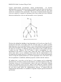
The modelling language specifications, called scenarios, are of the following form:
begin_scenario
l1 ... lk
rl1 ... rlm
ag1 = new(rl1’) … agn= new(rln’)
E
end_scenario
(locations)
(roles)
(agents)
(process expression)
36
RODIN D31 Public Versions of Plug-in Tools
In the above, it is assumed that li ≠ lj, rli ≠ rlj and agi ≠ agn, for all i ≠ j; and that
rl’i ∈ { rl1,… , rlm }, for all i.
As an example of the above, let us consider
ROLE Drinker
BODY
order = serve • ();
drink = skip
ROLE Pub
VARIABLES int:beer = 0
INVARIANT beer ∈ 0…10
BODY
serve = IF
beer >0
THEN
beer:= beer – 1;
drink • ()
END
SYSTEM
LOCATIONS pub1, pub2
INVARIANT beer@Pub • drinker@Pub
AGENTS
Student(drinker) := move(pub1).order;
Pub(pub) := move(pub1).‹beer@pubC<3›move(home);
END
The process expression describes a distributed system composed of agents, each agent
being an instantiation of a role. Its general format is
ag1:pa_act11. … .pa_act1m1.nil ||…|| agk:pa_actk1. … .pa_actkmk.nil
where the agi ’s are agents and pa_actij ’s are process algebra actions.
A role specification describes a set of events and actions which are procedures that
update role variables and initiate further computations. A role event is invoked by the •
(trigger) statement with suitable arguments supplied by a calling agent. In our
example, the action order in the Drinker role triggers event serve in role Pub which in
its turn may trigger Drinker 's event drink. An action is invoked from within a process
algebra expression, with constants or role variables as parameters. An action invocation
may result in a chain of event invocations corresponding to communication between
roles.
Executing move(l) changes the current locality of an agent, and the function number
(rl , l) returns number of agents associated with the role rl in the locality l.
The process expression is constructed from basic actions, which can be of one of the
following forms:
• move(l) moves the current agent (i.e., that labelling the sequential sub-expression
in which the action appears) to location l.
• migrate(l) moves the current agent to location l provided that in its current
locality there is no other agent which would want to trigger one of the events in
ag.
• act(ag,d) calls action act in agent ag with the actual parameters d.
37
RODIN D31 Public Versions of Plug-in Tools
•
〈bool〉 is a guard, where bool is a well-formed Boolean expression.
In addition to that we use prefix and (at the topmost level) parallel composition.
References:
[1] A.Iliasov, V.Khomenko, M.Koutny, A.Niaouris and A.Romanovsky: Mobile B
Systems. Technical Report, School of Computing Science, Newcastle University (to
appear in October 2007)
[2] A.Iliasov, V.Khomenko, M.Koutny, A.Niaouris and A.Romanovsky: Mobile B
Systems. Proceedings of the Workshop on Methods, Models and Tools for Fault
Tolerance, Oxford 2007. Technical Report 1032, School of Computing Science,
Newcastle University. (Jun 2007) 17-26.
[3] R.Devillers, H.Klaudel and M.Koutny: Petri Net Semantics of the Finite pi-calculus
Terms. Fundamenta Informaticae (2006)
[4] R.Devillers, H.Klaudel and M.Koutny: A Petri Translation of π-Calculus Terms.
Proc. ICTAC (2006)
[5] R.Devillers, H.Klaudel and M.Koutny: A Petri Net Semantics of a Simple Process
Algebra for Mobility. Electronic Notes in Theoretical Computer Science (2006)
[6] R.Devillers, H.Klaudel and M.Koutny: Modelling Mobility in High-level Petri Nets.
ACSD (2007)
[7] A.Iliasov, V.Khomenko, M.Koutny and A.Romanovsky: On Specification and
Verification of Location-based Fault Tolerant Mobile Systems. Proc. WREFT (2005
[8] V. Khomenko, M. Koutny and A. Niaouris: Applying Petri Net Unfoldings for
Verification of Mobile Systems. Proc. MOCA (2006)
38
RODIN D31 Public Versions of Plug-in Tools
6
ProB Plug-ins
The developers of the ProB toolsuite for B at the University of Düsseldorf have
developed two RODIN plug-ins based on ProB. Both of these are briefly outlined here
and are described in more detail in the following papers:
1. Jens Bendisposto, Michael Leuschel. A Generic Flash-based Animation Engine
for ProB. B 2007: Formal Specification and Development in B, 7th International
Conference of B Users, Besançon, France, January 17-19, 2007. Springer LNCS
4355 pp. 266-269, 2007.
2. Olivier Ligot, Jens Bendisposto, Michael Leuschel. Debugging Event-B Models
using the ProB Disprover Plug-in. Proceedings AFADL'07, June, 2007
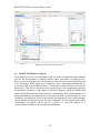
6.1
RODIN ProB Visual Animation Plug-in
Writing a formal specification for real-life, industrial problems is a difficult and error
prone task, even for experts in formal methods. In the process of specifying a formal
model for later refinement and implementation it is crucial to get approval and feedback
from domain experts to avoid the costs of changing a specification at a late point of the
development. But understanding formal models written in a specification language like B
requires mathematical knowledge a domain expert might not have. We have developed a
new, improved method to visualize B Machines using the ProB animator. We have
implemented this method as a plug-in to the open source Eclipse platform. We also
support Event-B models developed in the new Rodin platform. Our new tool offers an
easy way for specifiers to build a domain specific visualization that can be used by
domain experts to check whether a B specification corresponds to their expectations.
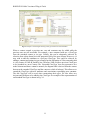
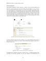
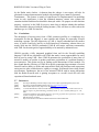
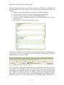
The screenshot below illustrates our plug-in in action, animation a Huffman decoder
model developed by another partner of the project (Southampton).
39
RODIN D31 Public Versions of Plug-in Tools
Fig. 6.1. Screenshot of ProB Animation Plug-In
6.2
RODIN ProB Disprover Plug-in
The B-method, as well as its offspring Event-B, are both tool-supported formal methods
used for the development of computer systems whose correctness is formally proven.
However, the more complex the specification becomes, the more proof obligations need
to be discharged. While many proof obligations can be discharged automatically by
recent tools such as the RODIN platform, a considerable number still have to be proven
interactively. This can be either because the required proof is too complicated or because
the B model is erroneous. In this paper we describe a disprover plugin for RODIN that
utilizes the ProB animator and model checker to automatically find counterexamples for a
given problematic proof obligation. In case the disprover finds a counterexample, the user
can directly investigate the source of the problem (as pinpointed by the counterexample)
and she should not attempt to prove the proof obligation. We also discuss under which
circumstances our plug-in can be used as a prover, i.e., when the absence of a
counterexample actually is a proof of the proof obligation.
40
RODIN D31 Public Versions of Plug-in Tools
7
7.1
B2Latex Plug-in
Overview of plug-in functionality
B2Latex is a simple plugin that converts Event-B models developed in the Rodin
platform into Latex. This enables models to be printed for documentation purposes. Any
comments in the Event-B models are also carried over to the Latex version and any Latex
commands can be used in the comments for interpretation by a Latex processor.
Use of the plug-in is very easy. After installation an ‘L’ button appears on the menu bar
in the Event-B perspective. The users select the Machine or Context they want to
translate to Latex and then presses the L button. A Latex file will then be generated in a
folder named Latex in the project directory of Event-B. This generated file is then
processed by Latex in the usual way.
7.2
Overview of plug-in integration
The integration with the platform is quite straightforward. The elements of an Event-B
model are accessed from the Rodin database using the Rodin API in much the same way
as the on-screen pretty-printer of Rodin. The user interface extension simply involves
adding an ‘L’ button which calls the translator on the currently selected context or
machine when invoked.
7.3
Conclusions
B2Latex was developed with less than 2 weeks of effort and is a nice example of how
straightforward it can be to extend the functionality of the Rodin platform. The plug-in
was used extensively in the CDIS case study (CS4).
While Latex2B does support the full Event-B language as currently implemented in the
Rodin platform, it does not provide much flexibility in terms of how the generated
document is structured. Future plans involve extending this approach to provide a more
generic document generation facility where the structure of the generated document can
be defined by the user in a much more flexible way. We will also consider the generation
of formats besides Latex.
41
RODIN D31 Public Versions of Plug-in Tools
8
8.1
Experiments in Model-based testing
Model-Based Testing using Scenarios and Event-B Refinements
The theory for model-based testing plug-in is based on user-provided testing scenarios. It
employs the Event-B method [1] as a formal framework supporting stepwise system
development by refinement. Using the model-based testing approach, test scenarios are
identified at the abstract specification level and then refined (together with the
corresponding specifications) at each refinement step, as shown in Fig. 8.1. The left hand
side of the figure shows refinements of models Mi, while the right hand side represents
refinements of testing scenarios Si.
Fig. 8.1. Our Model-based testing approach using refinement
Once identified at abstract level, the testing scenarios are refined automatically at each
refinement step. In order to make this process automatic, the refinement process is
controlled using predefined refinement patterns.
The Model based testing (MBT) plug-in is an Eclipse-based application for the RODIN
open source platform. The MBT plug-in, which is under development, uses the
theoretical basis described above. Essentially, it takes specification models, represented
in Event-B, along with testing scenarios, represented as Communicating Sequential
Process (CSP) expressions, and generates test cases for the system-under-test (SUT). For
test case generation, the MBT plug-in uses the ProB [3] model checking engine in the
background. The ProB model checker is also available as an Eclipse-based plug-in for
RODIN platform. The Fig. 8.2, depicts the overall plug-in design.
42
RODIN D31 Public Versions of Plug-in Tools
Fig. 8.2. MBT Plug-in architecture
Development of the theoretical basis of the model based testing (MBT) plug-in was
influenced by cases studies CS1 and CS5. Formal specifications of both cases studies are
developed and refined in a stepwise manner. As a result, the model-based testing
technique adapted to stepwise development of these case studies. Moreover, testing of the
fault-tolerance mechanisms is one of the main issues of the case studies. Therefore, the
developed testing scenarios also included tests of the incorporated fault tolerance
mechanisms. For example, middleware specifications of case study CS5 were very useful
while developing the scenario based approach for model-based testing. The developed
theory together with simple examples for test generation is published in [2].
8.2
Testing from Nondeterministic Specifications
[4] describes and approach to automatic testing of implementations from B specifications.
A formal model can be subjected to symbolic execution to obtain a cover-age graph in
which nodes represent instantiated states and edges are labelled with operation
applications. One can then select a finite set of finite behaviours from the coverage graph
and test if the implementation is consistent with these behaviours. Model based testing
though is an incomplete activity; the selected behaviours could be enriched to capture
interesting aspects of the system and hence the success of their testing would give us
confidence about the correctness of the system.
The method of [4] first generates a set of test cases from the model, and then from the test
cases a test driver. The test driver is essentially a program in the target language. If this
driver is plugged into the implementation, then testing can be performed automatically. It
invokes all of the test cases generated from the model and reports about their success or
failure. The method does not require the implementation source to be available, and the
entire testing cycle is automatic. A major focus of the work of [4] is that the approach
can perform automatic testing even if there is non-determinism in the model or in the
implementation.
43
RODIN D31 Public Versions of Plug-in Tools
Typical model-oriented specifications contain nondeterminism.
In Event-B
nondeterminism can arise from the selection of enabled events and from the selection of
values for event parameters. A valid implementation is allowed to make any choice that
satisfies the constraints of the specification. The presence of nondeterminism means that
a test case cannot be a sequence of operations since choice points give rise to different
behaviour and therefore a test case must instead be a tree of operations.
Fig. 8.3. Non-determinism Scenario
The basic idea behind the handling of non-determinism in [4] can be seen from Fig. 8.3.
Assume the solid lines in the figure show the full state space of a model in which
branchings may be due to non-determinism. A correct implementation of this model must
follow one of the paths in the figure, and for testing, we must know which path the SUT
has taken. In our strategy, we maintain a generic representation of the possible paths that
a model can take. Whenever the SUT makes a choice corresponding to a nondeterminism in the model, we require that it makes this choice visible, and then this
choice must satisfy a set of constraints which means that the implementation is not
deviating from the model behaviour. Furthermore, the test driver uses the implementation
choices to align the implementation trace with the appropriate trace of the model. Once
this correspondence is established, additional properties could be checked with ease.
[4] outlines how a test driver in the form of a Java program can be mechanically
generated from a B model, possibly non-deterministic, to perform automatic testing. The
constraints arising out of non-deterministic choices and oracle information matching
become Java assertions in the test driver which if runs without any assertion violation
would mean that the implementation has passed the test cases. The approach can generate
the test driver much before the implementation; however, it assumed that the
implementation should adhere to a standard Java signature template generated from the B
specification.
44
RODIN D31 Public Versions of Plug-in Tools
8.3
References
1. Metayer, C., Abrial, J.R., Voisin, L.: RODIN deliverable 3.2. Event-B language.
Technical report, University of Newcastle upon Tyne, UK. Available From :
http://rodin.cs.ncl.ac.uk/Delivarbles/D7.pdf (2005)
2. Qaisar A. Malik, Johan Lilius, Linas Laibinis : “Model-Based Testing using
Scenarios and Event-B Refinements”. In MeMoT - Workshop on Methods,
Models and Tools for Fault Tolerance, July 2007 Oxford, England.
3. Michael Leuschel, Michael Butler. ProB: A Model Checker for B. In Proceedings
FME 2003, Springer LNCS 2805, 2003.
4. Satpathy, M., Butler, M., Leuschel, M. and Ramesh, S. (2007) Automatic Testing
from Formal Specifications. In Proceedings of International Conference on Tests
And Proofs (TAP) (in press), ETH Zurich, Switzerland.
http://eprints.ecs.soton.ac.uk/14457/
45
RODIN D31 Public Versions of Plug-in Tools
9
Experiment in Code Generation
Hardware development is complex and the cost of errors extremely high. The use of
specification and verification technologies is critical to managing the correctness and
complexity of the systems being developed. Bluespec1 is a declarative hardware
description language that solves a number of the problems associated with translating a
specification to a synthesisable form for hardware implementation. It is supported by a
compiler that is capable of scheduling the set of rules without explicitly specified
execution order. The Bluespec compiler checks for shared variable update, calculates the
execution order and guarantees synthesisable SystemVerilog. A large set of libraries for
common hardware structures such as registers, FIFOs and other structures is provided.
Combining Bluespec development with formal specification with B offers a sophisticated
verification environment with the associated reduction in development errors. A basic
prototype Rodin plugin (B2BSV) has been developed that translates specialised Event-B
model to the Bluespec System Verilog (BSV) hardware description language. An
overview of the, the translation process is described in [1].
The subset of EventB supported by the prototype translator and the optimisation of the
code-generation is not completely worked out. We currently have a minimal, useful
subset that is simple enough to write a specification that can be adequately translated.
More sophisticated operations such as those based upon real numbers, sets etc are not
currently translated due to the amount of architecting and architectural information of
those structures in order to provide a meaningful translation. Current specifications used
to test the translation have been limited to small controller applications that are typically
used to drive particular protocols on FPGA or ASIC circuitry. Typical size of these
applications have been around 5-10 variables, around 5-20 invariants and 2-10
operations. These small examples come from RODIN CS23.
References
[1] Ian Oliver. A Demonstration of Specifying and Synthesising Hardware using B and
Bluespec. In Forum on Design Languages FDL'06. 2006.
1
www.bluespec.com
46