1
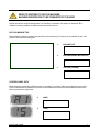
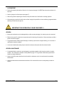
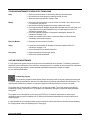
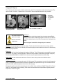
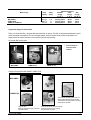
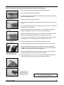
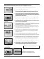
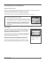
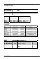
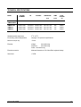
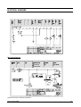
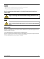
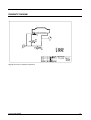
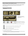
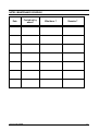
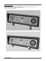
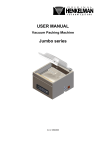
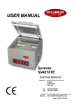
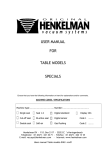
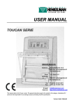
07/2013
Mod: GA-80/N
Production code: MINI JUMBO
USER MANUAL
Version 06.03 JUM.EN
CONTENT USER MANUAL
INTRODUCTION / LIABILITY /
GUARANTEE
…….……………………………………………………………..
2
CONTENT USER MANUAL
……….…………………………………………………………..
3
MACHINE REGISTRATIE
……….…………………………………………………………..
4
IMPORTANT FOR INSTALLATION – READ THIS FIRST !!!! ..……………………………………………..
5
IMPORTANT FOR INSTALLATION – READ THIS FIRST !!!! ………………………………………………
6
WARNING LABELS
……….…………………………………………………………..
7
IMPORTANT MACHINE PARTS
……….…………………………………………………………..
8
……….…………………………………………………………..
9
START UP AND OPERATION
ON/OFF switch
Start the machine
Standard user operations
OPERATING PANEL
……….…………………………………………………………..
Control panel version
Control panel layout
Control panel use
MACHINE MAINTENANCE
ELECTRICAL DIAGRAMS
11
11
11
12
……….…………………………………………………………..
General
Important before and during maintenance
Standard maintenance schedule
Vacuum pump maintenance
Seal system maintenance
Silicone holder and lid gasket maintenance
List of maintenance parts
TECHNICAL SPECIFICATIONS
9
9
10
14
14
14
15
15
18
21
22
……….…………………………………………………………..
23
……….…………………………………………………………..
24
Error code
25
PNEUMATIC DIAGRAMS
……….…………………………………………………………..
26
PROBLEM SOLVING
……….…………………………………………………………..
27
……….…………………………………………………………..
29
SPECIAL APPLICATIONS
Packaging liquid products
External vacuuming of food containers
29
30
MAINTENANCE SCHEDULE / NOTES
……….…………………………………………………………..
31
REMOVAL FRONT PANEL
……….…………………………………………………………..
32
Version 06.03 JUM.EN
3
PRIOR TO STARTING TO USE THE MACHINE,
MACHINE REGISTRATION TO BE COMPLETED BY THE USER
Register the machine using the following data. This information is necessary if the supplier or Henkelman BV is
contacted concerning questions or references about the specific machine.
DATA ON MACHINE TAG
Relevant data for answering questions can be found on the machine tag. The machine tag is located at the rear of the
machine. Note down the following data:
1.
MACHINE TYPE
2.
MACHINE NUMBER (MACHINE NO.)
3.
VOLTAGE (TENSION)
CONTROL PANEL DATA
When starting the machine two codes first appear on the display in succession before control switches to user mode.
The first code indicates the software version of the control software and the second code indicates the options active.
Write both codes in the space below:
Version 06.03 JUM.EN
4.
CODE 1
5.
CODE 2
4
IMPORTANT FOR INSTALLATION !!! READ THIS FIRST !!!
GENERAL
First read this manual carefully before the machine is put into operation. This manual contains relevant information
and instructions for starting up, maintenance and applications. If problems arise with the machine that could have
been avoided by referring to this manual then the guarantee expires.
Henkelman BV wishes the customer lots of pleasure for an extended period from the purchase of the machine. If
there are any problems or questions then the customer can always approach the supplier or Henkelman BV.
ENVIRONMENT
The machine must be moved or transported in an upright position. The machine may NOT be tilted as this can cause
damage to the pump.
Place the machine on a flat, level floor. This is essential for problem free operation of the machine.
Enough space must be left around the machine for good ventilation. The space must be at least 5 centimetres.
The ambient temperature in which the machine is operated must be between 5 0C and 30 0C. When operating the
machine in other ambient temperatures the user must contact the supplier for advice.
NEVER place the machine directly next to a heat source or a steaming device (for example a combo-steamer,
dishwasher or stove)
POWER / EARTH
Check that the voltage stated on the machine tag is the same as the mains voltage.
Always connect the machine correctly to an earthed socket to avoid danger for fire or electrical shocks (earth
connection is green/yellow).
The power cable must always be free and nothing may be placed on it.
Replace the power cable immediately if damaged.
Always disconnect the power if there are problems with the machine or during maintenance, prior to starting work on
the machine.
If the machine is stationary for long periods then the power should always be disconnected..
Version 06.03 JUM.EN
5
VACUUM PUMP
Check before starting the machine if there is oil in the pump (see page 16). NEVER start the machine without oil in
the pump.
Use the right type of oil for the pump (see page 17).
After moving and/or transporting the machine, always first check the oil level before re-starting operation.
When starting the machine for the first time or after a lengthy idle period first run the conditioning programme before
operating the machine (see page 15).
IMPORTANT FOR OPERATION !!! READ THIS FIRST !!!
GENERAL
Never pack products that can be damaged during or after vacuum packaging. Live oats may never be vacuumed.
Refer to this manual if in doubt as to the operation and/or functioning of the machine. If the manual does not offer a
solution consult the supplier.
The guarantee and/or liability expires if damage is caused by repairs and/or changes made by you. In the case of
malfunctions contact the supplier.
In the case of malfunctions always stop the machine and remove the power cable from the wall socket.
GENERAL MAINTENANCE
It is essential that the machine is serviced regularly to guarantee operation and to keep the machine in optimal
condition. The maintenance schedule is clearly defined on page 15. The guarantee automatically expires due to
overdue or sloppy maintenance.
Always remove the power cable from the wall socket for maintenance work, the machine must be completely
disconnected.
If there are doubts about the maintenance activities or if the machine fails to work correctly always contact the
supplier.
Version 06.03 JUM.EN
6
TRANSPARENT LID
Never locate the machine near a heat source. This can cause damage to the lid (cracks).
Never place hot, sharp, or heavy objects on the lid. These can cause damage to the cover (cracks) in the long run.
Always clean the cover with solvent-free cleaning agents. Solvents can damage the lid.
Check at least once a week if there are cracks in the lid. If cracks are visible in the lid then the machine must
IMMEDIATELY be turned off and not used again until the lid has been replaced. Continuing to work with a cracked lid
can cause the lid to implode. All guarantees and/or liability expire in the case of accidents and/or damage caused by
working with a cracked lid.
Replace the transparent cover every 4 years as a precautionary measure as a standard maintenance interval.
VACUUM PUMP
Regularly check the level and quality of the oil in the pump. If too little oil or the quality of the oil is bad (turbid),
replace or top up the oil before operating the machine (see page 16). Let the pump conditioning program run at least
one full cycle before replacing the oil (see page 15).
Use the right type of oil for the pump when replacing or topping up (see page 17).
Use the conditioning program at least once a week to enhance correct and long-lasting pump operation (see page
15).
WARNING SIGNS ON THE MACHINE !!!
ONLY use the prescribed power supply voltage.
Insert the plug firmly into the mains wall socket.
Always connect the machine to an earthed wall socket.
Always remove the plug during maintenance or when the machine is not in use for extended periods.
Version 06.03 JUM.EN
7
IMPORTANT MACHINE PARTS
2
3
1
4
5
Vacuum chamber
1
10
8
11
9
7
6
Side view JUMBO 35 / 42
10
14
15
10
11
11
9
9
13
Rear view MINI JUMBO /
JUMBO PLUS
Rear view MINI JUMBO / JUMBO PLUS
underneath left (cover removed)
14
1.
2.
3.
4.
5.
6.
7.
8.
9.
10.
11.
12.
13.
14.
15.
Sealing bar in vacuum chamber mounted sealing supports with a click system
or screws
Silicone holder mounted on transparent lid
Lid gasket in lid for hermetic seal
Gas springs for opening lid after machine cycle (MINI JUMBO / JUMBO
PLUS 1 gas spring in the middle)
Vacuum / Ventilation opening
Control panel
Vacuum pressure meter
ON/OFF Switch
Oil drain plug
Oil fill plug
Oil inspection window
Power cable
Fuse holder with fuses
Machine tag
Warning stickers
15
13
Rear view JUMBO 35 / 42
13
12
Appearance of parts and machines can deviate per model from illustrations
Fuse holder / Power cable
Version 06.03 JUM.EN
8
STARTING AND OPERATING THE MACHINE
ON/OFF SWITCH
The ON/OFF switch is used to turn the machine on and off before and after operation.
CAUTION – The ON/OFF switch does not completely remove all power from the machine. The power cable must be
unplugged from the wall socket to remove all power from the machine. Ensure that the machine is completely without
power during maintenance and repair activities is.
When the machine is turned on (with the ON/OFF switch), then the pump only runs during the vacuum cycle.
START MACHINE
When the machine is connected, then the machine can be turned on using the ON/OFF switch. When starting the
machine two codes first appear in succession on the display before control switches to user mode.
The first code indicates the control software version. The second code indicates the machines
active options. Note both codes on page 4 of this manual as they are important for the supplier or
Henkelman BV when making enquiries and/or if any problems arise.
After switching to user mode the machine is ready for use. If the machine is new or has not been
used for an extended period, then it is important to run the conditioning program for the pump (15
minutes) to maintain the pump. For instructions on the conditioning programme, see page 15.
After switching to the user mode the display could read [ OIL ]. This means that the operating hours
counter is turned on and the set number of operating hours has elapsed. The hour counter is
turned off by default but the client supplier can use it as a reminder for regular maintenance
activities.
When [Oil] is displayed the machine can be still be used as usual but it is advisable to either turn off
the hour counter or to reset it.
Contact the supplier for more information about setting or turning off the
operating hours counter.
Version 06.03 JUM.EN
9
STANDARD USER OPERATIONS FOR THE MACHINE
1.
Turn the machine on with the ON/OFF switch. Warm the pump up with the condition programme if the machine has
stood idle for some time (instructions page 15).
2.
Fill the vacuum bag with product. Select the correct format bag that easily fits around the product but is not too
large for the product. Ensure hygienic conditions during this operation. Packaging materials, product and hands
must be clean and if possible dry.
3.
Lay the vacuum bag in the chamber. The open side must be laid over the sealing bar. The bag may however not
extrude from the chamber. If the product is a lot lower than the height of the sealing bar then insertplates that are
supplied standard with the machine can be used. This makes the operation easier and reduces the cycle time.
4.
The vacuum bag must be placed over the sealing bar without any folds.
5.
Multiple vacuum bags can be placed over the sealing bar if the sealing bar is longer than the opening of the
vacuum bag. Vacuum bags may not however be laid on top of each other on the bar.
6.
Set the correct value for vacuum and sealing functions. See page 13 for setting the function values.
7.
Close the lid and the machine automatically runs through the full cycle of installed functions. The lid opens
automatically when the last function “ventilation” has finished.
8.
If necessary the cycle can be fully or partially interrupted by pressing the [VACUUM STOP] key or the [STOP] key.
The [VACUUM STOP] key interrupts the active function (vacuum or sealing) and automatically continues with the
next function.
The [STOP] key interrupts the entire cycle and goes immediately to the ventilation function.
9.
The packed product can be removed from the machine.
SAFETY and PRODUCT PROTECTION
The packing process can be partially or fully interrupted at all times:
Stop active function, press on [VACUUM STOP] key
Stop full machine cycle, press [STOP] key
OPTIMAL AND EFFICIENT PACKAGING RESULT
Use the correct format and good quality vacuum bags
Maximum 75% product filling in vacuum bag
Place vacuum bag fold free over seal beam (use correct number in inlay plates in chamber)
Version 06.03 JUM.EN
10
CONTROL PANEL
CONTROL PANEL VERSION
Digitale time control
The digital control is implemented with a function program that can be set with different
function values per cycle (to be able to pack different products). A program cycle is the
complete program of set functions (vacuum and seal) that the machine runs through to
package a product.
The control panel is implemented standard with a conditioning program for the regular
maintenance of the pump and two STOP keys for complete function interruption or for only
active function interruption. There are also a number of built-in service programs. Contact the
supplier or Henkelman BV for more information about these functions.
The value of the functions can be set for a certain time period.
The vacuum function can be set to whole seconds with a maximum of 99 seconds.
The seal function can be set with an interval of 0.1 seconds and a maximum of 6.0 seconds.
CONTROL PANEL LAYOUT
2
1
5
0,6
0,4
0,8
8
3
VACUUM
4
SEAL
4
6
0,2
-1
7
0
1. Display
Displays the status of the active function during the run of the program cycle or the set value of the selected function
when machine is not running.
2. FUNCTION SELECTION Key
Select function (vacuum or seal) for viewing or changing function values. The function is selected if the function light is
on in front of the function description under the display.
3. CONDITIONING PROGRAMME Key
Start the conditioning program for pump (duration 15 minutes). For instructions on the program, see page 15.
4. FUNCTION Lights
A light in front of the function indicates that the function is active during the program cycle or that the function is selected
for view or change.
Version 06.03 JUM.EN
11
5. + / STOP VACUUM Key
Function during cycle
General function.
6. - / STOP Key
Function during cycle
General function
Interruption of the active function during the program cycle. The cycle immediately
continues with the next function.
Increment the value of the selected function.
Terminates the program cycle completely. The cycle immediately switches into the
ventilation function.
Decrement the value of the selected function.
7. Vacuum meter
Displays the pressure in the vacuum chamber.
8. ON/OFF Switch
The ON/OFF switch is used to turn the machine on and off before and after operation. The switch turns on all units in the
machine. Caution, the switch does not completely remove all power from the machine.
CONTROL PANEL USE
When the machine is turned on it is ready for use once the two operating codes have displayed.
Description of the program cycle for digital time control
1. Functions (vacuum and sealing) are set with the correct values (see page 13 for settings)
2. Close the lid.
3. Vacuum function
The machine starts to vacuum the chamber.
The light in front of [VACUUM] goes on.
Display : decrementing time per second starting at the time set (max. 99 sec.).
Vacuum meter starts increasing to the left.
4. Sealing function
Once the vacuum function is finished, the sealing function starts to seal the vacuum bag(s).
The light in front of [SEAL] goes on.
Display : decrementing time per 0.1 second starting at the time set (max. 6.0 sec.).
The reading on the vacuum meter stays the same.
5. Ventilating function
After ending the seal function the ventilating function starts ventilating the chamber to 1
atmosphere/ATO and the lid opens.
There are no longer any lights on in front of the functions.
Display : lines moving up and down until the lid is opened.
The vacuum meter runs back to the right to zero and the lid opens automatically.
6. The product is packed and ready to remove.
Version 06.03 JUM.EN
12
Set/change function values
The following steps must be followed to change the function values for vacuum and/or seal :
Press the FUNCTION SELECT Key to select the required function. The function light will light up when the function is
selected.
Press the [+ / STOP VACUUM] or [- / STOP] keys for incrementing or decrementing the function values respectively. It
takes 0.5 seconds before the value begins to change.
After changing the value(s) the machine must run through the cycle once (see previous page) to record the values.
Vacuum function
The vacuum function value can be incremented or decremented per second with a maximum of 99 seconds and a
minimum of 2 seconds.
If while changing the vacuum function setting the [+ / STOP VACUUM] or [- / STOP] key is held down then the first 5
seconds will be incremented or decremented per second. Then intervals of 10 seconds will appear. If the key is released
then the settings can be changed again per second.
Sealing function
The seal function setting can be increased or decreased with a maximum of 6.0 sec. and a minimum of 0.5 sec.
If while changing the seal function setting the [+ / STOP VACUUM] or [- / STOP] key is held down then the first 0.5
seconds will be incremented or decremented per 0.1 second. Then intervals of 1.0 second will appear. If the key is
released then the settings can be changed again per 0.1 second.
Service programs control panel
The control panel is also equipped with a number of service programs that can be useful during regular maintenance or
repairs. The conditioning program for the pump is the most used service program (see explanation on page 15).
Contact the supplier for more information about the use of other service programs.
Version 06.03 JUM.EN
13
MACHINE MAINTENANCE
GENERAL
Regular, thorough maintenance is essential for extending the machine's life, for preventing malfunctions and for
achieving an optimal packaging result. If the machine is used intensively (more than 5 hours per day) then it is a
professional service is recommended every 6 months. In other cases one complete service per year is sufficient
(depending on location, environment and products).
There are however also small maintenance activities that must be carried out more regularly and that the user can do
himself. The following page contains an overview of these activities.
IMPORTANT BEFORE AND DURING MAINTENANCE
The machine must always be completely voltage free before any maintenance is carried out on it. Always remove the
plug from the wall socket.
If the machine is not functioning properly or if it produces strange noises, turn it off immediately with the ON/OFF
switch and contact the supplier.
When cleaning transparent lids NEVER use cleaning agents containing solvents. Check at least once a week if there
are cracks in the lid. In case of cracks, turn off the machine immediately and contact the supplier.
High pressure cleaning is not permitted for cleaning the machine. High pressure cleaning can cause considerable
damage to electronic and other parts of the machine.
Water may never be permitted to enter either the extraction nozzle of the chamber or the blow-off hole of the pump.
This would cause irreparable damage to the pump.
Larger services must always be carried out by an authorised supplier.
The JUMBO machines are designed for a maximum of 5 hours per day. The supplier cannot be
held responsible for any malfunctions or defects if these operating limits are clearly exceeded without consultation.
The machine must be moved or transported in an upright position. The machine may NOT be tilted as this can cause
damage to the pump.
The supplier cannot be held responsible for any malfunctions or defects if the maintenance
instructions in this manual are not followed.
Version 06.03 JUM.EN
14
STANDARD MAINTENANCE SCHEDULE FOR THE MACHINE
Daily
Clean the vacuum chamber, lid and housing after use with a damp cloth.
Be careful that no cleaning agents containing solvents are used.
Make sure that no high pressure cleaner is used.
Weekly
Check the oil level and replace or top up oil if the oil is turbid or the oil level is too low.
For instructions, see page 16.
Activate the conditioning program for the pump at least once a week.
Check the seal beam for damage. Replace teflon tape/seal wire if the seal quality is no
longer sufficient or if the teflon tape/seal wire is no longer taught on the bar. For
instructions, see page 18-19.
Check the lid gasket and replace it if the gasket is damaged or stretched. For
instructions, see page 17-18.
Inspect the transparent lid for cracks. If cracks are visible, turn off the machine
immediately and contact the supplier.
Every Six Months
Replace oil at least once every 6 months.
Yearly
Inspect the oil exhaust filter for saturation. If saturated, replace the filter. For
instructions, see page 17-18.
Contact the supplier for a professional service
Four-yearly
Replace transparent lid and the gas springs
Replace seal cylinder membranes.
VACUUM PUMP MAINTENANCE
It is very important to regularly service the pump to ensure extended and correct operation. The following activities are
essential for correct maintenance. If the machine is used regularly then it is advisable to have the pump fully inspected at
least once a year by the supplier to ensure extended and problem free operation. Contact the supplier
for more advice and information.
Conditioning program
The conditioning program ensures that the pump is thoroughly rinsed. During the programme the pump and
oil reaches operating temperature so that the oil can better absorb any moisture and contaminants and filter them. The
high temperature enables any moisture in the pump to evaporate minimising the risk for corrosion in the pump.
The program lasts 15 minutes and it is advisable to run it at least once a week. Turn on the machine, press the key
[conditioning program], and close the lid. The program runs automatically. During the program the display will display
moving dots.
The program can be interrupted at any time using the [STOP] key. It is however important for the sake of good
maintenance that the program completes a full 15 minute cycle and therefore advisable only to interrupt the cycle for
something urgent.
It is also advisable to run the program before using the machine for the first time, after the machine has been stationary
for a lengthy period of time, and especially prior to changing oil.
Version 06.03 JUM.EN
15
Changing Oil / Filling Up
The oil level and oil quality must be checked at least once a week. The oil inspection window serves this purpose. Top
up the oil level if it is too low. Replace the oil if it is turbid. Oil must be replaced at least once every 6 months.
1
1
1
3
3
3
1. Oil fill plug
2. Oil drain plug
3. Oil inspection
window
2
2
2
Rear view MINI JUMBO
after opening rear end.
Rear view JUMBO PLUS
after opening rear end.
Take care to use the correct
type of oil for the pump
Beware of hot oil fumes
during drainage
Side view JUMBO 35 / JUMBO 42
Draining oil
If the oil is white or turbid when checked then it must be replaced. Before
draining off the oil let the conditioning program run a full cycle. The dirt and
moisture is absorbed by the oil and the oil becomes thinner making draining
easier.
After the program has ended the drainage plug can be removed.
CAUTION, when unscrewing hot oil fumes can escape. The oil now drains from the drain hole (an oil pan must be
placed underneath). When the oil has drained, tilt the machine slightly so that all residual oil can drain off. After draining
the oil drain plug is replaced.
Filling up oil
After draining or if the oil level has dropped, oil needs to be filled up. The oil fill plug must be removed with the correct
size spanner. The pump can now be filled with oil. Make sure that you add the correct amount (see table on page 24)
For the models MINI JUMBO and JUMBO PLUS, slide the component plate backwards to facilitate filling.
TAKE CARE to fill with small amounts at intervals. Fill the oil level to the top of the oil level indicator sticker.
Oil types and amounts
It is important to use the correct type and quantity of oil for the pump. The wrong type or too much oil could damage the
pump. The ambient temperature where the machine is operated is also important for the type of oil. See amounts and
types with related ambient temperatures in the table on the next page.
Examples of supplier brands for the standard types of oil are Shell Vitrea, Aral Motanol GM, BP Energol CS, or Texaco
Regal R+ O with related viscosity numbering. If the machine is used outside normal specifications regarding ambient
temperature, contact the supplier.
Version 06.03 JUM.EN
16
Machine Type
MINI JUMBO
JUMBO PLUS
JUMBO 35 / JUMBO 42
Machines are supplied with standard type oil.
Pump
Capacity
Filling
(litres)
004 m3/h
008 m3/h
016 m3/h
0.05
0.2
0.3
Ambient temperature
Standard
“Cold”
“Hot”
Oil type
Oil type
Oil type
10 - 30 oC
5 - 10 oC 30 - 40 oC
Viscosity VG 22
Viscosity VG 32
Viscosity VG 32
VM 22
VM 32
VM 32
VS 22
VS 32
VS 32
Inspect and change oil exhaust filter
There is an oil exhaust filter in the pump that absorb and filter oil vapours. The filter will become saturated after a period
of time and needs to be replaced. This is on average between 9 and 18 months. When the filter is saturated it is no
longer possible to achieve maximum vacuum and the machine starts smoking.
Oil exhaust filter housing types
Filter housings are
at the rear of the
machine.
MINI JUMBO
JUMBO PLUS
JUMBO 35 / 42
Change oil exhaust filter MINI JUMBO / JUMBO PLUS
MINI JUMBO
JUMBO PLUS
Take care that the filter gasket does not
remain behind when removing the filter.
Take care that the filter gasket is correctly
placed on the new filter.
Open the back
Slide the component board to the back
Unscrew the filter
Version 06.03 JUM.EN
Remove the old filter from the housing
Place the new filter in the housing.
Screw the filter on again
17
Change oil exhaust filter JUMBO 35 / JUMBO 42
Open the rear of machine
for the pump
Unscrew the cover
from the filter housing
The filter is visible clamped
behind a tensioner
Release the tensioner with
a spanner
Position and clamp the new filter (ensure that the
seal ring is in position) in the housing.
Screw the cover back onto the housing.
Screw the back plate back onto the machine.
Remove tensioner and
filter from the housing
•
•
•
Ensure that the sealing ring does not
remain behind when removing the filter
Pumps and housing can have a different appearance but the principle of replacing them remains the same.
Take care that the correct type of filter is used for the pump type, see page 29 for correct type of filter for the type of pump.
It is advisable to have the suppler do this service.
SEAL SYSTEM MAINTENANCE
The seal system for the JUMBO series is a single 3.5 mm convex sealing wire.
SINGLE SEAL
1 x 3,5 mm seal
The seal quality is partially dependent on the maintenance of the sealing bar and silicone holder.
The main maintenance activities are the daily cleaning of the sealing bar and silicone holder with a
damp cloth and a weekly inspection of the bars with replacement of the sealing wire, teflon tape or
silicone rubber if irregularities appear on top of the bar or the seal quality is insufficient.
The models MINI JUMBO and JUMBO PLUS are equipped with a hard-tissue sealing bar with
clamps on both sides of the sealing beam. The sealing bar is attached to the holders with screws.
The models JUMBO 35 and JUMBO 42 are equipped with an anodised
aluminium sealing bar with clamps on the bottom of the sealing bar. The sealing
bar is clicked to the holders.
DOUBlE SEAL
2 x 3,5 mm seal
CUT_OFF-SEAL
1 x 3,5 mm seal
1 x 1,1 mm cut
The steps for replacing the sealing wire and teflon tape are described on the
following pages. The appearance may differ but the procedure remains the
same.
The average maintenance cycle of the sealing bar (teflon tape / sealing wire) is at least once every 3 months.
(This indication refers to regular use of the machine and packaging standard products with standard vacuum packaging materials. No rights can be
derived from this indication)
Version 06.03 JUM.EN
18
Replace sealing wire and teflon tape on Mini Jumbo and Jumbo Plus (only single seal)
Remove teflon tape
Unscrew and remove
sealing wire
Screw sealing wire down
under a clamp plate.
1.
Remove the sealing bar from the holders by unscrewing the screws
2.
Remove the teflon tape from the sealing bar.
3.
The old sealing wire can be removed by unscrewing the clamp bands and pulling the
wires from the plate or groove.
4.
Degrease the sealing bar with a clean cloth.
5.
Cut a new piece of sealing wire to the length of the sealing bar plus about 15 cm (± 6
inches).
6.
Push one end of the wire through the clamp plate or grooves on the side or bottom of
the sealing bar and screw down.
7.
Clamp the sealing bar with the top facing down in a vice and pull the sealing wire
through the clamp plate or groove on the other side of the sealing bar.
8.
Pull the wire taught with a pair of pliers and screw it down at the same time. Ensure
that the wire is pulled tight and straight prior to screwing down the wires.
9.
It is handy to use a pair of pliers as a lever for optimal wire tension. Grip the end of
the sealing bar in a vice and tension the wire by pressing the bar down.
10. Cut the protruding wire ends off on both sides directly past the screws.
11. Cut a piece of teflon tape as long as the sealing bar plus about 5 cm (± 2 inches).
12. Stick new teflon tape straight over the new sealing wire. Ensure that the teflon is
straight on the sealing bar and that the sticky part is stuck on the side. Ensure that
the teflon is stuck on the bar smoothly and without folds.
Pull the wire tight in
second clamp plate using
a pair of pliers and a vice.
13. Cut the teflon tape off so that the sticky part does not get stuck on the sides of the
clamps but that the teflon extends over the top of the clamps.
14. Place the sealing bar back in the machine. Ensure that the sealing bar is properly
clicked onto the holders or that the screws are hand-tight screwed in.
Cut off the ends of the
sealing wire and stick
teflon tape tightly on the
beam without folds.
Version 06.03 JUM.EN
See page 22
for correct parts and quantities
19
Replace sealing wire and teflon tape Jumbo 35 and Jumbo 42 (double and cut-off seal)
1. Remove the sealing bar from the holder by releasing the click system.
2. Remove the teflon tape from the sealing bar.
3. The old sealing wires and cut-off wires (if applicable) can be removed by
unscrewing the clamp (see illustration) and pulling the wires from the grooves.
Remove teflon tape
4. Remove the teflon tape that is attached to the top of the sealing bar and stick a
new piece of teflon tape to the bar of the same length after having degreased and
cleaned the bar with a dust free cloth.
5. Cut a new peace of sealing wire or cut-off wire to the size of the sealing beam
plus about 15 cm (± 6 inches). If 2 sealing wires or an extra cut-off wire is on the
sealing beam then a second sealing wire or cut-off wire must of course be cut.
Unscrew and remove
sealing wires
6. Place the end of the wire or wires through the groove(s) on the side of the sealing
beam and screw the wires to the bottom.
7. Place the sealing bar top down in a vice and pull the sealing wire or wires through
the other side of the groove(s) on the sealing beam.
8. Pull the wires tight with a pair of pliers and screw them down at the same time.
Ensure that the wire (wires) is (are) pulled taught and straight with the help of a
pair of pliers before the wires are screwed down.
Replace the teflon tape
9. It is handy to use a pair of adjustable pliers as a lever for optimal wire tension.
Place one end of the sealing beam in the vice and stretch the wire (wires) by
pressing down the bar.
10. Cut off the extruding wire end(s) on both ends after having screwed it tight.
11. Cut a piece of teflon tape as long as the sealing bar plus about 5 cm (± 2 inches).
Screw down new wires
onto clamping plate
12. Stick the new teflon tape straight over the new sealing wire (wires). Ensure that
the teflon is straight on the sealing bar and that the sticky part is stuck on the
side. Ensure that the teflon is stuck on the bar smoothly and without folds.
13. Cut the teflon tape off so that the sticky part does not get stuck on the sides of the
clamps but that the teflon extends over the top of the clamps.
14. Place the sealing bar back in the machine. Ensure that the sealing beam is
properly clicked onto the holders or that the screws are firmly screwed in.
Pull wires taught using a
pair of pliers and a vice
and screw the wires down
on the clamping plate.
See page 22
for correct parts and quantities
Cut off the ends of the sealing wire and stick
Teflon tape over the sealing beam without folds
Version 06.03 JUM.EN
20
SILICONE HOLDER AND LID GASKET MAINTENANCE
Replace the rubber silicone holder
The silicone holder must be inspected weekly for roughness on the silicone rubber (mainly caused by burning by the
sealing wire). If irregularities appear then the silicone rubber must be replaced.
Average maintenance cycle for silicone rubber is at least once every 6 months
(This indication refers to regular use of the machine with standard products. No rights can be derived from this indication)
1. Remove the old silicone rubber from the holder.
2. Cut a new piece of silicone rubber the same size as the old one. The same
size is very important, too short or too long will cause problems with sealing.
3. Place the new piece in the silicone holder. Ensure that the silicone rubber is
completely and evenly placed in the groove. It is also important that the
surface of the silicone rubber is smooth after it is in place and is shows no
signs of tension.
Appearance may differ per model
but principle remains the same.
Replace lid gasket
The lid gasket ensures that the vacuum chamber is completely sealed during the
machine cycle. This is essential to achieve a maximum vacuum. The lid gasket
wears due to the extreme pressure differences and must be replaced regularly.
Inspect the lid rubber weekly for tears or damage.
Average maintenance cycle for silicone rubber is at least once every 6 months
(this indication refers to regular use of the machine, on average 5 hours a day and with standard
products. No rights can be derived from this indication)
The length of the new lid gasket is measured against the old rubber. If the lid
gasket is too short or too long it can cause problems closing the lid or leak.
The gasket must be placed evenly and without tension in the holder. The ends
must be cut straight and must be laid tightly against each other to avoid leakage.
Version 06.03 JUM.EN
Ensure that the ends of the lid
gasket line up accurately
Lid rubbers can vary per model,
see page 21
21
LIST OF SERVICE PARTS
VACUUM PUMP PARTS
BUSCH VACUUM PUMPS
HENKELMAN MODELS
004m3/h
008 m3/h
016 m3/h
MINI JUMBO
JUMBO PLUS
JUMBO 35 / 42
BUSCH
STANDARD OIL
Henkelman
Type
Litres
Reference
004 m3/h
008 m3/h
016 m3/h
VG 22
VG 32
VG 32
0439501
0439510
0439510
0.05
0.20
0.30
OIL EXHAUST FILTER
Henkelman
amount
Type
Reference
50-60Hz
50-60Hz
50-60Hz
0939000
0939001
0939003
1
1
1
SEAL SYSTEMS
PARTS
SPECIFICATIONS
HENKELMAN
REFERENCE
QUANTITY
Teflon tape
46 mm teflon tape
0305515
length sealing bar + 5 cm
Single seal
1 x 3.5 mm round wire
0305000
1 wire length of sealing bar + 15 cm
Double seal
2 x 3.5 mm round wire
0305000
1 wire length of sealing bar + 15 cm
Cut-off seal
1 x 3.5 mm round wire
1 x 1.1 mm round wire
Silicone 17 x 8
0305000
0305010
0320200
1 wire length of sealing bar + 15 cm
1 wire length of sealing bar + 15 cm
length silicone holder
Mini Jumbo, Jumbo Plus
Jumbo 35 ,Jumbo 42
Jumbo 35 ,Jumbo 42
Silicone Rubber
LID GASKET
MODELS
HENKELMAN
LENGTHS PER MODEL (in cm)
REFERENCE
MINI JUMBO / JUMBO PLUS
0320100
MINI JUMBO / JUMBO PLUS
140
JUMBO 35 / 42
0320215
JUMBO 35
JUMBO 42
175
190
Lengths specified are always a little longer and must be cut to the correct length.
Version 06.03 JUM.EN
22
TECHNICAL SPECIFICATIONS
MODEL
JUMBO SERIES
MINI JUMBO
JUMBO PLUS
JUMBO 35
JUMBO 42
VACUUM
CHAMBER
LID
HOUSING
Stainless-steel
Stainless-steel
Stainless-steel
Stainless-steel
Transparent
Transparent
Transparent
Transparent
Stainless-steel
Stainless-steel
Stainless-steel
Stainless-steel
DIMENSIONS
PUMP
(mm)
(m3/h)
FINAL
VACUUM
(%)
330 x 450 x 295
330 x 450 x 295
450 x 525 x 385
490 x 525 x 430
004
008
016
016
99,80%
99,80%
99,80%
99,80%
Specifications may deviate with optional models
Standard ambient temperature
For deviating ambient temperatures
5 0C – 30 0C
see page 17 for special oil specifications
Maximum use per day
5 hours
Electricity
Voltage :
see machine tag
Frequency :
see machine tag
Power : see machine tag
Electrical connection
Maximum fluctuation ± 10% of the official registered voltage
Sound level
< 70 DB
Version 06.03 JUM.EN
23
ELECTRICAL DIAGRAMS
Control Current Diagram
Main Current Diagram
Diagrams are shown for standard configurations.
Version 06.03 JUM.EN
24
List of fuses
Fuses have been placed where the power comes onto the component board
Fuses have been placed on transformers (control and seal)
Two fuses have been placed on the control circuit.
Due to different mains voltages and machine models there is a variety of fuse types that can be present in the machine.
Refer to the specifications of the relevant component for the correct types and values of fuses for replacement, or
contact the supplier.
Caution, to avoid fire and/or other irreparable damage to the machine, replacement fuses must
always be of the same type with the same value as the fuses being replaced !!
Spanning
Caution, the maximum allowable voltage fluctuation is ± 10% of the official voltage stated on the
type tag.
ERROR CODES
The control is programmed with an error code. This error code indicates there is a problem with the proper function of
the lid switch of there is a user fault.
F1: This code indicates that the cycle (lid switch) will be interrupted prematurely.
Example: the cover of the machine closes after starting, but before sufficient vacuum is present to keep the cover closed
the operator lets go of the cover. The F1 code will now be shown on the display.
If this keeps happening please contact the supplier or your dealer
Version 06.03 JUM.EN
25
PNEUMATIC DIAGRAM
Diagrams are shown for standard configurations.
Version 06.03 JUM.EN
26
PROBLEM SOLVING
SOLUTION
CAUSE
PROBLEM
Machine does not work •
•
•
•
Machine does not work •
Operating panel is on
•
The plug is not plugged into the wall
socket.
The main fuse is burnt.
•
Plug the plug into the wall socket.
•
Replace the fuse (Ensure the correct
value).
Check this and if necessary re-fasten it.
The ON/OFF switch’s contact block has •
come loose.
The circuit board fuse is burnt.
•
The control transformer fuse is burnt.
•
Disassemble the front panel and replace
the fuse.
Check this and if necessary replace it.
•
The micro-switch that is activated when •
the lid is closed is disordered or faulty.
•
There is an internal malfunction.
Transparent lid does
not open automatically
•
The gas spring is faulty
•
Consult the supplier.
Final vacuum is
insufficient
•
•
The set vacuum time is too short.
There is too little oil in the vacuum
pump.
The extraction hole at the back of the
vacuum chamber is partially covered by
the vacuum bag during extraction
The lid gasket is worn.
The oil is contaminated
The oil exhaust filter is saturated.
•
•
Extend the vacuum time.
Check the oil level and top up if
necessary (Note the type and quantity).
Place the vacuum bag closer to the
sealing beam.
•
•
•
•
•
•
•
•
The micro-switch must be properly
adjusted or replaced
Consult the supplier.
Replace the lid gasket.
Replace the oil (Note the type & amount).
Replace the oil exhaust filter / Consult
the supplier.
.
The machine builds up
a vacuum slowly
Version 06.03 JUM.EN
•
•
The pump’s extraction filter is blocked.
The oil exhaust filter is saturated.
•
•
Consult the supplier.
Replace the oil exhaust filter / Consult
the supplier.
27
The vacuum bag is
not properly and/or
correctly sealed.
SOLUTION
CAUSE
PROBLEM
•
The vacuum bag is being placed
incorrect on the sealing bar.
•
•
•
The sealing time is too long or too short.
The silicone rubber in the silicone holder
is damaged or worn.
The teflon tape is damaged.
The inside of the vacuum bag opening is
contaminated or greased.
•
•
Place the vacuum bag neatly and
smoothly on the sealing bar. Ensure that
the opening of the bag is always within
the vacuum chamber.
Adjust the sealing time longer or shorter.
Replace the silicone rubber.
•
•
Replace the Teflon tape
Clean the vacuum bag’s opening.
•
•
In the case of other problems or questions contact the supplier or Henkelman BV.
Version 06.03 JUM.EN
28
REMARKS ON SPECIAL APPLICATIONS
PACKAGING LIQUID PRODUCTS
The machines can be also used for packaging liquid products like soups or sauces. During this process the vacuum
process must be carefully monitored through the lid. The [STOP VACUUM] key must be pressed as soon as bubbles
appear in the product; the saturation point (same as boiling point) has then been reached.
The saturation point of liquids is reached at a certain ratio of low pressures and high temperatures (see the example
table for water below). The saturation point will be reached sooner in the vacuum process when packaging liquids with a
high temperature (the amount of vacuum will therefore be less).
Henkelman recommends therefore to first cool liquid products before packaging. By so doing an optimal vacuum can be
achieved for the product.
Saturation point of water – relation between the pressure and temperature of the water
Vacuum pressure [mbar]
1000
800
600
400
200
100
50
20
10
5
2
Boiling Point
Temperature [°C]
100
94
86
76
60
45
33
18
7
-2
-13
A handy tip when packaging liquid products is to use a liquid insertplate so that the product remains at the bottom of the
packaging during the vacuuming process and there is less risk of liquid splashing out of the packaging. Contact the
supplier or Henkelman BV for more information about the liquid insertplate.
Version 06.03 JUM.EN
29
EXTERNAL VACUUMING OF FOOD CONTAINERS (if applicable)
The JUMBO series can be equipped with an option for external vacuuming of special food containers. This system can
vacuum special dishes for longer storage life of the (food) products in the dish. The dish has a special lid with valve.
Contact the supplier for more information about the dishes. The system for the machine consists of a
hose with vacuum applicator.
Operation External Vacuum Food Containers
1. Start the machine
2. Place the hose connector over the extraction opening of the machine chamber of the machine
3. Check that the sliding valve on the
vacuum applicator is on the side of the
hose (closed position).
4. Press the conditioning key C appears in the display. Press
the SELECTOR key until [ E ] (External vacuuming) appears
on the display.
5. Place the vacuum applicator over the valve of the container and slide the sliding valve towards the lid to open the
valve.
6. Press the + Key. The vacuum pump starts to run and the container is vacuumed.
7. When the vacuum meter reaches –1 then the container is fully vacuumed.
8. Press the – Key to stop the vacuum pump
9. The vacuum applicator can now be removed from the lid by sliding back the slider.
10. The container is now ready for cool storage.
11. If the machine needs to be used for normal applications then the hose can be removed from the extraction opening
and the normal program mode can be selected by pushing twice the SELECTOR key.
Version 06.03 JUM.EN
30
NOTES / MAINTENANCE SCHEDULE
Date
Version 06.03 JUM.EN
Carried out by
whom?
What done ?
Remarks ?
31
Removal tools front panel
With every machine we ship-out we enclose two special tools to make it possible to remove the front panel.
The tools slide in the slots at the bottom side of the front panel.
Now lift it a little and pull it towards you.
Version 06.03 JUM.EN
32