1
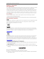
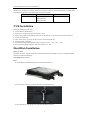
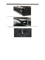
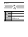
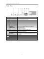
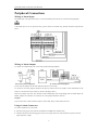
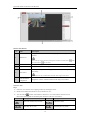
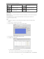
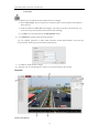
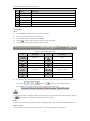
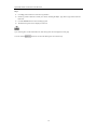
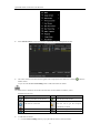
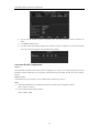
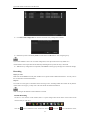
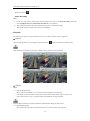
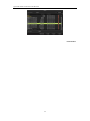
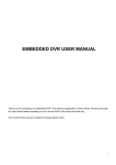
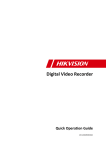
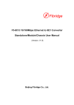
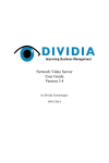
Network Video Recorder Quick Start Guide UD.6L0202B1817A01 Quick Start Guide of Network Video Recorder TABLE OF CONTENTS NVR Installation .............................................................................................................................................. 5 Hard Disk Installation ..................................................................................................................................... 5 Front Panel ....................................................................................................................................................... 7 Rear Panel ........................................................................................................................................................ 8 Peripheral Connections ................................................................................................................................... 9 Wiring of Alarm Input ................................................................................................................................ 9 Wiring of Alarm Output ............................................................................................................................. 9 Using of Alarm Connectors ........................................................................................................................ 9 Controller Connection .............................................................................................................................. 10 Specifications .................................................................................................................................................. 11 HDD Storage Calculation Chart ................................................................................................................... 12 Accessing by Web Browser ............................................................................................................................ 13 Logging In................................................................................................................................................ 13 Live View ................................................................................................................................................. 13 Recording ................................................................................................................................................. 15 Playback ................................................................................................................................................... 16 Log ....................................................................................................................................................... 17 Menu Operation ............................................................................................................................................. 19 Menu Structure......................................................................................................................................... 19 Startup and Shutdown .............................................................................................................................. 19 Changing Default Admin Password ......................................................................................................... 20 Live View ................................................................................................................................................. 20 Adding IP Cameras .................................................................................................................................. 20 One-touch RAID Configuration ............................................................................................................... 22 Recording ................................................................................................................................................. 23 Instant Recording ............................................................................................................................. 23 All-day Recording ............................................................................................................................ 24 Playback ................................................................................................................................................... 24 Backup ..................................................................................................................................................... 25 1 Quick Start Guide of Network Video Recorder User Manual©2015 Hangzhou Hikvision Digital Technology Co., Ltd. This user manual is intended for users of NVR (V3.1.4). It includes instructions on how to use the Product. The software embodied in the Product is governed by the user license agreement covering that Product. About this Manual This Manual is subject to domestic and international copyright protection. Hangzhou Hikvision Digital Technology Co., Ltd. (“Hikvision”) reserves all rights to this manual. This manual cannot be reproduced, changed, translated, or distributed, partially or wholly, by any means, without the prior written permission of Hikvision. Trademarks and other Hikvision marks are the property of Hikvision and are registered trademarks or the subject of applications for the same by Hikvision and/or its affiliates. Other trademarks mentioned in this manual are the properties of their respective owners. No right of license is given to use such trademarks without express permission. Disclaimer TO THE MAXIMUM EXTENT PERMITTED BY APPLICABLE LAW, HIKVISION MAKES NO WARRANTIES, EXPRESS OR IMPLIED, INCLUDING WITHOUT LIMITATION THE IMPLIED WARRANTIES OF MERCHANTABILITY AND FITNESS FOR A PARTICULAR PURPOSE, REGARDING THIS MANUAL. HIKVISION DOES NOT WARRANT, GUARANTEE, OR MAKE ANY REPRESENTATIONS REGARDING THE USE OF THE MANUAL, OR THE CORRECTNESS, ACCURACY, OR RELIABILITY OF INFORMATION CONTAINED HEREIN. YOUR USE OF THIS MANUAL AND ANY RELIANCE ON THIS MANUAL SHALL BE WHOLLY AT YOUR OWN RISK AND RESPONSIBILITY. TO THE MAXIMUM EXTENT PERMITTED BY APPLICABLE LAW, IN NO EVENT WILL HIKVISION, ITS DIRECTORS, OFFICERS, EMPLOYEES, OR AGENTS BE LIABLE TO YOU FOR ANY SPECIAL, CONSEQUENTIAL, INCIDENTAL, OR INDIRECT DAMAGES, INCLUDING, AMONG OTHERS, DAMAGES FOR LOSS OF BUSINESS PROFITS, BUSINESS INTERRUPTION, SECURITY BREACHES, OR LOSS OF DATA OR DOCUMENTATION, IN CONNECTION WITH THE USE OF OR RELIANCE ON THIS MANUAL, EVEN IF HIKVISION HAS BEEN ADVISED OF THE POSSIBILITY OF SUCH DAMAGES. SOME JURISDICTIONS DO NOT ALLOW THE EXCLUSION OR LIMITATION OF LIABILITY OR CERTAIN DAMAGES, SO SOME OR ALL OF THE ABOVE EXCLUSIONS OR LIMITATIONS MAY NOT APPLY TO YOU. Privacy Notice Surveillance laws vary by jurisdiction. Check all relevant laws in your jurisdiction before using this product for surveillance purposes to ensure that your use of this product conforms. Support Should you have any questions, please do not hesitate to contact your local dealer. 2 Quick Start Guide of Network Video Recorder Regulatory information FCC information FCC compliance: This equipment has been tested and found to comply with the limits for a digital device, pursuant to part 15 of the FCC Rules. These limits are designed to provide reasonable protection against harmful interference when the equipment is operated in a commercial environment. This equipment generates, uses, and can radiate radio frequency energy and, if not installed and used in accordance with the instruction manual, may cause harmful interference to radio communications. Operation of this equipment in a residential area is likely to cause harmful interference in which case the user will be required to correct the interference at his own expense. FCC conditions This device complies with part 15 of the FCC Rules. Operation is subject to the following two conditions: 1. This device may not cause harmful interference. 2. This device must accept any interference received, including interference that may cause undesired operation. EU Conformity Statement This product and - if applicable - the supplied accessories too are marked with "CE" and comply therefore with the applicable harmonized European standards listed under the Low Voltage Directive 2006/95/EC, the EMC Directive 2004/108/EC, the RoHS Directive 2011/65/EU. 2012/19/EU (WEEE directive): Products marked with this symbol cannot be disposed of as unsorted municipal waste in the European Union. For proper recycling, return this product to your local supplier upon the purchase of equivalent new equipment, or dispose of it at designated collection points. For more information see: www.recyclethis.info. 2006/66/EC (battery directive): This product contains a battery that cannot be disposed of as unsorted municipal waste in the European Union. See the product documentation for specific battery information. The battery is marked with this symbol, which may include lettering to indicate cadmium (Cd), lead (Pb), or mercury (Hg). For proper recycling, return the battery to your supplier or to a designated collection point. For more information see: www.recyclethis.info. Trademarks and Registered Trademarks Windows and Windows mark are trademarks or registered trademarks of Microsoft Corporation in the United States and/or other countries. HDMI, HDMI mark and High-Definition Multimedia Interface are trademarks or registered trademarks of HDMI Licensing LLC. The products contained in this manual are authorized by HDMI Licensing LLC with the use right of the HDMI technology. VGA is the trademark of IBM. UPnPTM is a certification mark of the UPnPTM Implementers Corporation. Other names of companies and product contained in this manual may be trademarks or registered trademarks of their respective owners. 3 Quick Start Guide of Network Video Recorder Preventive and Cautionary Tips Before connecting and operating your device, please be advised of the following tips: • • • • • Ensure unit is installed in a well-ventilated, dust-free environment. Unit is designed for indoor use only. Keep all liquids away from the device. Ensure environmental conditions meet factory specifications. Ensure unit is properly secured to a rack or shelf. Major shocks or jolts to the unit as a result of dropping it may cause damage to the sensitive electronics within the unit. • • • • Use the device in conjunction with an UPS if possible. Power down the unit before connecting and disconnecting accessories and peripherals. A factory recommended HDD should be used for this device. Improper use or replacement of the battery may result in hazard of explosion. Replace with the same or equivalent type only. Dispose of used batteries according to the instructions provided by the battery manufacturer. CHANGE THE DEFAULT PASSWORD The default password (12345) for the Admin account is for first-time log-in purposes only. You must change this default password to better protect against security risks, such as the unauthorized access by others to the product that may prevent the product from functioning properly and/or lead to other undesirable consequences. For your privacy, we strongly recommend changing the password to something of your own choosing (using a minimum of 8 characters, including upper case letters, lower case letters, numbers, and special characters) in order to increase the security of your product. Proper configuration of all passwords and other security settings is the responsibility of the installer and/or end-user. 4 Quick Start Guide of Network Video Recorder Thank you for purchasing our product. If there is any question or request, please do not hesitate to contact dealer. This manual is applicable to the models listed in the following table. Series Model Type DS-9600NI-H8 DS-9616NI-H8 Network Video Recorder DS-9632NI-H8 DS-9664NI-H8 NVR Installation During the installation of the NVR: 1. 2. 3. 4. 5. 6. 7. 8. Use brackets for rack mounting. Ensure there is ample room for audio and video cables. When routing cables, ensure that the bend radius of the cables are no less than five times than its diameter. Connect the alarm cable. Allow at least 2cm (≈0.75-inch) of space between racks mounted devices. Ensure the NVR is grounded. Environmental temperature should be within the range of -10 ºC ~ 55 ºC, 14ºF ~ 131ºF. Environmental humidity should be within the range of 10% ~ 90%. Hard Disk Installation Before you start: Disconnect the power from the NVR before installing a hard disk drive (HDD). A factory recommended HDD should be used for this installation. Tools Required: Screwdriver. Steps: 1. Fasten the hard disk mounting handle to the hard disk with screws. 2. Insert the key and turn in clockwise direction to open the panel lock. 3. Press the buttons on the panel of two sides and open the front panel. 5 Quick Start Guide of Network Video Recorder 4. Insert the hard disk along the slot until it is placed into position. 5. Repeat the above steps to install other hard disks onto the NVR. After having finished the installation of all hard disks, close the front panel and lock it with the key again. 6 Quick Start Guide of Network Video Recorder Front Panel POWER ALARM Tx/Rx HDD READY ARCHIVE No. 1 Name Status LED Indicators Description Power Turning red indicates power is connected but the system isn’t running; turning blue indicates power is connected and the system is running. Alarm Alarm LED turns red when a sensor alarm is detected. TX/RX HDD TX/RX LED flashes blue when network connection is functioning properly. HDD LED flashes red when data is being read from or written to HDD. Ready Ready LED turns blue when NVR is functioning properly. Archive Archive LED flashes blue when data is being backed up. 2 Backup Button Back up video files. 3 USB Ports Universal Serial Bus (USB) ports for additional devices such as USB mouse and USB Hard Disk Drive (HDD). 4 Power Button Powers NVR on/off. 5 Channel Status Indicators Blue indicates recording, red indicates network connection, and purple indicates recording and network connection. 6 Front Panel Lock You can lock or unlock the panel by the key. 7 Quick Start Guide of Network Video Recorder Rear Panel 2 1 3 5 6 7 4 910 11 12 8 13 14 No. Item Description 1 USB interface Universal Serial Bus (USB) ports for additional devices such as USB 2 AUDIO IN RCA connector for audio input. 3 AUDIO OUT RCA connector for audio output. 4 VGA DB9 connector for VGA output. Display local video output and menu. 5 HDMI1/HDMI2 HDMI/HDMI2 video output connectors. 6 RS-232 Interface Connector for RS-232 devices. 7 eSATA Connects external SATA HDD, CD/DVD-RW. 8 LAN Interface 2 RJ-45 10 /100 /1000 Mbps self-adaptive Ethernet interfaces. 9 Termination Switch RS-485 termination switch. mouse and USB Hard Disk Drive (HDD). Up position is not terminated. Down position is terminated with 120Ω resistance. 10 RS-485 Interface Connector for RS-485 devices. T+ and T- pins connect to R+ and Rpins of PTZ receiver respectively. D+, D- pin connects to Ta, Tb pin of controller. For cascading devices, Controller Port the first NVR’s D+, D- pin should be connected with the D+, D- pin of the next NVR. 11 ALARM IN Connector for alarm input. ALARM OUT Connector for alarm output. 12 GROUND Ground (needs to be connected when NVR starts up). 13 AC 100V ~ 240V AC 100V ~ 240V power supply. 14 POWER Switch for turning on/off the device. 8 Quick Start Guide of Network Video Recorder Peripheral Connections Wiring of Alarm Input The alarm input is an open/closed relay. To connect the alarm input to the device, use the following diagram. If the alarm input is not an open/close relay, please connect an external relay between the alarm input and the device. Wiring of Alarm Output To connect to an alarm output (AC or DC load), use the following diagram: DC Load Connection Diagram AC Load Connection Diagram For DC load, the jumpers can be used within the limit of 12V/1A safely. To connect an AC load, jumpers should be left open (you must remove the jumper on the motherboard in the NVR). Use an external relay for safety (as shown in the figure above). There are 4 jumpers (JP1, JP2, JP3, and JP4) on the motherboard, each corresponding with one alarm output. By default, jumpers are connected. To connect an AC load, jumpers should be removed. Example: If you connect an AC load to the alarm output 3 of the NVR, then you must remove the JP 3. Using of Alarm Connectors To connect alarm devices to the NVR: 1. Disconnect pluggable block from the ALARM IN /ALARM OUT terminal block. 2. Unfasten stop screws from the pluggable block, insert signal cables into slots and fasten stop screws. Ensure signal cables are in tight. 9 Quick Start Guide of Network Video Recorder 3. Connect pluggable block back into terminal block. Controller Connection To connect a controller to the NVR: 1. Disconnect pluggable block from the KB terminal block. 2. Unfasten stop screws from the KB D+, D- pluggable block, insert signal cables into slots and fasten stop screws. Ensure signal cables are in tight. 3. Connect Ta on controller to D+ on terminal block and Tb on controller to D- on terminal block. Fasten stop screws. 4. Connect pluggable block back into terminal block. Make sure both the controller and NVR are grounded. 10 Quick Start Guide of Network Video Recorder Specifications Model DS-9616NI-H8 16-ch Video/Audio IP video input input Two-way audio 1-ch, RCA (2.0 Vp-p, 1kΩ) Incoming bandwidth 192 Mbps Outgoing bandwidth 768Mbps Remote connection 128 DS-9632NI-H8 DS-9664NI-H8 32-ch 64-ch 384Mbps 768Mbps HIKVISION, ACTi, ARECONT, AXIS, BOSCH, BRICKCOM, CANON, Network Protocol HUNT, ONVIF(Version 2.4), PANASONIC, PELCO, PSIA, SAMSUNG, SANYO, SONY, VIVOTEK, ZAVIO Network HDMI output VGA output 2-ch, resolution: HDMI1: 1920 ×1080P /60Hz, 1600 ×1200 /60Hz, 1280 ×1024 /60Hz, 1280 ×720 /60Hz, 1024 ×768 /60Hz; HDMI2: 3840×2160/30Hz, 1920 × 1080P /60Hz, 1600 × 1200 /60Hz, 1280 × 1024 /60Hz, 1280 ×720 /60Hz, 1024 × 768 /60Hz 1-ch, resolution: 1920 ×1080P /60Hz, 1600 × 1200 /60Hz, 1280 ×1024 /60Hz, 1280 ×720 /60Hz, 1024 ×768 /60Hz Audio output 1-ch, RCA (Linear, 1kΩ) Decoding format H.264, MPEG4, M-JPEG Recording resolution 8MP/5MP/3MP/1080p/UXGA/720p/VGA/4CIF/DCIF/2CIF/CIF/QCIF Synchronous playback 16-ch SATA 8 SATA interfaces for 4 HDDs + 1 DVD-R/W (default), or 8HDDs eSATA 1 eSATA interface Capacity Up to 4TB capacity for each HDD Array type RAID0, RAID1, RAID5, RAID10 Number of array 8 Network interface 2 RJ-45 10 /100 /1000 Mbps self-adaptive Ethernet interfaces External Serial interface RS-232; RS-485; Keyboard; interface USB interface 2 ×USB 2.0 on front panel and 2 × USB 3.0 on rear panel Alarm in/out 16/4 Power supply 100 ~ 240 VAC, 50 ~ 60 Hz Consumption (without hard disk or DVD-R/W) ≤ 100 W Working temperature -10 ºC ~ +55 ºC (14ºF ~ 131ºF) Working humidity 10 % ~ 90 % Chassis 19-inch rack-mounted 2U chassis Dimensions (W × D × H) 445 ×470 ×90 mm (17.5" ×18.5"×3.5") Weight (without hard disk or DVD-R/W) ≤ 8 Kg (17.64 lb) Decoding Hard disk Disk array Others 11 Quick Start Guide of Network Video Recorder HDD Storage Calculation Chart The following chart shows an estimation of storage space used based on recording at one channel for an hour at a fixed bit rate. Bit Rate 96K 128K 160K 192K 224K 256K 320K 384K 448K 512K 640K 768K 896K 1024K 1280K 1536K 1792K 2048K Storage Used 42M 56M 70M 84M 98M 112M 140M 168M 196M 225M 281M 337M 393M 450M 562M 675M 787M 900M 4096K 1.8G 8192K 3.6G 16384K 7.2G Please note that supplied values for storage space used is just for reference. The storage values in the chart are estimated by formulas and may have some deviation from actual value. 12 Quick Start Guide of Network Video Recorder Accessing by Web Browser Logging In You can get access to the device via web browser. Open web browser, input the IP address of the device and then press Enter. The login interface appears. Input the user name and password, and click the Login button. The default IP address is 192.0.0.64. The default user name is admin, and password is 12345. The default password (12345) for the Admin account is for first-time log-in purposes only. You must change this default password to better protect against security risks, such as the unauthorized access by others to the product that may prevent the product from functioning properly and/or lead to other undesirable consequences. You may use one of the following listed web browsers: Internet Explorer 6.0, Internet Explorer 7.0, Internet Explorer 8.0, Internet Explorer 9.0, Internet Explorer 10.0, Apple Safari, Mozilla Firefox, and Google Chrome. The supported resolutions include 1024*768 and above. When you log in for the first time, the system will remind you to install the Plug-in control. After the installation, you can configure and manage the device remotely. Live View The live view interface appears by default when you log in the device. 13 Quick Start Guide of Network Video Recorder Interface Introduction No. Name Description Displays the list of channels and the playing and recording status of each channel. Channel List 1 The stream type can be switched by clicking the icon before the channel name: for main stream and stands for sub-stream. 2 Live View Window Displays the image of channel, and multi-window division is supported. 3 Play Control Bar Play control operations are supported. Pan, tilt, zoom operations are supported, as well as preset and patrol editing PTZ Control 4 and calling. PTZ function can only be realized if the connected camera supports PTZ control. Video Parameters 5 Configuration Brightness, contrast, saturation and hue of the image can be edited. Start Live View Steps: 1. In the live view window, select a playing window by clicking the mouse. 2. Double click a camera from the device list to start the live view. 3. You can click the button on the toolbar to start the live view of all cameras on the device list. Refer to the following table for the description of buttons on the live view window: Icon Description Icon Select the window-division mode / Description / Start/Stop all live view / 14 Open/Close audio Start/Stop two-way Audio Quick Start Guide of Network Video Recorder Capture pictures in the live view Adjust volume mode / Start/Stop all recording / Previous/Next page / Enable/Disable digital zoom Full screen Recording Before you start Make sure the device is connected with HDD or network disk, and the HDD or network disk has been initialized for the first time to use. Two recording types can be configured: Manual and Scheduled. The following section introduces the configuration of scheduled recording. Steps: 1. Click Remote Configuration> Camera Settings> Record Schedule to enter Record Schedule settings interface. 2. Select the camera to configure the record schedule. 3. Check the checkbox of Enable Schedule to enable recording schedule. 4. Choose the day in a week to configure scheduled recording. 5. Click Edit to edit record schedule. 1) Configure All Day or Customize Record: If you want to configure the all-day recording, please check the All Day checkbox. If you want to record in different time sections, check the Customize checkbox. Set the Start Time 15 Quick Start Guide of Network Video Recorder and End Time. Up to 8 segments can be configured and each segment cannot be overlapped. 2) Select a Record Type. The record type can be Continuous, Motion, Alarm, Motion & Alarm, Motion | Alarm and VCA. 3) Check the checkbox of Select All and click Copy to copy settings of this day to the whole week. You can also check any of the checkboxes before the date and click Copy. 4) Click OK to save the settings and exit the Edit Schedule interface. 6. Click Advanced to configure advanced record parameters. You can configure parameters of enable ANR (Automatic Network Replenishment), Pre-record time, Post-record time, Stream Type, Record Audio and Expired Time. 7. Click Save to validate the above settings. 8. (Optional) You can click the Copy to… button to copy the same setting to other cameras. Playback Interface Introduction 16 Quick Start Guide of Network Video Recorder No. Name Description 1 Channel List Displays the list of channels and the playing status of each channel. 2 Playback Window Displays the image of channel. 3 Play Control Bar Play control operations are supported. 4 Time Line Displays the time bar and the records marked with different colors. 5 Playback Status Displays the playback status, including channel number and playback speed. 6 Calendar You can select the date to play. Start Playback Steps: 1. Click Playback on the menu bar to enter playback interface. 2. Click the camera from the device list for playback. 3. Select the date from the calendar and click Search. 4. Click the 5. Use the buttons on the toolbar to operate in playback mode. button to play the searched video file on the current date. Playback Control Buttons Description Area Description / Play/Pause Stop Slow down Speed up Play by single frame Capture Stop all playback Download / Area Video clip Description Open/Close audio / Full screen Window division Reverse playback 6. You can drag the progress bar with the mouse to locate the exact playback point. You can also input the time in the textbox and click button to locate the playback point. The color of the video on the progress bar stands for the different video types. To play back record files of multiple cameras at the same time, you may set the window division mode by clicking the button and choose a window, and then repeat the above steps 2-4. Log You can view and export the log files at any time, including operation, alarm, exception and information of device. Before you start: The Log function can be realized only when the device is connected with HDD or network disk. 17 Quick Start Guide of Network Video Recorder Steps: 1. Click Log on the menu bar to enter the Log interface. 2. Set the log search conditions to refine your search, including the Major Type, Minor Type, Start Time and End Time. 3. Click the Search button to start searching log files. 4. The matched log files will be displayed on the list. Up to 2000 log files can be found each time, and 100 log files can be displayed on each page. You can click the button to save the searched log files to local directory. 18 Quick Start Guide of Network Video Recorder Menu Operation Menu Structure The menu structure DS-9600NI-H8 series NVR is shown below: Startup and Shutdown Proper startup and shutdown procedures are crucial to expanding the life of the NVR. To start your NVR: 1. Check the power supply is plugged into an electrical outlet. It is HIGHLY recommended that an Uninterruptible Power Supply (UPS) be used in conjunction with the device. The Power button on the front panel should be red, indicating the device gets the power supply. 2. Press the POWER button on the front panel. The Power LED should turn blue. The unit will begin to start. After the device starting up, the wizard will guide you through the initial settings, including modifying password, date and time settings, network settings, HDD initializing, and recording. To shut down the NVR: 1. Enter the Shutdown menu. Menu > Shutdown 2. Select the Shutdown button. 3. Click the Yes button. 19 Quick Start Guide of Network Video Recorder Changing Default Admin Password This product has default user name and password credentials for first time access. You must change these default credentials to protect against unauthorized access to the product. You may change the password in the startup wizard. Steps: 1. Follow the wizard when the device starts and enter the change admin password interface. 2. Enter the default admin password (12345) for the first login and then edit the new password. The default password (12345) for the Admin account is for first-time log-in purposes only. You must change this default password to better protect against security risks, such as the unauthorized access by others to the product that may prevent the product from functioning properly and/or lead to other undesirable consequences. 3. Click Next to continue the wizard. Live View Some icons are provided on screen in Live View mode to indicate different camera status. These icons include: Live View Icons In the live view mode, there are icons at the upper-right corner of the screen for each channel, showing the status of the record and alarm in the channel, so that you can find problems as soon as possible. Alarm (video loss, tampering, motion detection or sensor alarm) Record (manual record, continuous record, motion detection or alarm triggered record) Alarm & Record Event/Exception (event and exception information, appears at the lower-left corner of the screen.) Adding IP Cameras You should add and configure the online IP cameras to enable the live view and recording function. Steps: 1. Right-click the mouse when you in the live view mode to show the right-click menu. 20 Quick Start Guide of Network Video Recorder 2. Select Add IP Camera in the pop-up menu to enter the IP Camera Management interface. 3. The online cameras with same network segment will be displayed in the camera list. Click the add the camera. button to Or you can click the One-couch Adding button to add all the online IP cameras. The added camera is marked in white while the camera has not been added is marked in yellow. Explanation of the icons Icon Explanation Icon Edit basic parameters of the camera Explanation Add the detected IP camera. The camera is disconnected; you can The camera is connected. click the icon to get the exception information of camera. Delete the IP camera Advanced settings of the camera. Update the IP camera 4. To add other IP cameras: 1) Click the Custom Adding button to pop up the Add IP Camera (Custom) interface. 21 Quick Start Guide of Network Video Recorder 2) You can edit the IP address, protocol, management port, and other information of the IP camera to be added. 3) Click Add to add the camera. 4) (For the encoders with multiple channels only) check the checkbox of Channel No. in the pop-up window, as shown in the following figure, and click OK to finish adding. One-touch RAID Configuration Purpose: When the RAID is enabled, the disk array must be configured if you want to save recording and log files locally. Through one-touch configuration, you can quickly create the disk array. By default, the array type to be created is RAID 5. Before you start: As the default array type is RAID 5, at least 3 HDDs must be installed in you device. Steps: 1. Enable the RAID function by checking the checkbox in the disk mode configuration interface. Menu > HDD > Advanced 2. Enter the Physical Disk Settings interface. Menu > HDD > RAID 22 Quick Start Guide of Network Video Recorder 3. Click One-touch Configuration to enter the One-touch Array Configuration interface. 4. Edit the array name in the Array Name text filed and click OK button to start configuring array. If you install 4 HDDs or above for one-touch configuration, a hot spare disk will be set by default. It is recommended to set hot spare disk for automatically rebuilding the array when the array is abnormal. 5. When the array configuration is completed, click OK button in the pop-up message box to finish the settings. Recording Before you start: Make sure that the HDD has already been installed. If not, please install a HDD and initialize it. You may refer to the user manual for detailed information. Purpose: Two kinds of record types are introduced in the following section, including Instant Record and All-day Record. And for other record types, you may refer to the user manual for detailed information. After rebooting all the manual records enabled are canceled. Instant Recording On the live view window of each channel, there is a quick setting toolbar which shows on the bottom of the window when you click on it. Click the icon to enable the record, and the icon turns to 23 . And click icon to disable the record, Quick Start Guide of Network Video Recorder then the icon turns to . All-day Recording Steps: 1. On the live view window, right lick the window and move the cursor to the Start Recording option, and select Continuous Record or Motion Detection Record on your demand. 2. And click the Yes button in the popup Attention message box to confirm the settings. Then all the channels will start to record in the selected mode. Playback Play back the record files of a specific channel in the live view menu. Channel switch is supported. Option 1: Choose a channel under live view using the mouse and click the button in the shortcut operation menu. Only record files recorded during the past five minutes on this channel will be played back. Option 2: Steps: 1. Enter the Playback menu. Mouse: right click a channel in live view mode and select Playback from the menu. Front Panel: press PLAY button to play back record files of the channel under single-screen live view. Under multi-screen live view, record files of the selected channel will be played back. Pressing numerical buttons will switch playback to related channels during playback process. 2. Playback management. The toolbar in the bottom part of Playback interface can be used to control playing process. 24 Quick Start Guide of Network Video Recorder Just check the channel or channels if you want to switch playback to another channel or execute simultaneous playback of multiple channels. Backup Recorded files can be backed up to various devices, such as USB flash drives, USB HDDs or a DVD writer. Steps: 1. Enter Video Export interface. Choose the channel(s) you want to back up and click on the Quick Export button. 2. Enter Export interface, choose backup device and click Export button to start exporting. 3. Check backup result. Choose the record file in Export interface and click button 25 to check it. Quick Start Guide of Network Video Recorder 0301031040926 26 Quick Start Guide of Network Video Recorder 27