1
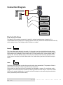
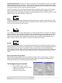
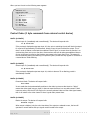
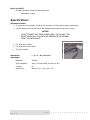
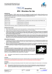
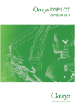
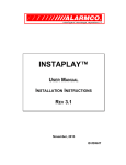
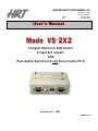
Hall Research Technologies, Inc
Phone:
Fax:
1163 Warner Ave.
Tustin, CA 92780
(714) 641-6607
(714) 641-6698
User’s Manual
Compact Electronic VGA Switch
2 input & 2 outputs
with
Push-button Switch Cord and Serial Control Port
September 27 , 2005
UMA1082 Rev. 1
Description
The Model VS-2X2 is a versatile, compact, high performance, solid-state, 2 input x 2 output, VGA video switch
that can operate at resolutions of up to 1600x1200.
The unit can be thought of as a 2 input x 1 output video switch followed by a 1 input x 2 output video splitter
built in one convenient box. It allows two monitors to be switched between two video sources. The unit is
housed in a small RFI shielded enclosure and is supplied with an AC power adapter, a push-button remote
switch control cable, and a Serial (RS-232) control cable for connecting to a PC or other serial control device.
The device terminates both video input signals and buffers the output in order to protect signal integrity. The
Model VS-2X2 can drive video cables to 150 feet or more (depending on cable quality and resolution setting).
The input and output connectors are all HD15 Female (standard VGA style).
Features
•
Allows two monitors to be switched between two video sources
•
Can be controlled manually, via Serial port, or from TTL level (or contact closure)
•
Select input 1, input 2, or blank the output
•
Auto mode automatically scans and selects the input with active video (Inputs can also be
prioritized)
•
Infinite switching cycle life
•
Can drive long cables
•
Terminates both video input signals and buffers the output to protect signal integrity
•
Includes push-button and serial cables for control
Setup
Your package should include two control cables, a power adapter, and the Video Switch unit itself. Please
take inventory of all items received and ensure that you have the above items.
Connect INPUT 1 and INPUT 2 of the switch to your video sources such as computer or notebook PC. You will
require a cable for each connection. It is highly recommended that you use multi-coaxial high-resolution VGA
cables for this purpose. The cables would generally be male-to-male. Hall Research can provide cables from 3
feet to 100 feet or more; please contact us for pricing information.
Connect the display devices such as a monitor (or a video projector) to the outputs of the Switch. You can
connect one or two monitors to the unit. Both will show the selected input.
Set the dip switches according to the mode of operation that best suits your application.
Connect the supplied AC power adapter to the Splitter, and plug-in the push-button switch cord.
Plug-and-Play
DDC (Direct Data Channel) is a standard by which a compatible monitor sends its identification and other
parameters to a PnP operating system such as Windows 98 etc. The VS-2X2 does not switch the PNP signal
lines to the PC.
This means that, in some instances, you may have to select a new monitor or video settings on your PC. Also
notice that most Notebook PC’s have a special function key to activate the external video output connector.
Page
1
of 6
........................
Connection Diagram
VS-2X2
Pushbutton
Switch Cord
- OR RS-232 Device
- OR TTL Level
- OR Automatic
Dip Switch Settings
The Model VS-2X2 provides a convenient dip switch for setting the desired mode of operation. It is
recommended to set the jumper prior to applying power to the unit, however the device does monitor the dip
switch settings when on and changes mode of operation as needed.
Normal:
This is the default mode setting for the switch. In this mode the unit is controlled from the push-button
switch cord. The switch at the end of the cable is momentary and it has a built-in LED. The LED is used to
indicate which input is selected. Solid on means Input 1, blinking means Input 2 (when blanking mode is
enabled, LED off means blanked output). Every time you press the button the output switches from the
current input to the other input. When blank mode is on, double clicking the button will blank the output
screen.
Auto:
If selected, causes the switch to select the input with active video automatically. The presence of video is
determined by examining the V.Sync signal of the input connectors.
In Auto mode you don’t need to have the pushbutton cord plugged in. However, if a push button cord is
plugged-in, the button itself cannot be used for switching, but the LED either stays on or blinks to indicate
which input is selected. Additionally, it is possible to blank the output in auto mode using the push-button
switch (see Blank dip switch function below)
Page
2
of 6
........................
Auto Mode with Priority: There are two modes of operation for the Auto-detection of video. In the default
mode (with dip switches as shown above – TTL switch in off position) no priority is assigned to either input.
Once the switch finds a video at one of the inputs it selects it and stops scanning until the currently selected
input's video is absent, then the switch will start scanning again.
If the TTL dip switch is down (on) at the same time as Auto, then priority is given to input #1. This means
that at any time video is present at input #1 the VS-2 will automatically select it, regardless of what is
happening at input #2. For example if the Switch is showing an image from input #2 and you plug in a video
signal to input #1, the switch will select #1 right away.
Blank:
If enabled, then double clicking the push-button will cause the output to go blank. If dip switch is off, then
the double click feature is not there and if the user presses the button in quick succession, all that the switch
will do is to switch between the inputs quickly!
TTL:
In this mode the selection of input is determined by an external contact closure or TTL signal. The customer
should provide his or her own cable. The signal is to be asserted between the tip and ground of the 3.5mm
mini-plug. A high (or open input) selects input #1 and a low (or short to ground) will select input #2. The
center ring of the connector can be used to light an external LED for indication of the selected channel if
desired. Simply tie the ring to the anode of an Led with the cathode tied to ground.
RS-232:
This position is to allow the switch to be controlled via a Serial device. The same CTRL connector is used to
attach the device to the serial port via a supplied cable. The unit operates at 1200 baud (adequate since only
single ASCII characters are used to command the switching, and the lower baud rate eliminates cable
length, shielding and noise issues). From the serial port you have full control over the operation of the switch
(e.g. select input 1, input 2, blank the output, un-blank the output, or place the switch in and out of automode).
More on Serial (RS-232) operation
Approximately one second after power-up, the VS-2X2 will output a menu on the serial port. To view the
menu you need a ASCII serial terminal or terminal emulator software. An example is Windows® Hyperterminal® (generally found in Accessories\Communication folder).
To Configure Hyper-terminal:
Page
3
•
Connect Direct to Com1 or Com2
•
Configure for 1200 Baud, 8 bits, No Parity,
1 Stop bit, No flow control
•
Settings per following figures:
of 6
........................
When you turn the unit on the following menu appears:
Version x.x
Copyright 200x
---------------------M E N U
---------------------1 = #1 Input
2 = #2 Input
a = Auto mode
b = Blank
u = Un-blank
----------------------
Control Codes (1 byte commands from external control device)
Ascii 1 (or Hex31)
Selects input #1 (immediately and unconditionally). The device will respond with:
In #1 Selected
If the previously displayed output was input #2, then prior to switching the unit will blank the output
for a period of approximately 25 milliseconds, switch to input #1 and un-blank the output. This is
done in order to reduce or eliminate the undesired “flash of junk” on screen when the monitor is resynchronizing from one input to the other. Most monitors and Lcd’s do take some additional time to
re-sync to the new input and so the blanking may appear to be longer than 25 ms. The reason for
the initial blanking during the switching is to prevent a jittery screen that may appear for a fraction of
a second due to initial switching.
Ascii 2 (or Hex32)
Selects input #2 (immediately and unconditionally). The device will respond with:
In #2 Selected
If the previously displayed output was input #1, similar to above a 25 ms blanking period is
automatically inserted.
Ascii a (or Hex61)
Enters Auto Mode. The device will respond with:
Auto Mode.
In auto mode the device automatically switches to the video input source that is active. “Active”
means that video signal has sync signal, it does not mean that there is a non-static screen! If both
inputs are active, then the VS-2X2 stays on the currently selected video until the video signal ceases,
then it will switch to the other channel if there is good video present there.
Ascii b (or Hex62)
Blanks the output. The device will respond with:
Blanked output
When output is blanked, only the color intensities of the output are reduced to zero, the box still
operates in normal fashion and sync signals are still routed to the output.
Page
4
of 6
........................
Ascii u (or Hex75)
Un-blanks the output. The device will respond with:
Unblanked output
Specifications
Equipment included:
•
UL approved 110 Vac adapter (12 Vdc @ 300 ma output on 2.5mm center positive coaxial plug)
•
(220 Vac adapters with CE approval are also available, please specify at the time of order).
NOTICE
DO NOT CONNECT ANY OTHER POWER SUPPLY TO THE UNIT. THE
DEVICE RELIES ON A FLOATING (NOT REFERENCED TO GROUND)
SUPPLY VOLTAGE SOURCE
•
6 ft, Serial Control Cable
•
6 ft, Push-button Switch Cable
•
This User’s Manual
Dimensions:
L x W x H: 4¼ x 2¾ x 1¼
Video Specs:
Page
5
Bandwidth:
250 MHz
Input impedance:
Video: 75 ohms on RGB, 330 ohms on H,V
Coupling:
DC
Signal Level:
Video: 0 to 0.7 v p-p , Sync.: TTL
of 6
........................
_________ Federal Communications Commission (FCC) Statement __________
This equipment generates, uses and radiates radio frequency energy and, if not installed and
used in accordance with the instructions, may cause harmful interference to radio
communications. This equipment has been designed to comply with the limits for a Class A
computing device, pursuant to Part 15 of the FCC rules. Harmful interference when operated
in a commercial environment. Operation of this equipment in a residential area is likely to
cause interference, in which case the user, at his own expense, will be required to take
whatever measures are necessary to correct the interference.
Warranty
HRT warrants that the supplied equipment is free from defective workmanship and material. Subject
to the agreements set forth, will repair or replace, at its option, the defective components for a
period of 2 years after purchase. The following conditions apply to the Warranty:
•
Warranty void if item subject to improper use, negligence, or unauthorized modification
•
Instructions must be followed in obtaining RMA number as explained below
•
Any defective part should be returned, insured and freight prepaid, to Hall Research, with the
following:
Return Material Authorization Number (RMA#)
Description of failure, as detailed as possible
Shipping address and contact name and phone number
Limited Liability
IN NO EVENT SHALL THE DIRECT VENDOR’S LIABLITY EXCEED THE PRICE PAID FOR THE
PRODUCT FROM DIRECT, INDIRECT, SPECIAL INCIDENTAL OR CONSEQUENTIAL DAMAGES
RESULTING FROM THE USE OF THE PRODUCT OR ITS DOCUMENTATION
Page
6
of 6
........................
Products Designed and Made in the USA
© Copyright 2006. Hall Research Technologies, Inc.
All rights reserved.
1163 Warner Ave., Tustin, CA 92780
Ph: (714) 641-6607, Fax: (714) 641-6698