1
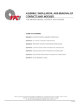
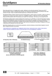
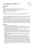
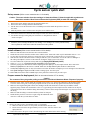
Cycle sensor quick start Set up sensor (Refer to user manual section 2.1 for details) Caution: The waste solution from the cartridges is Hazardous Waste. Follow the applicable regulations to discard the solution. Wear Personal Protective Equipment (PPE) to work with cartridges. 1. 2. 3. Remove the sensor and the spare parts kit from the plastic case. Remove the three cartridges from the fiberboard box. Put the sensor on its side and remove the seven Phillips screws that attach the protective sleeve to the sensor. Slide the protective sleeve off the sensor. Keep the screws and the sleeve. 4. 5. 6. Push on the stainless steel tab of the fluid couplet to make sure that it’s unlocked. Set the blue cartridge on the guide pins at location “S” and push down until it “clicks” into place. 7. Install the yellow cartridge and then the red cartridge. The cartridges are correctly installed if they can’t be pulled off of their bases unless the stainless steel tab is pushed. Install software (Refer to user manual section 2.2 for details) 1. 2. 3. 4. Make sure that the host PC has the latest Java version installed. Install the host software from the CD that comes with the sensor. Extract the whole .zip file and double-click on “.exe.” Use the cable from the spare parts kit to connect the sensor to the host PC serial port and a 12 V power supply. Start the host software. Select the host PC COM port that the Cycle is connected to. Use the PC’s Device Manager or the USB–serial adapter’s software to determine the COM port. Supply power to the sensor. 5. Go to the Tools menu of the host software and select the Deployment Wizard (Ctrl-D). 6. Select Autonomous or Synchronous file mode(SDI-12) then push Next. 7. Select the priming start date and time and the sampling start date and time. Set the sample interval. Put a value in the Number of Samples area. Do not leave it blank. Make sure the Skip Prime Cycle checkbox is not selected. 8. Set the Cal Frequency value. A value of less than 2 can reduce the number of samples per set of cartridges to less than 1000. 9. Push Send Settings to Cycle, then OK to make a settings report. Save the report. 10. Push Finish, then Yes to make a results report, then push Yes to add it to the previous report. Prepare sensor for deployment (Refer to user manual section 2.7 for details) Caution The contents of the syringe after pulling a vacuum are considered Hazardous Waste. Dispose of properly. 1. 2. 3. 4. Prime the sensor with a vacuum: attach the supplied syringe with a 1/16” barb to the outlet tube of R1. Pull the plunger to 10 mL. At the Settings tab, set the pump to operate for 100 cycles. Do this step again for the R2 and Cal cartridges. Make sure the reagent tubing that connects the cartridges and the inlet barbs does not have any air bubbles: Fill the supplied syringe with DI water and attach it to the 1/8” Tygon tubing from the sample hose barb. Push water to drip out of the bottom of the filters. Pinch the tubing and carefully connect it to the sample inlet barb again. Try not to let air into the tubing. Make sure that the tubing is wound around the eyebolts for transport. Install the blue protective outer sleeve again. Align the indentions on the outer sleeve with the eye bolts and screw holes. 5. Deploy the sensor (refer to user manual section 3.3 for details): Make sure that the sensor is in sleep mode, then disconnect the host cable. Put the sensor in a bucket in approximately 20 cm of water. Take the sensor to the deployment site. 6. Connect the sensor to the power source, then submerge the sensor in the bucket at the mooring. Cycle Quick Start Guide Revision B 20 Jan. 2014 Cycle sensor field service checklist Caution: The waste solution from the cartridges is Hazardous Waste. Follow the applicable regulations to discard the solution. Wear Personal Protective Equipment (PPE) to work with cartridges. Refer to the sections below in the user manual for details about these steps. Make sure the sensor is not on. Select “Stop” or “Stop Now” if the sensor is in low power (sleep) mode, or “Stop and Flush” if the sensor is in operation. 2. Remove the sensor from its deployment: be careful to keep air out of the sensor (section 3.4). 3. Remove the protective sleeve (section 5). 4. Connect the sensor to the host PC and power supply (section 2.1). 1. 5. Use a 2% cleaning solution of Micro-90 to clean the sensor (section 6.1): a. Pull the tubing straight off the hose barb. b. Unwrap the exhaust tubing from the top of the sensor and put one end into a beaker. c. Connect a syringe to a 25 cm length of 1/8” ID Tygon tubing. d. Use the syringe to fill the tubing. e. Connect the other end of the tubing to the “S” barb. f. Disconnect the syringe and put the old tubing it was connected to into the bottle of cleaning solution. g. Go to the Settings tab of the host software and push Flush. h. Let the solution soak in the sensor for ½ to 1 hour. 6. 7. 8. 9. 10. Change the reagent cartridges (section 6.2). Change the filters and screens (section 6.3). Clean sensor of macro-fouling (section 6.4). Flush the Micro-90 from the sensor (section 6.5). Use the vacuum prime procedure to reduce bubbles from cartridge installation (section 6.6). 11. 13. 14. 15. Clean and lubricate the bulkhead connectors (section 6.7). Fill the filters with DI water (section 2.7). Wrap the tubing around the eye hooks. Install the protective sleeve again (section 6.5). 15. Use the host software deployment wizard to set up the sensor for deployment (section 2.7) 16. Make sure that the sensor is in sleep mode, then disconnect the host cable (section 3.3). 17. Attach the sensor to its deployment mounting. 18. Connect the sensor to the deployment cable. 19. Make sure the outlet tubing flows has no blockages or kinks. 20. Attach a safety rope to one of the eye bolts. 21. Make sure the supplied power is sufficient for deployment (section 3.2). 22. Take the red reagent cartridge back to the laboratory to flush and send back to the manufacturer (section 6.8). Cycle Field Service Checklist Revision B 20 Jan. 2014