1
Wireless Access Point – N
(P/N DA1101)
Owner’s Manual
1308137 Rev. B
-i-
Federal Communications Commission Statement
This device complies with Part 15 of the FCC Rules and RSS-210 Issue 8 of Canada. Operation is
subject to the following two conditions:
•
This device may not cause harmful interference, and
•
This device must accept any interference received, including interference that may cause
undesired operation.
This equipment has been tested and found to comply with the limits for a class B digital device,
pursuant to Part 15 of the Federal Communications Commission (FCC) rules. These limits are
designed to provide reasonable protection against harmful interference in a residential installation.
This equipment generates, uses, and can radiate radio frequency energy and, if not installed and used
in accordance with the instructions, may cause harmful interference to radio communications.
However, there is no guarantee that interference will not occur in a particular installation. If this
equipment does cause harmful interference to radio or television reception, which can be determined
by turning the equipment off and on, the user is encouraged to try to correct the interference by one or
more of the following measures:
•
Reorient or relocate the receiving antenna.
•
Increase the separation between the equipment and receiver.
•
Connect the equipment into an outlet on a circuit different from that to which the receiver is
connected.
•
Consult the dealer or an experienced radio/TV technician for help.
Reprinted from the Code of Federal Regulations #47, part 15.193, 1993. Washington DC: Office of the Federal Register,
National Archives and Records Administration, U.S. Government Printing Office.
Canadian Department of Communications
This digital apparatus does not exceed the Class B limits for radio noise emissions from digital
apparatus set out in the Radio Interference Regulations of the Canadian Department of
Communications.
This Class B digital apparatus complies with Canadian ICES-003. Cet appareil numérique de la classe
B est conforme à la norme NMB-003 du Canada.
FCC Radio Frequency Exposure Caution Statement
In order to maintain compliance with the FCC RF exposure guidelines, this equipment should be
installed and operated with minimum distance 20cm between the radiator and your body. Use only
with supplied antenna. Unauthorized antenna, modification, or attachments could damage the
transmitter and may violate FCC regulations. Any changes of modifications not expressly approved by
the grantee of this device could void the users authority to operate the equipment.
Installation and use of this Wireless LAN device must be in strict accordance with the instructions
included in the user documentation provided with the product. Any changes or modifications (including
the antennas) made to this device that are not expressly approved by the manufacturer may void the
- ii -
user’s authority to operate the equipment. The manufacturer is not responsible for any radio or
television interference caused by unauthorized modification of this device, or the substitution or
attachment of connecting cables and equipment other than manufacturer specified. It is the
responsibility of the user to correct any interference caused by such unauthorized modification,
substitution or attachment. Manufacturer and its authorized resellers or distributors will assume no
liability for any damage or violation of government regulations arising from failing to comply with these
guidelines.
This device and its antenna(s) must not be co-located or operating in conjunction with any
other antenna or transmitter.
Declaration of Conformity (R&TTE directive 1999/5/EC)
The following items were completed and are considered relevant and sufficient:
•
Essential requirements as in [Article 3]
•
Protection requirements for health and safety as in [Article 3.1a]
•
Testing for electric safety according to [EN 60950]
•
Protection requirements for electromagnetic compatibility in [Article 3.1b]
•
Testing for electromagnetic compatibility in [EN 301 489-1] & [EN 301]
•
Testing according to [489-17]
•
Effective use of the radio spectrum as in [Article 3.2]
•
Testing for radio test suites according to [EN 300 328-2]
WARNING: TO PREVENT FIRE OR SHOCK HAZARD, DO NOT EXPOSE THIS PRODUCT TO
RAIN OR MOISTURE. THE UNIT MUST NOT BE EXPOSED TO DRIPPING OR SPLASHING
WATER.
CAUTION: DO NOT OPEN THE UNIT. DO NOT PERFORM ANY SERVICING OTHER THAN THAT
CONTAINED IN THE INSTALLATION AND TROUBLESHOOTING INSTRUCTIONS. REFER ALL
SERVICING TO QUALIFIED SERVICE PERSONNEL.
CAUTION: THIS DEVICE MUST BE INSTALLED AND USED IN STRICT ACCORDANCE WITH
THE MANUFACTURER’S INSTRUCTIONS AS DESCRIBED IN THE USER DOCUMENTATION
THAT COMES WITH THE PRODUCT.
WARNING: POSTPONE INSTALLATION UNTIL THERE IS NO RISK OF THUNDERSTORM OR
LIGHTNING ACTIVITY IN THE AREA.
When using this device, basic safety precautions should always be followed to reduce the risk of fire,
electric shock and injury to persons, including the following:
• Read all of the instructions {listed here and/or in the user manual} before you operate this
equipment.
• Give particular attention to all safety precautions.
- iii -
• Retain the instructions for future reference.
• Comply with all warning and caution statements in the instructions.
• Observe all warning and caution symbols that are affixed to this equipment.
• Comply with all instructions that accompany this equipment.
• Avoid using this product during an electrical storm. There may be a risk of electric shock from
lightning. For added protection for this product during a lightning storm, or when it is left
unattended and unused for long periods of time, unplug the power supply, and disconnect the Cat
5e to the N-WAP at the POE Inserter. This will prevent damage to the product due to lightning and
power surges. It is recommended that the customer install an AC surge protector in the AC outlet
to which this device is connected. This is to avoid damaging the equipment by local lightning
strikes and other electrical surges. A Data Surge Conditioning Unit is also available from Legrand
(P/N 364598-01) to help protect the data connection from the POE Injector to the N-WAP.
• Operate this product only from the type of power source indicated on the product’s marking label.
• If you are not sure of the type of power supplied to your home, consult your dealer or local power
company.
• Upon completion of any service or repairs to this product, ask the service technician to perform
safety checks to determine that the product is in safe operating condition.
Installation of this product must be in accordance with national wiring codes and conform to local
regulations.
Place POE Inserter to allow for easy access when disconnecting the power cord/adapter of the device
from the AC wall outlet.
Wipe the unit with a clean, dry cloth. Never use cleaning fluid or similar chemicals. Do not spray
cleaners directly on the unit or use forced air to remove dust.
When not utilizing the recommended 3-gang or 1-gang plastic switch & outlet box, do not directly
cover the device, or block the airflow to the device with insulation or any other objects.
Keep the device away from excessive heat and humidity and keep the device free from vibration and
dust.
- iv -
TABLE OF CONTENTS
Chapter 1 Introduction ....................................................................................................................... 1 Overview ...................................................................................................................................... 1 Package Content ......................................................................................................................... 1 Physical Details ........................................................................................................................... 1 Chapter 2 Physical Installation .......................................................................................................... 3 Physical Installation Steps .......................................................................................................... 3 Chapter 3 Network Settings ............................................................................................................... 4 Configuring and monitoring your DA1101 from web browser ................................................. 4 Using the DA-Discovery.exe program for configuration of the DA1101 .................................... 4 Running the Setup Wizard / Default AP Mode Overview .......................................................... 6 Operation Mode Selection........................................................................................................... 8 Client Mode Overview .............................................................................................................. 8 Repeater Mode Overview ....................................................................................................... 11 LAN Interface Setup ............................................................................................................... 12 WAN Interface Setup ............................................................................................................. 13
DHCP Client ................................................................................................................... 14
Static IP .......................................................................................................................... 15
PPPoE ............................................................................................................................ 16
PPTP .............................................................................................................................. 17
L2TP ............................................................................................................................... 18
Chapter 4 Firewall ............................................................................................................................. 20 Port Filtering .......................................................................................................................... 20 IP Filtering .............................................................................................................................. 21 MAC Filtering ......................................................................................................................... 22 Port Forwarding ..................................................................................................................... 23 URL Filtering .......................................................................................................................... 24 DMZ ....................................................................................................................................... 25 VLAN ..................................................................................................................................... 26 Chapter 5 Wireless Settings ............................................................................................................ 27 Basic Settings ........................................................................................................................ 27 Advanced Settings ................................................................................................................. 30 Security Setup........................................................................................................................ 32 Access Control ....................................................................................................................... 35 WDS Settings......................................................................................................................... 36 Site Survey ............................................................................................................................ 36 Wireless Schedule ................................................................................................................. 37
-v-
Chapter 6 Management .................................................................................................................... 38 Status ..................................................................................................................................... 38 Statistics................................................................................................................................. 39 DDNS..................................................................................................................................... 39 Time Zone Setting .................................................................................................................. 40 Denial-of-Service ................................................................................................................... 41 Log ......................................................................................................................................... 42 Upgrade Firmware ................................................................................................................. 43 Save / Reload Settings........................................................................................................... 43 Password Setup ..................................................................................................................... 44 Chapter 7 QoS................................................................................................................................... 45 Enable QoS ........................................................................................................................... 45 QoS Rule Setting ................................................................................................................... 46 Chapter 8 Route Setup ..................................................................................................................... 47 Dynamic Route ...................................................................................................................... 47 Static Route ........................................................................................................................... 48 Appendix A Frequently Asked Questions ......................................................................................... A
Appendix B DA1101 Specifications ................................................................................................... B Appendix C DA1101 Utility Program ................................................................................................. C Appendix D Manual logon to DA1101 for configuration .................................................................. D Appendix E DA1101 Mounting Information & Best Practices .......................................................... E - vi -
Chapter 1
Introduction
Overview
Integrating the cutting edge of Internet Telephony and Access Point manufacturing experience, Legrand
now introduces the latest member of our Wireless Access Point family: the DA1101 N-WAP.
The N-WAP provides high-performance Access Point (AP) function for flexible wireless communication.
With built-in IEEE 802.11b/g/n wireless network capability, the N-WAP allows any computer and wireless
enabled network client connect to it without additional cabling. The 802.11n wireless capability gives
users the highest speed of wireless experience ever. With an 802.11n compatible wireless adapter
installed in your PC, the files can be transferred at up to 300Mbps. The radio coverage is also doubled to
offer the high speed wireless connection in an even wider space of your office or house.
To secure the wireless communication, the N-WAP supports most up-to-date encryption: WEP, WPAPSK and WPA2-PSK. In addition, the N-WAP supports WPS configuration with PBC/PIN type for users
to connect to a secured wireless network easily.
Product Features
IEEE 802.11b/g/n wireless standard compliant
Multi-mode: AP, Client, Repeater and Router Mode
Supports 64/128-bit WEP, WPA, WPA-PSK, WPA2, WPA2-PSK and 802.1x encryption
Package Content
The contents of your product package should include the following items:
DA1101 802.11n Wireless Access Point
POE Module w/AC adapter
Installation Bracket
Round and Rectangular Cover
Installation/Instruction Sheet
A CD containing this manual and a utility (PC-based .exe file) used to find the N-WAP’s IP address
given to it by the router it is attached to (AP Mode). See Appendix C for more detail.
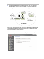
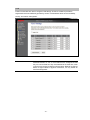
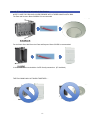
Physical Details
The following figure illustrates the 3-gang (round) and 1-gang (rectangular) versions of an installed
DA1101 N-WAP. For additional mounting information and best practices suggestions, refer to Appendix
E.
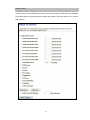
-1-
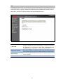
Reset Button
Access
LED Indicators
LED Indicators:
LED
Color
Ethernet
Green
Power
Blue/Orange
WiFi
Green/Red
State
Solid Green
Blinking Green
Blue
Solid Orange
Blinking Orange
Solid Green
Blinking Green
Red
Descriptions
Power Present
Ethernet Active
Power OK
Initializing
Signal Survey
Connected
Streaming in Session
No WiFi Signal
Reset Button:
The DA1101 has a reset button accessible through either cover or with the cover off that can be pushed
and held for 10 seconds to reset the DA1101 to factory default condition (the IP address is reset to
192.168.40.253). To find the IP address of an installed and working N-WAP, run the utility program
provided on the CD included with the product (see Appendix C).
Reset Button
LED Indicators
-2-
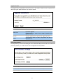
Chapter 2
Physical Installation
Physical Installation Steps
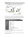
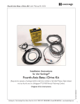
This chapter illustrates the physical installation of the DA1101 Wireless Access Point –N.
1. Run a Category 5 cable from the triple-gang or single-gang
electrical box at the intended DA1101 room location to the
POE module located in the structured wiring enclosure.
2. Make sure that the Power Supply is not connected to the
POE module at this time.
Single-gang bracket
3. Pull the Category 5 cable out from the electrical box through
the supplied triple-gang or modified into a single-gang
RJ45 jack
bracket and attach the bracket to the associated electrical
box with the supplied screws.
4. Terminate the Cat 5 cable with an RJ45 plug and
connect it to the RJ45 jack on the DA1101. The DA1101
is then snapped into the mounting bracket by first
slots
inserting the two tabs on one end into the slots on the
bracket and tilting it until it is flush with the bracket,
where it should snap into place.
Triple-gang bracket
5. If this is a triple-gang installation, line the feet on the
triple gang bracket up with the indentions inside the
round cover, and snap that cover in place. There is a
protrusion inside the round cover that allows it only to be
installed in the correct orientation. If this is a single-gang
installation, simply hang the top of the rectangular cover
on the single-gang bracket and tilt the cover to snap it
into place.
Cat 5 to router
6. In the enclosure, terminate the other end of the Cat 5
Cat 5 to N-WAP
cable from the DA1101 with an RJ45 plug and connect it
to the POE output RJ45 jack. A Cat 5 jumper is run from
the POE input jack to a local router port.
7. Plug the power supply into the POE module and into an
AC outlet, and refer to the next chapter for software
configuration and operation information.
Power in from AC adapter
-3-
Chapter 3
Network Settings
Configuring and monitoring your DA1101 from web browser
The DA1101 integrates a web-based graphical user interface that can cover most configurations and
machine status monitoring. Via a standard web browser, you can configure and check machine status
from anywhere around the world.
NOTE: The DA1101 is designed as a DHCP device, which means it automatically gets an IP
address from the router it is attached to. It is defaulted to AP mode (meaning it acts as a
wireless Access Point for wireless devices around the home, like laptops) and those devices
also get their IP address from the router that the DA1101 is attached to. No configuration is
required for basic operation.
WARNING: By default, there is no security configured, which means anyone within range (even
outside your home) can access your internet connection. To restrict access (configure
security) or operate in a different mode other than AP, you must log onto your DA1101. To do
this you must know its IP address, and we have provided a utility program for you to find the
DA1101’s IP address.
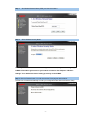
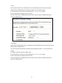
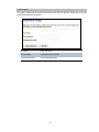
Using the DA-Discovery.exe program for configuration of the DA1101
The executable file “DA-Discovery.exe” is found on the CD provided with this product, and should be
copied onto the desktop (or a known location) on the PC normally used for N-WAP configuration.
With the PC set for DHCP (TCP/IP Settings), and connected to the router used for the N-WAP, simply
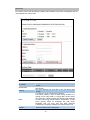
run (double click) the utility program and the screen shown below will appear.
-4-
Click on the “Refresh” button, and the screen will be updated to show the IP addresses of all devices
attached to the router, including the DA1101.
To configure the N-WAP simply highlight the DA1101 that you wish to connect to and click on the
“Connect to Device” button and you will be shown the logon screen shown below.
Simply type in “admin” for the logon and “admin” for the password to logon to the DA1101.
NOTE: If you are not attached to a router which provides you with an IP address, you may still
manually logon to the DA1101 by performing the steps show in Appendix D, and if successful
will end up at the same logon screen shown above.
When you successfully logon, you’ll be shown a screen where you can run the Setup Wizard, or opt to
select a different function on the left side of the screen for manual setup. First, we’ll go through the
simple Setup Wizard for AP Mode.
-5-
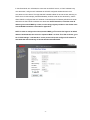
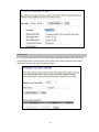
Running the Setup Wizard / Default AP Mode Overview
The N-WAP automatically powers up in AP (Access Point) Mode, which is the default mode
where the N-WAP is attached to a router, like our DA1004. The router then provides DHCP
addressing (IP addresses) to any wirelessly connected devices (PCs).
In this AP Mode, the router acts as the DHCP server, so if its IP address is say 192.168.40.254, it will
give out IP addresses to all DHCP configured wireless devices in that 192.168.40.xxx sub network,
including the DA1101 and all wirelessly attached PCs.
Select the Setup Wizard on the left side of the screen and by clicking on Next on the Setup Wizard
screen shown below, you will then name your N-WAP and setup its security.
-6-
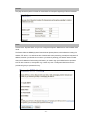
Step 1.
Set Wireless Network Name (SSID), and then click Next>>.
Step 2.
Select Wireless Security Mode.
NOTE: If you elect to select “None” for security as shown above, anyone within range of your
N-WAP will be able to gain access to your network connection. See Chapter 5 “Wireless
Settings” for a detailed overview of setting up security on the N-WAP.
Step 3. Click the Finished button. You will then see the Finish page as shown below.
The DA1101 will reboot automatically to make your configuration take effect and finish the Setup.
-7-
Operation Mode Selection
Besides AP Mode, there are three other Operational Modes that the N-WAP can be configured to
support; Client Mode, Repeater Mode and Router Mode. Since most customers have a router already,
and since we also sell a router (the DA1004), this manual will not cover that infrequently used mode.
To get to the other modes, select “Operation Mode” from the left side of the screen and you’ll see the
following screen:
NOTE: Repeater Mode is not selected from the Operation Mode screen, as it is a functional
superset of the Client Mode, and is selected from the “Wireless” “Basic Settings” screen on an
N-WAP which is already in Client Mode, so first, let’s go over the use of Client Mode.
Client Mode Overview
Client Mode is used where a second DA1101 N-WAP is configured as a wireless remote client of
the original N-WAP and connects directly to a LAN or PC (no wireless devices), while the original
N-WAP connects to the router as in AP Mode. This could be useful if you have one or more PCs
without wireless interfaces in a location within wireless range of your first N-WAP, but not easily
hardwired to the original N-WAP location (ie. a boathouse or guard shack).
-8-
In this Client Mode, as in AP Mode, the router acts as the DHCP server, so if its IP address is say
192.168.40.254, it will give out IP addresses to all DHCP configured wireless devices in that
192.168.40.xxx sub network. The original N-WAP’s default address is 192.168.40.253, assuming no
DHCP server for this example, (the Default Gateway is still the router at 192.168.40.254.), and the
Client N-WAP is configured with an IP address of 192.168.40.252. Its Gateway will still be the router
attached to the first N-WAP at address 192.168.40.254. NOTE: Remember, to find the actual IP
address given to the N-WAP by a router, use the utility program provided on the CD that came
with the N-WAP and which is described in Appendix C.
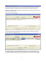
NOTE: In order to configure the Client (second N-WAP), you’ll need to first logon to its default
address 192.168.40.253, then select its “Operation Mode” as Client. Then after it reboots, go to
the “TCP/IP Settings” “LAN Interface” screen (shown below) and configure its IP address as
192.168.40.252 and its Gateway as 192.168.40.254 and disable DHCP.
-9-
You’ll also need to go to the “Wireless” “Basic Settings” screen (shown below), and change the SSID
to something different than what you called the original N-WAP, and change its Network Type to
“Infrastructure”.
You’ll then need to go to the “Wireless” “Site Survey” screen and click “Site Survey” to search for the
original N-WAP. Once you find it, select it (as shown below), and click “Next”.
Then just click on “Connect”. This tells the second N-WAP that he is a Client of the original N-WAP. At
this point, the PC/s attached to the second N-WAP should be able to be configured to get IP
addresses from the router, through the original N-WAP. Also, if you go to “Wireless” “Basic Settings”,
you should notice that the SSID of the second N-WAP has changed to that of the original N-WAP, and
if you go to the original N-WAP “Wireless” “Basic Settings” “Show Active Clients” screen, you should
be able to see the second N-WAP has been connected to the original N-WAP.
- 10 -
Repeater Mode Overview
Repeater Mode (also called Client + AP Mode) is similar to Client Mode, but in this case the
second N-WAP can support wireless devices within range to its location. Effectively, this is a
range expansion of the original N-WAP, by using the second N-WAP as a repeater.
To get to Repeater Mode, your second N-WAP must already be configured in Client Mode (see
previous section), then go to “Wireless” “Basic Settings” and select “Enable Universal Repeater Mode
(Acting as AP and Client simultaneously)”, as shown on the screen below. You’ll also need to fill out
the “SSID of Extended Interface” with the SSID that you gave the second N-WAP.
This completes the overview of the Setup Wizard, and the various Modes that are used by the
DA1101 for typical residential networks.
The following screens provide more detailed information on many of the previously discussed settings
and their associated parameters.
- 11 -
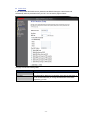
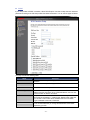
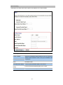
LAN Interface Setup
This page is used to configure the parameters for local area network which connects to the LAN port
of your DA1101. Here you may change the setting for IP address, subnet mask, DHCP, etc..
IP Address
LAN IP Address of the DA1101
Default : 192.168.40.253
Subnet Mask
LAN mask of the DA1101
Default : 255.255.255.0
DHCP Server
You can select Server or Disable. If you select Disable, the
DHCP service of LAN port is disabled.
Default : Server
DHCP Client Range
The first and last IP address that DHCP server assigns.
Default : 192.168.40.100 – 192.168.40.200
Static DHCP
It allows you reserve IP addresses, and assign the same IP
address to the network device with the specified MAC address
any time it requests an IP address
Default : Disable
Domain Name
Set three alternatives Domain Name Server for LAN interface.
Default : Null
802.11d Spanning Tree
Spanning Tree Protocol. You can select Enable or Disable.
Default : Disable
- 12 -
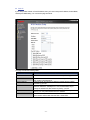
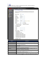
WAN Interface Setup
Choose menu “TCP/IP Settings→WAN Interface”, you can configure the IP parameters of the WAN on
the screen below when router mode is enabled.
WAN Access Type
DHCP Client
Connections
assignment.
Static IP
Connections which use static IP address assignment.
PPPoE
PPTP
L2TP
which
use
dynamic
IP
address
Connections which use PPPoE that requires a user
name and password.
Connections which use a Point-to-Point Tunneling
Protocol (PPTP) connection.
Connections which use a Layer2 Tunneling Protocol
(L2TP) connection.
Attain DNS Automatically
Select to attain DNS automatically from your ISP.
Set DNS Manually
Select to specify your own preferred DNS Server IP address.
The DNS 2 or DNS 3 is optional. You can enter the secondary and the
third DNS Server’s IP address as an alternative of DNS 1.
Clone MAC Address
Your ISP may require a particular MAC address in order for you to
connect to the Internet. This MAC address is the PC’s MAC address
that your ISP had originally connected your Internet to. Type in this
section to replace the WAN MAC address with the MAC address of that
PC.
Enable IGMP Proxy
Enable Ping Access on
WAN
Enable Web Server Access
on WAN
Enable IPsec pass through
on VPN connection
Enable PPTP pass through
on VPN connection
Enable L2TP pass through
on VPN connection
Enable IPv6 pass through
on VPN connection
Check to enable the IGMP Proxy function.
Check to enable the Ping Access on WAN function.
Check to enable the Web Server Access on WAN function.
Check to enable the IPsec pass through on VPN connection function.
Check to enable the PPTP pass through on VPN connection function.
Check to enable the L2TP pass through on VPN connection function.
Check to enable the IPv6 pass through on VPN connection function.
Apply Changes
After completing the settings on this page, click Apply changes button
to save the settings.
Reset
Click Reset to restore to default values.
- 13 -
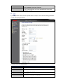
DHCP Client
If your ISP provides the DHCP service, please choose DHCP Client type, and the Router will
automatically obtain IP parameters from your ISP. You can see the page as follows.
The page includes the following fields:
Object
Host Name
Description
This option specifies the Host Name of the Router.
MTU Size
The default MTU (Maximum Transmission Unit) value is 1492 Bytes. It
is not recommended that you change the default MTU Size unless
required by your ISP.
- 14 -
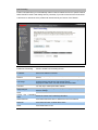
Static IP
If your ISP provides a static or fixed IP Address, then you have to setup the IP address, Subnet Mask,
Gateway and DNS setting. You can see the page as follows.
The page includes the following fields:
Object
IP Address
Description
Enter the IP address in dotted-decimal notation provided by your ISP.
Subnet Mask
Enter the subnet Mask in dotted-decimal notation provided by your
ISP, usually is 255.255.255.0
(Optional) Enter the gateway IP address in dotted-decimal notation
provided by your ISP.
The normal MTU (Maximum Transmission Unit) value for most
Ethernet networks is 1500 Bytes. It is not recommended that you
change the default MTU Size unless required by your ISP.
Enter the DNS server IP address provided by your ISP, or you can
specify your own preferred DNS server IP address.
You can enter another DNS server’s IP address as a backup. DNS 2
and 3 servers will be used when the DNS 1 server fails.
Default Gateway
MTU Size
DNS 1
DNS 2 & DNS 3
- 15 -
PPPoE
If your ISP provides a PPPoE connection, select PPPoE option. User has to setup the user name and
password according to the ISP that provided the related information. You can see the page as follows.
The page includes the following fields:
Object
User Name
Password
Description
Enter the User Name provided by your ISP. This field is casesensitive.
Enter the Password provided by your ISP. This field is case-sensitive.
Service Name
Enter the Internet service provider name in this field.
Connection Type
Select the connection type Continuous, Connect on Demand or
Manual from the drop-down menu. If selected Manual, user can click
Connect button to make a connection.
It represents that the device will idle after the minutes you set. The
time must be set between 1~1000 minutes. Default value of idle time
is 5 minutes. This function will be available when the Connection
Type is selected to Connect on Demand.
The default MTU (Maximum Transmission Unit) value is 1452 Bytes. It
is not recommended that you change the default MTU Size unless
required by your ISP.
Idle Time
MTU Size
- 16 -
PPTP
If your ISP provides PPTP connection, please select PPTP option. And enter the following
parameters. You can see the page as follows.
The page includes the following fields:
Object
IP Address
Description
Enter the IP address in dotted-decimal notation provided by your ISP.
Subnet Mask
Enter the subnet Mask in dotted-decimal notation provided by your
ISP, usually is 255.255.255.0
Enter the PPTP Server IP address in dotted-decimal notation provided
by your ISP.
Enter the User Name provided by your ISP. The Maximum input is 20
alphanumeric characters (case-sensitive).
Enter the Password provided by your ISP. The Maximum input is 32
alphanumeric characters (case-sensitive).
Select the connection type Continuous, Connect on Demand or
Manual from the drop-down menu. If selected Manual, user can click
Connect button to make a connection.
It represents that the device will idle after the minutes you set. The
time must be set between 1~1000 minutes. Default value of idle time
Server IP Address
User Name
Password
Connection Type
Idle Time
- 17 -
MTU Size
is 5 minutes. This function will be available when the Connection
Type is selected to Connect on Demand.
The default MTU (Maximum Transmission Unit) value is 1460 Bytes. It
is not recommended that you change the default MTU Size unless
required by your ISP.
L2TP
If your ISP provides L2TP connection, please select L2TP option. And enter the following parameters.
You can see the page as follows.
The page includes the following fields:
Object
IP Address
Description
Enter the IP address in dotted-decimal notation provided by your ISP.
Subnet Mask
Enter the subnet Mask in dotted-decimal notation provided by your
ISP, usually is 255.255.255.0
Enter the L2TP Server IP address in dotted-decimal notation provided
by your ISP.
Enter the User Name provided by your ISP. The Maximum input is 20
alphanumeric characters (case-sensitive).
Server IP Address
User Name
- 18 -
Password
Connection Type
Idle Time
MTU Size
Enter the Password provided by your ISP. The Maximum input is 32
alphanumeric characters (case-sensitive).
Select the connection type Continuous, Connect on Demand or
Manual from the drop-down menu. If selected Manual, user can click
Connect button to make a connection.
It represents that the device will idle after the minutes you set. The
time must be set between 1~1000 minutes. Default value of idle time
is 5 minutes. This function will be available when the Connection
Type is selected to Connect on Demand.
The default MTU (Maximum Transmission Unit) value is 1460 Bytes. It
is not recommended that you change the default MTU Size unless
required by your ISP.
- 19 -
Chapter 4
Firewall
Port Filtering
Entries in this table are used to restrict certain types of data packets from your local network to
Internet through the DA1101. Use of such filters can be helpful in securing or restricting your local
network.
Enable Port Filtering
Port Range
Protocol
Check to enable Port Filtering function.
Enter the beginning of the range of port numbers used by the service. If
the service uses a single port number, enter it in both the start and finish
fields.
Select the protocol (TCP, UDP or Both) used to the remote system or
service.
Comment
You may key in a description MAC address.
Apply Changes
After completing the settings on this page, click Apply Changes button to
save the settings.
Reset
Click Reset button to restore to default values.
Current Filter Table
Shows the current Port Forwarding information.
Delete Selected
Click Delete Selected button to delete items which are selected.
Delete All
Click Delete All button to delete all the items.
Reset
Click Reset button to reset.
- 20 -
IP Filtering
Entries in this table are used to restrict certain types of data packets from your local network to
Internet through the DA1101. Use of such IP filters can be helpful in securing or restricting your local
network.
Enable IP Filtering
Check to enable IP filtering function.
Local IP Address
Enter the local computer’s IP address.
Protocol
Select the protocol (TCP, UDP or Both) used to the remote system or
service.
Comment
You may key in a description for the port range.
Apply Changes
After completing the settings on this page, click Apply Changes button to
save the settings.
Reset
Click Reset button to restore to default values.
Current Filter Table
Shows the current IP filter information.
Delete Selected
Click Delete Selected button to delete items which are selected.
Delete All
Click Delete All button to delete all the items.
Reset
Click Reset button to rest.
- 21 -
MAC Filtering
Entries in this table are used to restrict certain types of data packets from your local network to
Internet through the DA1101. Use of such filters can be helpful in securing or restricting your local
network.
Enable MAC Filtering
Check to enable MAC filtering function.
MAC Address
Enter the client MAC address in the field.
Comment
You may key in a description MAC address.
Apply Changes
After completing the settings on this page, click Apply Changes button to
save the settings.
Reset
Click Reset button to restore to default values.
Current Filter Table
Shows the current MAC filter information.
Deleted Selected
Click Delete Selected button to delete items which are selected.
Deleted All
Click Delete All button to delete all the items.
Reset
Click Reset button to rest.
- 22 -
Port Forwarding
Entries in this table allow you to automatically redirect common network services to a specific machine
behind the NAT firewall. These settings are only necessary if you wish to host some sort of server like
a web server or mail server on the private local network behind your DA1101's NAT firewall.
Enable Port Forwarding
Check to enable Port Forwarding function.
IP Address
Enter the IP address in the field.
Select the protocol (TCP, UDP or Both) used to the remote system or
service.
For TCP and UDP Services, enter the beginning of the range of port
numbers used by the service. If the service uses a
single port number, enter it in both the start and finish fields.
Protocol
Port Range
Comment
You may key in a description MAC address.
Apply Changes
After completing the settings on this page, click Apply Changes button to
save the settings.
Reset
Current
Table
Click Reset button to restore to default values.
Port
Forwarding
Shows the current Port Forwarding information.
Delete Selected
Click Delete Selected button to delete items which are selected.
Delete All
Click Delete All button to delete all the items.
Reset
Click Reset button to rest.
- 23 -
URL Filtering
URL filter is used to deny LAN users from accessing the internet. Block those URLs which contain
keywords listed below.
Enable URL Filtering
Check to enable URL filtering function.
URL Address
Enter the URL address in the field.
Apply Changes
After completing the settings on this page, click Apply Changes button to
save the settings.
Reset
Click Reset button to restore to default values.
Current Filter Table
Shows the current URL address filter information.
Delete Selected
Click Delete All button to delete all the items.
Reset
Click Reset button to rest.
- 24 -
DMZ
A Demilitarized Zone is used to provide Internet services without sacrificing unauthorized access to its
local private network. Typically, the DMZ host contains devices accessible to Internet traffic, such as
Web (HTTP ) servers, FTP servers, SMTP (e-mail) servers and DNS servers.
Enable DMZ
Check the box to enable DMZ function. If the DMZ Host Function is
enabled, it means that you set up DMZ host at a particular computer to
be exposed to the Internet so that some applications/software,
especially Internet / online game can have two way connections.
DMZ Host IP Address
Enter the IP address of a particular host in your LAN which will receive
all the packets originally going to the WAN port/Public IP address above.
Apply Changes
After completing the settings on this page, click Apply Changes button to
save the settings.
Reset
Click Reset button to restore to default values
- 25 -
VLAN
Entries in below table are used to configure VLAN settings. VLANs are created to provide the
segmentation services traditionally provided by routers. VLANs address issues such as scalability,
security, and network management.
Enable VLAN
VLAN (Virtual Local Area Network) refers to a group of logically
networked devices on one or more LANs that are configured so that
they can communicate as if they were attached to the same wire, when
in fact they are located on different LAN segments. Because VLANs are
based on logical instead of physical connections, it is very flexible for
user/host management.
- 26 -
Chapter 5
Wireless Settings
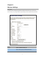
Basic Settings
This page is used to configure the parameters for wireless LAN clients who may connect to your
DA1101. Here you may change wireless encryption settings as well as wireless network parameters.
Disable Wireless LAN
Interface
Band
Enable or disable the wireless LAN.
There are 6 modes: 2.4GHz (B), 2.4GHz (G), 2.4GHz (N), 2.4GHz
(B+G), 2.4GHz (G+N), and 2.4GHz (B+G+N) mode.
Default : 2.4GHz (B+G+N)
- 27 -
Mode
- AP: The DA1101 functions as a wireless hub to which wireless
clients can connect. The clients must make sure that they are
configured to match the DA1101’s wireless settings. The DA1101
must be connected to a router for wireless devices to receive
DHCP addressing.
- WDS: WDS operation as defined by the IEEE802.11 standard has
been made available. Using WDS it is possible to wirelessly
connect DA1101s, and in doing so extend a wired infrastructure to
locations where cabling is not possible or inefficient to implement.
- AP+WDS: It means the device can support WDS and AP Mode
simultaneously.
Default : AP mode
Network Type -
- Infrastructure: The wireless LAN serves as a wireless station
(infrastructure). Connected to a PC or a small LAN (no more than
5 PCs), it allows the PC or small LAN to be able to access the
wireless network via the DA1101.
- Ad hoc: The wireless LAN will use the Ad hoc mode to operate.
SSID
Wireless stations associating to the DA1101 must have the same
SSID. Enter a descriptive name for the wireless LAN.
Default : 802.11bgn-SSID
Channel Width
There are 20MHz and 40MHz bandwidths for cohesion
Default : 20MHz
Control Sideband
Specify if the extension channel should be in the Upper or Lower
sideband
Default : Upper (Unavailable)
Channel Number
Select the appropriate channel from the list provided to correspond
with your network settings. Channels differ from country to country.
Default : 6
Broadcast SSID
If you enable “Broadcast ESSID”, every wireless station located
within the coverage of this DA1101 can discover this DA1101 easily.
If you are building a public wireless network, enabling this feature is
recommended. In private network, disabling “Broadcast ESSID” can
provide better security.
Default : Enable
WMM
The short of Wi-Fi Multi-Media, it will enhance the data transfer
performance of multimedia contents when they’re being transferred
over wireless network.
Default : Enable (Unavailable)
Data Rate
The Data Rate is the rate of data transmission for 802.11b/g/n
clients. The DA1101 will use the highest possible selected
transmission rate to transmit the data packets.
Default : Auto
Default : Auto
Associated Clients
Enable Mac Clone
To show the MAC address, transmission, reception packet counters
and encrypted status for each associated wireless client.
When set at Client mode, it provides wireless LAN to connect to a
MAC address.
Default : Disable
- 28 -
Enable Universal Repeater Universal Repeater is a technology used to extend wireless
Mode
coverage. If this is enabled, a second DA1101 can be used for
directly connected LAN devices and wireless devices.
Default : Disable
SSID of Extended Interface Click on “Enable Universal Repeater Mode”; In the “SSID of
Extended Interface”, enter the SSID of the wireless router that you
want to extend.
Default : Null
- 29 -
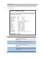
Advanced Settings
These settings are only for more technically advanced users who have a sufficient knowledge about
wireless LAN. These settings should not be changed unless you know what effect the changes will
have on your DA1101.
Fragment Threshold
“Fragment Threshold” specifies the maximum size of packet during
the fragmentation of data to be transmitted. If you set this value too
low, it will result in bad performance.
Default : 2346
RTS Threshold
When the packet size is smaller the RTS threshold, the DA1101 will
not use the RTS/CTS mechanism to send this packet.
Default : 2347
Beacon Interval
The interval of time that this DA1101 broadcast a beacon. Beacon is
used to synchronize the wireless network.
Default : 100
Preamble Type
Preamble type defines the length of CRC block in the frames during
the wireless communication. “Short Preamble” is suitable for high
traffic wireless network. “Long Preamble” can provide more reliable
communication.
Default : Long Preamble
- 30 -
IAPP
Inter-Access Point Protocol is a recommendation that describes an
optional extension to IEEE 802.11 that provides wireless accesspoint communications among multivendor systems.
Default : Enable
Protection
It is recommended to enable the protection mechanism. This
mechanism can decrease the rate of data collision between 802.11b
and 802.11g wireless stations. When the protection mode is
enabled, the throughput of the AP will be a little lower due to many
of frame traffic should be transmitted.
Default : Enable
Aggregation
It is a function where the values of multiple rows are grouped
together.
Default : Enable
Short GI
It is used to set the time that the receiver waits for RF reflections to
settle out before sampling data.
Default : Enable
WLAN Partition
This feature also called WLAN isolation or Block Relay. If this
feature is disabled, then there is no barrier between communications
among wireless stations connecting to the Access Point, i.e the
DA1101. If this is enabled, wireless stations of the selected band are
not allowed to exchange data through the DA1101. The default
value is set to 'Disabled'.
Default : Disable
RF Output Power
Users can adjust the output power to 100%, 75% 50% 35% and
15%.
Default : 100%
- 31 -
Security Setup
This page allows you setup the wireless security. Turn on WEP or WPA by using Encryption Keys
could prevent any unauthorized access to your wireless network.
Select SSID
Encryption
If assigned multiple AP feature, you could choose the SSID that want to
setup encryption function.
Select the data privacy algorithm you want. Enabling the security can
protect your data while it is transferred from one station to another.
Default : Disable
802.1x Authentication
Check Box was used to switch the function of the 802.1X. When the
802.1X function is enabled, the Wireless user must authenticate to this
router first to use the Network service.
Default : Uncheck
- 32 -
- WEP
When you select the 128 or 64 bit WEP key security, please select one WEP key to be used and input
26 or 10 hexadecimal (0, 1, 2…8, 9, A, B…F) digits.
- WPA
When select the WPA function, the Wireless user must authenticate to this router first to use the
Network service. RADIUS Server IP address or the 802.1X server’s domain-name.
If you select HEX, you have to fill in 64 hexadecimal (0, 1, 2…8, 9, A, B…F) digits
If ASCII, the length of pre-share key is from 8 to 63.
Key value shared by the RADIUS server and this router. This key value is consistent with the key
value in the RADIUS server.
- 33 -
- WPA2
When select the WPA function, the Wireless user must authenticate to this router first to use the
Network service. RADIUS Server IP address or the 802.1X server’s domain-name.
If you select HEX, you have to fill in 64 hexadecimal (0, 1, 2…8, 9, A, B…F) digits
If ASCII, the length of Pre-share key is from 8 to 63.
Key value shared by the RADIUS server and this router. This key value is consistent with the key
value in the RADIUS server.
- WPA-Mixed
When select the WPA-Mixed function, the Wireless user must authenticate to this router first to use the
Network service. RADIUS Server
The router will detect automatically which Security type (WPA-PSK version 1 or 2) the client uses to
encrypt.
IP address or the 802.1X server’s domain-name.
If you select HEX, you have to fill in 64 hexadecimal (0, 1, 2…8, 9, A, B…F) digits
If ASCII, the length of Pre-share key is from 8 to 63.
Key value shared by the RADIUS server and this router. This key value is consistent with the key
value in the RADIUS server.
- 34 -
Access Control
If you choose 'Allowed Listed', only those clients whose wireless MAC addresses are in the access
control list will be able to connect to your DA1101. When 'Deny Listed' is selected, these wireless
clients on the list will not be able to connect the DA1101.
- 35 -
WDS Settings
Wireless Distribution System uses wireless media to communicate with other APs, like the Ethernet
does. To do this, you must set these APs in the same channel and set MAC address of other APs
which you want to communicate with in the table and then enable the WDS.
Site Survey
This page provides a tool to scan the wireless network. If any DA1101 or IBSS is found, you could
choose to connect it manually when client mode is enabled.
- 36 -
Wireless Schedule
This page allows you setup the wireless schedule rule. Please do not forget to configure system time
before enable this feature.
- 37 -
Chapter 6
Management
Status
In this page can show the current status and some basic settings of the DA1101.
- 38 -
Statistics
This page shows the packet counters for transmission and reception regarding to Ethernet networks.
DDNS
Choose menu “Dynamic DNS”, and you can configure the Dynamic DNS function when enabled router
mode.
The Router offers the DDNS (Dynamic Domain Name System) feature, which allows the hosting of a
website, FTP server, or e-mail server with a fixed domain name (named by yourself) and a dynamic IP
address, and then your friends can connect to your server by entering your domain name no matter
what your IP address is. Before using this feature, you need to sign up for DDNS service providers
such as www.comexe.cn, www.dyndns.org, or www.no-ip.com. The Dynamic DNS client service
provider will give you a password or key.
- 39 -
To set up for DDNS, follow these instructions:
Step 1.
Check Enable DDNS.
Step 2.
Select the Service Provider from the drop-down menu.
Step 3.
Type the Domain Name received from your dynamic DNS service provider.
Step 4.
Type the User Name/Email for your DDNS account.
Step 5.
Type the Password/Key for your DDNS account.
Step 6.
Click the Apply Change button to apply the settings.
Time Zone Setting
You can maintain the system time by synchronizing with a public time server over the Internet.
Current Time
Input current time manually.
Time Zone Select
Select local time zone according to location.
Enable NTP client
update
NTP server
Check to enable NTP update. Once this function is enabled, the
DA1101 will automatically update current time from NTP server.
User may select prefer NTP sever or input address of NTP
server manually.
- 40 -
Denial-of-Service
DoS (Denial of Service) attacks can flood your Internet connection with invalid packets and connection
requests, using so much bandwidth and so many resources that Internet access becomes unavailable.
The Wireless Router incorporates protection against DoS attacks. This screen allows you to configure
DoS protection.
- 41 -
Log
This page can be used to set remote log server and show the system log.
Enable Log
Check to enable log function.
System all
Activates all logging functions.
Wireless
Only logs related to the wireless LAN will be recorded.
DoS
Only logs related to the DoS protection will be recorded.
Enable Remote Log
Only logs related to the Remote control will be recorded.
Log Server IP Address
Only logs related to the server will be recorded.
- 42 -
Upgrade Firmware
This page allows you upgrade the DA1101 firmware to new version. Please note, do not power off the
device during the upload because it may crash the system.
Firmware Version
The current version is shown in this field.
Select File
Browse and select file you want to upgrade and press Upload
to perform upgrade.
Please wait till on screen shows related information after
upgrade finished.
Upload
Click the Upload button to perform the upgrade process.
Reset
Click Reset will clean all current configurations and return to
default values.
Save / Reload Settings
This page allows you save current settings to a file or reload the settings from the file which was saved
previously. Besides, you could reset the current configuration to factory default.
Save Settings to File
Save current settings to a file.
Load Settings from File
Browse a file and upload to reload settings.
Reset Settings to Default
Click Reset button to restore to factory default values.
- 43 -
Password Setup
This page is used to set the account to access the web server of DA1101. Empty user name and
password will disable the protection.
User Name
Enter user name.
New Password
Input password for this user.
Confirmed Password
Confirm password again.
- 44 -
Chapter 7
QoS
Enable QoS
Use this section to configure QoS. The QoS settings improve your online gaming experience by
ensuring that your game traffic is prioritized over other network traffic, such as FTP or Web.
Enable QoS
Check the box to enable the QoS function.
Automatic
Check the box to enable the automatic uplink/ download speed
Uplink/Download Speed function.
Manual Uplink/Download User can manually enter the uplink/ download speed in the
Speed
blank field.
- 45 -
QoS Rule Setting
Administrator can setup a QoS rule for specific user depends on IP or MAC address.
Address Type
Select IP or MAC address type.
Local IP Address
Depend on the address type that selected, user can enter the IP
address or MAC address of client to set up the bandwidth of the
transmission.
MAC Address
Mode
Select Guaranteed minimum bandwidth or Restricted maximum
bandwidth modes.
Uplink Bandwidth (Kbps)
Enter the Uplink Bandwidth (Kbps) in the column.
Downlink Bandwidth
(Kbps)
Enter the Downlink Bandwidth (Kbps) in the column.
Comment
Enter the note for the setting.
- 46 -
Chapter 8
Route Setup
Dynamic Route
Dynamic routing performs the same function as static routing except it is steadier. Dynamic routing
allows routing tables in routers to change as the possible routes change. There are several protocols
used to support dynamic routing including RIP and OSPF.
Enable Dynamic Route
Check the box to enable the Dynamic Route function.
NAT
Network Address Translation (NAT) selects to enable or disable
this function.
Transmit
Select to enable or disable RIP protocol for transmit.
Receive
Select to enable or disable RIP protocol for receive.
- 47 -
Static Route
To set static routers, enter the settings including route IP address, route mask, route gateway and the
route Interface from LAN or WAN.
Enable Static Route
IP Address
Subnet Mask
Gateway
Metric
Interface
Check the box to enable the Static Route function.
Set up the IP address that would like to send the packets pass
through.
Set up the Subnet Mask that would like to send the packets
pass through.
Set up the gateway that would like to send the packets pass
through.
It is used by a router to make routing decisions.
The metrics used by a router to make routing decisions. It is
typically one of many fields in a routing table. Router metrics
can contain any number of values that help the router determine
the best route among multiple routes to a destination. A router
metric typically based on information like path length,
bandwidth, load, hop count, path cost, delay, Maximum
Transmission Unit (MTU), reliability and communications cost.
Select the interface of the setting path.
- 48 -
Appendix A Frequently Asked Questions
If your DA1101 is not functioning properly, you can refer to this chapter first for sample troubleshooting
before contacting your dealer. This can save your time and effort but if the symptoms persist, please
consult your dealer.
Q1: I forget my DA1101 login username and / or password
A1:
1.) Restore DA1101 to its factory default settings by pressing the “Reset” button of the device for 10
seconds or more. Its factory settings are “admin” for both the user name and password.
-A-
Appendix B DA1101 Specifications
Product
Model
Hardware
WLAN Standards
Wireless Frequency Range
Operation Mode
Wireless Mode
Security
Operating Frequencies
Channel
Wireless Data Rate
Transmit Power
Receiver Sensitivity
Antenna
WDS
LAN
Protocols and Standard
Protocols
Security
Network and Configuration
Access Mode
Configuration &
Management
Dimension (W x D x H)
Operating Environment
/
802.11n Wireless DA1101
N-WAP
IEEE 802.11 b/g/n
2.4GHz ~ 2.4835 GHz
AP, Client, Router
AP, WDS and AP+WDS mode
64/128 bit WEP data encryption,
WPA, WPA-PSK,
WPA2, WPA2-PSK,
WPA/WPA2 mix mode,
802.1x encryption and WPS PBC
USA/Canada: 2.412 GHz – 2.426 GHz (11 channels)
Europe: 2.412 GHz – 2.472 GHz (13 channels)
Japan: 2.412 GHz – 2.477 GHz (14 channels)
IEEE 802.11b: CCK (11Mbps,5.5Mbps), DQPSK (2Mbps), DBPSK
(1Mbps)
IEEE 802.11g: OFDM (54Mbps, 48Mbps, 36Mbps, 24Mbps, 18Mbps,
12Mbps, 9Mbps, 6Mbps)
IEEE 802.11n: 14/29/43/58/87/116/130/144Mps in 20MHz,
30/60/90/120/180/240/270/300Mbps in 40MHz
802.11b: 17dBm
802.11g: 15dBm
802.11n: 13dBm
802.11b: -86dBm @11M
802.11g: -72dBm @54M
802.11n (20MHz): -68dBm
802.11n (40MHz): -66dBm
2 x Antenna
WDS repeater support
1 x 10/100 Base-TX RJ-45 port
TCP/IP, UDP/RTP/RTCP, HTTP, ICMP,
NTP/SNTP
Password protection for system management
Static IP, DHCP Client, PPPoE, PPTP, L2TP
Web-Based Graphical User Interface
Remote management over the IP Network
Web-Based firmware upgrade
Backup and Restore Configuration file
0~50 Degree C
5~90% humidity
Power Requirement
EMC/EMI
-B-
ARP,
DNS,
DHCP,
Appendix C DA1101 Utility Program
The executable file “DA-Discovery.exe” is found on the CD provided with this product, and should be
copied onto the desktop (or a known location) on the PC normally used for N-WAP configuration.
With the PC set for DHCP (TCP/IP Settings), and connected to the router used for the N-WAP, simply run
(double click) the utility program.
The screen shown below will appear.
Click on the “Refresh” button, and the screen will be updated to show the IP addresses of all devices
attached to the router, including the DA1101.
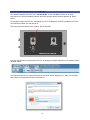
To configure the N-WAP simply copy its shown IP address and put it into the browser window of your
internet search program (ie. Windows Explorer, etc.) and press Enter. You should then see the logon
screen for the N-WAP and be able to logon using the default “admin” user name and “admin” password.
-C-
Appendix D Manual logon to DA1101 for configuration
The default IP address of the DA1101 is 192.168.40.253. It uses this address if there is no router
connected to it to give it an address (through the DHCP process) and/or someone presses its “Reset”
button.
To manually configure the DA1101, first change your PC’s IP address from DHCP provided to one in the
192.168.40.xxx subnet, like 192.168.40.10.
Then connect the PC directly to the “Data In” jack on the POE.
Use your web browser to connect to the DA1101, by putting its default IP address in your browser window
as shown below.
You should see the DA1101 logon screen pop up, as shown below. Simply type in “admin” for the logon
and “admin” for the password to logon to the DA1101.
-D-
Appendix E DA1101 Mounting Information & Best Practices
NOTE TO USE THE CIRCULAR COVER PREWIRE WITH A THREE GANG PLASTIC BOX.
The Pass and Seymour Slater S354RACS is recommended
For the Single Gang Wall Cover the Pass and Seymour Slater S122RS is recommended.
In all cases the back box should be of a RF friendly construction. (IE. Not Metal)
THE FOLLOWING WILL NOT WORK TOGETHER…..
-E-