1
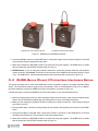
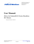
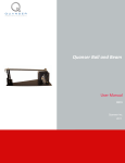
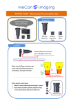
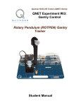
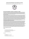
USER MANUAL
QUBE-Servo Experiment
Set Up and Configuration
Captivate. Motivate. Graduate.
© 2014 Quanser Inc., All rights reserved.
Quanser Inc.
119 Spy Court
Markham, Ontario
L3R 5H6
Canada
[email protected]
Phone: 1-905-940-3575
Fax: 1-905-940-3576
Printed in Markham, Ontario.
For more information on the solutions Quanser Inc. offers, please visit the web site at:
http://www.quanser.com
This document and the software described in it are provided subject to a license agreement. Neither the software nor this document may be
used or copied except as specified under the terms of that license agreement. All rights are reserved and no part may be reproduced, stored in
a retrieval system or transmitted in any form or by any means, electronic, mechanical, photocopying, recording, or otherwise, without the prior
written permission of Quanser Inc.
FCC Notice This device complies with Part 15 of the FCC rules. Operation is subject to the following two conditions: (1) this device may not
cause harmful interference, and (2) this device must accept any interference received, including interference that may cause undesired operation.
Industry Canada Notice This Class A digital apparatus complies with Canadian ICES-003. Cet appareil numérique de la classe A est conforme
à la norme NMB-003 du Canada.
Japan VCCI Notice This is a Class A product based on the standard of the Voluntary Control Council for Interference (VCCI). If this equipment
is used in a domestic environment, radio interference may occur, in which case the user may be required to take corrective actions.
Korea Communications Comission (KCC) Notice This equipment is Industrial (Class A) electromagnetic wave suitability equipment and seller
or user should take notice of it, and this equipment is to be used in the places except for home.
이 기기는 업무용(A급) 전자파적합기기로서 판
매자 또는 사용자는 이 점을 주의하시기 바라
며, 가정외의 지역에서 사용하는 것을 목적으로
합니다.
Waste Electrical and Electronic Equipment (WEEE)
This symbol indicates that waste products must be disposed of separately from municipal household waste, according to Directive
2002/96/EC of the European Parliament and the Council on waste electrical and electronic equipment (WEEE). All products at the
end of their life cycle must be sent to a WEEE collection and recycling center. Proper WEEE disposal reduces the environmental
impact and the risk to human health due to potentially hazardous substances used in such equipment. Your cooperation in proper
WEEE disposal will contribute to the effective usage of natural resources. For information about the available collection and
recycling scheme in a particular country, go to ni.com/citizenship/weee.
This product meets the essential requirements of applicable European Directives as follows:
• 2006/95/EC; Low-Voltage Directive (safety)
• 2004/108/EC; Electromagnetic Compatibility Directive (EMC)
Warning: This is a Class A product. In a domestic environment this product may cause radio interference, in
which case the user may be required to take adequate measures
QUBE-SERVO User Manual
2
CONTENTS
1
Presentation
4
2
System Hardware
2.1
System Schematic
2.2
Hardware Components
2.3
System Parameters
5
5
6
9
3
System Setup
3.1
Components
3.2
QUBE-Servo USB Interface Hardware Setup
3.3
QUBE-Servo myRIO Interface Hardware Setup
3.4
QUBE-Servo Direct I/O Interface Hardware Setup
QUBE-SERVO User Manual
10
10
10
10
11
v 1.1
1
PRESENTATION
The Quanser QUBE-Servo, pictured in Figure 1.1, is a compact rotary servo system that can be used to perform
a variety of classic servo control and inverted pendulum based experiments. The QUBE-Servo comes in three
versions: the USB Interface, Direct I/O Interface, and NI myRIO Interface. The QUBE-Servo USB Interface has
its own built-in power amplifier and data acquisition device. The QUBE-Servo Direct I/O Interface also has an
integrated amplifier but allows an external data acquisition (DAQ) device to interface to its I/O. The QUBE-Servo
myRIO Interface also has a built in amplifier, and allows a direct connection to the NI myRIO Expansion Port (MXP)
connector.
For all versions, the system is driven using a direct-drive 18V brushed DC motor housed in a solid aluminum frame.
Two add-on modules are supplied with the system: an inertial disc and a rotary pendulum. The modules can be
easily attached or interchanged using magnets mounted on the QUBE-Servo module connector. Single-ended
rotary encoders are used to measure the angular position of the DC motor and pendulum.
Main QUBE-Servo features:
• Compact and complete rotary servo system
• 18V direct-drive brushed DC motor
• Encoders mounted on DC motor and pendulum
• Built-in PWM amplifier
• Built-in USB data acquisition (DAQ) device (only for QUBE-Servo USB Interface)
• Inertial disc module
• Rotary pendulum module
Figure 1.1: Quanser QUBE-Servo
Caution: This equipment is designed to be used for educational and research purposes and is not
intended for use by the general public. The user is responsible to ensure that the equipment
will be used by technically qualified personnel only.
QUBE-SERVO User Manual
4
2
SYSTEM HARDWARE
2.1 System Schematic
There are three QUBE-Servo models with different I/O interface options: the QUBE-Servo USB Interface, the QUBEServo Direct I/O Interface, and the QUBE-Servo myRIO Interface. The QUBE-Servo USB Interface provides a
built-in data acquisition device and an integrated amplifier. The QUBE-Servo Direct I/O Interface and QUBE-Servo
myRIO Interface both have an amplifier but do not have built-in DAQ systems. Instead, the QUBE-Servo Direct I/O
Interface includes amplifier command and encoder ports that can be interfaced with an external DAQ device, and
the QUBE-Servo myRIO Interface includes an MXP connector to interface directly with the NI myRIO.
The interaction between the different system components on the QUBE-Servo is illustrated in Figure 2.1. On the
data acquisition (DAQ) device block, the motor and pendulum encoders are connected to the Encoder Input (EI)
channels #0 and #1. The Analog Output (AO) channel is connected to the power amplifier command, which then
drives the DC motor. The DAQ is interfaced to the PC or laptop via USB link in the QUBE-Servo USB Interface. In
the QUBE-Servo Direct I/O Interface and QUBE-Servo myRIO Interface systems, an external DAQ would be used
to interface to the amplifier and encoders.
Figure 2.1: Interaction between QUBE-Servo components.
The schematic given in Figure 2.2 illustrates the main QUBE-Servo components and how they interact with a data
acquisition (DAQ) device.
QUBE-SERVO User Manual
v 1.1
Figure 2.2: System schematic
2.2 Hardware Components
The main QUBE-Servo components - for the USB, Direct I/O, and NI myRIO interfaces - are listed in Table 2.1. The
components on the QUBE-Servo USB Interface are labeled in Figure 2.3a, the components on the QUBE-Servo
Direct I/O Interface are shown in Figure 2.3b, and the components on the QUBE-Servo myRIO Interface are in
Figure 2.3c.
ESD Warning: The internal components are sensitive to electrostatic discharge. Before handling the
QUBE-Servo, make sure you touch something metal to ground yourself.
ID
1
2
3
4
5
6
7
8
9
10
Component
Aluminum chassis
Module connector
Module connector magnets
USB DAQ connector†
Module encoder connector
Power connector
Power LED
Inertial disc
Pendulum link
Rotary arm rod
ID
11
12
13
14
15
16
17
18
19
20
Component
Rotary arm hub
Rotary pendulum magnets
Pendulum encoder
DC motor
Motor encoder
QUBE-Servo DAQ/amplifier board
Encoder 0 connector*
Encoder 1 connector*
Amplifier Input 0 connector*
NI myRIO MXP connector‡
Table 2.1: QUBE-Servo Components
‡ only on QUBE-Servo myRIO Interface
† only on QUBE-Servo USB Interface
*only on QUBE-Servo Direct I/O Interface
QUBE-SERVO User Manual
6
(a) QUBE-Servo USB Interface
(c) QUBE-Servo myRIO Interface
(e) QUBE-Servo Top View
(b) QUBE-Servo Direct I/O Interface
(d) QUBE-Servo Modules
(f) QUBE-Servo Interior
Figure 2.3: QUBE-Servo components
QUBE-SERVO User Manual
v 1.1
2.2.1 DC Motor
The QUBE-Servo includes a direct-drive 18V brushed DC motor housed in a solid aluminum frame. The motor
specifications are given in Table 2.2.
The QUBE incorporates an Allied Motion CL40 Series Coreless DC Motor model 16705. The complete specification
sheet of the motor is included at: http://alliedmotion.com/Products/Series.aspx?s=29.
Caution: Input ±10 V, 2 A peak, 0.5 A continuous.
Caution: Exposed moving parts.
Caution: Holding the motor in a stalled position for a prolonged period of time at applied voltages of over 5V
can result in permanent damage.
2.2.2 Encoder
The encoders used to measure the angular position of the DC motor and pendulum on the QUBE-Servo is a singleended optical shaft encoder. It outputs 2048 counts per revolution in quadrature mode (512 lines per revolution).
The encoders used to measure the angular position of the DC motor and pendulum on the QUBE is the US Digital
E8P-512-118 single-ended optical shaft encoder. The complete specification sheet of the E8P optical shaft encoder
is given in E8P Data Sheet.
2.2.3 Data Acquisition (DAQ) Device
The QUBE-Servo USB Interface circuit board includes a USB data acquisition device with two 16-bit encoder channels with quadrature decoding and two PWM output channels. The DAQ is very similar to the Quanser Q2-USB
board. See the Q2-USB User Manual [1] for more information. The QUBE-Servo Direct I/O Interface circuit board
does not have the built-in USB DAQ (it does have the amplifier and encoder channels).
2.2.4 Power Amplifier
The QUBE-Servo circuit board includes a PWM voltage-controlled power amplifier capable to providing 2 A peak
current and 0.5 A continuous current (based on the thermal current rating of the motor). The output voltage range
to the load is between ±10 V.
2.2.5 Amplifier Input Connector
The Amplifier Input RCA connector on the QUBE-Servo Direct I/O Interface is shown in Figure 2.3b. It is singleended and has a range of ±10V. As shown in Figure 2.2, it is connected to the amplifier command which then drives
the motor.
2.2.6 Encoder Connector
The Encoder 0 and Encoder 1 5-pin DIN connectors pictured on the QUBE-Servo Direct I/O Interface in Figure 2.3b
output the measurements from the motor encoder and the add-on module (e.g., pendulum) encoder, respectively.
The encoder connector pin-out is shown in Figure 2.4.
QUBE-SERVO User Manual
8
Figure 2.4: 5-pin DIN encoder pin-out
2.2.7 MXP Connector
The myRIO Connector A/B connector pictured on the QUBE-Servo myRIO Interface in Figure 2.3c is used to connect
the amplifier command line, and encoder readings from the QUBE-Servo components to either of the two NI myRIO
MXP connectors.
2.3 System Parameters
Table 2.2 lists and characterizes the main parameters associated with the QUBE-Servo.
Symbol Description
DC Motor
Vnom
Nominal input voltage
τnom
Nominal torque
ωnom
Nominal speed
Inom
Nominal current
Rm
Terminal resistance
kt
Torque constant
km
Motor back-emf constant
Jm
Rotor inertia
Lm
Rotor inductance
mh
Module attachment hub mass
rh
Module attachment hub radius
Jh
Module attachment moment of inertia
Inertia Disc Module
md
Disc mass
rd
Disc radius
Rotary Pendulum Module
mr
Rotary arm mass
Lr
Rotary arm length (pivot to end of metal rod)
mp
Pendulum link mass
Lp
Pendulum link length
Motor and Pendulum Encoders
Encoder line count
Encoder line count in quadrature
Encoder resolution (in quadrature)
Amplifier
Amplifier type
Peak Current
Continuous Current
Output voltage range
Value
18.0 V
22.0 mN-m
3050 RPM
0.540 A
8.4 Ω
0.042 N-m/A
0.042 V/(rad/s)
4.0 × 10⁻⁶ kg-m2
1.16 mH
0.016 kg
0.0111 m
0.6 × 10⁻⁶ kg-m2
0.053 kg
0.0248 m
0.095 kg
0.085 m
0.024 kg
0.129 m
512 lines/rev
2048 lines/rev
0.176 deg/count
PWM
2A
0.5 A
±10 V
Table 2.2: QUBE-Servo System Parameters
QUBE-SERVO User Manual
v 1.1
3
SYSTEM SETUP
Caution: If the equipment is used in a manner not specified by the manufacturer, the protection provided by the equipment may be impaired.
3.1 Components
To setup the QUBE-Servo system, you need the following components:
1. QUBE-Servo (USB, Direct I/O, or NI myRIO version; USB version shown in Figure 1.1)
2. Inertial disc module (shown in Figure 1.1)
3. Rotary Pendulum (ROTPEN) module (shown in Figure 1.1)
4. 15V 2.0 A power supply
Note: Only the power supply provided should be used with the QUBE-Servo
5. Power cable
6. USB 2.0 A/B cable, an RCA cable and two 5-pin-DIN cables, or NI myRIO MXP interface cable provided with
your QUBE-Servo depending on the version.
3.2 QUBE-Servo USB Interface Hardware Setup
To setup the QUBE-Servo USB Interface follow these steps:
1. Connect USB 2.0 cable from back cover of QUBE-Servo to an enabled USB 2.0 port on your desktop PC or
laptop.
2. The QUBE-Servo USB Interface driver should install automatically. If not, then you may not have installed all
the required software to support the device including either QUARCr or Quanser Rapid Control Prototyping
Toolkitr .
3. Connect the Power connector on the QUBE-Servo to the power supply. Ensure the power supply is connected
to a wall outlet using the appropriate power cable.
4. Attach the inertial disc or ROTPEN module to the motor hub using the magnets. The QUBE-Servo is shown
with the inertial disc and ROTPEN modules setup in Figure 3.1.
5. ROTPEN Users: If you are using the pendulum attachment, connect the encoder cable from the pendulum
module encoder to the Encoder 1 connector on the top panel of the QUBE-Servo(connector shown in Figure
2.3e). The QUBE-Servo with the attached pendulum and connected cable is pictured in Figure 3.1b.
3.3 QUBE-Servo myRIO Interface Hardware Setup
To setup the QUBE-Servo myRIO Interface follow these steps:
1. Connect NI myRIO MXP interface cable from the back cover of QUBE-Servo to either of the two MXP connectors (A or B) on the NI myRIO.
QUBE-SERVO User Manual
10
(a) QUBE-Servo with Inertial Disc Module
(b) QUBE-Servowith Pendulum Module
Figure 3.1: QUBE-Servo with different modules
2. Connect the Power connector on the QUBE-Servo to the power supply. Ensure the power supply is connected
to a wall outlet using the appropriate power cable.
3. Attach the inertial disc or ROTPEN module to the motor hub using the magnets. The QUBE-Servo is shown
with the inertial disc and ROTPEN modules setup in Figure 3.1.
4. ROTPEN Users: If you are using the pendulum attachment, connect the encoder cable from the pendulum
module encoder to the Encoder 1 connector on the top panel of the QUBE-Servo(connector shown in Figure
2.3e). The QUBE-Servo with the attached pendulum and connected cable is pictured in Figure 3.1b.
3.4 QUBE-Servo Direct I/O Interface Hardware Setup
This section describes how to connect the QUBE-Servo Direct I/O Interface system to your data acquisition (DAQ)
device. The connection procedure is given below, summarized in Table 3.1 and illustrated in Figure 3.2. In addition,
the cables needed to connect the QUBE-Servo Direct I/O Interface are shown in Figure 3.3.
Follow these steps to connect the QUBE-Servo Direct I/O Interface to your data acquisition device:
1. Before proceeding make sure your data acquisition (DAQ) device has been setup and successfully tested.
Refer to the documentation supplied with your DAQ system for set up and testing instructions.
2. Make sure the everything is powered off before making any of these connections. This includes turning off
your DAQ or your PC.
3. Using the RCA cable, connect the Analog Output #0 on the DAQ to the Amplifier Input 0 socket on the QUBEServo.
4. Using the 5-pin-DIN to 5-pin-DIN cable, connect the Encoder 0 connector on the QUBE-Servo to Encoder
Input #0 on the DAQ device. This carries the motor angle measurement.
5. Attach the inertial disc or ROTPEN module to the motor hub using the magnets. The QUBE-Servo is shown
with the inertial disc and ROTPEN modules setup in Figure 3.1.
QUBE-SERVO User Manual
v 1.1
Figure 3.2: Connections between QUBE-Servo Direct I/O Interface and an external DAQ
6. ROTPEN Users: If you are using the pendulum attachment, connect the encoder cable from the pendulum
module encoder to the Encoder 1 connector on the top panel of the QUBE-Servo (connector shown in Figure
2.3e). The QUBE-Servo with the attached pendulum and connected cable is pictured in Figure 3.1b.
7. ROTPEN Users: Using the 5-pin-DIN to 5-pin-DIN cable, connect the Encoder 1 connector on the QUBEServo to Encoder Input #1 on the DAQ device.
Cable #
1
From
DAQ: Analog Output #0
2
DAQ: Encoder Input #0
3
DAQ: Encoder Input #1
To
QUBE-Servo Amplifier Input
#0 connector
QUBE-Servo Encoder #0 connector
QUBE-Servo Encoder #1 connector
Signal
Amplifier voltage command driving motor.
Motor encoder measurement.
Pendulum module
measurement.
encoder
Table 3.1: QUBE-Servo wiring summary
(a) Amplifier Input Cable: RCA to RCA
(b) Encoder Cable: 5-pin-DIN to 5-pin-DIN
Figure 3.3: Cables used to connect QUBE-Servo Direct I/O Interface to a DAQ device
QUBE-SERVO User Manual
12
REFERENCES
[1] Quanser Inc. Q2-USB Data-Acquisition System User's Guide, 2010.
QUBE-SERVO User Manual
v 1.1
You Can Rely On Quanser
To Advance Control Education
For over two decades Quanser has focused solely on the development of
solutions for advanced control education and research. Today, over 2,500
University of Manchester • California Institute of Technology
Polytechnic School of Lausanne • Hong Kong University of Science
and Technology
universities,
colleges and research institutions around the world rely on a
University of Waterloo • Carnegie Mellon University
growing portfolio of Quanser control systems.
University of Toronto • Monash University • Kyoto University
University of Melbourne • ETH Zurich • Yale University
Our Rotary Control solutions offer quality, convenience, ease of use,
ongoing technical support and affordability. They are part of a wider range
f Alberta • Gifu University • Loughborough University
University of California, Berkeley • KTH • McMaster University of Quanser control lab solutions designed to enhance students’ academic
University Munich • Rice University • Kyoto Institute of Technology
experience. They come as complete workstations and can captivate
University of Auckland • MIT • Imperial College London
undergraduate and graduate students, motivate them to study further
he Chinese University of Hong Kong • Virginia Tech
and encourage them to innovate.
University of Houston • KAIST • Karlsruhe University
f Cincinnati • McGill University • Australian National University
Engineering educators worldwide agree that Quanser workstations are
reliable and robust. Choose from a variety of mechatronics experiments
ing Soud University • I.I.T Kharagpur •Memorial University
University of British Columbia • Delft University of Technology and control design tools appropriate for teaching at all levels as well as
University of Texas at Austin • Beijing Institute of Technology advanced research. Take advantage of engineering expertise that includes
f Tokyo • Princeton University • Hebei University of Technologymechatronics, electronics, software development and control system design.
University of Wisconsin-Madison • Holon Institute of TechnologyLeverage the accompanying ABET-aligned courseware which have been
of Klagenfurt • Harvard University • Tokyo Institute of Technology
developed to the highest academic standards. Last but not least, rely on
University of Reading • Tsinghua University • Cornell University Quanser’s engineers for ongoing technical support as your teaching or
University of Michigan • Korea University • Queen’s University research requirements evolve over time.
University of Bristol • Purdue University • Osaka University
University of Stuttgart • Georgia Tech • Ben-Gurion University
University Eindhoven • Ajou University • Kobe University
University of Maryland College Park • Nanyang Technological University
University of New South Wales • Washington University in St.Louis
National University of Singapore • Harbin Institute of TechnologyLearn more at www.quanser.com or contact us at [email protected]
University of Victoria • Boston University • Donghua University
Northwestern University • Tongji University • Royal Military College
Follow us on:
University of Quebec • Clemson University • Fukuoka University
Adelaide University • University of Barcelona • SUNY
Queen’s University Belfast •Istanbul Technical University
ABET, Inc., is the recognized accreditor for college and university programs in applied science, computing, engineering,
e Los Andes • Louisiana Tech • Norwegian University of Science
and Technology
and technology. Among the most respected accreditation organizations in the U.S., ABET has provided leadership and
quality assurance in higher education for over 75 years.
United States Military Academy • CINVESTAV • Drexel University
LabVIEW™ is a trademark of the National Instruments.
[email protected]
Products and/or services pictured and referred to herein and their accompanying specifications may be subject to
change without notice. Products and/or services mentioned herein are trademarks or registered trademarks of
Quanser Inc. and/or its affiliates. LabVIEW™ is a trademark of the National Instruments. Windows® is a trademark of
the Microsoft. Other product and company names mentioned herein are trademarks or registered trademarks
of their respective owners. ©2014 Quanser Inc. All rights reserved.
v2.3
+1-905-940-3575
Solutions for teaching and research. Made in Canada.
QUANSER.COM