1
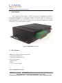
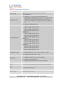
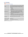
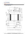
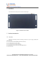
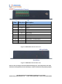
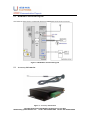
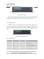
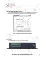
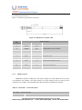
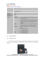
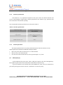
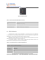
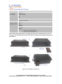
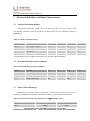
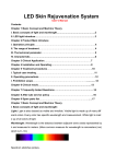
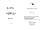
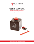
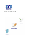
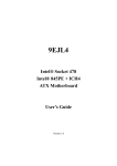
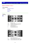
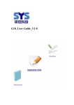
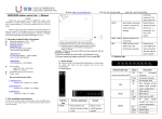
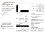
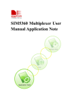
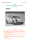
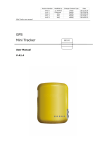
HDM1003G_User Guide V1.03 Copyright © Shenzhen Head Weblink Technology CO,. Ltd. 2014 Website:http://www.headele.com Tel No. +86-755-86111909 Fax No. +86-755-86111900 Document Title HDM1003G User Guide Version V1.03 Date 2014-11-01 Status Release Document Control ID HDM1003G_User Guide_V1.03 General Notes. Shenzhen Weblink Technology CO,. Ltd offers this information as a service to its customers, to support application and engineering efforts that use the products designed by Shenzhen Weblink Technology CO,. Ltd. The information provided is based upon requirements specifically provided to Shenzhen Weblink Technology CO,. Ltd by the customers. Shenzhen Weblink Technology CO,. Ltd has not undertaken any independent search for additional relevant information, including any information that may be in the customer’s possession. Furthermore, system validation of this product designed by Shenzhen Weblink Technology CO,. Ltd within a larger electronic system remains the responsibility of the customer or the customer’s system integrator. All specifications supplied herein are subject to change. Copyright © Shenzhen Head Weblink Technology CO,. Ltd. 2014 Website:http://www.headele.com Tel No. +86-755-86111909 Fax No. +86-755-86111900 Version History Date Version Description of change Author 2012-05-3 1.00 Origin Jianhua Liu 2012-08-15 1.01 §6.3 Correct the PIN assignment Zhenrong Qu 2013-05-22 1.02 §6.3 Correct the signal assignment Jianhua Liu 2014-11-01 1.03 1.Modify interface connector 2.Modify voltage input level Jianhua Liu Copyright © Shenzhen Head Weblink Technology CO,. Ltd. 2014 Website:http://www.headele.com Tel No. +86-755-86111909 Fax No. +86-755-86111900 1 Introduction This document describes features, functions and interfaces of HDM1003G terminal in great detail. HDM1003G is a dual-band WCDMA modem that works on frequencies of WCDMA(850/1900MHz or 900/2100MHz). which is a ideal solution for wireless m2m applications.With the help of this document user can understand HDM1003G interface specifications, electrical and mechanical quickly. Figure 1: HDM1003G overview 2 Key features HDM1003G terminal has the following features: 1. Standard AT commands set 2. USB, RS232 or RS485 interface. 3. Watch-dog function 4. ESD protection 5. GPIOs 6. +5V~+30V Power supply Table 1: HDM1003 key features Feature Implementation Copyright © Shenzhen Head Weblink Technology CO,. Ltd. 2014 Website:http://www.headele.com Tel No. +86-755-86111909 Fax No. +86-755-86111900 Power supply 5V ~ 30V Power saving Typical power consumption in sleep mode is 70mW ( BS-PA-MFRMS=9 ) Frequency bands HDM1003G dual-band:WCDMA 850/1900MHz or 900/2100MHz. HDM1003G can search the frequency bands automatically. The frequency bands also can be set by AT command “AT+CBAND”. For details, please refer to document [1]. Compliant to GSM Phase 2/2+ Transmitting power WCDMA 2100 @Power 23dBm Typical 460 mA @Power 21dBm Typical 410 mA @Power 10dBm Typical 245 mA WCDMA 1900 @Power 23dBm Typical 445 mA @Power 21dBm Typical 400 mA @Power 10dBm Typical 235 mA WCDMA 900 @Power 23dBm Typical 400 mA @Power 21dBm Typical 355 mA @Power 10dBm Typical 230 mA WCDMA 850 @Power 23dBm Typical 390 mA @Power 21dBm Typical 346 mA @Power 10dBm Typical 227 mA Temperature range Normal operation: -30°C ~ +70°C Restricted operation: -40°C ~ -30°C and +80 °C ~ +85°C* Storage temperature -45°C ~ +90°C Data GPRS WCDMA data downlink transfer: max. 14.4Mbps WCDMA data uplink transfer: max.5.76Mbps Integrate the TCP/IP protocol. Support Packet Broadcast Control Channel (PBCCH) CSD Support CSD transmission USSD Unstructured Supplementary Services Data (USSD) support SMS MT, MO, CB, Text and PDU mode SMS storage: SIM card FAX Group 3 Class 1 SIM interface Support SIM card: 1.8V, 3V External antenna SMA type RF connector Copyright © Shenzhen Head Weblink Technology CO,. Ltd. 2014 Website:http://www.headele.com Tel No. +86-755-86111909 Fax No. +86-755-86111900 USB port This interface is compliant with the USB2.0 specification. The USB2.0 specification requires hosts such as the computer to support all three USB speeds, namely low-speed (1.5Mbps), full-speed (12Mbps) and high-speed (480Mbps). USB charging and USB-OTG is not supported. RS232 serial port Serial port: Full modem interface with status and control lines, unbalanced, asynchronous. supports the baud rate:300, 600, 1200, 2400, 4800, 9600, 19200, 38400, 57600, 115200, 230400, 460800, 921600, 3200000, 3686400, 4000000bps. Default rate is 115200bps.. Can be used for AT commands data stream. Support RTS/CTS hardware handshake and software ON/OFF flow control. Multiplex ability according to GSM 07.10 Multiplexer Protocol. Autobauding supports baud rate from 1200 bps to 57600bps. Phonebook management Support phonebook types: SM, FD, LD, RC, ON, MC. SIM application toolkit GSM 11.14 Release 99 Physical characteristics Size: 116*59*23mm Weight: 110g Firmware upgrade Firmware upgradeable by USB interface * HDM1003G does work at this temperature, but some radio frequency characteristics may deviate from the wcdma specification. Copyright © Shenzhen Head Weblink Technology CO,. Ltd. 2014 Website:http://www.headele.com Tel No. +86-755-86111909 Fax No. +86-755-86111900 3 Terminal dimensions Figure 2: Mechanical dimensions of HDM1003G(Unit: mm) Copyright © Shenzhen Head Weblink Technology CO,. Ltd. 2014 Website:http://www.headele.com Tel No. +86-755-86111909 Fax No. +86-755-86111900 4 Installation The terminal can be fixed by four screw holes as follow figure. Figure 3: Installation of the terminal 5 5.1 Interface introduction Overview HDM1003G Terminal provides the following connectors for power supply, GPIOs,Serial port and antenna: The 3G antenna interface(SMA type female connector) The 2 PIN I/O port for power supply The 10 PIN I/O port for GPIOs and RS232 LED indicator for power (Red) and GSM Netlight (Green) SIM card holder Copyright © Shenzhen Head Weblink Technology CO,. Ltd. 2014 Website:http://www.headele.com Tel No. +86-755-86111909 Fax No. +86-755-86111900 Pins 1 2 3 4 5 6 7 8 9 10 11 12 Direction Description I I/O I/O I/O O I O O I O I Power supply. +5V~+30V GND GPIO4 GPIO3 GPIO2 UART Ring UART RTS UART CTS UART TXD or RS485 TXD UART RXD or RX485 RXD UART DCD UART DTR Figure 4: HDM1003G interface Front view Figure 5: HDM1003G interface Back view Note: For the I/O interface, Shenzhen Weblink Technology CO,. Ltd could provide 2-line cable and 10-line cable (optional) to assist developers; it will be introduced at the following chapter. Copyright © Shenzhen Head Weblink Technology CO,. Ltd. 2014 Website:http://www.headele.com Tel No. +86-755-86111909 Fax No. +86-755-86111900 5.2 HDM1003G Functional Diagram The following figure shows a functional diagram of HDM1003G and typical accessories. Figure 6: HDM1003G functional diagram 5.3 Accessory information Figure 7: Accessory information Copyright © Shenzhen Head Weblink Technology CO,. Ltd. 2014 Website:http://www.headele.com Tel No. +86-755-86111909 Fax No. +86-755-86111900 A: HDM1003G Terminal B: GSM Antenna 6 6.1 Application Interface Power Supply Customer can use the DC adapter that Shenzhen Weblink Technology CO,. Ltd provides as the power source. If customer does not use the adapter, then DC source should be satisfied with the following requirements. Input voltage range +5V~+30V Normal voltage 12V Current ability 1A Table 2: The consumption in sleep mode HDM1003G @5V @12V @15V Sleep current 14.5mA 7.75mA 5.02mA The following chapter introduces the power line that Shenzhen Weblink Technology CO,. Ltd provides to customers, customer can power the terminal by connect the terminal to the DC source via this line. The power line includes four lines as the following figure shows, and table 3 gives a detailed description. Table 3: The power line assignment PIN Number Colour Item 1 Red +5~+30V 2 Black GND Figure 8: dimensions of power line(Unit: mm) Copyright © Shenzhen Head Weblink Technology CO,. Ltd. 2014 Website:http://www.headele.com Tel No. +86-755-86111909 Fax No. +86-755-86111900 Figure 9: Power interface When a valid power appears the terminal will power up automatic, for the MCU that inside the terminal processed the power up part, MCU also acts as a Watch Dog, when the terminal runs wrong, MCU will cut off the power and recover it immediately to restart the terminal. 6.2 Serial Interface HDM1003G provides one asynchronous RS232 serial port.The RS232 standard interface serves to connect a PC, Data Terminal Equipment (DTE) or other application, which acts as host controller of the HDM1003G Terminal with all its functions. Through the USB or RS232 interface it can be used as WCDMA modem for sending and receiving of SMS, Data and Fax calls. Figure 10: Pin assignment RS-232 Table 4: RS-232 Connector Pin no Signal name I/O Function 6 RING O Ring indicator 7 RTS I Request To Send 8 CTS O Clear to send 9 TXD O Transmit Data (RS485 TXD) 10 RXD I Receive Data (RS485 RXD) 11 DCD O Data Carrier Detected 12 DTR I Data Terminal Ready Note: HDM1003G supports autobauding, Autobauding allows HDM1003G to automatically Copyright © Shenzhen Head Weblink Technology CO,. Ltd. 2014 Website:http://www.headele.com Tel No. +86-755-86111909 Fax No. +86-755-86111900 detect the baud rate of the host device. User can use AT command “AT+IPR=x” to set a fixed baud rate and the setting will be saved to non-volatile flash memory automatically. After the configuration is set as fixed baud rate, the URC such as "RDY", "+CFUN: 1" and "+CPIN: READY” will be reported when HDM1003G is powered on. Hyper terminal usually as the PC software tool to operate HDM1003G; customer can set up a connection between PC and terminal, configure the port properties as the figure 9 shows. Figure 11: COM port properties of the hyper terminal 6.3 10 PIN I/O interface HDM1003G provides a 10 PIN I/O interface for customer use, including GPIOs and RS232 channel. The following figure gives a brief view of signal assignment. Figure 12: signal assignment of 10PIN I/O port To make the usage conveniently, Shenzhen Weblink Technology CO,. Ltd provides a cable Copyright © Shenzhen Head Weblink Technology CO,. Ltd. 2014 Website:http://www.headele.com Tel No. +86-755-86111909 Fax No. +86-755-86111900 for customer, it can be inserted to the 10 PIN I/O port so customer can develop their application by connecting some devices. Figure 13 shows the specification of the cable. Figure 13: Dimensions of 10-line cable P1 6.3.1 Terminal signal Signal name I/O Comments 3 GPIO4 I/O 4 GPIO3 I/O 5 GPIO2 I/O 6 RING O RING Indicator 7 RTS I Request to send 8 CTS O Clear to send 9 TXD O Transmit Data (RS485 TXD) 10 RXD I Recieve Data (RS485 TXD) 11 DCD O Data Carrier Detected 12 DTR I Data Terminal Ready Configurable by AT commands GPIO interfaces HDM1003G provides 4 GPIO pins. The output voltage level of the GPIO can be set by the AT command “AT+ SGPIO”. The input voltage level of the GPIO can also be read by the AT command “AT+ SGPIO”. The following table shows the detail commands about GPIO. Table 5: AT+SGPIO Control the GPIO AT+ SGPIO Control the GPIO Test Command Response Copyright © Shenzhen Head Weblink Technology CO,. Ltd. 2014 Website:http://www.headele.com Tel No. +86-755-86111909 Fax No. +86-755-86111900 AT+SGPIO=? +SGPIO: (0-1),(1-12),(0-2),(0-1) OK Parameters See Write Command Write Command AT+SGPIO= <operation>,<GPI O>,<function> ,<level> Response OK ERROR Parameters <Operation> 0 1 <GPIO> <function> <level> 6.4 6.4.1 0 1 2 0 1 Set the GPIO function including the GPIO output and GPIO as the Keypad. Read the GPIO level. Please note that only when the gpio is set as input, user can use parameter 1 to read the GPIO level, otherwise the module will return "ERROR". The GPIO you want to be set. (It has relations with the hardware, please refer to the hardware manual) Only when <Operation> is set to 0, this option takes effect. Set the GPIO to input. Set the GPIO to output Set the GPIO to keypad Set the GPIO low level Set the GPIO high level Antenna interface Antenna connector Antenna connector allows transmission of radio frequency (RF) signals between the modem and the external supplied antenna. The HDM1003G modem is fitted with a 50Ω male SMA connector. Copyright © Shenzhen Head Weblink Technology CO,. Ltd. 2014 Website:http://www.headele.com Tel No. +86-755-86111909 Fax No. +86-755-86111900 Figure 14: Antenna interface 6.4.2 Antenna specifications The antenna is a very important component in the system. Since the antenna transmits and receives electromagnetic signal, and its efficiency depends on the antenna’s type, placement and the environment of the antenna operating. The recommended antenna specifications are showed in Table 12: Table 6: antenna specifications 6.4.3 Frequency range WCDMA 850/1900 or 900/2100MHz Impedance 50 ohm Input power > 33dBm (2W) peak power in WCDMA VSWR recommended ≤2:1 VSWR absolute max ≤10:1 Gain ≤3dBi Antenna placement The antenna performance is very easily influenced by other electronic devices. So the antenna placement should be considered carefully as follow. 1. Place away from other electronic devices or other antennas. 2. Place far away from metal material. 3. Face the base station antenna directly if the signal strength is very weak. 6.5 LED indicator A red led indicates the power status, when a valid power appears, the red led will lighten up. But a lighten up red led does not mean that the terminal has been powered up. A green led indicates the terminal status and WCDMA net status, after the terminal been powered up and registered to the network, it will blink at a certain frequency. Copyright © Shenzhen Head Weblink Technology CO,. Ltd. 2014 Website:http://www.headele.com Tel No. +86-755-86111909 Fax No. +86-755-86111900 Figure 15: Indicator LED Table 7: Status of the NETLIGHT indicator (Green) Status HDM1003G behavior Off HDM1003G is not running 64ms On/ 800ms Off HDM1003G not registered the network 64ms On/ 3000ms Off HDM1003G registered to the network 64ms On/ 300ms Off WCDMA communication is established 6.6 SIM Card Interface The SIM interface complies with the GSM Phase 1 specification and the new GSM Phase 2+ specification for FAST 64 kbps SIM card. Both 1.8V and 3.0V SIM card are supported. The SIM interface is powered from an internal regulator inside the terminal. HDM1003G supports SIM card “hot” plug, which means that the terminal can sense the SIM card inserted in or drawn out when the module is on AT command “AT+CSDT” is used to enable or disable SIM card detection function. For details of this AT command, please refer to the following table. Table 8: AT+CSDT Switch On or Off Detecting SIM Card AT+CSDT Switch On or Off Detecting SIM Card Test Command AT+CSDT =? Response +CSDT: (0-1) OK Parameter Copyright © Shenzhen Head Weblink Technology CO,. Ltd. 2014 Website:http://www.headele.com Tel No. +86-755-86111909 Fax No. +86-755-86111900 See Write Command Read Command AT+CSDT? Response +CSDT: <mode> OK Parameter See Write Command Write Command AT+CSDT=<mode > Response OK ERROR Parameter <mode> 0 Switch off detecting SIM card 1 Switch on detecting SIM card Note: when the detecting function is activated, the status of sim card will auto report via the serial port. The sensing of a hot removal of the SIM is not supported during power saving mode (AT+CFUN=4). Figure 16: Installation of SIM Card Copyright © Shenzhen Head Weblink Technology CO,. Ltd. 2014 Website:http://www.headele.com Tel No. +86-755-86111909 Fax No. +86-755-86111900 7 Electrical, Reliability and Radio Characteristics 7.1 Absolute Maximum Ratings The absolute maximum ratings stated in following table are stress ratings under non-operating conditions. Stresses beyond any of these limits will cause permanent damage to HDM1003G. Table 9: Absolute maximum ratings Symbol Parameter Min Typ Max Unit VBAT Power supply voltage 4.5 - 42 V Input voltage -0.3 - 3.1 V Input current - - 10 mA Output current - - 10 mA VI II * * IO* * These parameters are for digital interface pins, such as GPIO, UART and DEBUG. 7.2 Recommended Operating Conditions Table 10: Recommended operating conditions Symbol Parameter Min Typ Max Unit VBAT Power supply voltage 5 12 30 V TOPER Operating temperature -40 +25 +85 ℃ TSTG Storage temperature -45 +90 ℃ 7.3 Electro-Static Discharge HDM1003G is an ESD sensitive component, so more attention should be paid to the procedure of handling and packaging. The ESD test results are shown in the following table. Table 11: The ESD characteristics (Temperature: 25℃, Humidity: 45 %) Test item Shell Contact discharge Air discharge ±10KV ±15KV Copyright © Shenzhen Head Weblink Technology CO,. Ltd. 2014 Website:http://www.headele.com Tel No. +86-755-86111909 Fax No. +86-755-86111900 RF interface ±10KV ±15KV RS232 interface ±10KV ±15KV Audio interface ±10KV ±15KV SIM card holder ±10KV ±15KV 7.4 Operating frequency The operating frequencies in WCDMA 850/1900MHz or 900/2100MHz are conform to the WCDMA Specifications, shown as bellow. Table 12: Operating frequency Mode Freq. TX(MHz) Freq. RX(MHz) GSM-850 824 – 849 869 – 894 890-915 935-960 880-890 925 - 935 DCS-1800 1710-1785 1805-1880 PCS-1900 1850 - 1910 1930 - 1990 WCDMA 2100 2110~2170 2110~2170 WCDMA 1900 1930~1990 1850~1910 WCDMA 900 925 ~960 880 ~915 WCDMA 850 869 ~894 824 ~849 E-GSM-900 7.5 Transmitter output power and receiver sensitivity The HDM1003G’s conducted transmitter output power and receiver sensitivity are shown as bellow: Table 13: Transmitter output power and receiver sensitivity Frequency Max Min GSM850 33dBm ±2dB 5dBm ±5dB E-GSM900 33dBm ±2dB 5dBm ±5dB DCS1800 30dBm ±2dB 0dBm ±5dB PCS1900 30dBm ±2dB 0dBm ±5dB GSM850 (8-PSK) 27dBm ±3dB 5dBm ±5dB E-GSM900 (8-PSK) 27dBm ±3dB 5dBm ±5dB DCS1800 (8-PSK) 26dBm +3/-4dB 0dBm ±5dB Copyright © Shenzhen Head Weblink Technology CO,. Ltd. 2014 Website:http://www.headele.com Tel No. +86-755-86111909 Fax No. +86-755-86111900 PCS1900(8-PSK) 26dBm +3/-4dB 0dBm ±5dB WCDMA 2100 24dBm +1/-3dB -56dBm ±5dB WCDMA 1900 24dBm +1/-3dB -56dBm ±5dB WCDMA 850 24dBm +1/-3dB -56dBm ±5dB WCDMA 900 24dBm + 1/-3dB -56dBm ±5dB Appendix A. Related Documents Table 14: Related documents SN Document name Remark [1] SIM5360_AT Manual SIM5360 AT Command Manual [2] AN_SIM5360_TCPIP TCP/IP Applications User Manual [3] SIM5360_Multiplexer User Manual_Application Note SIM5360 Multiplexer User Manual Application Note [5] SIM5360_Embedded Application Note SIM5360 Embedded AT Application Note [6] AN_Serial Port Application Note About Serial Port [7] HDM1003G GPRS Setup User Guide HDM1003G GPRS Setup User Guide [8] ITU-T Draft new recommendation V.25ter: Serial asynchronous automatic dialing and control [9] GSM 07.07: Digital cellular telecommunications (Phase 2+); AT command set for GSM Mobile Equipment (ME) [10] GSM 07.10: Support GSM 07.10 multiplexing protocol [11] GSM 07.05: Digital cellular telecommunications (Phase 2+); Use of Data Terminal Equipment – Data Circuit terminating Equipment (DTE – DCE) interface for Short Message Service (SMS) and Cell Broadcast Service (CBS) [12] GSM 11.14: Digital cellular telecommunications system (Phase 2+); Specification of the SIM Application Toolkit for the Subscriber Identity Module – Mobile Equipment (SIM – ME) interface [13] GSM 11.11: Digital cellular telecommunications system (Phase 2+); Specification of the Subscriber Identity Module – Mobile Equipment (SIM – ME) interface Command AT Copyright © Shenzhen Head Weblink Technology CO,. Ltd. 2014 Website:http://www.headele.com Tel No. +86-755-86111909 Fax No. +86-755-86111900 [14] GSM 03.38: Digital cellular telecommunications system (Phase 2+); Alphabets and language-specific information [15] GSM 11.10 Digital cellular telecommunications system (Phase 2); Mobile Station (MS) conformance specification; Part 1: Conformance specification B. Terms and Abbreviations Table 15: Terms and Abbreviations Abbreviation Description ADC Analog-to-Digital Converter AMR Adaptive Multi-Rate AT Attention commands CS Coding Scheme CSD Circuit Switched Data CTS Clear to Send DTE Data Terminal Equipment (typically computer, terminal, printer) DTR Data Terminal Ready DTU Data Transmit Unit DTX Discontinuous Transmission EFR Enhanced Full Rate EGSM Enhanced GSM ESD Electrostatic Discharge ETS European Telecommunication Standard FR Full Rate GPRS General Packet Radio Service GSM Global Standard for Mobile Communications HR Half Rate IMEI International Mobile Equipment Identity Li-ion Lithium-Ion MO Mobile Originated MS Mobile Station (GSM engine), also referred to as TE MT Mobile Terminated NC NO Connect NA Not Access PAP Password Authentication Protocol PBCCH Packet Broadcast Control Channel Copyright © Shenzhen Head Weblink Technology CO,. Ltd. 2014 Website:http://www.headele.com Tel No. +86-755-86111909 Fax No. +86-755-86111900 PCB Printed Circuit Board PCL Power Control Level PCS Personal Communication System, also referred to as GSM 1900 PDU Protocol Data Unit PPP Point-to-point protocol RF Radio Frequency RMS Root Mean Square (value) RTC Real Time Clock RX Receive Direction SIM Subscriber Identification Module SMS Short Message Service TE Terminal Equipment, also referred to as DTE TX Transmit Direction UART Universal Asynchronous Receiver & Transmitter URC Unsolicited Result Code USSD Unstructured Supplementary Service Data Phonebook abbreviations FD SIM fix dialing phonebook LD SIM last dialing phonebook (list of numbers most recently dialed) MC Mobile Equipment list of unanswered MT calls (missed calls) ON SIM (or ME) own numbers (MSISDNs) list RC Mobile Equipment list of received calls SM SIM phonebook NC Not connect C. Safety Caution Table 16: Safety caution Marks Requirements When in a hospital or other health care facility, observe the restrictions about the use of mobiles. Switch the cellular terminal or mobile off, medical equipment may be sensitive to not operate normally for RF energy interference. Switch off the cellular terminal or mobile before boarding an aircraft. Make sure it is switched off. The operation of wireless appliances in an aircraft is forbidden to prevent interference with communication systems. Forget to think much of these instructions may lead to the flight safety or offend against local legal action, or both. Copyright © Shenzhen Head Weblink Technology CO,. Ltd. 2014 Website:http://www.headele.com Tel No. +86-755-86111909 Fax No. +86-755-86111900 Do not operate the cellular terminal or mobile in the presence of flammable gases or fumes. Switch off the cellular terminal when you are near petrol stations, fuel depots, chemical plants or where blasting operations are in progress. Operation of any electrical equipment in potentially explosive atmospheres can constitute a safety hazard. Your cellular terminal or mobile receives and transmits radio frequency energy while switched on. RF interference can occur if it is used close to TV sets, radios, computers or other electric equipment. Road safety comes first! Do not use a hand-held cellular terminal or mobile when driving a vehicle, unless it is securely mounted in a holder for hands free operation. Before making a call with a hand-held terminal or mobile, park the vehicle. WCDMA cellular terminals or mobiles operate over radio frequency signals and cellular networks and cannot be guaranteed to connect in all conditions, for example no mobile fee or a invalid SIM card. While you are in this condition and need emergent help, please remember using emergency calls. In order to make or receive calls, the cellular terminal or mobile must be switched on and in a service area with adequate cellular signal strength. Some networks do not allow for emergency call if certain network services or phone features are in use (e.g. lock functions, fixed dialing etc.). You may have to deactivate those features before you can make an emergency call. Also, some networks require that a valid SIM card be properly inserted in the cellular terminal or mobile. Contact us: Shenzhen Head Weblink Technology CO,. Ltd. Add: Rm.408,Building 5.Donghua Design house, Nanguang Rd. Shenzhen. PRC Tel: +86 -755-86111909 Fax: +86 -755-86111900 URL: Http://www.headele.com Copyright © Shenzhen Head Weblink Technology CO,. Ltd. 2014 Website:http://www.headele.com Tel No. +86-755-86111909 Fax No. +86-755-86111900