1
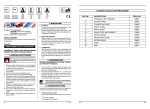
USER’S MANUAL
Ferm Belt Sander / Grinder
FBSM-150/50
Art.nr. 750350
Ferm b.v. • P.O. Box 134 • 8280 AC Genemuiden-NL • Web: www.ferm.com
0106/12
1'
230V~50Hz
240W
;;
No=2950/Min 686x50mm Ø150x20mm Ø 12.7 mm
Description
AVAILABLE ACCESSORIES FOR FBSM-150/50
REF.NR.
Fig. 1
Fig. 2
2
Fig. 3
DESCRIPTION
FERM NR.
1
PROTECTION GLASS
206401
4
SUPPORT LEFT
206152
5
RUBBER FOOT
206411
6
SWITCH
206451
9
FIXING KNOB
206157
11
SPRING
206158
15
ROTATION WHEEL
206156
16
DRIVING WHEEL
206155
18
PROTECTION GLASS HOLDER
206154
Fig. 4
Ferm
Ferm
7
GB
BEFORE YOU OPERATE THE MACHINE:
1. Make sure the switch is “OFF” before you plug in the
machine.
2. Keep the cable away from moving parts.
English
Product: Ferm Belt Sander / Grinder
Type FBSM-150/50, Art.nr. 750350
Ferm, Genemuiden, The Netherlands
Sound pressure level Lpa
!
76 dB(A)
In order to prevent overheating and possible damages to the engine, use the
machine for periods of 30 minutes
CAREFULLY READ THE INSTRUCTIONS BEFORE
YOU USE THE BELT SANDER/GRINDER!
1. ADDITIONAL SAFETY RULES
BEFORE USING THE MACHINE:
1. Check the following:
- Make sure that your machine is correct for your
power supply.
- Make sure the socket is earthed;
- Make sure the cable and socket are in good condition, i.e. not frayed or damaged.
2. Do not use long extension cables.
Use only earthed extension cables.
3. A grinding stone is fragile.
The stone is easily damaged when being dropped, hit,
etc. Always grind with the face of the grinding stone,
never the sides. A cracked grinding stone must be
replaced immediately. Due to the high rotational velocity the stone might disintegrate, causing accidents.
4. Always wear safety glasses when grinding.
5. Never operate the Belt Sander/Grinder without the
guard in place.
6. Make sure the guard and the tool rest are properly
adjusted and secured.
7. The maximum clearance between the tool rest and the
grinding stone must never exceed 1-1.5 mm.
8. Use the stone only for its intended purpose, e.g. for
grinding tools, never for heavy-duty construction
work.
Use only grinding stones that state the following:
- Name of the manufacturer;
- Binding material;
- Dimensions;
- Maximum speed.
9. Never rebore the arbor hole in the grinding stone to
widen the diameter.
10. The maximum admissable rotational velocity of the
grinding stone may not exceed the velocity mentioned
on the stone.
11. For safe grinding it is best to bolt the machine to the
bench.
6
Ferm
Ferm
IMMEDIATELY SWITCH OFF THE MACHINE WHEN:
1. plug and/or cable are defective or damaged;
2. the switch is defective;
3. you smell or see smoke caused by scorched insulation.
2. INSTALLATION
1. The Belt Sander/Grinder is fitted with a three-core
cable and earthed plug. Therefore, always connect
the plug to an earthed socket. If you have to use an
extension cable, make sure it is three-core and fitted
with an earthed plug and connector.
2. Do not use long extension cables.
3. The Belt Sander/Grinder has to be secured to the
bench by means of bolts. The length of the bolts
depends on the thickness of the bench. If your bench is
made of steel, it is best to place the machine on a supporting, wooden plate to separate it from the bench, to
avoid vibrations.
Electrical safety
Always check that the power supply corresponds to the
voltage on the rating plate.
Replacing cables or plugs
Immediately throw away old cables or plugs when they
have been replaced by new ones. It is dangerous to insert
the plug of a loose cable in the wall outlet.
Using extension cables
• The grinding machine is fitted with a three-core cable
and earthed plug. Therefore, always connect the plug
to an earthed socket. If you have to use an extension
cable, make sure it is three-core and fitted with an earthed plug and connector.
• The minimum conductor size is 1.5 mm2.
3. DESCRIPTION
THE NUMBERS BELOW REFER TO THE ILLUSTRATION ON PAGE 2:
DESCRIPTION:
1. Cover glass;
2. Guard for grinding stone;
3. Grinding stone;
4. Tool rest;
5. Bottom plate;
6. ON/OFF switch;
7. Sanding belt;
8. Guard for sanding belt;
9. Knurled knob for tension roller;
10. Adjustment screw for belt position;
11. Spring;
3
12. Tool rest;
13. Motor housing;
14. Second eye for tool rest;
15. Guide roll;
16. Drive roll;
18. Cover glass holder.
4. GRINDING
Grinding
- Do not ‘fil up’ the stone by holding wood, lead or any
other soft metal against the grinding stone;
- Never press the workpiece too hard against the stone,
to avoid making grooves;
- Cool down the workpiece with water;
- Wood chisels and such must never ‘blue’ when being
ground;
- Make sure the workpiece cannot slip from your fingers
during grinding and get caught between the tool rest
and the stone. This may cause the stone to crack, the
motor to stall and the workpiece to rebound, causing
injuries.
MOUNTING AND ADJUSTMENT OF THE HOLDERS
OF COVER GLASSES AND THE COVER GLASSES
THEMSELVES.
REPLACING THE GRINDING STONE
- Remove the tool rest (C) (see fig. 1) by removing bolt
(A) and nut (B).
- Remove the three screws (A) (see Description) which
fasten the guard (2) to the motor housing (13).
- Remove the guard (2).
- Loosen nut (A) (see fig. 2) with a spanner.
NOTE: This is a left handed nut.
- Remove the nut, the clamping disc (B) and the paper
spacer ring (C).
- Then remove the grinding stone (D).
- Also remove the other clamping disc and paper spacer
ring (E & F).
- Clean the shaft (G) with a cloth.
- Mount the new/other grinding stone.
!
-
Mount first the clamping disc and paper
spacer ring, then the grinding stone, next
the other paper spacer ring and clamping
disc and the left handed nut.
Retighten the nut firmly.
Place the guard back and retighten the guard with
screws (3x).
Place the tool rest and readjust the tool rest (see
Adjusting the tool rest).
5.SANDING
!
-
The holder of a cover glass, together
with the cover glasses themselves
will always be adjusted/mounted with
the grinding stone being out of action
and the currrent turned out.
- Mount the holder of the cover
glass together with the cover
glass itself, by means of the
screw (A).
- Adjust the height of the holder of the cover glass by loosening a bit screw . The free
space between the stone and
the holder of the cover glass
will amount to 1 - 1,5 mm.
- Fasten well screw.
Adjust the cover glass (see the figure above) in such a
way that your face will be protected, at the utmost.
Use always safety glasses at the same time you will be
working with the cover glass.
ADJUSTING THE TOOL REST
!
-
4
Disconnect the machine and make sure
the grinding stone has stopped before
adjusting the tool rest.
Loosen bolts (A) (see fig. 1).
Move the tool rest (C) keeping a clearance of 1-1.5 mm
between the tool rest and the grinding stone.
Retighten bolts (A).
THE CHOICE OF SANDING PAPER
- With coarse sanding paper (P 50) generally most of
the material can be removed, and fine sanding paper
(P120) is then used for finishing. The grain of the sanding paper is mentioned on the back of the paper.
- An uneven surface is first treated with coarse sanding
paper and sanded until it is even. Subsequently
medium-coarse sanding paper (P 80) is used to
remove the scratches caused by the first type of paper
used. Fine sanding paper (P 120) is used for finishing.
MOUNTING OF THE BELT SANDER UNIT
- Remove the drive roll.
- Place the unit on the machine and fix it with the screws.
- Then you place the drive roll again onto the shaft and
lock it by means of the nut.
- Attach the sanding paper by loosening the button in
the unit (at the top left) and pushing downwards the
spring.
- Stretch the sanding paper as written herunder.
- Close the cover with help of the three screws.
MOUNTING OF THE SANDING PAPER
- Loosen the knurled knob (A) (see fig. 3), but do not
remove it.
- Place the belt on both rolls. Use your left hand to compress spring (B) so the belt can be placed easily.
!
Correct assembly of the sanding belt prevent unnecessary wear. The sanding belt
has to be assembled as shown in fig 4.
With your hand you can feel which part of
the sanding belt is on top of the weld.
Ferm
-
Retighten the knurled knob and turn over the sanding
belt a view times with your hands.
If the sanding belt runs of or runs out of line then use
adjustment screw (C) to adjust the sanding belt correctly.
Put the belt under tension by means of nut (D).
ADJUSTING THE TOOL REST
!
-
Disconnect the machine and make sure
the sanding belt has stopped before
adjusting the tool rest.
Loosen nut (E) (see fig. 3) with a spanner.
Move the tool rest (F) keeping a clearance between
the tool rest and the sanding belt through which the belt
just runs free.
Retighten nut (E).
The tool rest can be assembled at two places depending on the application.
6. MALFUNCTION
Below we have listed a number of possible causes and
corresponding solutions in case the machine does not
function as it should:
1. The tool does not work when switched on.
Damaged cord and/or plug.
- Check cord and/or plug.
Defective switch.
- Contact your local Ferm dealer to have the switch
inspected and/or repaired.
2. The temperature of the electric motor exceeds
70°C.
The motor is defective.
- Contact your local Ferm dealer to have the tool
inspected and/or repaired.
7. MAINTENANCE
Faults
Should a fault occur, e.g. after wear of a part, please contact your local Ferm dealer.
In the back of this manual you find an exploded view showing the parts that can be ordered.
ENVIRONMENT
In order to prevent the machine from damage during transport, it is delivered in a sturdy packaging. Most of the packaging materials can be recycled. Take these materials to
the appropriate recycling locations.
Take your unwanted machines to your local Ferm-dealer.
Here they will be disposed of in an environmentally safe
way.
GUARANTEE
The guarantee conditions can be found on the separately
enclosed guarantee card.
ClEl■DECLARATION OF CONFORMITY (GB)
We declare under our sole responsibility that this
product is in conformity with the following
standards or standardized documents
IEC1029-2-4, EN61029-1
EN55014-1, EN61000-3-2, EN61000-3-3, EN55014-2
in accordance with the regulations:
89/392/EEC
73/23/EEC
89/336/EEC
from 01-12-2000
GENEMUIDEN NL
G.M. Ensing
Quality department
Make sure that the machine is not live when carrying out maintenance work on the motor.
The Ferm machines have been designed to operate over
a long period of time with a minimum of maintenance. Continuous satisfactory operation depends upon proper
machine care and regular cleaning.
Cleaning
Regularly clean the machine housing with a soft cloth, preferably after each use. Keep the ventilation slots free from
dust and dirt.
If the dirt does not come off use a soft cloth moistened with
soapy water. Never use solvents such as petrol, alcohol,
ammonia water, etc. These solvents may damage the
plastic parts.
Lubrication
The machine requires no additional lubrication.
Ferm
5