1
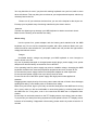
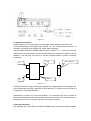
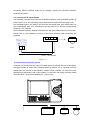
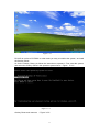
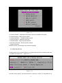
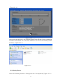
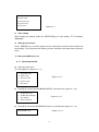
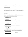
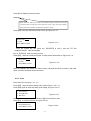
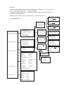
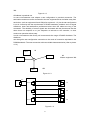
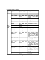
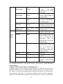
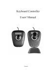
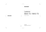
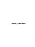
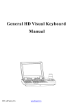
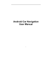
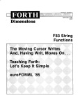
User Manual of PL2125 Notes Some of the instructions mentioned below are based on the Windows(R) Vista operation systems. If you are using any other types of Windows operation systems some of the operations may not be the same. If you do not use windows operation systems, some of the instructions may be different, but it will not affect you use the computer successfully. All instructions mentioned in the manual are all about the general functions of the majority of our products models .A fraction of the described functions may not applicable to your own computer, or that part of your computer functions are not covered in this manual. All model numbers displayed on the illustrations will be PL2125, unless otherwise labeled. There might be some discrepancies between the real objects and the illustration. Please take the real objects as finals. Cautions Our dearest customers, Thank you for purchasing our NKB multi-functional keyboard! Please be sure to read this operation manual before using and take care of it properly. It is a great honor to have you as our customers. In order to help you master the know-how of this multi-functional keyboard as soon as possible, here particularly we write this manual for you. We strive to make this instruction comprehensive and concise so that you can obtain the knowledge of the system configurations, installation procedures, as well as the basic usage of the operation systems which all relative to the NKB multi-functional keyboard .We strongly recommend you to read this manual carefully before using our products. It will help you to make a better use of our product. This manual apply exclusively to the usage and working conditions and environment of the same models of NKB products .It does not indicate the actual configurations and interfaces of the product software and hardware. With respect to the actual configurations, please take the purchased products and the enclosed packing list as finals. This manual may not applicable to other models or configurations of NKB products, so it will not suitable for products of other brand. We have tried our best to avoid the man-made faults so as to ensure that we have provided the most reliable information .But we are unable to give a full satisfaction guarantee for two reasons. First of all, there might be mistakes not detected before printing .Secondly, there might be some omissions occur beyond control during the process of printing, binding and distributing. Please feel free to contact the relevant department of Dowse Electronics Co., Ltd for replacement of a new one when necessary. With the purpose of improving the components or the machine, we may do a little change to the software and hardware of our products from time to time, which may lead to some inconsistency with this manual. But it will not affect you from using our machine substantially. Thank you for your cooperation! Important safety information This chapter helps to use your DS-781NKB multi-functional keyboard safely. Please follow the instruction materials enclosed carefully and keep it safely. User’s notice PL2125 multi-functional keyboard is electronic equipment. The potential safety risk may exist in the power line and the power adapter as well as any other components. Any misuse may lead to physical injury or property loss. In this brochure, the safety risks will be divided into 2 classes. ·Danger Physical injury or death risks are possible. ·Attention In order to protect you from suffering any injuries and assist you to use our NKB keyboard more safely, please make sure to follow the considerations listed below. ·Unpacking Check the outermost skin as well as the power adapter and see whether there exists the breakage or not, particularly these components with the following labels . ·Danger This mark means there is dangerous voltage or dangerous electric current or high energy. Working environments Do not use PL2125 keyboard in the bathroom or any other damp environment. Keep this PL2125 keyboard and its accessories away from liquid. ·Danger Any liquid penetrated may lead to an electric shock. Do not use this keyboard under the environment of thunder and lightning 2 You may block the air vent if you place this working keyboard onto your bed, sofa or some other soft sheets. This may bring the over-heat to your keyboard and its parts, which may ultimately lead to the fire. Please cut off your wireless devices when you are at the hospital or the airport etc. Pls keep your keyboard away from being interfered by the electric waves. ·Attention Thunder and lightning may damage your NKB keyboard or lead to an electric shock. Make sure the working environments are drafty. About using Use the power line, power adapter and the battery pack attached with the NKB keyboard only. Do not use the keyboard together with other products. Make sure your electrical socket outlet suitable for your power cables and can provide the right electric voltage and electric current ·Danger Unsuitable electric voltage may damage your NKB keyboard or even brought an electric shock or the fire. Any use of possibly damaged or old-aged power supply plugs, power supply, lines, power adapter and relevant battery accessories are not allowed. Over operating load for power supply may arise to unstable voltage, damaging the NKB keyboard controller item, data and peripheral equipments and even a cause to fire Do not twist the power supply lines around the power adapter or other objectives. Do not squeeze power supply lines or put heavy items on them Do not mix the use of the same power supply with high-power warts appliances. Attention: Dragging power supply lines by force many cause ware and tear of electric lines damages, splitting and rolling, even hidden perils of incidents from safety. Make sure your hands, legs or your body not touches heat parts of the NKB item for a long time. It may make you feel uncomfortable or cause body pains by touching heat parts of the NKB item for a long time, even in the case that the NKB item is separated from clothes. Do not drop, hit and make scratch on the TFT display screen or put heavy items on them Try to prevent your body from being exposed to liquids spilled from the TFT display screen because of its breaking. If happened unfortunately, please wash it by water at least for 15 minutes 3 Content 1. Summary……………………………………………………………………..…….………….6 1.1. Attention…………………………………………………………..………….….…………. .6 1.2 Function Features……………………………………………………….……….………….6 1.3 Technology Parameter…………………………………………………….………...……...6 2. Connection………………………………………………………………………….….……...6 2.1 Interface instruction…………………………………………………..……………….……..7 2.2 Connect to Matrix…………………………………………………………………………….7 2.3 Connect to PTZ speed dome……………………………………………………………….8 2.4 Connection in security systems…………………..……………………………………….. 8 3. Operate instruction…………………………………………………………………………….9 3.1 Power connection…………………………………………………………………………….9 3.2 Start and stop controller…………………………………………………………………...……9 3.3 Operation system………………………………………………………………………………..9 3.3.1 One key back up…………………………………………………………….……………….12 3.3.2 One key restore…………………………………………………………………...………..13 3.4 TFT screen……………………………………………………………………………………15 3.5 Control the PTZ speed Dome by Navigation key……………………………………………15 3.6 Call the camera ID…………………………………………………………………………..16 3.7 Adjust the PTZ speed dome lens………………………………………………………………16 3.8 PTZ Speed Dome function operation………………………………………………………….16 3.8.1 Preset………………………………………………………………………………………...16 3.8.2 Scan………………………………………………………………………………………….16 3.8.3 Pattern……………………………………………………………………………………….16 3.8.4 Tour…………………………………………………………………………………………17 3.9 Call the main menu……………………………………………………………………………17 3.10 Control the Matrix……………………………………………………………………………17 3.10.1 Call the matrix main menu…………………………………………………………………17 3.10.2 Confirm the setting………………………………………...……………………………….17 3.10.3 Change the monitor ID……………………………………………………………………17 4.0 Control the NKB………………………………………………………………………………17 4.1 Set up the NKB parameter…………………………………………………………………….18 4.1.1 Setup the controller ID……………………………………………..……………………….18 4.1.2 Setup the controller Baud rate……………………………………………………………….19 4.1.3 Display the controller information…………………………………………………………19 4.2 Setup the PTZ speed dome……………………………………………………………………20 4.2.1 Preset……………………………………………………………………………………….20 4.2.2 Scan…………………………………………………………………………………………21 4.2.3 Pattern………………………………………………………………………………………22 4.2.4 Tour…………………………………………………………………………………………22 4.3 Protocol Set up……………………………………………………………………………….22 4.3.1 Pelco Matrix model…………………………………………………………………………22 4.3.2 PTZ speed dome model……………………………………………………………………..22 4 4.4 System setting………………………………………………………………………………...24 4.5 Exit the controller menu……………………………………………………………………..24 5 Controller Menu………………………………………………………………………………...24 6. Using the internet……………………………………………………………………………….25 6.1Wired connection……………………………………………………………………………..25 6.2WIFI connection………………………………………………………………………………25 7 Appendix………………………………………………………………………………………...25 7.1 RS485 bus general knowledge………………………………………………………………..25 7.2 Controller shortcut instruction…………………..……………………………………………28 8 Appendix B……………………………………………………………………………………..29 8.1 System software and hardware compatibility notes…………………………………………..29 8.2 Hard disk instruction…………………………………………………………………………29 5 1. Overview: PL2125 multi-functional keyboard is a combination of general keyboard and built-in computer in Safety monitoring products series. It can control multi-protocol integrated dome cameras, matrix, etc. Equipped with navigation keys, the keyboard can control the camera lens rotating and zooming; Equipped with LCD screen with backlit, the keyboard can display the current operation command, the controlling protocol name, the current dome cameras address, the current monitor address and the state of navigation keys. The equipping of Navigation keys and the LCD screen, make the operator control CCTV system very easy. 1.1 Attention: ●Read the manual, and keep this manual。 ●Pay attention to Matters of Attention in the manual。 1.2 Function Features: ●RS485 control bus, a keyboard in the direct control mode, at most, can connect 31 domes; ●compatible with Multi-Protocol products; ●Can control the camera aperture size, focus distance, magnification; ●Can set and call the ball’s preset point, level scanning and pattern scanning and tour; ●Can control matrix, and through the matrix indirectly control domes; ●Equipped with navigation keys and big LCD screen; ●Video input/output display function; ●Infrared emission function, the data sent content and RS485 of the same; ●Network line test function。 1.3 Technical Parameters ★ electrical specification Input voltage:19V DC Rated Current:1A (19V DC Input) Rated Power:18W Electric current when battery charging:3A ★Communication features Communication Mode:RS485×1, Communication Baud Rate:2400、4800、9600、19200bps ★ Work environment: Operation Temperature:0℃~50℃ Relative Humidity:Less than 90% ★ Physical Characteristics: L*W*H=305mm*210mm*130mm Weight: 1.735KG 2. Connection: Keyboard interfaces are on the back of the keyboard. The keyboard is equipped with multiple interfaces, which includes RS485, VGA output, video input and USB, Easy to connect and control a variety of external devices.(Figure: 2.1) 6 Figure 2.1 2.1 Interface instruction RS485 interface is on the two green terminal seats of the keyboard connection lines. In the keyboard directly controlling mode,RS485(A+,B-)Collects Dome Cameras;In the matrix controlling mode, RS485 can collect other Keyboards. Transfer RS485 interface to RS485-USB converters(picture 2-1.1), then insert it into the USB interface of the Keyboard. So when using NKB built-in computer’s related monitoring software, it will be more convenient to use the keyboard rocker to control monitoring equipment. USB A+ USB connecter RS485 B— Figure 2-1.1 VGA input interface is used for taking the keyboard as a display device. The keyboard can insert equipments with VGA output like PC host and DVR. The maximum input resolution it supports are 1024X768,800X600。 USB interface, used for PC host communication, it is connected to PC host via USB. At this time the keyboard can be used as Mouse equipment. And the Video Input Interface on the keyboard is used for receiving camera’s video signal externally. 2.2 Connect to matrix The keyboard can control PELCO CM6700, CM6800 matrix. Here below taking keyboard 7 connecting PELCO CM6700 matrix as an example, explain the connection between keyboard and matrix. 2. 3 Connect to PTZ speed Domes The keyboard connects Dome cameras via RS485 interfaces. And the RS485 interface of Dome camera is on the connecting plate of Suspension hanger within the upper cover. Pull the Metal button in the hanger, and open the connecting plate, upon which there is a four-control/power plug seat. According to the logo above, can find the corresponding RS485 (A +, B-) interface. Dome cameras made by different manufacturers may have different ways of connection. Please refer to the Installation manual of the Dome cameras when connecting the Keyboard. 12V A+ B- A+B- Dome Power DC 12V-36V Figure 2-3.1 2.4 Connection in security system Controller can directly connect to the PTZ speed dome or indirectly connect to the Matrix, through the matrix to control the PTZ speed dome as (Picture 2-4.1). Controller and PTZ Speed dome will connect to the RS485 in Parallel. Each controller can control the PTZ speed dome independent. And in this situation, it must have one mother controller (Mark controller ID as 1, Baud Rate 9600bps) as(Figure 2-4.2) 8 Matrix Dome1 Dome2 Figure 2-4.1 Controller Attention 1、 One RS485 bus line can connect the 32pcs controller and PTZ speed Dome directly or indirectly, So one controller can control the 31pcs PTZ speed dome directly most. 2、In the system, it can connect the 4pcs controller most, each controller ID will different. Controller1 Controller 3 Controller 4 Controller 2 Dome 1 Dome5 Dome 2 Dome 6 Figure 2-4.2 9 Dome 3 Dome 7 Dome 4 Dome 8 3 . Operate instruction 8” TFT Screen Joystick Keys Figure 3.1 This chapter describes the operation of the NK. Remark, different kind of system has its own special operate. And pls reference to the system’s user manual such as PTZ speed dome and matrix user manual to do some adjusting. 3.1 Power connection Before using the NKB, pls charge the power for the battery. Put in the battery and connect to the adaptor. It will auto charge the power while you connect to the AC adaptor. 1 Connect the power cable to AC adaptor 2 Connect the AC adaptor to NKB 3.2 START/STOP controller Turn the switch to “—”as(Figure 2.1) to START the controller. And turn to“○”to STOP the controller. Attention Do not turn the switch to “○”while you are running controller and not turn to “—”while you are stopping it. NKB will AUTO checking the BAUD RATE, PROTOCOL,TARGET PTZ speed dome and Monitor. Press the MENU, all these information will show on the TFT screen. Attention Pls do not operate the Navigation Key, while the NKB is under initialization the system. 3.3 Operation system NKB support the Windows 2000,Windows XP,Windows Vista Operation system. Screen as(Figure 3-3.1) 10 Figure 3-3.1 PL2125 do not have CD-ROM. In order make you easy to initialize the system, we install the Onekey Ghost. As for the Onekey Ghost, pls follow the instruction to operate it. First, start the system, and select the Onekey Ghost in the operation system list as(Figure 3-3.2) Figure 3-3.2 Onekey Ghost main menu as (Figure 3-3.3) 11 Figure 3-3.3 R. OneKey Restore:Initialization the system, recover to the BACK UP system B. OneKey Backup:BACK UP the system 3. Custom Operation: Definite the item yourself 4. GHO File Search:Search the GHO file 5. GHOST Manual:Manual operate GHOST 6. MS-DOS Command:DOS instruction operate 7. Restart Computer PRESS Chinese, it will change to the Chinese language. 3.3.1 One key back up Pls select the B on the Onekey Ghost list or directly press the B on controller it will enter the BACK UP interface as (Figure 3.3.1-1) Figure 3.3.1-1 And then select the“OK” and start GUOST or select the “Cancel” to stop BCK UP as 12 (Figure 3.3.1-2) Figure 3.3.1-2 After you did the BACK UP, it will create the GHOST fold in E disk. Pls do not delete the document. All the DATA are in this fold, otherwise it can not run the Onekey restore function as(Figure 3.3.1-3) Figure 3.3.1-3 3.3.2 Onekey Restore Select the R.OneKey Restore or directly press the R on keyzone as (Figure 3.3.2-1) 13 And then it will AUTO search the BACK UP document. If has BACK UP before, it will advise you the position about it as(Figure 3.3.2-2) Figure 3.3.2-2 Select the BACK UP and press “ENTER” to the interface for confirm as(Figure 3.3.2-3) Figure 3.3.2-3 And then select the“OK” to enter the GHOST screen or select the Cancel to stop operation as(Figure 3.3.2-4) 14 Figure 3.3.2-4 After restore the system, restart the computer and can enter the new system. 3.4 TFT screen TFT can show the operation information just like:PTZ speed dome ID, Monitor ID, BAUD RATE ect. And at the bottom of the screen, it will show the instruction and navigate operation as ( Figure 3-4.1): TFT screen will have backlight while you operate on it, and 15s (can set by yourself) later, the light will close if you did not do any operate on it. Keyboard V 1.00 Keyboard ID:001 Camera ID:001 Monitor ID:001 Protocol :Pelco-d Baudrate : 2400bps Figure 3-4.1 3.5 Control the PTZ speed Dome by Navigation key Navigation key has two functions, one is manual control the PTZ, the other one is setting the menu. ● While as setting key, UP means select the previous item, DOWN means next item, RIGHT means enter the sub menu or stock the setting and LEFT means exit but not 15 stock. ● Navigation key control the PTZ speed dome can suit the fast or fine movement. 3.6 Call the camera ID 【N】+【CAM】 【N】is the NO key, press the camera ID and press【CAM】key,it will call the target PTZ speed dome. 3.7 Adjust the PTZ speed dome lens ● Zoom: Press【TELE】 ,lens will enlarge the zoom, objects will close. Press【WIDE】 ,lens will reduce the zoom, objects will far.. ● Focus Press【FAR 】, it will focus the far object; Press【NEAR】, it will focus nearobject; Normally, the lens is auto focus. If the image is not clear enough, you can manual adjust the focuse. ● Iris Press【OPEN】 ,manual iris will enlarge, and make more light into the camera. Too much light will make the image too bright and expose. Press【CLOSE】, manual iris will close, and make less light into the camera, and the image will show dark. 3.8 PTZ Speed Dome function operation 3.8.1 Preset Setting the preset: 【SET】+【N】 + 【PRESET】 Call the preset: 【N 】+【PRESET】 【N】means the position ID 3.8.2 Scan Left limit: 【SET】+【1】+【SCAN】 Right limit: 【SET】+【2】+【SCAN】 Start: 【1】+【SCAN】 If need change the scan speed, pls enter the menu to set it. 3.8.3 Pattern ● Set the pattern: 【SET】+【N 】+【PATTERN】+ Pattern path+【SET】+ 0 +【 PATTERN】 Press【SET】key,input the pattern ID,press【PATTERN】key,star the pattern path setup, when finished the setting, press 【SET】key first,then press【0】key and【PATTERN】 16 key to finish the setting. ● Startup pattern: 【N】+【PATTERN】to input the pattern ID,Press【PATTERN】to start pattern Remark: Pls set the running speed and stop time in each PRESET before you run this function( through menu). 3.8.4 Tour Starting TOUR function: 【N】 +【TOUR 】; Input the 【TOUR】 ID, then press the 【TOUR】 key,starting the tour. If just has one TOUR ID, you can direct press the【TOUR】 key to start it. Remark: TOUR path must set in the menu. Before running, pls set the speed between each PRESET. 3.9 Call the Dome main menu 【9】+【5】+【PRESET】 :Input 95,press【PRESET】key, the main menu of aim PTZ speed dome will display on the suitable monitor. About the PTZ speed dome’s function set up, pls refer to the PTZ speed dome’s user manual. 3.10 Control the Matrix 3.10.1 Call the matrix main menu 【SHIFT】+【SET】 : Call the main menu, the menu will display on the object monitor. About the matrix function set up, pls refer to the matrix’s user manual. 3.10.2 Confirm the setting 【ENTER】 :After finishing the matrix setting, press【ENTER】 to confirm and finish it. About the matrix function set up, pls refer to the matrix’s user manual. 3.10.3 Change monitor ID 【N】 +【MON】; Input the monitor ID, then press MON. The image and the menu of the PTZ speed dome will display in the monitor which you just set. 4. Control the NKB ●Controller Setting Turn on the power and press 【MENU】, the system information will display as (Figure 4.1-1), and press again, the information will disappear. You can do all the operation in this situation.. Press【MENU】 and hold 2s, and call the controller’s main menu as(Figure 4.1-1). All the sub menu setting needs enter the main menu. After entering the main menu, press the Figure key or use the joystick to select the menu. 17 1.Keyboard setup 2. Dome setup 3. Protocol select 4. System setup 5. Exit menu Figure 4.1-1 Save setting After finishing the setting, press the 【ENTER】key to save setting; TFT will display “Success”. Back previous menu Press 【PREV】key, or turn the joystick to left, it will back to previous menu and will not save setting. If you want save the setting, pls save it advance and then back to previous menu. 4.1 Set up the NKB parameter 4.1.1 Setup keyboard ID Enter the main menu TFT will display as ( Figure 4.1.1-1) 1. Keyboard setup 2. Dome setup 3. Protocol select 4. System setup 5 .Exit menu Press【1】to select the KEYBOARD SETUP, it will show as ( Figure 4.1.1-2) 1. 2. 3. 4. Figure 4.1.1-1 Set KB ID(1-64):Set Baudrate:2400bps Joy calibrate About keyboard Figure 4.1.1-2 Press【1】and do the KEYBOARD ID set up, it will show as (Figure 4.1.1-3) Figure 4.1.1-3 1.Set KB ID(1-64):- 18 Input the KB ID from 1~64 through the keyboard NO keys. And then press the 【Enter】to save, the screen will display Success as Figure( 4.1.1-5) Success Figure 4.1.1-5 If the ID NO outside the range1~64, it will display Error as Figure(4.1.1-6) Figure 4.1.1-6 Error Press 【PREV】or use the joystick toward to LEFT to back to previous menu. 4.1.2 Set up the controller BAUD RATE Enter the main menu, the TFT will show as Figure (4.1.1-1) . Press【1】, TFT will show as Figure(4.1.1-2) Press【2】select the Baud Rate setting as Figure (4.1.2-1) 2.Set Baud rate: 2400bps(4800bps/9600bps/19200bps) Figure 4.1.2-1 2400bps\4800bps\9600bps\19200bps is available,You can select the Baud rate you need and press the 【 ENTER 】 to save. If your operation is success, the screen will show“Success” Press 【PREV】or use the joystick toward to LEFT to back to previous menu Attention: If connect to the matrix, it must select the 9600bps. And use as computer, it must use 9600bps or 19200bps 4.1.3 Display the Controller Information Enter the menu,TFT will display as 4.1.1-2 ; Press 【4】 ,TFT will display as (figure 4.1.4-1) Version:1.00 KB ID: 001 Protocol: Pelco-d Baudrate:2400bps 19 Figure 4.1.4-1 Press【PREV】 or use the joystick turn LEFT back to previous menu.. The controller menu will display all the controller setting information; include the controller model, controller ID, Protocol and the Baud rate. 4.2 Set up the PTZ speed Dome This chapter describes the operation of the PTZ speed dome. Remark, different kind of system has its own special operate. And pls reference to the system’s user manual as standard. 4.2.1 PRESET Enter the main menu as Figure (4.1.1-1)and press【2】 to enter the dome setting menu as Figure (4.2.1-1);You can move the cursor to select the function you need and set it. Here is the function you can set: Preset, Scan, Pattern, Tour. 1. 2. 3. 4. 5. Set dome preset Set dome scan Set dome pattern Set dome tour Figure 4.2.1-1 Press【1】 enter the dome Preset function setting as Figure (4.2.1-2)。 1. Save preset 2. Show preset 3. Clear preset Figure 4.2.1-2 Item 1 : Save preset;item 2 : Show the preset; Item 3: clear the preset Press【1】 enter the preset, you can input the preset NO as Figure(4.2.1-3)show Preset num: (1-128) Press PREV to back Figure 4.2.1-3 After enter the preset menu you can use navigate key to add or decrease the the preset NO, press the【Enter】 to save as Figure 4.2.1-4 . Or directly use the NO key to input the PRESET NO and then save it . And on the TFT screen will display SUCCESS Success! Figure 4.2.1-4 20 Press【Prev】back to previous menu. Attention: While enter the dome preset menu, the keyboard navigate keyboard can directly control the dome; And the lens control zone (Iris, Focus, zoom) also work available; And in other menu situation, normally the operation is NULL. Press【2】enter the “Show the preset” menu as Figure 4.2.1-5 Preset num: (1-128) Press PREV to back Figure 4.2.1-5 Input the Preset NO and press the 【 ENTER 】 to call it, and the TFT will display“Success" . Use the navigate Key or 【PREV】 back to previous menu. Press【3】 enter the “Clear the Preset” to clear preset information as Figure 4.2.1-6 . Preset num: (1-128) Press PREV to back Figure 4.2.1-6 Input the PRESET NO which you want to clear, and press the Enter to clear it, and it will show “Success" and back to previous men。 4.2.2 Scan Enter the menu as Figure(4.1.1-1) Press【2】 enter the dome setting menu as the Figure(4.2.1-1); Press【2】again to enter the dome scan setting as Figure 4.2.2-1 1. Set left limit 2. Set right limit 3. Run scan Figure 4.2.2-1 Dome scan setting include the: Left limit, Right Limit and Run scan Press【1】 to set the Left limit as Figure 4.2.2-2. Press ENTER sure Press PREV to back Figure 4.2.2-2 21 While enter the dome limit setting menu, move the dome to the suitable position, and press【Enter】to save and will show “Success" and back to previous menu. Select the item 2 to set the Right limit, and do the same as the left limit setting, Back to the menu and press【3】to operate the Run Scan Attention: While enter the dome SCAN menu, the keyboard navigate keyboard can directly control the dome; And the lens control zone (Iris, Focus, zoom) also work available; And in other menu situation, normally the operation is NULL. 4.2.3 Pattern Enter the menu as the Figure (4.1.1-1) Press【2】 enter the dome setting menu as the Figure (4.2.1-1); And then press【3】 enter the pattern setting as Figure 4.2.3-1 1. Pattern num: 2. Set pattern 3. Run pattern Figure 4.2.3-1 After enter the menu, the system need input the pattern information you want, you can put in the Pattern ID (ID range base on the PTZ speed dome you use) and press the 【ENTER】to confirm. The cursor will skip to the next item to set the PATTERN information. If you already have it, you can skip it and select the 【3】 to run the pattern directly. Pattern setting:After enter the pattern setting menu, move the dome do the suitable position and press the 【1】 to start record the pattern information. The screen will display“Start ……,as the Figure 4.2.3-2. Press“0 ” to finish the pattern record, and the screen will show“Success” and back to the previous menu. Press 1 to start Press 0 to start Press PREV to back Figure 4.2.3-2 Attention: While enter the dome PATTERN menu, the keyboard navigate keyboard can directly control the dome; And the lens control zone (Iris, Focus, zoom) also work available; And in other menu situation, normally the operation is NULL. Remark: While you want to run the PATTERN, you must set the STOP TIME and Speed in each PRESET. Otherwise this function will not working. 4.2.4 Tour set up Press【2】 enter the dome setting menu, as the Figure 4.2.1-1 show, And then press【4】enter the tour setting as the Figure 4.2.4-1 show. 1. Tour num: 2. Insert preset 3. Run tour Figure 4.2.4-1 22 After enter the menu, you need input the TOUR information, the range you can put is 1~6, and press the 【ENTER】. The mouse will auto skip to the second TOUR setting. If you have already set it, you can skip it. And it will show the“Success” and back to the previous menu. Select the Item 2 as picture(4.2.4-2), you need input the tour preset, and in the second item you need put in the speed information, the range is (1-127); In the third item you need input the time how long it need to stop, the range is (1-255). After finishing all the step, press the 【ENTER】 and will display “Success”and back to previous menu. 1. Preset num: 2. Speed : 3. DWell : Figure 4.2.4-2 Press【3】Run the TOUR Warning: Insert the tour can not work now 4.3 Protocol set up Enter the menu as Figure(4.1.1-1) , Press【3】 enter the Protocol setting as Figure (4.3-1) 1. Matrix 2. Dome Figure 4.3-1 4.3.1 Pelco Matrix model Press【1】 enter the PELCO Matrix model as the Figure (4.3.1-1); And then press the【ENTER】 to select the Protocol and back to previous menu. Figure 4.3.1-1 1.Pelco Matrix 4.3.2 Dome control model Press 【2】enter the dome control model as the Figure ( 4.3.2-1). According to the user’s need, select the suitable PROTOCOL and back to the previous menu. 1.Factory 2.Pelco-p 3.Pelco-d 4.4 System Setting 1.System mode: 2.Buzzer: 3.key time/s: 4.LCD Backlight: 5.USB Mode: 6.Brightness: 7.Contrast: 8.Saturation: 9. Language 10.Init System: Press PREV to back Figure 4.3.2-1 (can select the key4) as Figure 4.4 PAL/NTSC ON/OFF 000~255 000~100 Mouse/PCKEY/NONE 000~255 000~255 000~255 CHN/ENG 23 ON/OFF Note : USB Mode if choice NONE, joystick will show was locked, can't support the mouse function. Figure 4.4 Instruction: 1.System choice 2.Buzzer function choose 3.Screen save setting(Unit:second,set as 0 means cancel the screen save) 4. Back light adjust 5. USB model mode 6.Brightness 7. Contrast 8.Color 9.lanague 10.system initialization 4.5 Exit the controller menu Enter the menu as picture (4.2.1-1) and press the 【5】to exit the menu. Preset num: 5、Controller menu (1-128) Press PREV to back 1. Save preset Preset num: (1-128) 2. Show preset Press PREV to back 3. Clear preset Preset num: (1-128) Press PREV to back 1. Keyboard setup 1. Set KB ID(1-64):- 1. Set left limit 2. Set Baudrate:2400bps 2. Set right limit 3. Joy calibrate 3. Run scan 4. About keyboard 2. Dome setup Set dome preset 2. Set dome scan 3. Set dome pattern 4. Set dome tour 3. Run pattern Press 1 to start Press 0 to start Press PREV to 1. Tour num: back 2. Insert preset Matrix 2. Dome 1. Preset num: 3. Run tour 3. Protocol setup 1.System mode: PAL/NTSC 4. System setup 2.Buzzer: ON/OFF 3.key time/s: 000~255 1. Factory 5.USB Mode: Mouse/Pckey/none 2. Pelco-p 6.Brightness: 000~255 3. Pelco-d 7.Contrast: 000~255 8.Saturation: 000~255 9. Language CHN/ENG 10.Init System: ON/OFF Press PREV to back V1.00 Keyboard ID:001 5. Exit menu 1. Pelco Matrix 4.LCD Backlight: 000~100 keyboard Camera ID:001 Monitor ID:001 Protocol :Pelco-d Baud rate :2400bps Press PREV to back 2. Set pattern 5. 1. Press PREV to back Press ENTER sure 1. Pattern num: 1. Press ENTER sure 24 2. Speed : 3. Well : 6 Using the Internet As a global network, Internet connected worldwide computers, providing services such as e-mail, information retrieval, electronic Business, web browsing and entertainment function. You can access the computer through the Internet the following ways: Wired: wired connection. Wireless network technology: wireless technology connection. 6.1 Wired connection Wired connection is a safe and reliable method to connect computer. Generally, these two access methods are widely used. Cable Cable Internet service using cable connected to residential cable TV network to achieve network communication DSL DSL is a series of related technologies that through the regular telephone line home and small business to provide high-speed network access. 6.2 WIFI Connection Wireless connectivity provides mobile Internet access, so you can keep online in the wireless signal coverage area . This method can establish a wireless connection to the Internet. Wi-Fi Wi-Fi wireless LAN can cover such as home, office, several buildings and other small areas. You need an access point (such as a wireless router) to achieve the connection. Wi MAX Wi MAX network connect multiple wireless LAN system to cover the urban area, that can provide high-speed broad and access 25 Comply with the different model configured the suitable wireless USB adapter. (Each model has its own USB adapter and the corresponding drive manual) 7. Appendix 7.1 RS485 Bus General Knowledge ●RS485 Bus General Character According to RS485 industrial standards, RS485 Bus is of half-duplexes data transmission cables with characteristic impedance as 120. The maximum load capacity is 32 unit loads (including main controller and controller equipment) Distance of RS485 bus transmission While use the 0.56mm (24AWG) twisted cable as the communication, the farthest distance it can reach as follow based on the different Baud rate: Baud rate Max.distance 2400bps 1800M 4800bps 1200M 9600bps 800M 19200bps 600M If user selects thinner cables, or installs the dome in an environment with strong electromagnetic interference, or connects lots of equipment to the RS485 Bus, the maximum transmitting distance will be decreased. To increase the maximum transmitting distance, do the contrary.。 ●Connection and termination resistance The RS485 standards require a daisy-chain connection between the equipment. There must be termination resistance with 120 impedance at both ends of the connection (refer to picture 4-1.1).Please refer to picture 4-1.2 for simple connection But “D” should not exceed 7m。 ……….. 120Ω 1# 2# 3# 4# 32# Figure 4-1.1 A+ ………… D BA+ 120Ω 1# B- ………… 120Ω 2# 3# 26 4# 32# Figure 4-1.2 ●Problems in practical use In some circumstances user adopts a star configuration in practical connection. The termination resistors must be connected to the two equipments that are father away from each other, such as equipment1# and 15# (refer to picture 4-1.3). As the star configuration is not in conformity with the requirements of RS485 standards, problems such as signal reflections, lower anti-interference performance arise when the cables are long in the connection. The reliability of control signals are decreased with the phenomena that the dome dose not responds to or just responds at intervals to the controller, or dose continuous operation without stop. In such circumstances the factory will recommends the usage of Rs485 distributor. The distributor can change the star configuration connection to the mode of connection stipulated in the RS485standards. The new connection achieves reliable data transmission (refer to picture 4-1.4) 120Ω 1# 6# Master equipment 32# 120Ω 15# Figure 4-1.3 A+ 120Ω 1# 120Ω 2# B- . . . 120Ω 3# Figure 4-1.4 27 7.2 Controller short cut operation WORK Mode Direct Control Mode Short cut Operation Object Function 【POWER】 Controller ON/OFF Power 【MENU】 Controller System information Retrieve 【N】+【CAM】 High Speed camera dome Input camera ID , Press 【CAM】,to call the object camera . 【TELE】 High Speed camera dome Press【TELE】 ,increase the multiple of lens 【WIDE】 High Speed camera dome Press【WIDE】 ,reduce the multiple of lens. 【FAR】 High Speed camera dome Press【FAR】 ,far focus . 【NEAR】 High Speed camera dome Press【NEAR】 ,near focus. 【CLOSE】 High Speed camera dome Press【CLOSE】 ,reduce iris. 【OPEN】 High Speed camera dome Press【OPEN】 ,increase iris. 【 SET 】 + 【 N 】 + 【PRESET】 High Speed camera dome Adjust the image to object position ,press【SET】 ,input press 【 N 】 ,then press 【 PRESET 】 ,to set press point. 【N】+ 【PRESET】 High Speed camera dome Input press point 【N】 ,press 【 PRESET 】, to call the preset point . 【 SET 】 + 【 1 】 + 【SCAN】 High Speed camera dome Adjust the image to object position,press【SET】 , input 【 1 】, then press 【SCAN】then press scan left limit . 【 SET 】 + 【 2 】 + 【SCAN】 High Speed camera dome Adjust the image to object position,press【SET】 input 【 2 】 , then press 【SCAN】then press scan light limit 。 【1】+【SCAN】 High Speed camera dome Input【1】 ,press【SCAN】 , to run scan. 28 PELCO Matrix Mode 【 SET 】 + 【 N 】 + 【PATTERN】 High Speed camera dome Press【SET】,input PAT 【 N 】 , then press 【 PATTERN 】, to record pattem path . 【 SET 】 + 【 0 】 + 【PATTERN】 High Speed camera dome Press【SET】 ,input in 【0】 , then press【PATTERN】 ,to save patter path . 【N】+【PATTERN】 High Speed camera dome Input in the pattem path 【1-4】,press 【PATTERN】, to start pattem path. 【N】+ 【TOUR】/ 【TOUR】 High Speed camera dome Input the TOUR NO, press 【TOUR】 or directly press 【TOUR】to start the Tour. 【9】+【5】+ 【PRESET】 High Speed camera dome Input 95 and press【Preset】 to call the menu 【SHIFT】+ 【SET】 Matrix Press【SHIFT】and 【SET】 to call the matrix menu 【PREV】 Matrix Press 【PREV】skip to the previous dome, hold on 2sec on 【 PREV 】 to continuously skip the sixteen domes of connection matrix forwards 【NEXT】 Matrix Press 【NEXT】skip to the previous dome, hold on 2sec on 【 NEXT 】 to continuously skip the sixteen domes of connection matrix back wards 【Stop】 Matrix Stop switch 【ENTER】 Matrix After program, press【Enter】 to confirm. 【N】+ 【MON】 Matrix Input monitor ID, press 【 Cam 】 to select object monitor Note: 【PRE】=【PRESET】 【PAT】=【PATTERN】 【SHI=SHIFT】 【ENT=【ENTER】 8 Appendixes B 8.1 System software and hardware compatibility notes Operating system (such as Windows 2000, Windows XP, Windows Vista, etc.) and application software (such as word processing, database software, etc.) should have its own manual. If you encounter problems when using these procedures, you should check their respective instructions. The machine's operating system and any application software can be separated from function of the machine itself , it also can't interpret the 29 functions of any pre-installed software as the machine itself. If the hardware or software was provided by third-party, DOWSE don't provide any effective commitment and service. 8.2 Hard disk instruction Dear user, you may find there are some differences of hard drive capacity between the process of using the computer's and operating system ,for example: the computer's 80GB hard disk is displayed in the operating system was less than 80GB, the reason neither installed incorrectly nor other problem , this is normal situation in the computer field. This phenomenon is mainly due to the following reasons: the different calculated capacity standards between hard drive manufacturers and computer operating system. Hard disk manufacturers used in hard disk capacity is 1000 binary, that is: 1G = 1,000 MB, 1MB = 1,000 KB, 1KB = 1,000 byte; However, the operating system used in identifying is 1024 binary, that is: 1GB = 1,024 MB, 1MB = 1,024 KB, 1KB = 1,024 byte. because they are different calculated standards, leading to their difference in the operating system .For example, the nominal drive is XG, even in any unused , the capacity of the operating system only: X × 1000 × 1000 × 1000 / (1024 × 1024 × 1024) ≈ X × 0.931 G, If used , the space will be less than X × 0.931 G. In addition, the hard disk is partitioned and formatted, to save system files ,the system will take up some space on your hard drive. For these reasons, you can understand available hard disk space in the operating system should less than the computer. 30